Embed Size (px)
Citation preview
1 Harpst Street • Arcata, California 95521-8299 • 707 826-3646 • fax 707 826-5888 • humboldt.edu
PLANNING DESIGN CONSTRUCTION SUSTAINABILITY OPERATIONS MANAGEMENT
DDC CONTROL SYSTEM – SEQUENCE OF
OPERATIONS
RFP #PW17-2 Exhibit I
Humboldt State University DDC Control System – Sequence of Operations
2
Index HARRY GRIFFITH HALL ................................................................................................................................... 3
NATURAL RESOURCES ................................................................................................................................... 9
SIEMENS HALL ............................................................................................................................................. 15
STUDENT HEALTH CENTER .......................................................................................................................... 20
SCIENCE D&E ............................................................................................................................................... 31
RFP #PW17-2 Exhibit I
Humboldt State University DDC Control System – Sequence of Operations
3
HARRY GRIFFITH HALL
1. AIR HANDLING UNIT AHU‐1 (MIXED AIR DUAL DUCT)
Occupied Mode: The unit shall run whenever it is scheduled for operation by the buildings adjustable weekly operation schedule, or when requested by a minimum 10% (adj.) weighted average demand from the zone boxes due to optimal start or night setback operation. AHU Optimal Start: The unit shall start prior to scheduled occupancy based on the time necessary for the zones to reach their occupied setpoints. The start time shall automatically adjust based on changes in outside air temperature and zone temperatures. The optimal start logic will have a maximum unoccupied startup time of 2 hrs (adj.). Supply Air Smoke Detection: The unit shall shut down and generate an alarm upon receiving a supply air smoke detector status. Supply Fan: The supply fan shall run whenever the unit is enabled. Alarms shall be provided as follows:
Supply Fan Failure: Commanded on, but the status is off.
Supply Fan in Hand: Commanded off, but the status is on.
Supply Fan Runtime Exceeded: Status runtime exceeds a user definable limit (adj.). Return Fan: The Return fan shall run whenever the unit is enabled. Alarms shall be provided as follows:
Return Fan Failure: Commanded on, but the status is off.
Return Fan in Hand: Commanded off, but the status is on.
Return Fan Runtime Exceeded: Status runtime exceeds a user definable limit (adj.). High Static Shutdown: The unit shall shut down and generate an alarm upon receiving an high static shutdown signal. Static Pressure Balancing Dampers – Both Hot and Cold Ducts: Static pressure is measured in each of the (6) main branch ducts. In occupied mode, the damper actuator at each of the branch ducts shall modulate to maintain a constant downstream duct static pressure of 0.75“w.c. (adj.). When the unit is in unoccupied mode, the hot duct balancing damper will open completely. Building static pressure will be measured centrally in the corridor of each floor for monitoring purposes. Hot Deck ‐ Heating Supply Air Temperature Setpoint Reset On Outside Air: For future use; the heating valve is not currently used for this unit. The heating supply air temperature setpoint shall reset based on outside air temperature. As
RFP #PW17-2 Exhibit I
Humboldt State University DDC Control System – Sequence of Operations
4
outside air temperature drops from 55°F (adj.) to 40°F (adj.) the heating supply air temperature setpoint shall reset upwards from 85°F (adj.) to 110°F (adj.). Hot Deck ‐ Heating Coil Valve: For future use; the heating valve is not currently used for this unit. The controller shall measure the heating supply air temperature and modulate the heating coil valve to maintain the hot deck setpoint. Alarms shall be provided as follows:
High Heating Supply Air Temp: If the heating supply air temperature is greater than 120°F (adj.).
Low Heating Supply Air Temp: If the heating supply air temperature is 5°F (adj.) less than setpoint.
Cold Deck ‐ Cooling Supply Air Temperature Setpoint – Outside Air Reset: Initial cold deck setpoint shall be 55°F (adj.) The cooling supply air temperature setpoint shall reset based on outside air temperature. As outside air temperature drops from 55°F (adj.) to 30°F (adj.) the cooling supply air temperature setpoint shall reset upwards from 55°F (adj.) to 60°F (adj.). Cold Deck Supply Air Temperature: The controller shall monitor the mixed air temperature and alarms shall be provided as follows:
High Mixed Air Temp: If the cold deck supply air temperature is greater than 90 °F (adj.).
Low Mixed Air Temp: If the cold deck supply air temperature is less than 45°F (adj.). Economizer (modulating outside air, exhaust air, and return air dampers): The controller shall measure the mixed air temperature and modulate the economizer dampers in sequence to maintain the mixed air temperature at the cold deck temperature setpoint. The economizer shall be enabled whenever:
Outside air temperature is less than 65°F (adj.).
AND the outside air temperature is less than the return air temperature.
AND the supply fan status is on. The economizer shall close whenever:
The economizer is not enabled by the parameters above.
Mixed air temperature drops below 45°F (adj.).
OR on loss of supply fan status.
OR the freeze stat (if present) is on. Minimum Outside Air Ventilation ‐ Carbon Dioxide (CO2) Control: When in the occupied mode, the controller shall measure the return air CO2 concentration and modulate the outside air dampers open on rising CO2 concentrations, overriding normal damper operation to maintain a CO2 setpoint of 850 ppm (adj.). The outside air and exhaust air dampers shall close and the return air damper shall open when the unit is off.
RFP #PW17-2 Exhibit I
Humboldt State University DDC Control System – Sequence of Operations
5
Return Air Temperature: The controller shall monitor the return air temperature. Alarms shall be provided as follows:
High Return Air Temp: If the return air temperature is greater than 90°F (adj.).
Low Return Air Temp: If the return air temperature is less than 45°F (adj.).
2. EXHAUST FANS EF‐2 THRU EF‐5
The exhaust fans shall be enabled whenever the unit is enabled. Exhaust fans will stop during unoccupied modes. Alarms shall be provided as follows:
Exhaust Fan Failure: Commanded on, but the status is off.
Exhaust Fan in Hand: Commanded off, but the status is on.
Exhaust Fan Runtime Exceeded: Status runtime exceeds a user definable limit (adj.).
3. HEATING HOT WATER SYSTEM
The heating hot water system shall be enabled whenever:
Outside air temperature is less than 70°F (adj.).
AND the heating hot water system is scheduled for operation.
AND there is a weighted average heating demand from at least 10% (adj.) of the zone mixing boxes.
Heating Hot Water System ‐ Run Conditions:
Once enabled, the heating hot water controller will start the lead loop pump. The boiler shall be
enabled 2 minutes (adj.) after pump status is proven on and shall run subject to its own internal
safeties and controls. Upon shutdown, the lead loop pump will continue to run for a period of 15
minutes (adj.) after the boiler has been commanded off.
Boiler Reset:
The controller will send a reset signal to adjust the boilers hot water set point based on outside air
temperature. As the outside air temperature rises from 55 ° F (adj.) to 65 ° F (adj.) the boiler’s hot
water setpoint will be adjusted from 180 ° F (adj.) to 160 ° F (adj.).
Alarms shall be provided as follows:
Boiler Failure: Commanded on, but the status is off. (Boiler run state may be determined
based on the HWS temperature.)
Boiler Running in Hand: Commanded off, but the status is on.
Boiler Runtime Exceeded: Status runtime exceeds a user definable limit.
RFP #PW17-2 Exhibit I
Humboldt State University DDC Control System – Sequence of Operations
6
Hot Water Pump Lead/Lag Operation:
The two hot water pumps shall operate in a lead/lag fashion.
The lead pump shall run first.
On failure of the lead pump, the lag pump shall run and the lead pump shall turn off.
The designated lead pump shall rotate upon one of the following conditions (user selectable):
manually through a software switch
if pump runtime (adj.) is exceeded
daily
weekly
monthly
Alarms shall be provided as follows:
Hot Water Pump X
Failure: Commanded on, but the status is off.
Running in Hand: Commanded off, but the status is on.
Runtime Exceeded: Status runtime exceeds a user definable limit.
Hot Water Temperature Monitoring:
The following temperatures shall be monitored:
Hot water supply.
Hot water return.
Alarms shall be provided as follows:
High Hot Water Supply Temp: If greater than 200°F (adj.).
Low Hot Water Supply Temp: If less than 100°F (adj.).
5. DUAL DUCT ZONE MIXING BOXES
Run Conditions ‐ Scheduled:
The unit shall run according to a user definable time schedule in the following modes:
Occupied Mode: The unit shall maintain
A 75°F (adj.) cooling setpoint
A 68°F (adj.) heating setpoint.
Unoccupied Mode (night setback): The unit shall maintain
A 85°F (adj.) cooling setpoint.
A 55°F (adj.) heating setpoint.
Alarms shall be provided as follows:
RFP #PW17-2 Exhibit I
Humboldt State University DDC Control System – Sequence of Operations
7
High Zone Temp: If the zone temperature is greater than the cooling setpoint by a user
definable amount (adj.).
Low Zone Temp: If the zone temperature is less than the heating setpoint by a user
definable amount (adj.).
Zone Setpoint Adjust:
The occupant shall be able to adjust the zone temperature heating and cooling setpoints at the
zone sensor.
Zone Optimal Start:
The unit shall use an optimal start algorithm for morning start‐up. This algorithm shall minimize the
unoccupied warm‐up or cool‐down period while still achieving comfort conditions by the start of
scheduled occupied period.
Temperature Control:
The unit shall maintain zone setpoints by controlling the airflow through each of the following:
Occupied:
When zone temperature is greater than its cooling setpoint, the mixing box shall modulate
the damper toward the maximum cooling airflow position until the zone is satisfied.
When zone temperature is less than its heating setpoint, the mixing box shall modulate the
damper toward the maximum heating airflow position until the zone is satisfied. A heating
signal of 5% or more (adj.) will constitute a heating demand from the zone.
Unoccupied:
Damper will default to the heating position.
Environmental Index:
When the zone is occupied, the controller will monitor the deviation of the zone temperature from
the heating or cooling setpoint and calculate a 0 ‐ 100% Environmental Index which gives an
indication of how well the zone is maintaining comfort. The controller will also calculate the
percentage of time since occupancy began that the Environmental Index is 70% or higher.
Optionally, a weighting factor can be configured to adjust the contribution of the zone to the rollup
average index based upon the floor area of the zone, importance of the zone, or other static
criteria.
6. COMPUTER ROOM 115, AC‐1
Run Conditions – Room Demand: AC‐1 shall be enabled whenever room temperature rises above a 76°F (adj.) cooling setpoint. Whenever AC‐1 is enabled, the dual duct zone mixing box serving this space will be overridden to the full cooling position.
RFP #PW17-2 Exhibit I
Humboldt State University DDC Control System – Sequence of Operations
8
Alarms shall be provided:
If zone temperature rises above 85 °F (adj.).
RFP #PW17-2 Exhibit I
Humboldt State University DDC Control System – Sequence of Operations
9
NATURAL RESOURCES
1. AIR HANDLING UNIT AH‐1 (MIXED AIR SINGLE DUCT)
Occupied Mode: The unit shall run whenever it is scheduled for operation by the buildings adjustable weekly operation schedule, or when requested by a minimum 10% (adj.) weighted average demand from the zone boxes due to optimal start or night setback operation.
AHU Optimal Start:
The unit shall start prior to scheduled occupancy based on the time necessary for the zones to
reach their occupied setpoints. The start time shall automatically adjust based on changes in
outside air temperature and zone temperatures. The optimal start logic will have a maximum
unoccupied startup time of 2 hrs (adj.).
Supply Fan: Supply fan shall run at its pre‐determined speed (adj.) whenever the unit is enabled. Alarms shall be provided as follows:
Supply Fan Failure: Commanded on, but the status is off.
Supply Fan in Hand: Commanded off, but the status is on.
Supply Fan VFD Fault.
Supply Fan Runtime Exceeded: Status runtime exceeds a user definable limit (adj.). Supply Air Smoke Detection: The unit shall shut down and generate an alarm upon receiving a supply air smoke detector status. Cold Deck ‐ Cooling Supply Air Temperature Setpoint – Outside Air Reset: Initial cold deck setpoint shall be 55°F (adj.) The cooling supply air temperature setpoint shall reset based on outside air temperature. As outside air temperature drops from 55°F (adj.) to 30°F (adj.) the cooling supply air temperature setpoint shall reset upwards from 55°F (adj.) to 60°F (adj.). Cold Deck Supply Air Temperature: The controller shall monitor the mixed air temperature and alarms shall be provided as follows:
High Mixed Air Temp: If the cold deck supply air temperature is greater than 90 °F (adj.).
Low Mixed Air Temp: If the cold deck supply air temperature is less than 45°F (adj.). Outside Air Damper: The outside air damper shall open to its pre‐determined minimum outside air position any time that the unit is occupied. Economizer (modulating outside air damper): The controller shall measure the mixed air temperature and modulate the outside air damper to maintain the mixed air temperature at the cold deck temperature setpoint.
RFP #PW17-2 Exhibit I
Humboldt State University DDC Control System – Sequence of Operations
10
The economizer shall be enabled whenever:
Outside air temperature is less than 65°F (adj.).
AND the outside air temperature is less than the return air temperature.
AND the supply fan status is on. The economizer shall close whenever:
The economizer is not enabled by the parameters above.
Mixed air temperature drops below 45°F (adj.).
OR on loss of supply fan status.
OR the freeze stat (if present) is on. Minimum Outside Air Ventilation ‐ Carbon Dioxide (CO2) Control: When in the occupied mode, the controller shall measure the return air CO2 concentration and modulate the outside air damper open on rising CO2 concentrations, overriding normal damper operation to maintain a CO2 setpoint of 850 ppm (adj.). The outside air damper shall close when the unit is off. Return Air Temperature: The controller shall monitor the return air temperature. Alarms shall be provided as follows:
High Return Air Temp: If the return air temperature is greater than 90°F (adj.).
Low Return Air Temp: If the return air temperature is less than 45°F (adj.).
2. AIR HANDLING UNIT AH‐2 (MIXED AIR SINGLE DUCT)
Occupied Mode: The unit shall run whenever it is scheduled for operation by the buildings adjustable weekly operation schedule, or when requested by a minimum 10% (adj.) weighted average demand from the zone boxes due to optimal start or night setback operation.
AHU Optimal Start:
The unit shall start prior to scheduled occupancy based on the time necessary for the zones to
reach their occupied setpoints. The start time shall automatically adjust based on changes in
outside air temperature and zone temperatures. The optimal start logic will have a maximum
unoccupied startup time of 2 hrs (adj.).
Supply Fan: Supply fan shall run whenever the unit is enabled. Alarms shall be provided as follows:
Supply Fan Failure: Commanded on, but the status is off.
Supply Fan in Hand: Commanded off, but the status is on.
Supply Fan Runtime Exceeded: Status runtime exceeds a user definable limit (adj.).
RFP #PW17-2 Exhibit I
Humboldt State University DDC Control System – Sequence of Operations
11
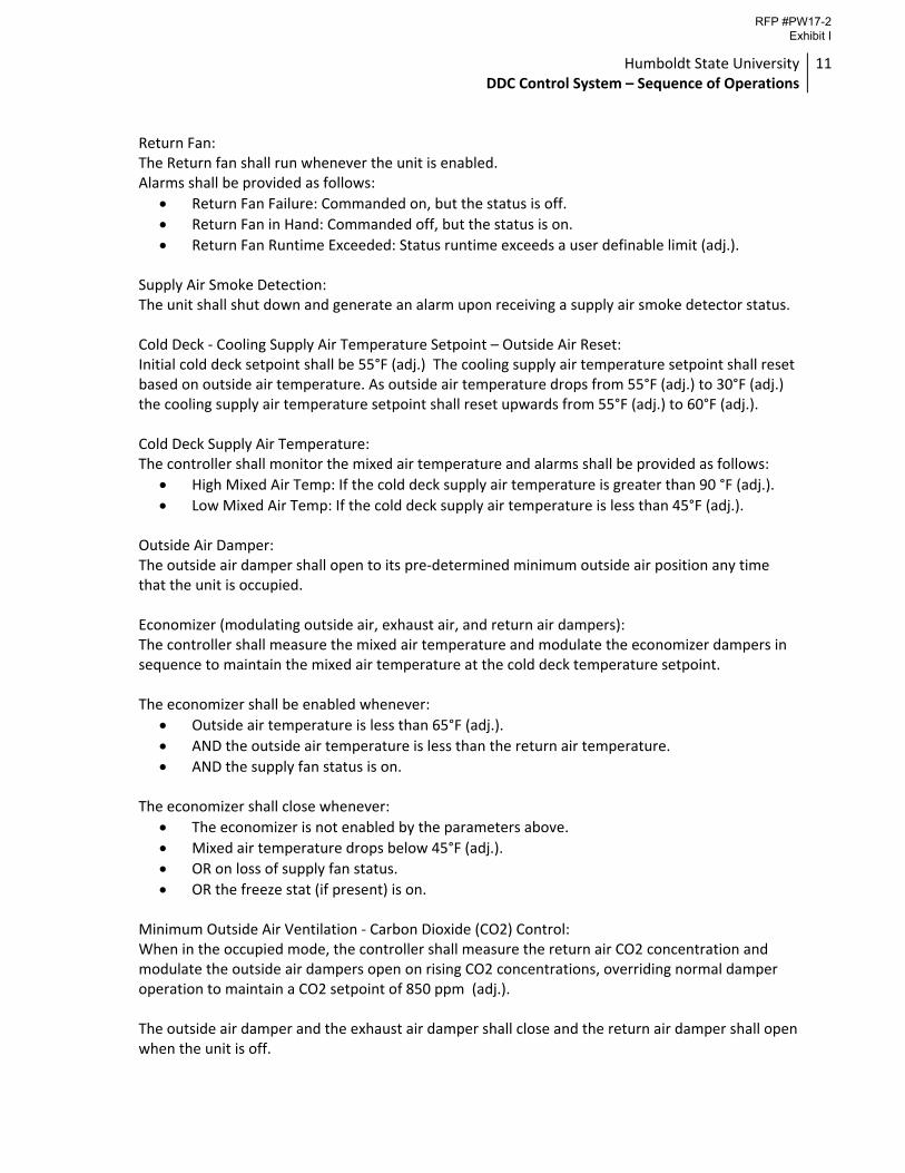
Return Fan: The Return fan shall run whenever the unit is enabled. Alarms shall be provided as follows:
Return Fan Failure: Commanded on, but the status is off.
Return Fan in Hand: Commanded off, but the status is on.
Return Fan Runtime Exceeded: Status runtime exceeds a user definable limit (adj.). Supply Air Smoke Detection: The unit shall shut down and generate an alarm upon receiving a supply air smoke detector status. Cold Deck ‐ Cooling Supply Air Temperature Setpoint – Outside Air Reset: Initial cold deck setpoint shall be 55°F (adj.) The cooling supply air temperature setpoint shall reset based on outside air temperature. As outside air temperature drops from 55°F (adj.) to 30°F (adj.) the cooling supply air temperature setpoint shall reset upwards from 55°F (adj.) to 60°F (adj.). Cold Deck Supply Air Temperature: The controller shall monitor the mixed air temperature and alarms shall be provided as follows:
High Mixed Air Temp: If the cold deck supply air temperature is greater than 90 °F (adj.).
Low Mixed Air Temp: If the cold deck supply air temperature is less than 45°F (adj.). Outside Air Damper: The outside air damper shall open to its pre‐determined minimum outside air position any time that the unit is occupied. Economizer (modulating outside air, exhaust air, and return air dampers): The controller shall measure the mixed air temperature and modulate the economizer dampers in sequence to maintain the mixed air temperature at the cold deck temperature setpoint. The economizer shall be enabled whenever:
Outside air temperature is less than 65°F (adj.).
AND the outside air temperature is less than the return air temperature.
AND the supply fan status is on. The economizer shall close whenever:
The economizer is not enabled by the parameters above.
Mixed air temperature drops below 45°F (adj.).
OR on loss of supply fan status.
OR the freeze stat (if present) is on. Minimum Outside Air Ventilation ‐ Carbon Dioxide (CO2) Control: When in the occupied mode, the controller shall measure the return air CO2 concentration and modulate the outside air dampers open on rising CO2 concentrations, overriding normal damper operation to maintain a CO2 setpoint of 850 ppm (adj.). The outside air damper and the exhaust air damper shall close and the return air damper shall open when the unit is off.
RFP #PW17-2 Exhibit I
Humboldt State University DDC Control System – Sequence of Operations
12
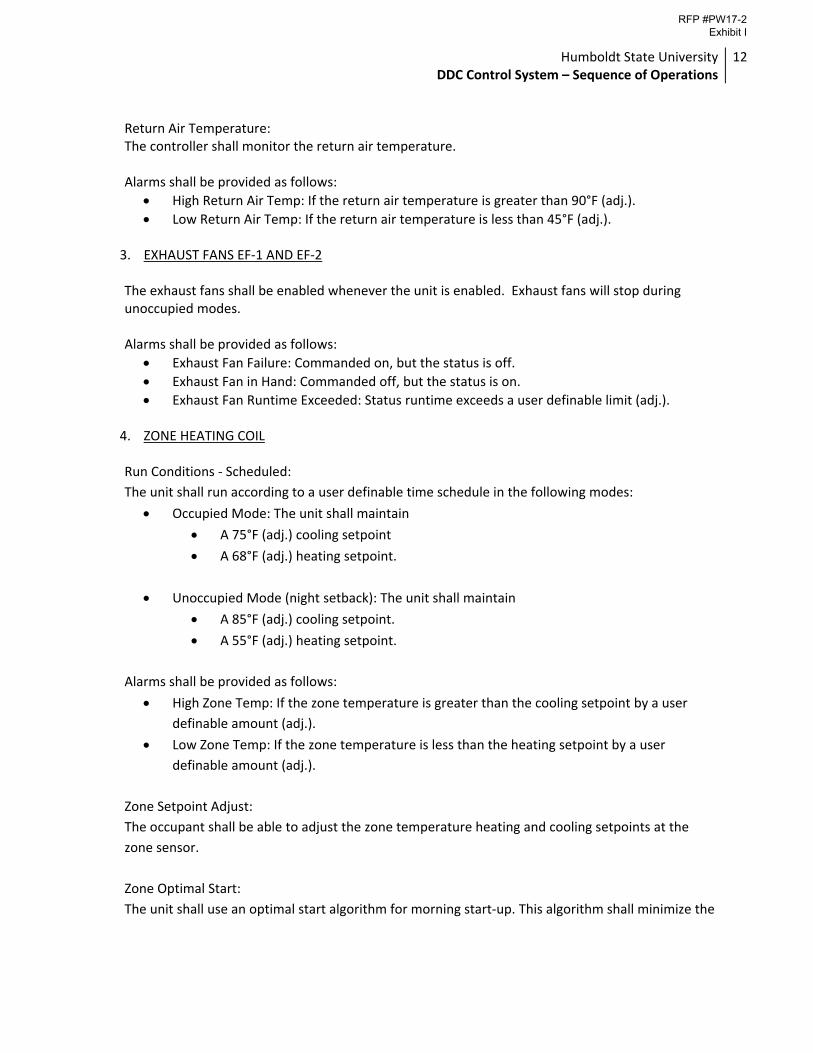
Return Air Temperature: The controller shall monitor the return air temperature. Alarms shall be provided as follows:
High Return Air Temp: If the return air temperature is greater than 90°F (adj.).
Low Return Air Temp: If the return air temperature is less than 45°F (adj.).
3. EXHAUST FANS EF‐1 AND EF‐2
The exhaust fans shall be enabled whenever the unit is enabled. Exhaust fans will stop during unoccupied modes. Alarms shall be provided as follows:
Exhaust Fan Failure: Commanded on, but the status is off.
Exhaust Fan in Hand: Commanded off, but the status is on.
Exhaust Fan Runtime Exceeded: Status runtime exceeds a user definable limit (adj.).
4. ZONE HEATING COIL
Run Conditions ‐ Scheduled:
The unit shall run according to a user definable time schedule in the following modes:
Occupied Mode: The unit shall maintain
A 75°F (adj.) cooling setpoint
A 68°F (adj.) heating setpoint.
Unoccupied Mode (night setback): The unit shall maintain
A 85°F (adj.) cooling setpoint.
A 55°F (adj.) heating setpoint.
Alarms shall be provided as follows:
High Zone Temp: If the zone temperature is greater than the cooling setpoint by a user
definable amount (adj.).
Low Zone Temp: If the zone temperature is less than the heating setpoint by a user
definable amount (adj.).
Zone Setpoint Adjust:
The occupant shall be able to adjust the zone temperature heating and cooling setpoints at the
zone sensor.
Zone Optimal Start:
The unit shall use an optimal start algorithm for morning start‐up. This algorithm shall minimize the
RFP #PW17-2 Exhibit I
Humboldt State University DDC Control System – Sequence of Operations
13
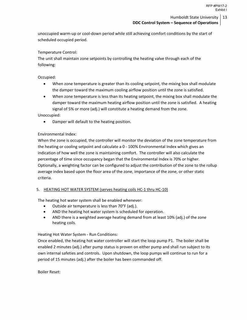
unoccupied warm‐up or cool‐down period while still achieving comfort conditions by the start of
scheduled occupied period.
Temperature Control:
The unit shall maintain zone setpoints by controlling the heating valve through each of the
following:
Occupied:
When zone temperature is greater than its cooling setpoint, the mixing box shall modulate
the damper toward the maximum cooling airflow position until the zone is satisfied.
When zone temperature is less than its heating setpoint, the mixing box shall modulate the
damper toward the maximum heating airflow position until the zone is satisfied. A heating
signal of 5% or more (adj.) will constitute a heating demand from the zone.
Unoccupied:
Damper will default to the heating position.
Environmental Index:
When the zone is occupied, the controller will monitor the deviation of the zone temperature from
the heating or cooling setpoint and calculate a 0 ‐ 100% Environmental Index which gives an
indication of how well the zone is maintaining comfort. The controller will also calculate the
percentage of time since occupancy began that the Environmental Index is 70% or higher.
Optionally, a weighting factor can be configured to adjust the contribution of the zone to the rollup
average index based upon the floor area of the zone, importance of the zone, or other static
criteria.
5. HEATING HOT WATER SYSTEM (serves heating coils HC‐1 thru HC‐10)
The heating hot water system shall be enabled whenever:
Outside air temperature is less than 70°F (adj.).
AND the heating hot water system is scheduled for operation.
AND there is a weighted average heating demand from at least 10% (adj.) of the zone heating coils.
Heating Hot Water System ‐ Run Conditions:
Once enabled, the heating hot water controller will start the loop pump P1. The boiler shall be
enabled 2 minutes (adj.) after pump status is proven on either pump and shall run subject to its
own internal safeties and controls. Upon shutdown, the loop pumps will continue to run for a
period of 15 minutes (adj.) after the boiler has been commanded off.
Boiler Reset:
RFP #PW17-2 Exhibit I
Humboldt State University DDC Control System – Sequence of Operations
14
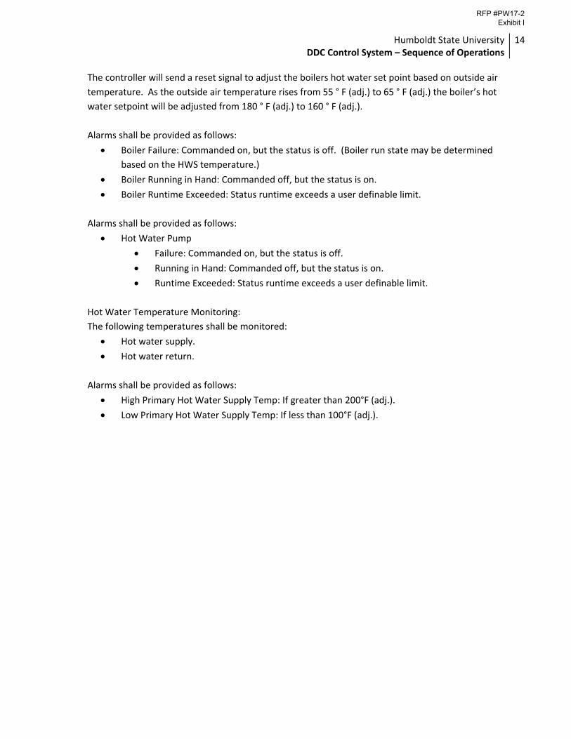
The controller will send a reset signal to adjust the boilers hot water set point based on outside air
temperature. As the outside air temperature rises from 55 ° F (adj.) to 65 ° F (adj.) the boiler’s hot
water setpoint will be adjusted from 180 ° F (adj.) to 160 ° F (adj.).
Alarms shall be provided as follows:
Boiler Failure: Commanded on, but the status is off. (Boiler run state may be determined
based on the HWS temperature.)
Boiler Running in Hand: Commanded off, but the status is on.
Boiler Runtime Exceeded: Status runtime exceeds a user definable limit.
Alarms shall be provided as follows:
Hot Water Pump
Failure: Commanded on, but the status is off.
Running in Hand: Commanded off, but the status is on.
Runtime Exceeded: Status runtime exceeds a user definable limit.
Hot Water Temperature Monitoring:
The following temperatures shall be monitored:
Hot water supply.
Hot water return.
Alarms shall be provided as follows:
High Primary Hot Water Supply Temp: If greater than 200°F (adj.).
Low Primary Hot Water Supply Temp: If less than 100°F (adj.).
RFP #PW17-2 Exhibit I
Humboldt State University DDC Control System – Sequence of Operations
15
SIEMENS HALL 4. AIR HANDLING UNIT SF‐1 & SF‐2 (MIXED AIR DUAL DUCT)
Occupied Mode: The unit shall run whenever it is scheduled for operation by the buildings adjustable weekly operation schedule, or when requested by a minimum 10% (adj.) weighted average demand from the zone boxes due to optimal start or night setback operation.
AHU Optimal Start:
The unit shall start prior to scheduled occupancy based on the time necessary for the zones to
reach their occupied setpoints. The start time shall automatically adjust based on changes in
outside air temperature and zone temperatures. The optimal start logic will have a maximum
unoccupied startup time of 2 hrs (adj.).
Supply Air Smoke Detection: The unit shall shut down and generate an alarm upon receiving a supply air smoke detector status. Supply Fan: Both supply fans SF‐1 and SF‐2 shall run whenever the unit is enabled. Alarms shall be provided as follows:
Supply Fan Failure: Commanded on, but the status is off.
Supply Fan in Hand: Commanded off, but the status is on.
Supply Fan Runtime Exceeded: Status runtime exceeds a user definable limit (adj.). Hot Deck ‐ Heating Supply Air Temperature Setpoint Reset On Outside Air: For future use; the heating valve is not currently used for this unit. The heating supply air temperature setpoint shall reset based on outside air temperature. As outside air temperature drops from 55°F (adj.) to 40°F (adj.) the heating supply air temperature setpoint shall reset upwards from 85°F (adj.) to 110°F (adj.). Hot Deck ‐ Heating Coil Valve: For future use; the heating valve is not currently used for this unit. The controller shall measure the heating supply air temperature and modulate the heating coil valve to maintain the hot deck setpoint. Alarms shall be provided as follows:
High Heating Supply Air Temp: If the heating supply air temperature is greater than 120°F (adj.).
Low Heating Supply Air Temp: If the heating supply air temperature is 5°F (adj.) less than setpoint.
Cold Deck ‐ Cooling Supply Air Temperature Setpoint – Outside Air Reset: Initial cold deck setpoint shall be 55°F (adj.) The cooling supply air temperature setpoint shall reset
RFP #PW17-2 Exhibit I
Humboldt State University DDC Control System – Sequence of Operations
16
based on outside air temperature. As outside air temperature drops from 55°F (adj.) to 30°F (adj.) the cooling supply air temperature setpoint shall reset upwards from 55°F (adj.) to 60°F (adj.). Cold Deck Supply Air Temperature: The controller shall monitor the mixed air temperature and alarms shall be provided as follows:
High Mixed Air Temp: If the cold deck supply air temperature is greater than 90 °F (adj.).
Low Mixed Air Temp: If the cold deck supply air temperature is less than 45°F (adj.). Minimum Outside Air Damper: The minimum outside air damper shall open to its pre‐determined minimum outside air position any time that the unit is occupied. Economizer (modulating outside air and return air dampers): The controller shall measure the mixed air temperature and modulate the outside and return air dampers in sequence to maintain the mixed air temperature at the cold deck temperature setpoint. The economizer shall be enabled whenever:
Outside air temperature is less than 65°F (adj.).
AND the outside air temperature is less than the return air temperature.
AND the supply fan status is on. The economizer shall close whenever:
The economizer is not enabled by the parameters above.
Mixed air temperature drops below 45°F (adj.).
OR on loss of supply fan status.
OR the freeze stat (if present) is on. Minimum Outside Air Ventilation ‐ Carbon Dioxide (CO2) Control: When in the occupied mode, the controller shall measure the return air CO2 concentration and modulate the outside air dampers open on rising CO2 concentrations, overriding normal damper operation to maintain a CO2 setpoint of 850 ppm (adj.). The minimum outside air damper and the outside air damper shall close and the return air damper shall open when the unit is off. Return Air Temperature: The controller shall monitor the return air temperature. Alarms shall be provided as follows:
High Return Air Temp: If the return air temperature is greater than 90°F (adj.).
Low Return Air Temp: If the return air temperature is less than 45°F (adj.).
Duct Pressure Balancing Damper: Differential pressure is measured between the unit’s hot duct and cold duct. During occupied mode, the damper actuator at the hot duct shall modulate to maintain a constant downstream duct differential pressure of 0.0“w.c. (adj.). When the unit is in unoccupied mode, the hot duct balancing damper will open completely.
RFP #PW17-2 Exhibit I
Humboldt State University DDC Control System – Sequence of Operations
17
5. TWO SPEED EXHAUST FANS EF‐1 AND EF‐5 Both exhaust fans shall run on low speed whenever the unit is enabled. Exhaust fans will stage up to high speed as necessary to maintain a building static pressure setpoint of +0.03”w.c. (adj.). Static pressure will be measured centrally in the corridor of each floor and averaged for sequencing of EF‐1 and EF‐5. Exhaust fans will stop during unoccupied modes. Alarms shall be provided as follows:
Exhaust Fan Failure: Commanded on, but the status is off.
Exhaust Fan in Hand: Commanded off, but the status is on.
Exhaust Fan Runtime Exceeded: Status runtime exceeds a user definable limit (adj.). 6. SINGLE SPEED EXHAUST FANS EF‐2 AND EF‐3
The exhaust fans shall be enabled whenever the unit is enabled. Exhaust fans will stop during unoccupied modes. Alarms shall be provided as follows:
Exhaust Fan Failure: Commanded on, but the status is off.
Exhaust Fan in Hand: Commanded off, but the status is on.
Exhaust Fan Runtime Exceeded: Status runtime exceeds a user definable limit (adj.).
7. HEATING HOT WATER SYSTEM / BOILER B‐1
The heating hot water system shall be enabled whenever:
Outside air temperature is less than 70°F (adj.).
AND the heating hot water system is scheduled for operation.
AND there is a weighted average heating demand from at least 10% (adj.) of the zone mixing boxes.
Heating Hot Water System ‐ Run Conditions:
Once enabled, the heating hot water controller will start the lead loop pump. The boiler shall be
enabled 2 minutes (adj.) after pump status is proven on and shall run subject to its own internal
safeties and controls. Upon shutdown, the lead loop pump will continue to run for a period of 15
minutes (adj.) after the boiler has been commanded off.
Boiler Reset:
The controller will send a reset signal to adjust the boilers hot water set point based on outside air
temperature. As the outside air temperature rises from 55 ° F (adj.) to 65 ° F (adj.) the boiler’s hot
water setpoint will be adjusted from 180 ° F (adj.) to 160 ° F (adj.).
Alarms shall be provided as follows:
RFP #PW17-2 Exhibit I
Humboldt State University DDC Control System – Sequence of Operations
18
Boiler Failure: Commanded on, but the status is off. (Boiler run state may be determined
based on the HWS temperature.)
Boiler Running in Hand: Commanded off, but the status is on.
Boiler Runtime Exceeded: Status runtime exceeds a user definable limit.
Hot Water Pump Lead/Lag Operation:
The two hot water pumps shall operate in a lead/lag fashion.
The lead pump shall run first.
On failure of the lead pump, the lag pump shall run and the lead pump shall turn off.
The designated lead pump shall rotate upon one of the following conditions (user selectable):
manually through a software switch
if pump runtime (adj.) is exceeded
daily
weekly
monthly
Alarms shall be provided as follows:
Hot Water Pump X
Failure: Commanded on, but the status is off.
Running in Hand: Commanded off, but the status is on.
Runtime Exceeded: Status runtime exceeds a user definable limit.
Hot Water Temperature Monitoring:
The following temperatures shall be monitored:
Hot water supply.
Hot water return.
Alarms shall be provided as follows:
High Hot Water Supply Temp: If greater than 200°F (adj.).
Low Hot Water Supply Temp: If less than 100°F (adj.).
6. DUAL DUCT ZONE MIXING BOXES
Run Conditions ‐ Scheduled:
The unit shall run according to a user definable time schedule in the following modes:
Occupied Mode: The unit shall maintain
A 75°F (adj.) cooling setpoint
A 68°F (adj.) heating setpoint.
Unoccupied Mode (night setback): The unit shall maintain
RFP #PW17-2 Exhibit I
Humboldt State University DDC Control System – Sequence of Operations
19
A 85°F (adj.) cooling setpoint.
A 55°F (adj.) heating setpoint.
Alarms shall be provided as follows:
High Zone Temp: If the zone temperature is greater than the cooling setpoint by a user
definable amount (adj.).
Low Zone Temp: If the zone temperature is less than the heating setpoint by a user
definable amount (adj.).
Zone Setpoint Adjust:
The occupant shall be able to adjust the zone temperature heating and cooling setpoints at the
zone sensor.
Zone Optimal Start:
The unit shall use an optimal start algorithm for morning start‐up. This algorithm shall minimize the
unoccupied warm‐up or cool‐down period while still achieving comfort conditions by the start of
scheduled occupied period.
Temperature Control:
The unit shall maintain zone setpoints by controlling the airflow through each of the following:
Occupied:
When zone temperature is greater than its cooling setpoint, the mixing box shall modulate
the damper toward the maximum cooling airflow position until the zone is satisfied.
When zone temperature is less than its heating setpoint, the mixing box shall modulate the
damper toward the maximum heating airflow position until the zone is satisfied. A heating
signal of 5% or more (adj.) will constitute a heating demand from the zone
Unoccupied:
Damper will default to the heating position.
Environmental Index:
When the zone is occupied, the controller will monitor the deviation of the zone temperature from
the heating or cooling setpoint and calculate a 0 ‐ 100% Environmental Index which gives an
indication of how well the zone is maintaining comfort. The controller will also calculate the
percentage of time since occupancy began that the Environmental Index is 70% or higher.
Optionally, a weighting factor can be configured to adjust the contribution of the zone to the rollup
average index based upon the floor area of the zone, importance of the zone, or other static
criteria.
RFP #PW17-2 Exhibit I
Humboldt State University DDC Control System – Sequence of Operations
20
STUDENT HEALTH CENTER 1. AIR HANDLING UNIT AH‐1 (MIXED AIR DUAL DUCT)
Occupied Mode: The unit shall run whenever it is scheduled for operation by the buildings adjustable weekly operation schedule, or when requested by a minimum 10% (adj.) weighted average demand from the zone boxes due to optimal start or night setback operation.
AHU Optimal Start:
The unit shall start prior to scheduled occupancy based on the time necessary for the zones to
reach their occupied setpoints. The start time shall automatically adjust based on changes in
outside air temperature and zone temperatures. The optimal start logic will have a maximum
unoccupied startup time of 2 hrs (adj.).
Supply Air Smoke Detection: The unit shall shut down and generate an alarm upon receiving a supply air smoke detector status. Supply Fan: The supply fan shall run whenever the unit is enabled. Alarms shall be provided as follows:
Supply Fan Failure: Commanded on, but the status is off.
Supply Fan in Hand: Commanded off, but the status is on.
Supply Fan Runtime Exceeded: Status runtime exceeds a user definable limit (adj.). Return Fan: The Return fan shall run whenever the unit is enabled. Alarms shall be provided as follows:
Return Fan Failure: Commanded on, but the status is off.
Return Fan in Hand: Commanded off, but the status is on.
Return Fan Runtime Exceeded: Status runtime exceeds a user definable limit (adj.). Hot Deck ‐ Heating Supply Air Temperature Setpoint Reset On Outside Air: The heating supply air temperature setpoint shall reset based on outside air temperature. As outside air temperature drops from 55°F (adj.) to 40°F (adj.) the heating supply air temperature setpoint shall reset upwards from 85°F (adj.) to 110°F (adj.). Hot Deck ‐ Heating Coil Valve: The controller shall measure the heating supply air temperature and modulate the heating coil valve to maintain the hot deck setpoint. Alarms shall be provided as follows:
High Heating Supply Air Temp: If the heating supply air temperature is greater than 120°F (adj.).
Low Heating Supply Air Temp: If the heating supply air temperature is 5°F (adj.) less than setpoint.
RFP #PW17-2 Exhibit I
Humboldt State University DDC Control System – Sequence of Operations
21
Cold Deck ‐ Cooling Supply Air Temperature Setpoint – Outside Air Reset: Initial cold deck setpoint shall be 55°F (adj.) The cooling supply air temperature setpoint shall reset based on outside air temperature. As outside air temperature drops from 55°F (adj.) to 30°F (adj.) the cooling supply air temperature setpoint shall reset upwards from 55°F (adj.) to 60°F (adj.). Cold Deck Supply Air Temperature: The controller shall monitor the mixed air temperature and alarms shall be provided as follows:
High Mixed Air Temp: If the cold deck supply air temperature is greater than 90 °F (adj.).
Low Mixed Air Temp: If the cold deck supply air temperature is less than 45°F (adj.). Economizer (modulating outside air, exhaust air, and return air dampers): The controller shall measure the mixed air temperature and modulate the economizer dampers in sequence to maintain the mixed air temperature at the cold deck temperature setpoint. The economizer shall be enabled whenever:
Outside air temperature is less than 65°F (adj.).
AND the outside air temperature is less than the return air temperature.
AND the supply fan status is on. The economizer shall close whenever:
The economizer is not enabled by the parameters above.
Mixed air temperature drops below 45°F (adj.).
OR on loss of supply fan status.
OR the freeze stat (if present) is on. Minimum Outside Air Ventilation ‐ Carbon Dioxide (CO2) Control: When in the occupied mode, the controller shall measure the return air CO2 concentration and modulate the outside air dampers open on rising CO2 concentrations, overriding normal damper operation to maintain a CO2 setpoint of 850 ppm (adj.). The outside air damper shall close and the return air damper shall open when the unit is off. Return Air Temperature: The controller shall monitor the return air temperature. Alarms shall be provided as follows:
High Return Air Temp: If the return air temperature is greater than 90°F (adj.).
Low Return Air Temp: If the return air temperature is less than 45°F (adj.). 2. DUAL DUCT ZONE MIXING BOXES (typical of 4 zones from AH‐1)
Run Conditions ‐ Scheduled:
The unit shall run according to a user definable time schedule in the following modes:
Occupied Mode: The unit shall maintain
A 75°F (adj.) cooling setpoint
RFP #PW17-2 Exhibit I
Humboldt State University DDC Control System – Sequence of Operations
22
A 68°F (adj.) heating setpoint.
Unoccupied Mode (night setback): The unit shall maintain
A 85°F (adj.) cooling setpoint.
A 55°F (adj.) heating setpoint.
Alarms shall be provided as follows:
High Zone Temp: If the zone temperature is greater than the cooling setpoint by a user
definable amount (adj.).
Low Zone Temp: If the zone temperature is less than the heating setpoint by a user
definable amount (adj.).
Zone Setpoint Adjust:
The occupant shall be able to adjust the zone temperature heating and cooling setpoints at the
zone sensor.
Zone Optimal Start:
The unit shall use an optimal start algorithm for morning start‐up. This algorithm shall minimize the
unoccupied warm‐up or cool‐down period while still achieving comfort conditions by the start of
scheduled occupied period.
Temperature Control:
The unit shall maintain zone setpoints by controlling the airflow through each of the following:
Occupied:
When zone temperature is greater than its cooling setpoint, the mixing box shall modulate
the damper toward the maximum cooling airflow position until the zone is satisfied.
When zone temperature is less than its heating setpoint, the mixing box shall modulate the
damper toward the maximum heating airflow position until the zone is satisfied. A heating
signal of 5% or more (adj.) will constitute a heating demand from the zone
Unoccupied:
Damper will default to the heating position.
Environmental Index:
When the zone is occupied, the controller will monitor the deviation of the zone temperature from
the heating or cooling setpoint and calculate a 0 ‐ 100% Environmental Index which gives an
indication of how well the zone is maintaining comfort. The controller will also calculate the
percentage of time since occupancy began that the Environmental Index is 70% or higher.
Optionally, a weighting factor can be configured to adjust the contribution of the zone to the rollup
average index based upon the floor area of the zone, importance of the zone, or other static
criteria.
RFP #PW17-2 Exhibit I
Humboldt State University DDC Control System – Sequence of Operations
23
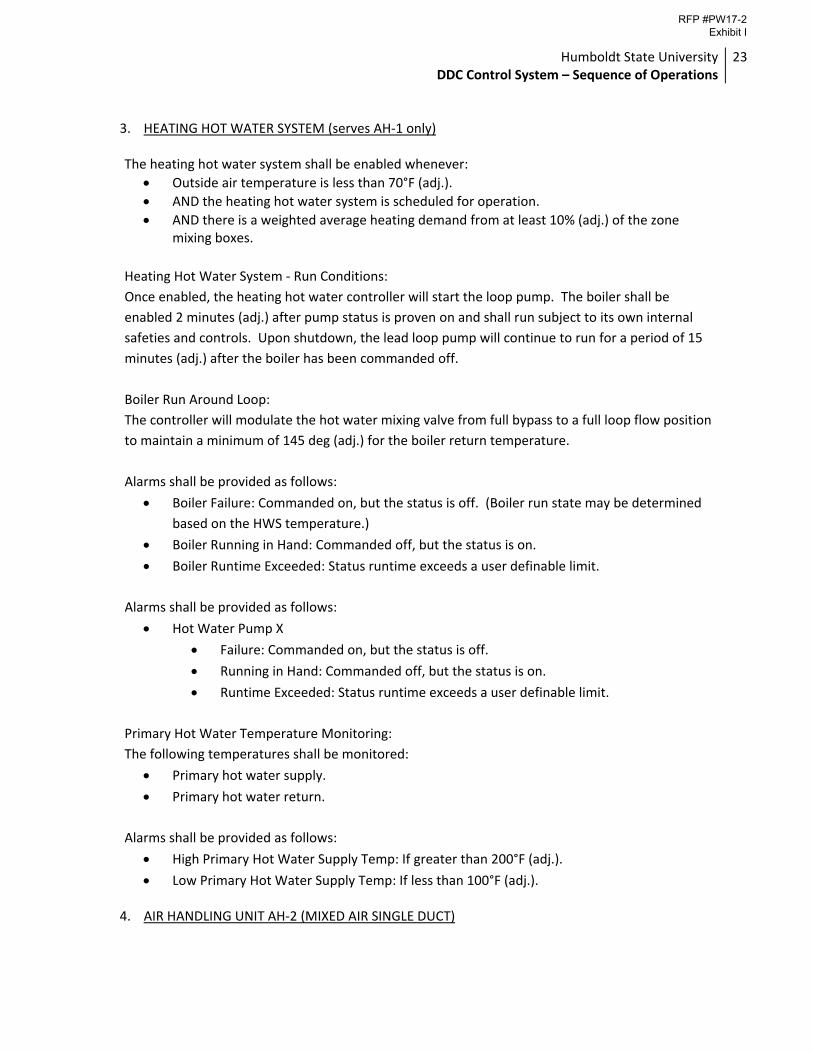
3. HEATING HOT WATER SYSTEM (serves AH‐1 only)
The heating hot water system shall be enabled whenever:
Outside air temperature is less than 70°F (adj.).
AND the heating hot water system is scheduled for operation.
AND there is a weighted average heating demand from at least 10% (adj.) of the zone mixing boxes.
Heating Hot Water System ‐ Run Conditions:
Once enabled, the heating hot water controller will start the loop pump. The boiler shall be
enabled 2 minutes (adj.) after pump status is proven on and shall run subject to its own internal
safeties and controls. Upon shutdown, the lead loop pump will continue to run for a period of 15
minutes (adj.) after the boiler has been commanded off.
Boiler Run Around Loop:
The controller will modulate the hot water mixing valve from full bypass to a full loop flow position
to maintain a minimum of 145 deg (adj.) for the boiler return temperature.
Alarms shall be provided as follows:
Boiler Failure: Commanded on, but the status is off. (Boiler run state may be determined
based on the HWS temperature.)
Boiler Running in Hand: Commanded off, but the status is on.
Boiler Runtime Exceeded: Status runtime exceeds a user definable limit.
Alarms shall be provided as follows:
Hot Water Pump X
Failure: Commanded on, but the status is off.
Running in Hand: Commanded off, but the status is on.
Runtime Exceeded: Status runtime exceeds a user definable limit.
Primary Hot Water Temperature Monitoring:
The following temperatures shall be monitored:
Primary hot water supply.
Primary hot water return.
Alarms shall be provided as follows:
High Primary Hot Water Supply Temp: If greater than 200°F (adj.).
Low Primary Hot Water Supply Temp: If less than 100°F (adj.).
4. AIR HANDLING UNIT AH‐2 (MIXED AIR SINGLE DUCT)
RFP #PW17-2 Exhibit I
Humboldt State University DDC Control System – Sequence of Operations
24
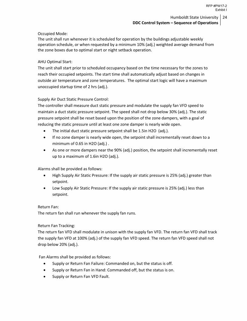
Occupied Mode: The unit shall run whenever it is scheduled for operation by the buildings adjustable weekly operation schedule, or when requested by a minimum 10% (adj.) weighted average demand from the zone boxes due to optimal start or night setback operation.
AHU Optimal Start:
The unit shall start prior to scheduled occupancy based on the time necessary for the zones to
reach their occupied setpoints. The start time shall automatically adjust based on changes in
outside air temperature and zone temperatures. The optimal start logic will have a maximum
unoccupied startup time of 2 hrs (adj.).
Supply Air Duct Static Pressure Control:
The controller shall measure duct static pressure and modulate the supply fan VFD speed to
maintain a duct static pressure setpoint. The speed shall not drop below 30% (adj.). The static
pressure setpoint shall be reset based upon the position of the zone dampers, with a goal of
reducing the static pressure until at least one zone damper is nearly wide open.
The initial duct static pressure setpoint shall be 1.5in H2O (adj.).
If no zone damper is nearly wide open, the setpoint shall incrementally reset down to a
minimum of 0.65 in H2O (adj.) .
As one or more dampers near the 90% (adj.) position, the setpoint shall incrementally reset
up to a maximum of 1.6in H2O (adj.).
Alarms shall be provided as follows:
High Supply Air Static Pressure: If the supply air static pressure is 25% (adj.) greater than
setpoint.
Low Supply Air Static Pressure: If the supply air static pressure is 25% (adj.) less than
setpoint.
Return Fan:
The return fan shall run whenever the supply fan runs.
Return Fan Tracking:
The return fan VFD shall modulate in unison with the supply fan VFD. The return fan VFD shall track
the supply fan VFD at 100% (adj.) of the supply fan VFD speed. The return fan VFD speed shall not
drop below 20% (adj.).
Fan Alarms shall be provided as follows:
Supply or Return Fan Failure: Commanded on, but the status is off.
Supply or Return Fan in Hand: Commanded off, but the status is on.
Supply or Return Fan VFD Fault.
RFP #PW17-2 Exhibit I
Humboldt State University DDC Control System – Sequence of Operations
25
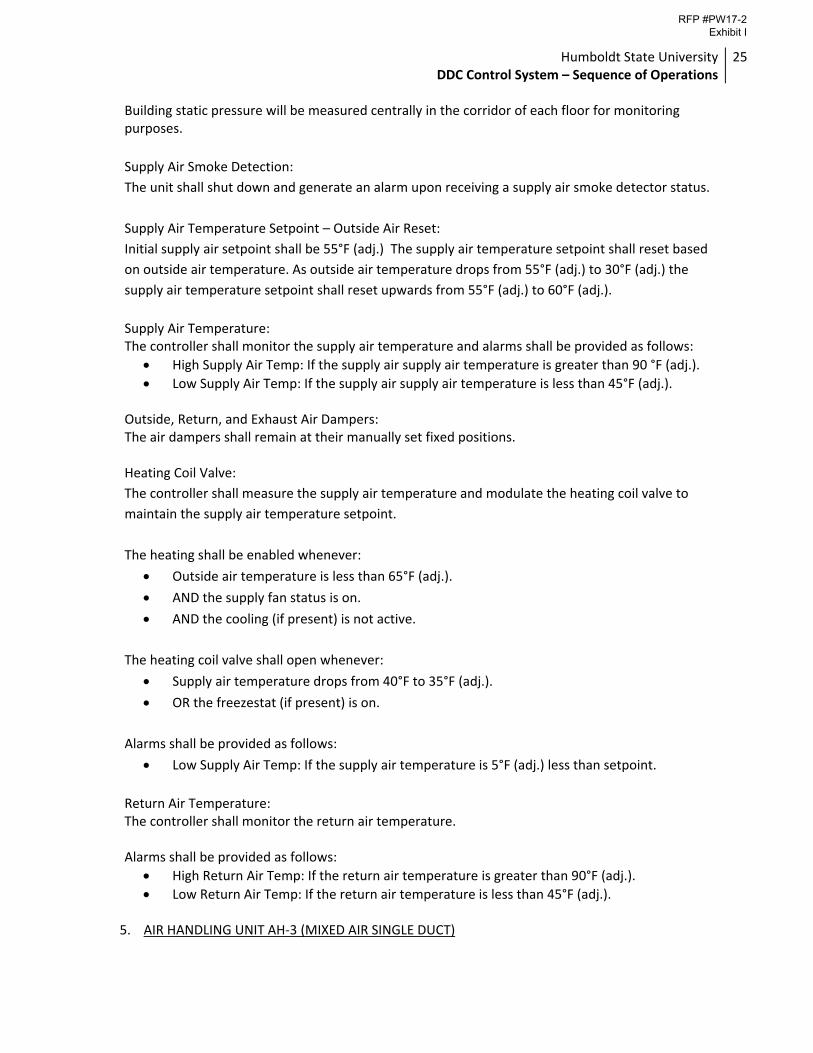
Building static pressure will be measured centrally in the corridor of each floor for monitoring purposes.
Supply Air Smoke Detection:
The unit shall shut down and generate an alarm upon receiving a supply air smoke detector status.
Supply Air Temperature Setpoint – Outside Air Reset:
Initial supply air setpoint shall be 55°F (adj.) The supply air temperature setpoint shall reset based
on outside air temperature. As outside air temperature drops from 55°F (adj.) to 30°F (adj.) the
supply air temperature setpoint shall reset upwards from 55°F (adj.) to 60°F (adj.).
Supply Air Temperature: The controller shall monitor the supply air temperature and alarms shall be provided as follows:
High Supply Air Temp: If the supply air supply air temperature is greater than 90 °F (adj.).
Low Supply Air Temp: If the supply air supply air temperature is less than 45°F (adj.). Outside, Return, and Exhaust Air Dampers: The air dampers shall remain at their manually set fixed positions. Heating Coil Valve:
The controller shall measure the supply air temperature and modulate the heating coil valve to
maintain the supply air temperature setpoint.
The heating shall be enabled whenever:
Outside air temperature is less than 65°F (adj.).
AND the supply fan status is on.
AND the cooling (if present) is not active.
The heating coil valve shall open whenever:
Supply air temperature drops from 40°F to 35°F (adj.).
OR the freezestat (if present) is on.
Alarms shall be provided as follows:
Low Supply Air Temp: If the supply air temperature is 5°F (adj.) less than setpoint.
Return Air Temperature: The controller shall monitor the return air temperature. Alarms shall be provided as follows:
High Return Air Temp: If the return air temperature is greater than 90°F (adj.).
Low Return Air Temp: If the return air temperature is less than 45°F (adj.).
5. AIR HANDLING UNIT AH‐3 (MIXED AIR SINGLE DUCT)
RFP #PW17-2 Exhibit I
Humboldt State University DDC Control System – Sequence of Operations
26
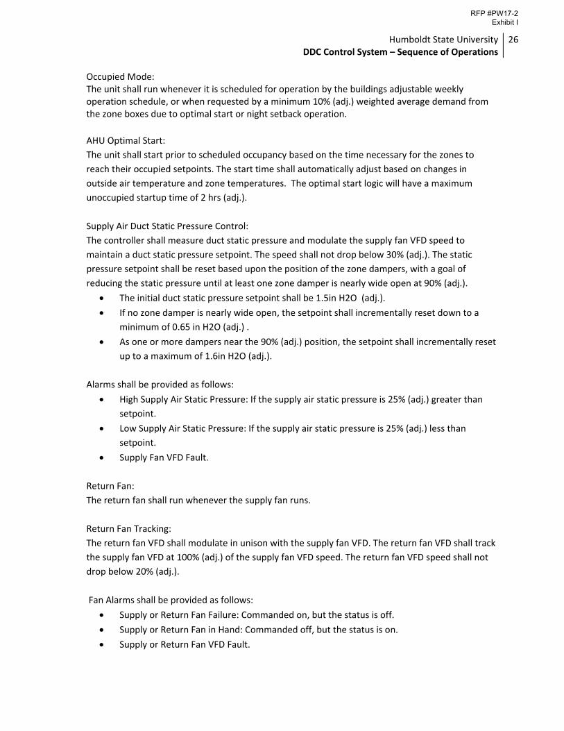
Occupied Mode: The unit shall run whenever it is scheduled for operation by the buildings adjustable weekly operation schedule, or when requested by a minimum 10% (adj.) weighted average demand from the zone boxes due to optimal start or night setback operation.
AHU Optimal Start:
The unit shall start prior to scheduled occupancy based on the time necessary for the zones to
reach their occupied setpoints. The start time shall automatically adjust based on changes in
outside air temperature and zone temperatures. The optimal start logic will have a maximum
unoccupied startup time of 2 hrs (adj.).
Supply Air Duct Static Pressure Control:
The controller shall measure duct static pressure and modulate the supply fan VFD speed to
maintain a duct static pressure setpoint. The speed shall not drop below 30% (adj.). The static
pressure setpoint shall be reset based upon the position of the zone dampers, with a goal of
reducing the static pressure until at least one zone damper is nearly wide open at 90% (adj.).
The initial duct static pressure setpoint shall be 1.5in H2O (adj.).
If no zone damper is nearly wide open, the setpoint shall incrementally reset down to a
minimum of 0.65 in H2O (adj.) .
As one or more dampers near the 90% (adj.) position, the setpoint shall incrementally reset
up to a maximum of 1.6in H2O (adj.).
Alarms shall be provided as follows:
High Supply Air Static Pressure: If the supply air static pressure is 25% (adj.) greater than
setpoint.
Low Supply Air Static Pressure: If the supply air static pressure is 25% (adj.) less than
setpoint.
Supply Fan VFD Fault.
Return Fan:
The return fan shall run whenever the supply fan runs.
Return Fan Tracking:
The return fan VFD shall modulate in unison with the supply fan VFD. The return fan VFD shall track
the supply fan VFD at 100% (adj.) of the supply fan VFD speed. The return fan VFD speed shall not
drop below 20% (adj.).
Fan Alarms shall be provided as follows:
Supply or Return Fan Failure: Commanded on, but the status is off.
Supply or Return Fan in Hand: Commanded off, but the status is on.
Supply or Return Fan VFD Fault.
RFP #PW17-2 Exhibit I
Humboldt State University DDC Control System – Sequence of Operations
27
Supply Air Smoke Detection:
The unit shall shut down and generate an alarm upon receiving a supply air smoke detector status.
Supply Air Temperature Setpoint – Outside Air Reset:
Initial supply air setpoint shall be 55°F (adj.) The supply air temperature setpoint shall reset based
on outside air temperature. As outside air temperature drops from 55°F (adj.) to 30°F (adj.) the
supply air temperature setpoint shall reset upwards from 55°F (adj.) to 60°F (adj.).
Supply Air Temperature: The controller shall monitor the supply air temperature and alarms shall be provided as follows:
High Supply Air Temp: If the supply air supply air temperature is greater than 90 °F (adj.).
Low Supply Air Temp: If the supply air supply air temperature is less than 45°F (adj.). Outside Air Damper: The outside air damper shall open to its pre‐determined minimum outside air position any time that the unit is occupied. Economizer (modulating outside air, exhaust air, and return air dampers): The controller shall measure the supply air temperature and modulate the economizer dampers in sequence to maintain the supply air temperature at the supply air temperature setpoint. The economizer shall be enabled whenever:
Outside air temperature is less than 65°F (adj.).
AND the outside air temperature is less than the return air temperature.
AND the supply fan status is on. The economizer shall close whenever:
The economizer is not enabled by the parameters above.
Mixed air temperature drops below 45°F (adj.).
OR on loss of supply fan status.
OR the freeze stat (if present) is on.
Heating Coil Valve:
During occupied hours, the controller shall measure the supply air temperature and modulate the
heating coil valve to maintain the supply air temperature setpoint. The heating valve shall close
when the air handler is off.
The heating shall be enabled whenever:
Outside air temperature is less than 65°F (adj.).
AND the supply fan status is on.
AND the cooling (if present) is not active.
The heating coil valve shall open whenever:
RFP #PW17-2 Exhibit I
Humboldt State University DDC Control System – Sequence of Operations
28
Supply air temperature drops from 40°F to 35°F (adj.).
OR the freezestat (if present) is on.
Alarms shall be provided as follows:
Low Supply Air Temp: If the supply air temperature is 5°F (adj.) less than setpoint.
Minimum Outside Air Ventilation ‐ Carbon Dioxide (CO2) Control: When in the occupied mode, the controller shall measure the return air CO2 concentration and modulate the outside air dampers open on rising CO2 concentrations, overriding normal damper operation to maintain a CO2 setpoint of 850 ppm (adj.). The outside air damper and the exhaust air damper shall close and the return air damper shall open when the unit is off. Return Air Temperature: The controller shall monitor the return air temperature. Alarms shall be provided as follows:
High Return Air Temp: If the return air temperature is greater than 90°F (adj.).
Low Return Air Temp: If the return air temperature is less than 45°F (adj.).
6. SINGLE DUCT VAV BOX WITH REHEAT COIL:
Run Conditions ‐ Scheduled:
The unit shall run according to a user definable time schedule in the following modes:
Occupied Mode: The unit shall maintain
A 75°F (adj.) cooling setpoint .
A 70°F (adj.) heating setpoint.
Unoccupied Mode (night setback): The unit shall maintain
A 85°F (adj.) cooling setpoint.
A 55°F (adj.) heating setpoint.
Alarms shall be provided as follows:
High Zone Temp: If the zone temperature is greater than the cooling setpoint by a user
definable amount (adj.).
Low Zone Temp: If the zone temperature is less than the heating setpoint by a user
definable amount (adj.).
Zone Setpoint Adjust:
The occupant shall be able to adjust the zone temperature heating and cooling setpoints at the
zone sensor.
RFP #PW17-2 Exhibit I
Humboldt State University DDC Control System – Sequence of Operations
29
Zone Optimal Start:
The unit shall use an optimal start algorithm for morning start‐up. This algorithm shall minimize the
unoccupied warm‐up or cool‐down period while still achieving comfort conditions by the start of
scheduled occupied period.
Variable Volume Terminal Unit ‐ Position Control (Pressure Dependant):
The unit shall maintain zone setpoints by controlling the damper through one of the following:
Occupied:
When zone temperature is greater than its cooling setpoint, the zone damper shall
modulate between the minimum damper position (adj.) and the maximum cooling damper
position (adj.) until the zone is satisfied.
When the zone temperature is between the cooling setpoint and the heating setpoint, the
zone damper shall maintain the minimum damper position to give the required zone
ventilation (adj.).
When zone temperature is less than its heating setpoint, the controller shall enable
hydronic heating to maintain the zone temperature at its heating setpoint. Once the
heating valve has reached the fully open position, if warm air is available from the AHU, the
zone damper shall modulate between the minimum damper position (adj.) and the
maximum heating damper position (adj.) until the zone is satisfied.
Unoccupied:
When the zone is unoccupied the zone damper shall close.
Reheat Coil Valve:
The controller shall measure the zone temperature and modulate the reheat coil valve open on
dropping temperature to maintain its heating setpoint. The reheat valve shall close when the zone
is unoccupied.
Reheat ‐ High Discharge Air Temperature Limit:
The controller shall measure the discharge air temperature and limit reheating if the discharge air
temperature is more than 95°F (adj.).
Alarms shall be provided as follows:
High Discharge Air Temp: If the discharge air temperature is greater than 120°F (adj.).
Low Discharge Air Temp: If the discharge air temperature is less than 40°F (adj.).
Environmental Index: When the zone is occupied, the controller will monitor the deviation of the zone temperature from the heating or cooling setpoint and calculate a 0 ‐ 100% Environmental Index which gives an
RFP #PW17-2 Exhibit I
Humboldt State University DDC Control System – Sequence of Operations
30
indication of how well the zone is maintaining comfort. The controller will also calculate the percentage of time since occupancy began that the Environmental Index is 70% or higher. 7. HEATING HOT WATER SYSTEM (serves AH‐2, AH‐3, and VAV Boxes)
The heating hot water system shall be enabled whenever:
Outside air temperature is less than 70°F (adj.).
AND the heating hot water system is scheduled for operation.
AND there is a heating demand from AH‐2, AH‐3, or a weighted average heating demand from at least 10% (adj.) of the zone VAV boxes.
Heating Hot Water System ‐ Run Conditions:
Once enabled, the heating hot water controller will start the parallel loop pumps P1 and P2. The
boiler shall be enabled 2 minutes (adj.) after pump status is proven on either pump and shall run
subject to its own internal safeties and controls. Upon shutdown, the loop pumps will continue to
run for a period of 15 minutes (adj.) after the boiler has been commanded off.
Boiler Mixing Loop:
The controller will modulate the hot water mixing valve from full boiler flow to a minimum bypass
position of 20% (adj.) to maintain 180 deg (adj.) for the supply temperature.
Alarms shall be provided as follows:
Boiler Failure: Commanded on, but the status is off. (Boiler run state may be determined
based on the HWS temperature.)
Boiler Running in Hand: Commanded off, but the status is on.
Boiler Runtime Exceeded: Status runtime exceeds a user definable limit.
Alarms shall be provided as follows:
Hot Water Pump X
Failure: Commanded on, but the status is off.
Running in Hand: Commanded off, but the status is on.
Runtime Exceeded: Status runtime exceeds a user definable limit.
Hot Water Temperature Monitoring:
The following temperatures shall be monitored:
Hot water supply.
Hot water return.
Alarms shall be provided as follows:
High Primary Hot Water Supply Temp: If greater than 200°F (adj.).
Low Primary Hot Water Supply Temp: If less than 100°F (adj.).
RFP #PW17-2 Exhibit I
Humboldt State University DDC Control System – Sequence of Operations
31
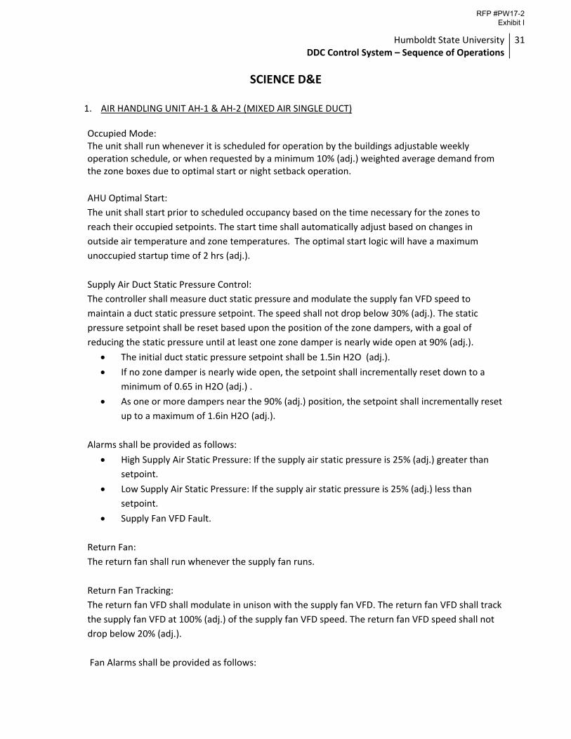
SCIENCE D&E 1. AIR HANDLING UNIT AH‐1 & AH‐2 (MIXED AIR SINGLE DUCT)
Occupied Mode: The unit shall run whenever it is scheduled for operation by the buildings adjustable weekly operation schedule, or when requested by a minimum 10% (adj.) weighted average demand from the zone boxes due to optimal start or night setback operation.
AHU Optimal Start:
The unit shall start prior to scheduled occupancy based on the time necessary for the zones to
reach their occupied setpoints. The start time shall automatically adjust based on changes in
outside air temperature and zone temperatures. The optimal start logic will have a maximum
unoccupied startup time of 2 hrs (adj.).
Supply Air Duct Static Pressure Control:
The controller shall measure duct static pressure and modulate the supply fan VFD speed to
maintain a duct static pressure setpoint. The speed shall not drop below 30% (adj.). The static
pressure setpoint shall be reset based upon the position of the zone dampers, with a goal of
reducing the static pressure until at least one zone damper is nearly wide open at 90% (adj.).
The initial duct static pressure setpoint shall be 1.5in H2O (adj.).
If no zone damper is nearly wide open, the setpoint shall incrementally reset down to a
minimum of 0.65 in H2O (adj.) .
As one or more dampers near the 90% (adj.) position, the setpoint shall incrementally reset
up to a maximum of 1.6in H2O (adj.).
Alarms shall be provided as follows:
High Supply Air Static Pressure: If the supply air static pressure is 25% (adj.) greater than
setpoint.
Low Supply Air Static Pressure: If the supply air static pressure is 25% (adj.) less than
setpoint.
Supply Fan VFD Fault.
Return Fan:
The return fan shall run whenever the supply fan runs.
Return Fan Tracking:
The return fan VFD shall modulate in unison with the supply fan VFD. The return fan VFD shall track
the supply fan VFD at 100% (adj.) of the supply fan VFD speed. The return fan VFD speed shall not
drop below 20% (adj.).
Fan Alarms shall be provided as follows:
RFP #PW17-2 Exhibit I
Humboldt State University DDC Control System – Sequence of Operations
32
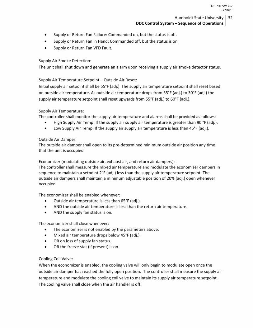
Supply or Return Fan Failure: Commanded on, but the status is off.
Supply or Return Fan in Hand: Commanded off, but the status is on.
Supply or Return Fan VFD Fault.
Supply Air Smoke Detection:
The unit shall shut down and generate an alarm upon receiving a supply air smoke detector status.
Supply Air Temperature Setpoint – Outside Air Reset:
Initial supply air setpoint shall be 55°F (adj.) The supply air temperature setpoint shall reset based
on outside air temperature. As outside air temperature drops from 55°F (adj.) to 30°F (adj.) the
supply air temperature setpoint shall reset upwards from 55°F (adj.) to 60°F (adj.).
Supply Air Temperature: The controller shall monitor the supply air temperature and alarms shall be provided as follows:
High Supply Air Temp: If the supply air supply air temperature is greater than 90 °F (adj.).
Low Supply Air Temp: If the supply air supply air temperature is less than 45°F (adj.). Outside Air Damper: The outside air damper shall open to its pre‐determined minimum outside air position any time that the unit is occupied. Economizer (modulating outside air, exhaust air, and return air dampers): The controller shall measure the mixed air temperature and modulate the economizer dampers in sequence to maintain a setpoint 2°F (adj.) less than the supply air temperature setpoint. The outside air dampers shall maintain a minimum adjustable position of 20% (adj.) open whenever occupied. The economizer shall be enabled whenever:
Outside air temperature is less than 65°F (adj.).
AND the outside air temperature is less than the return air temperature.
AND the supply fan status is on. The economizer shall close whenever:
The economizer is not enabled by the parameters above.
Mixed air temperature drops below 45°F (adj.).
OR on loss of supply fan status.
OR the freeze stat (if present) is on.
Cooling Coil Valve:
When the economizer is enabled, the cooling valve will only begin to modulate open once the
outside air damper has reached the fully open position. The controller shall measure the supply air
temperature and modulate the cooling coil valve to maintain its supply air temperature setpoint.
The cooling valve shall close when the air handler is off.
RFP #PW17-2 Exhibit I
Humboldt State University DDC Control System – Sequence of Operations
33
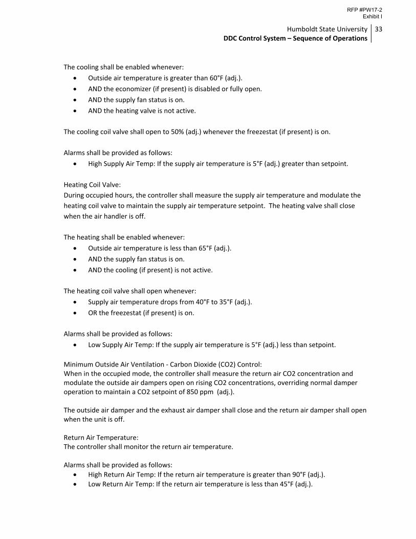
The cooling shall be enabled whenever:
Outside air temperature is greater than 60°F (adj.).
AND the economizer (if present) is disabled or fully open.
AND the supply fan status is on.
AND the heating valve is not active.
The cooling coil valve shall open to 50% (adj.) whenever the freezestat (if present) is on.
Alarms shall be provided as follows:
High Supply Air Temp: If the supply air temperature is 5°F (adj.) greater than setpoint.
Heating Coil Valve:
During occupied hours, the controller shall measure the supply air temperature and modulate the
heating coil valve to maintain the supply air temperature setpoint. The heating valve shall close
when the air handler is off.
The heating shall be enabled whenever:
Outside air temperature is less than 65°F (adj.).
AND the supply fan status is on.
AND the cooling (if present) is not active.
The heating coil valve shall open whenever:
Supply air temperature drops from 40°F to 35°F (adj.).
OR the freezestat (if present) is on.
Alarms shall be provided as follows:
Low Supply Air Temp: If the supply air temperature is 5°F (adj.) less than setpoint.
Minimum Outside Air Ventilation ‐ Carbon Dioxide (CO2) Control: When in the occupied mode, the controller shall measure the return air CO2 concentration and modulate the outside air dampers open on rising CO2 concentrations, overriding normal damper operation to maintain a CO2 setpoint of 850 ppm (adj.). The outside air damper and the exhaust air damper shall close and the return air damper shall open when the unit is off. Return Air Temperature: The controller shall monitor the return air temperature. Alarms shall be provided as follows:
High Return Air Temp: If the return air temperature is greater than 90°F (adj.).
Low Return Air Temp: If the return air temperature is less than 45°F (adj.).
RFP #PW17-2 Exhibit I
Humboldt State University DDC Control System – Sequence of Operations
34
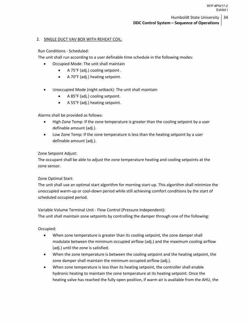
2. SINGLE DUCT VAV BOX WITH REHEAT COIL:
Run Conditions ‐ Scheduled:
The unit shall run according to a user definable time schedule in the following modes:
Occupied Mode: The unit shall maintain
A 75°F (adj.) cooling setpoint .
A 70°F (adj.) heating setpoint.
Unoccupied Mode (night setback): The unit shall maintain
A 85°F (adj.) cooling setpoint.
A 55°F (adj.) heating setpoint.
Alarms shall be provided as follows:
High Zone Temp: If the zone temperature is greater than the cooling setpoint by a user
definable amount (adj.).
Low Zone Temp: If the zone temperature is less than the heating setpoint by a user
definable amount (adj.).
Zone Setpoint Adjust:
The occupant shall be able to adjust the zone temperature heating and cooling setpoints at the
zone sensor.
Zone Optimal Start:
The unit shall use an optimal start algorithm for morning start‐up. This algorithm shall minimize the
unoccupied warm‐up or cool‐down period while still achieving comfort conditions by the start of
scheduled occupied period.
Variable Volume Terminal Unit ‐ Flow Control (Pressure Independent):
The unit shall maintain zone setpoints by controlling the damper through one of the following:
Occupied:
When zone temperature is greater than its cooling setpoint, the zone damper shall
modulate between the minimum occupied airflow (adj.) and the maximum cooling airflow
(adj.) until the zone is satisfied.
When the zone temperature is between the cooling setpoint and the heating setpoint, the
zone damper shall maintain the minimum occupied airflow (adj.).
When zone temperature is less than its heating setpoint, the controller shall enable
hydronic heating to maintain the zone temperature at its heating setpoint. Once the
heating valve has reached the fully open position, if warm air is available from the AHU, the
RFP #PW17-2 Exhibit I
Humboldt State University DDC Control System – Sequence of Operations
35
zone damper shall modulate between the minimum occupied airflow (adj.) and the
maximum heating airflow (adj.) until the zone is satisfied.
Unoccupied:
When the zone is unoccupied the zone damper shall close.
Reheat Coil Valve:
The controller shall measure the zone temperature and modulate the reheat coil valve open on
dropping temperature to maintain its heating setpoint. The reheat valve shall close when the zone
is unoccupied.
Reheat ‐ High Discharge Air Temperature Limit:
The controller shall measure the discharge air temperature and limit reheating if the discharge air
temperature is more than 95°F (adj.).
Discharge Air Temperature:
The controller shall monitor the discharge air temperature.
Alarms shall be provided as follows:
High Discharge Air Temp: If the discharge air temperature is greater than 120°F (adj.).
Low Discharge Air Temp: If the discharge air temperature is less than 40°F (adj.).
Environmental Index: When the zone is occupied, the controller will monitor the deviation of the zone temperature from the heating or cooling setpoint and calculate a 0 ‐ 100% Environmental Index which gives an indication of how well the zone is maintaining comfort. The controller will also calculate the percentage of time since occupancy began that the Environmental Index is 70% or higher. 3. HEATING HOT WATER SYSTEM
The heating hot water system shall be enabled whenever:
Outside air temperature is less than 70°F (adj.).
AND the heating hot water system is scheduled for operation.
AND there is a heating demand from AH‐1, AH‐2, or a weighted average heating demand from at least 10% (adj.) of the zone VAV boxes.
OR “Science E” is scheduled for night time heating.
Heating Hot Water System ‐ Run Conditions:
Once enabled, the heating hot water controller will start the lead loop pump. The boiler shall be
enabled 2 minutes (adj.) after pump status is proven on and shall run subject to its own internal
safeties and controls. Upon shutdown, the lead loop pump will continue to run for a period of 15
minutes (adj.) after the boiler has been commanded off.
RFP #PW17-2 Exhibit I
Humboldt State University DDC Control System – Sequence of Operations
36
Alarms shall be provided as follows:
Boiler Failure: Commanded on, but the status is off. (Boiler run state may be determined
based on the HWS temperature.)
Boiler Running in Hand: Commanded off, but the status is on.
Boiler Runtime Exceeded: Status runtime exceeds a user definable limit.
Hot Water Pump Lead/Lag Operation:
The two hot water pumps shall operate in a lead/lag fashion.
The lead pump shall run first.
On failure of the lead pump, the lag pump shall run and the lead pump shall turn off.
The designated lead pump shall rotate upon one of the following conditions (user selectable):
manually through a software switch
if pump runtime (adj.) is exceeded
daily
weekly
monthly
Alarms shall be provided as follows:
Hot Water Pump X
Failure: Commanded on, but the status is off.
Running in Hand: Commanded off, but the status is on.
Runtime Exceeded: Status runtime exceeds a user definable limit.
“Science D” Isolation Valve:
Science D Isolation valve shall close when there is no heating demand from the building.
BTU Meters:
Existing energy meters will read flow and temperature splits to calculate BTU load for the main
hydronic heating loop and for Building E.
Hot Water Temperature Monitoring:
The following temperatures shall be monitored:
Hot water supply.
Hot water return.
Building supply and return. (Science E)
Alarms shall be provided as follows:
High Primary Hot Water Supply Temp: If greater than 200°F (adj.).
Low Primary Hot Water Supply Temp: If less than 100°F (adj.).
RFP #PW17-2 Exhibit I
Humboldt State University DDC Control System – Sequence of Operations
37
4. CHILLED WATER SYSTEM
The chilled water system shall be enabled whenever:
Outside air temperature is greater than 65°F (adj.).
AND the chilled water system is scheduled for operation.
AND there is a cooling demand from AH‐1 or AH‐2.
Chilled Water System ‐ Run Conditions:
Once enabled, the chilled water controller will start the lead loop pump. The chiller shall be
enabled 2 minutes (adj.) after pump status is proven on and shall run subject to its own internal
safeties and controls. Upon shutdown, the lead loop pump will continue to run for a period of 15
minutes (adj.) after the chiller has been commanded off.
Alarms shall be provided as follows:
Chiller Failure: Commanded on, but the status is off. (Chiller run state may be determined
based on the CHWS temperature.)
Chiller Running in Hand: Commanded off, but the status is on.
Chiller Runtime Exceeded: Status runtime exceeds a user definable limit.
Chilled Water Pump Lead/Lag Operation:
The two chilled water pumps shall operate in a lead/lag fashion.
The lead pump shall run first.
On failure of the lead pump, the lag pump shall run and the lead pump shall turn off.
The designated lead pump shall rotate upon one of the following conditions (user selectable):
manually through a software switch
if pump runtime (adj.) is exceeded
daily
weekly
monthly
Alarms shall be provided as follows:
Chilled Water Pump X
Failure: Commanded on, but the status is off.
Running in Hand: Commanded off, but the status is on.
Runtime Exceeded: Status runtime exceeds a user definable limit.
Chilled Water Temperature Monitoring:
The following temperatures shall be monitored:
Chilled water supply.
Chilled water return.
RFP #PW17-2 Exhibit I
Humboldt State University DDC Control System – Sequence of Operations
38
Alarms shall be provided as follows:
High Primary Chilled Water Supply Temp: If greater than 55°F (adj.).
Low Primary Chilled Water Supply Temp: If less than 36°F (adj.).
RFP #PW17-2 Exhibit I


![Topics: Sequence Sequences Index into a sequence [] notation Slicing and other operations](https://img.pdfslide.us/doc/110x75/56649ed95503460f94be86ae/topics-sequence-sequences-index-into-a-sequence-notation-slicing-and-other.jpg)
![[Alexander Von Humboldt] Letters of Alexander Von Humboldt](https://img.pdfslide.us/doc/110x75/577c79791a28abe05492c6ea/alexander-von-humboldt-letters-of-alexander-von-humboldt.jpg)