Embed Size (px)
Citation preview

3,350+OPEN ACCESS BOOKS
108,000+INTERNATIONAL
AUTHORS AND EDITORS115+ MILLION
DOWNLOADS
BOOKSDELIVERED TO
151 COUNTRIES
AUTHORS AMONG
TOP 1%MOST CITED SCIENTIST
12.2%AUTHORS AND EDITORS
FROM TOP 500 UNIVERSITIES
Selection of our books indexed in theBook Citation Index in Web of Science™
Core Collection (BKCI)
Chapter from the book Advanced Transmiss ion Techniques in WiMAXDownloaded from: http://www.intechopen.com/books/advanced-transmiss ion-techniques-in-wimax
PUBLISHED BY
World's largest Science,Technology & Medicine
Open Access book publisher
Interested in publishing with IntechOpen?Contact us at [email protected]
2
CPW-Fed Antennas for WiFi and WiMAX
Sarawuth Chaimool and Prayoot Akkaraekthalin Wireless Communication Research Group (WCRG), Electrical Engineering,
Faculty of Engineering, King Mongkut’s University of Technology North Bangkok, Thailand
1. Introduction
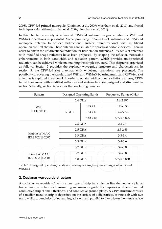
Recently, several researchers have devoted large efforts to develop antennas that satisfy the demands of the wireless communication industry for improving performances, especially in term of multiband operations and miniaturization. As a matter of fact, the design and development of a single antenna working in two or more frequency bands, such as in wireless local area network (WLAN) or WiFi and worldwide interoperability for microwave access (WiMAX) is generally not an easy task. The IEEE 802.11 WLAN standard allocates the license-free spectrum of 2.4 GHz (2.40-2.48 GHz), 5.2 GHz (5.15-5.35 GHz) and 5.8 GHz (5.725-5.825 GHz). WiMAX, based on the IEEE 802.16 standard, has been evaluated by companies for last mile connectivity, which can reach a theoretical up to 30 mile radius coverage. The WiMAX forum has published three licenses spectrum profiles, namely the 2.3 (2.3-2.4 GHz), 2.5 GHz (2.495-2.69 GHz) and 3.5 GHz (3.5-3.6 GHz) varying country to country. Many people expect WiMAX to emerge as another technology especially WiFi that may be adopted for handset devices and base station in the near future. The eleven standardized WiFi and WiMAX operating bands are listed in Table I.
Consequently, the research and manufacturing of both indoor and outdoor transmission equipment and devices fulfilling the requirements of these WiFi and WiMAX standards have increased since the idea took place in the technical and industrial community. An antenna serves as one of the critical component in any wireless communication system. As mentioned above, the design and development of a single antenna working in wideband or more frequency bands, called multiband antenna, is generally not an easy task. To answer these challenges, many antennas with wideband and/or multiband performances have been published in open literatures. The popular antenna for such applications is microstrip antenna (MSA) where several designs of multiband MSAs have been reported. Another important candidate, which may complete favorably with microstrip, is coplanar waveguide (CPW). Antennas using CPW-fed line also have many attractive features including low-radiation loss, less dispersion, easy integration for monolithic microwave circuits (MMICs) and a simple configuration with single metallic layer, since no backside processing is required for integration of devices. Therefore, the designs of CPW-fed antennas have recently become more and more attractive. One of the main issues with CPW-fed antennas is to provide an easy impedance matching to the CPW-fed line. In order to obtain multiband and broadband operations, several techniques have been reported in the literatures based on CPW-fed slot antennas (Chaimool et al., 2004, 2005, 2008; Sari-Kha et al., 2006; Jirasakulporn,
www.intechopen.com
Advanced Transmission Techniques in WiMAX
20
2008), CPW-fed printed monopole (Chaimool et al., 2009; Moekham et al., 2011) and fractal techniques (Mahatthanajatuphat et al., 2009; Honghara et al., 2011).
In this chapter, a variety of advanced CPW-fed antenna designs suitable for WiFi and
WiMAX operations is presented. Some promising CPW-fed slot antennas and CPW-fed
monopole antenna to achieve bidirectional and/or omnidirectional with multiband
operation are first shown. These antennas are suitable for practical portable devices. Then, in
order to obtain the unidirectional radiation for base station antennas, CPW-fed slot antennas
with modified shape reflectors have been proposed. By shaping the reflector, noticeable
enhancements in both bandwidth and radiation pattern, which provides unidirectional
radiation, can be achieved while maintaining the simple structure. This chapter is organized
as follows. Section 2 provides the coplanar waveguide structure and characteristics. In
section 3, the CPW-fed slot antennas with wideband operations are presented. The
possibility of covering the standardized WiFi and WiMAX by using multiband CPW-fed slot
antennas is explored in section 4. In order to obtain unidirectional radiation patterns, CPW-
fed slot antennas with modified reflectors and metasurface are designed and discussed in
section 5. Finally, section 6 provides the concluding remarks.
System Designed Operating Bands Frequency Range (GHz)
WiFi IEEE 802.11
2.4 GHz 2.4-2.485
5 GHz
5.2 GHz 5.15-5.35
5.5 GHz 5.47-5.725
5.8 GHz 5.725-5.875
Mobile WiMAX IEEE 802.16 2005
2.3 GHz 2.3-2.4
2.5 GHz 2.5-2.69
3.3 GHz 3.3-3.4
3.5 GHz 3.4-3.6
3.7 GHz 3.6-3.8
Fixed WiMAX IEEE 802.16 2004
3.7 GHz 3.6-3.8
5.8 GHz 5.725-5.850
Table 1. Designed operating bands and corresponding frequency ranges of WiFi and WiMAX
2. Coplanar waveguide structure
A coplanar waveguide (CPW) is a one type of strip transmission line defined as a planar transmission structure for transmitting microwave signals. It comprises of at least one flat conductive strip of small thickness, and conductive ground plates. A CPW structure consists of a median metallic strip of deposited on the surface of a dielectric substrate slab with two narrow slits ground electrodes running adjacent and parallel to the strip on the same surface
www.intechopen.com
CPW-Fed Antennas for WiFi and WiMAX
21
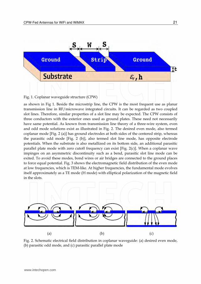
Fig. 1. Coplanar waveguide structure (CPW)
as shown in Fig 1. Beside the microstrip line, the CPW is the most frequent use as planar
transmission line in RF/microwave integrated circuits. It can be regarded as two coupled
slot lines. Therefore, similar properties of a slot line may be expected. The CPW consists of
three conductors with the exterior ones used as ground plates. These need not necessarily
have same potential. As known from transmission line theory of a three-wire system, even
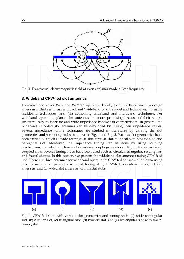
and odd mode solutions exist as illustrated in Fig. 2. The desired even mode, also termed
coplanar mode [Fig. 2 (a)] has ground electrodes at both sides of the centered strip, whereas
the parasitic odd mode [Fig. 2 (b)], also termed slot line mode, has opposite electrode
potentials. When the substrate is also metallized on its bottom side, an additional parasitic
parallel plate mode with zero cutoff frequency can exist [Fig. 2(c)]. When a coplanar wave
impinges on an asymmetric discontinuity such as a bend, parasitic slot line mode can be
exited. To avoid these modes, bond wires or air bridges are connected to the ground places
to force equal potential. Fig. 3 shows the electromagnetic field distribution of the even mode
at low frequencies, which is TEM-like. At higher frequencies, the fundamental mode evolves
itself approximately as a TE mode (H mode) with elliptical polarization of the magnetic field
in the slots.
(a) (b) (c)
Fig. 2. Schematic electrical field distribution in coplanar waveguide: (a) desired even mode, (b) parasitic odd mode, and (c) parasitic parallel plate mode
www.intechopen.com
Advanced Transmission Techniques in WiMAX
22
Fig. 3. Transversal electromagnetic field of even coplanar mode at low frequency
3. Wideband CPW-fed slot antennas
To realize and cover WiFi and WiMAX operation bands, there are three ways to design antennas including (i) using broadband/wideband or ultrawideband techniques, (ii) using multiband techniques, and (iii) combining wideband and multiband techniques. For wideband operation, planar slot antennas are more promising because of their simple structure, easy to fabricate and wide impedance bandwidth characteristics. In general, the wideband CPW-fed slot antennas can be developed by tuning their impedance values. Several impedance tuning techniques are studied in literatures by varying the slot geometries and/or tuning stubs as shown in Fig. 4 and Fig. 5. Various slot geometries have been carried out such as wide rectangular slot, circular slot, elliptical slot, bow-tie slot, and hexagonal slot. Moreover, the impedance tuning can be done by using coupling mechanisms, namely inductive and capacitive couplings as shown Fig. 5. For capacitively coupled slots, several tuning stubs have been used such as circular, triangular, rectangular, and fractal shapes. In this section, we present the wideband slot antennas using CPW feed line. There are three antennas for wideband operations: CPW-fed square slot antenna using loading metallic strips and a widened tuning stub, CPW-fed equilateral hexagonal slot antennas, and CPW-fed slot antennas with fractal stubs.
(a) (b) (c) (d) (e)
Fig. 4. CPW-fed slots with various slot geometries and tuning stubs (a) wide rectangular slot, (b) circular slot, (c) triangular slot, (d) bow-tie slot, and (e) rectangular slot with fractal tuning stub
www.intechopen.com
CPW-Fed Antennas for WiFi and WiMAX
23
(a) (b) (c) (d)
Fig. 5. CPW-fed slots with (a)-(b) inductive coupling and (c)–(d) capacitive coupling
3.1 CPW-fed square slot antenna using loading metallic strips and a widened tuning stub
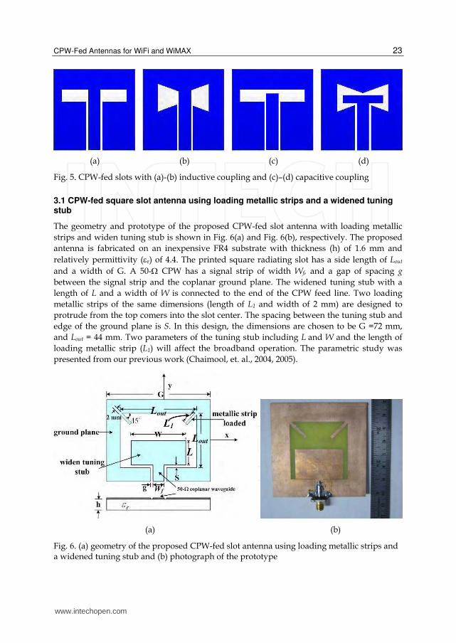
The geometry and prototype of the proposed CPW-fed slot antenna with loading metallic
strips and widen tuning stub is shown in Fig. 6(a) and Fig. 6(b), respectively. The proposed
antenna is fabricated on an inexpensive FR4 substrate with thickness (h) of 1.6 mm and
relatively permittivity (r) of 4.4. The printed square radiating slot has a side length of Lout
and a width of G. A 50- CPW has a signal strip of width Wf, and a gap of spacing g
between the signal strip and the coplanar ground plane. The widened tuning stub with a
length of L and a width of W is connected to the end of the CPW feed line. Two loading
metallic strips of the same dimensions (length of L1 and width of 2 mm) are designed to
protrude from the top comers into the slot center. The spacing between the tuning stub and
edge of the ground plane is S. In this design, the dimensions are chosen to be G =72 mm,
and Lout = 44 mm. Two parameters of the tuning stub including L and W and the length of
loading metallic strip (L1) will affect the broadband operation. The parametric study was
presented from our previous work (Chaimool, et. al., 2004, 2005).
(a) (b)
Fig. 6. (a) geometry of the proposed CPW-fed slot antenna using loading metallic strips and a widened tuning stub and (b) photograph of the prototype
www.intechopen.com
Advanced Transmission Techniques in WiMAX
24
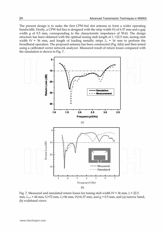
The present design is to make the first CPW-fed slot antenna to form a wider operating bandwidth. Firstly, a CPW-fed line is designed with the strip width Wf of 6.37 mm and a gap width g of 0.5 mm, corresponding to the characteristic impedance of 50-. The design structure has been obtained with the optimal tuning stub length of L =22.5 mm, tuning stub width W = 36 mm, and length of loading metallic strips L1 = 16 mm to perform the broadband operation. The proposed antenna has been constructed (Fig. 6(b)) and then tested using a calibrated vector network analyzer. Measured result of return losses compared with the simulation is shown in Fig. 7.
(a)
(b)
Fig. 7. Measured and simulated return losses for tuning stub width W = 36 mm, L = 22.5 mm, Lout = 44 mm, G=72 mm, L1=l6 mm, Wf=6.37 mm, and g = 0.5 mm, and (a) narrow band, (b) wideband views
www.intechopen.com
CPW-Fed Antennas for WiFi and WiMAX
25
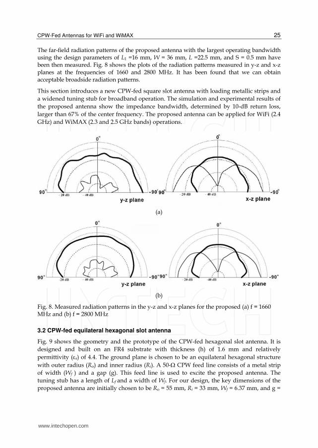
The far-field radiation patterns of the proposed antenna with the largest operating bandwidth using the design parameters of L1 =16 mm, W = 36 mm, L =22.5 mm, and S = 0.5 mm have been then measured. Fig. 8 shows the plots of the radiation patterns measured in y-z and x-z planes at the frequencies of 1660 and 2800 MHz. It has been found that we can obtain acceptable broadside radiation patterns.
This section introduces a new CPW-fed square slot antenna with loading metallic strips and
a widened tuning stub for broadband operation. The simulation and experimental results of
the proposed antenna show the impedance bandwidth, determined by 10-dB return loss,
larger than 67% of the center frequency. The proposed antenna can be applied for WiFi (2.4
GHz) and WiMAX (2.3 and 2.5 GHz bands) operations.
(a)
(b)
Fig. 8. Measured radiation patterns in the y-z and x-z planes for the proposed (a) f = 1660 MHz and (b) f = 2800 MHz
3.2 CPW-fed equilateral hexagonal slot antenna
Fig. 9 shows the geometry and the prototype of the CPW-fed hexagonal slot antenna. It is
designed and built on an FR4 substrate with thickness (h) of 1.6 mm and relatively
permittivity (r) of 4.4. The ground plane is chosen to be an equilateral hexagonal structure
with outer radius (Ro) and inner radius (Ri). A 50- CPW feed line consists of a metal strip
of width (Wf ) and a gap (g). This feed line is used to excite the proposed antenna. The
tuning stub has a length of Lf and a width of Wf. For our design, the key dimensions of the
proposed antenna are initially chosen to be Ro = 55 mm, Ri = 33 mm, Wf = 6.37 mm, and g =
www.intechopen.com
Advanced Transmission Techniques in WiMAX
26
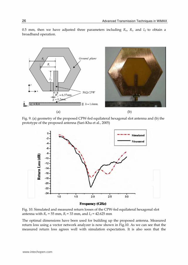
0.5 mm, then we have adjusted three parameters including Ro, Ri, and Lf to obtain a
broadband operation.
(a) (b)
Fig. 9. (a) geometry of the proposed CPW-fed equilateral hexagonal slot antenna and (b) the prototype of the proposed antenna (Sari-Kha et al., 2005)
Fig. 10. Simulated and measured return losses of the CPW-fed equilateral hexagonal slot antenna with Ro = 55 mm, Ri = 33 mm, and Lf = 42.625 mm
The optimal dimensions have been used for building up the proposed antenna. Measured return loss using a vector network analyzer is now shown in Fig.10. As we can see that the measured return loss agrees well with simulation expectation. It is also seen that the
www.intechopen.com
CPW-Fed Antennas for WiFi and WiMAX
27
proposed antenna has an operational frequency range from 1.657 to 2.956 GHz or bandwidth about 55% of the center frequency measured at higher 10 dB return loss.
This section presents design and implementation of the CPW-fed equilateral hexagonal slot antenna. The transmission line and ground-plane have been designed to be on the same plane with the antenna slot to be applicable for wideband operation. It is found that the proposed antenna is accessible to bandwidth about 55.39%, a very large bandwidth comparing with conventional microstrip antennas, which mostly provide 1-5 % bandwidth. The proposed antenna can be used for many wireless systems such as WiFi , WiMAX, GSM1800, GSM1900, and IMT-2000.
3.3 CPW-fed slot antennas with fractal stubs
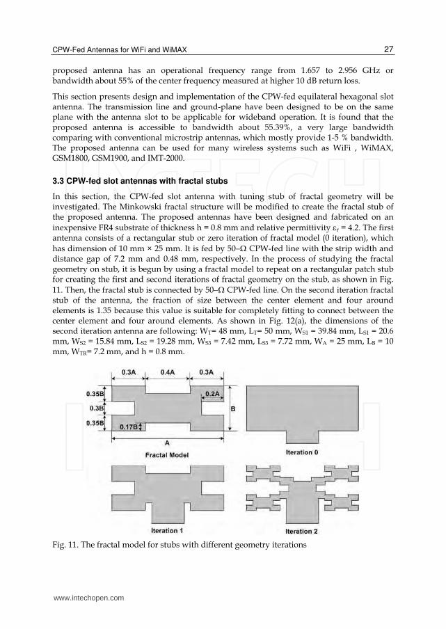
In this section, the CPW-fed slot antenna with tuning stub of fractal geometry will be investigated. The Minkowski fractal structure will be modified to create the fractal stub of the proposed antenna. The proposed antennas have been designed and fabricated on an
inexpensive FR4 substrate of thickness h = 0.8 mm and relative permittivity r = 4.2. The first antenna consists of a rectangular stub or zero iteration of fractal model (0 iteration), which
has dimension of 10 mm × 25 mm. It is fed by 50 CPW-fed line with the strip width and distance gap of 7.2 mm and 0.48 mm, respectively. In the process of studying the fractal geometry on stub, it is begun by using a fractal model to repeat on a rectangular patch stub for creating the first and second iterations of fractal geometry on the stub, as shown in Fig.
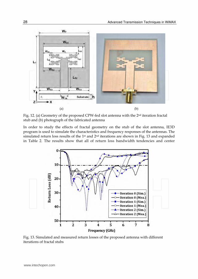
11. Then, the fractal stub is connected by 50 CPW-fed line. On the second iteration fractal stub of the antenna, the fraction of size between the center element and four around elements is 1.35 because this value is suitable for completely fitting to connect between the center element and four around elements. As shown in Fig. 12(a), the dimensions of the second iteration antenna are following: WT= 48 mm, LT= 50 mm, WS1 = 39.84 mm, LS1 = 20.6 mm, WS2 = 15.84 mm, LS2 = 19.28 mm, WS3 = 7.42 mm, LS3 = 7.72 mm, WA = 25 mm, LB = 10 mm, WTR= 7.2 mm, and h = 0.8 mm.
Fig. 11. The fractal model for stubs with different geometry iterations
www.intechopen.com
Advanced Transmission Techniques in WiMAX
28
(a) (b)
Fig. 12. (a) Geometry of the proposed CPW-fed slot antenna with the 2nd iteration fractal stub and (b) photograph of the fabricated antenna
In order to study the effects of fractal geometry on the stub of the slot antenna, IE3D program is used to simulate the characteristics and frequency responses of the antennas. The simulated return loss results of the 1st and 2nd iterations are shown in Fig. 13 and expanded in Table 2. The results show that all of return loss bandwidth tendencies and center
Fig. 13. Simulated and measured return losses of the proposed antenna with different iterations of fractal stubs
www.intechopen.com
CPW-Fed Antennas for WiFi and WiMAX
29
Antenna type
Center Frequency (GHz) Return Loss Bandwidth (RL ≥10 dB)
BW (GHz) BW (%)
Sim. Mea. Sim. Mea. Sim. Mea.
Iteration 0 4.3 4.5 1.6 - 7.1 1.7 – 7.1 123 121
Iteration 1 3.8 4.0 1.6 – 5.9 1.7 – 6.3 112 115
Iteration 2 2.7 2.8 1.6 – 3.8 1.7 – 4.0 78 82
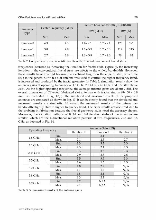
Table 2. Comparison of characteristic results with different iterations of fractal stubs.
frequencies decrease as increasing the iteration for fractal stub. Typically, the increasing iteration in the conventional fractal structure affects to the widely bandwidth. However, these results have inverted because the electrical length on the edge of stub, which the stub in the general CPW-fed slot antenna was used to control the higher frequency band, is increased and produced by the fractal geometry. In Table 3, simulation results show the antenna gains at operating frequency of 1.8 GHz, 2.1 GHz, 2.45 GHz, and 3.5 GHz above 3dBi. As the higher operating frequency, the average antenna gains are about 2 dBi. The overall dimension of CPW-fed fabricated slot antennas with fractal stub is 48× 50 × 0.8 mm3, as illustrated in Fig. 12(b). The simulated and measured results of the proposed antennas are compared as shown in Fig. 13. It can be clearly found that the simulated and measured results are similarity. However, the measured results of the return loss bandwidth slightly shift to higher frequency band. The error results are occurred due to the problem in fabrication because the fractal geometry stubs need the accuracy shapes. Moreover, the radiation patterns of 0, 1st and 2nd iteration stubs of the antennas are similar, which are the bidirectional radiation patterns at two frequencies, 2.45 and 3.5 GHz, as depicted in Fig. 14.
Operating Frequency Antenna Gain (dBi)
Iteration 0 Iteration 1 Iteration 2
1.8 GHz Sim. 3.1 3.1 3.1
Mea. 2.1 2.5 2.7
2.1 GHz Sim. 3.3 3.3 3.3
Mea. 2.3 2.1 2.3
2.45 GHz Sim. 3.3 3.3 3.3
Mea. 2.9 2.8 2.6
3.5 GHz Sim. 3.5 3.5 3.3
Mea. 1.6 1.5 1.3
5.2 GHz Sim. 1.8 2.2 N/A
Mea. 1.1 1.7 N/A
5.8 GHz Sim. 1.8 2.4 N/A
Mea. 1.3 2.2 N/A
6.9 GHz Sim. 2.2 N/A N/A
Mea. 2.1 N/A N/A
Table 3. Summarized results of the antenna gains
www.intechopen.com
Advanced Transmission Techniques in WiMAX
30
(a)
(b)
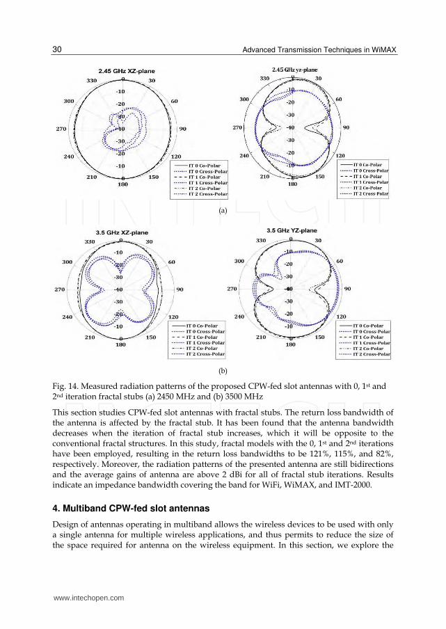
Fig. 14. Measured radiation patterns of the proposed CPW-fed slot antennas with 0, 1st and 2nd iteration fractal stubs (a) 2450 MHz and (b) 3500 MHz
This section studies CPW-fed slot antennas with fractal stubs. The return loss bandwidth of the antenna is affected by the fractal stub. It has been found that the antenna bandwidth decreases when the iteration of fractal stub increases, which it will be opposite to the conventional fractal structures. In this study, fractal models with the 0, 1st and 2nd iterations have been employed, resulting in the return loss bandwidths to be 121%, 115%, and 82%, respectively. Moreover, the radiation patterns of the presented antenna are still bidirections and the average gains of antenna are above 2 dBi for all of fractal stub iterations. Results indicate an impedance bandwidth covering the band for WiFi, WiMAX, and IMT-2000.
4. Multiband CPW-fed slot antennas
Design of antennas operating in multiband allows the wireless devices to be used with only a single antenna for multiple wireless applications, and thus permits to reduce the size of the space required for antenna on the wireless equipment. In this section, we explore the
www.intechopen.com
CPW-Fed Antennas for WiFi and WiMAX
31
possibility of covering some the standardized WiFi and WiMAX frequency bands while cling to the class of simply-structured and compact antennas.
4.1 Dual-band CPW-fed slot antennas using loading metallic strips and a widened tuning stub
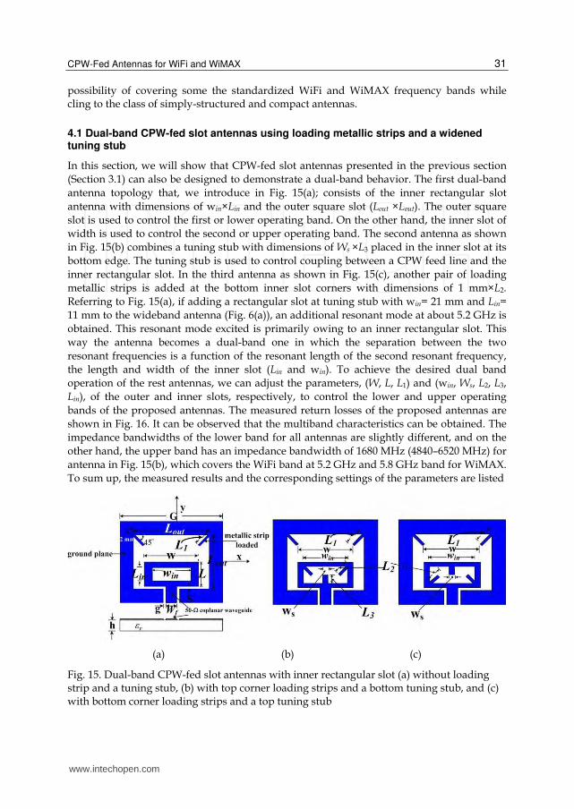
In this section, we will show that CPW-fed slot antennas presented in the previous section
(Section 3.1) can also be designed to demonstrate a dual-band behavior. The first dual-band
antenna topology that, we introduce in Fig. 15(a); consists of the inner rectangular slot
antenna with dimensions of win×Lin and the outer square slot (Lout ×Lout). The outer square
slot is used to control the first or lower operating band. On the other hand, the inner slot of
width is used to control the second or upper operating band. The second antenna as shown
in Fig. 15(b) combines a tuning stub with dimensions of Ws ×L3 placed in the inner slot at its
bottom edge. The tuning stub is used to control coupling between a CPW feed line and the
inner rectangular slot. In the third antenna as shown in Fig. 15(c), another pair of loading
metallic strips is added at the bottom inner slot corners with dimensions of 1 mm×L2.
Referring to Fig. 15(a), if adding a rectangular slot at tuning stub with win= 21 mm and Lin=
11 mm to the wideband antenna (Fig. 6(a)), an additional resonant mode at about 5.2 GHz is
obtained. This resonant mode excited is primarily owing to an inner rectangular slot. This
way the antenna becomes a dual-band one in which the separation between the two
resonant frequencies is a function of the resonant length of the second resonant frequency,
the length and width of the inner slot (Lin and win). To achieve the desired dual band
operation of the rest antennas, we can adjust the parameters, (W, L, L1) and (win, Ws, L2, L3,
Lin), of the outer and inner slots, respectively, to control the lower and upper operating
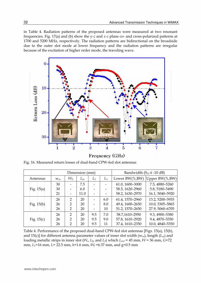
bands of the proposed antennas. The measured return losses of the proposed antennas are
shown in Fig. 16. It can be observed that the multiband characteristics can be obtained. The
impedance bandwidths of the lower band for all antennas are slightly different, and on the
other hand, the upper band has an impedance bandwidth of 1680 MHz (4840–6520 MHz) for
antenna in Fig. 15(b), which covers the WiFi band at 5.2 GHz and 5.8 GHz band for WiMAX.
To sum up, the measured results and the corresponding settings of the parameters are listed
(a) (b) (c)
Fig. 15. Dual-band CPW-fed slot antennas with inner rectangular slot (a) without loading strip and a tuning stub, (b) with top corner loading strips and a bottom tuning stub, and (c) with bottom corner loading strips and a top tuning stub
www.intechopen.com
Advanced Transmission Techniques in WiMAX
32
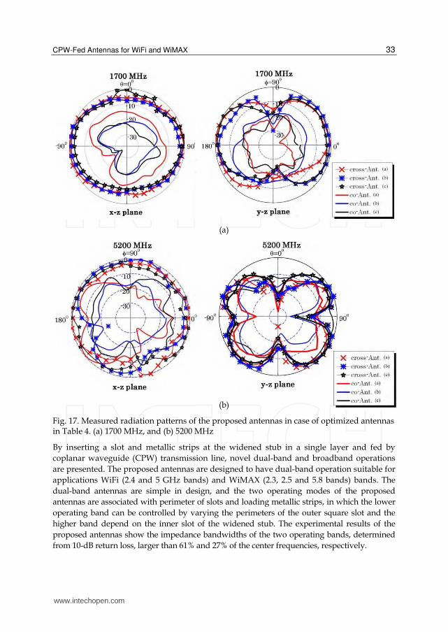
in Table 4. Radiation patterns of the proposed antennas were measured at two resonant frequencies. Fig. 17(a) and (b) show the y-z and x-z plane co- and cross-polarized patterns at 1700 and 5200 MHz, respectively. The radiation patterns are bidirectional on the broadside due to the outer slot mode at lower frequency and the radiation patterns are irregular because of the excitation of higher order mode, the traveling wave.
Fig. 16. Measured return losses of dual-band CPW-fed slot antennas
Dimension (mm) Bandwidth (S11 ≤ -10 dB)
Antennas win WS Lin L2 L3 Lower BW(%,BW) Upper BW(%,BW)
Fig. 15(a) 30 30 21
- - -
7.5 6.0
11.0
- - -
- - -
61.0, 1600–3000 58.5, 1620–2960 58.2, 1630–2970
7.5, 4880–5260 5.8, 5180–5490 16.1, 5040–5920
Fig. 15(b) 26 26 26
2 2 2
20 20 20
- - -
6.0 8.0 10
61.4, 1570–2960 49.4, 1600–2650 51.2, 1570–2650
13.2, 5200–5935 10.0, 5305–5865 27.9, 5060–6705
Fig. 15(c) 26 26 26
2 2 2
20 20 20
9.5 9.5 9.5
7.0 9.0 11
58.7,1610–2950 57.8, 1610–2920 37.4, 1610–2350
9.3, 4900–5380 9.4, 4870–5350 10.0, 4840–5350
Table 4. Performance of the proposed dual-band CPW-fed slot antennas [Figs. 15(a), 15(b), and 15(c)] for different antenna parameter values of inner slot width (win), length (Lin) and loading metallic strips in inner slot (Ws, L2, and L3) which Lout = 45 mm, W = 36 mm, G=72 mm, L1=16 mm, L= 22.5 mm, h=1.6 mm, Wf =6.37 mm, and g=0.5 mm
www.intechopen.com
CPW-Fed Antennas for WiFi and WiMAX
33
(a)
(b)
Fig. 17. Measured radiation patterns of the proposed antennas in case of optimized antennas in Table 4. (a) 1700 MHz, and (b) 5200 MHz
By inserting a slot and metallic strips at the widened stub in a single layer and fed by
coplanar waveguide (CPW) transmission line, novel dual-band and broadband operations
are presented. The proposed antennas are designed to have dual-band operation suitable for
applications WiFi (2.4 and 5 GHz bands) and WiMAX (2.3, 2.5 and 5.8 bands) bands. The
dual-band antennas are simple in design, and the two operating modes of the proposed
antennas are associated with perimeter of slots and loading metallic strips, in which the lower
operating band can be controlled by varying the perimeters of the outer square slot and the
higher band depend on the inner slot of the widened stub. The experimental results of the
proposed antennas show the impedance bandwidths of the two operating bands, determined
from 10-dB return loss, larger than 61% and 27% of the center frequencies, respectively.
www.intechopen.com
Advanced Transmission Techniques in WiMAX
34
4.2 CPW-fed mirrored-L monopole antenna with distinct triple bands
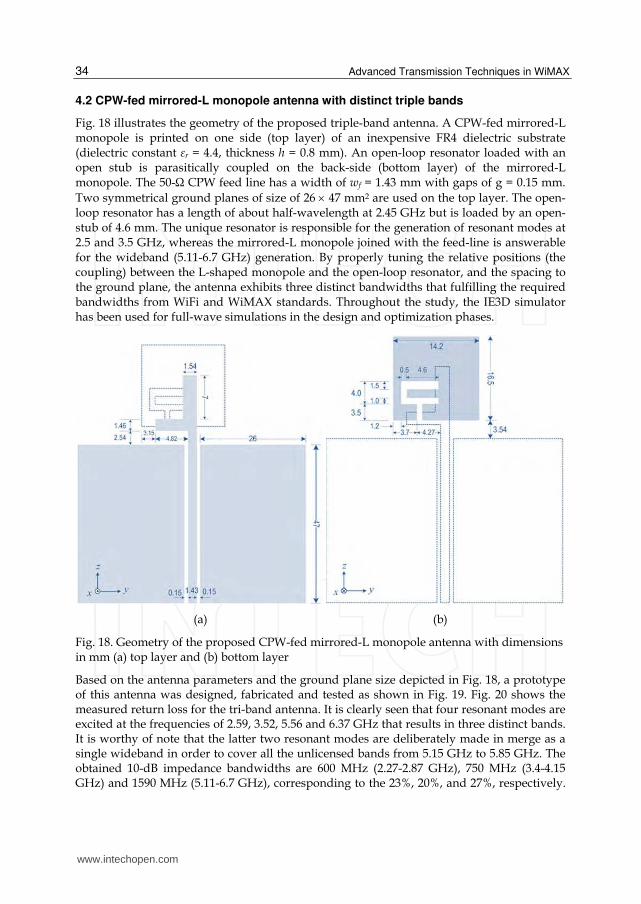
Fig. 18 illustrates the geometry of the proposed triple-band antenna. A CPW-fed mirrored-L monopole is printed on one side (top layer) of an inexpensive FR4 dielectric substrate (dielectric constant εr = 4.4, thickness h = 0.8 mm). An open-loop resonator loaded with an open stub is parasitically coupled on the back-side (bottom layer) of the mirrored-L monopole. The 50-Ω CPW feed line has a width of wf = 1.43 mm with gaps of g = 0.15 mm.
Two symmetrical ground planes of size of 26 47 mm2 are used on the top layer. The open-loop resonator has a length of about half-wavelength at 2.45 GHz but is loaded by an open-stub of 4.6 mm. The unique resonator is responsible for the generation of resonant modes at 2.5 and 3.5 GHz, whereas the mirrored-L monopole joined with the feed-line is answerable for the wideband (5.11-6.7 GHz) generation. By properly tuning the relative positions (the coupling) between the L-shaped monopole and the open-loop resonator, and the spacing to the ground plane, the antenna exhibits three distinct bandwidths that fulfilling the required bandwidths from WiFi and WiMAX standards. Throughout the study, the IE3D simulator has been used for full-wave simulations in the design and optimization phases.
(a) (b)
Fig. 18. Geometry of the proposed CPW-fed mirrored-L monopole antenna with dimensions in mm (a) top layer and (b) bottom layer
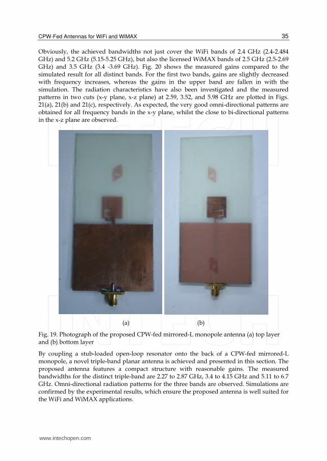
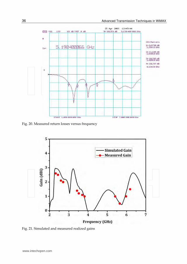
Based on the antenna parameters and the ground plane size depicted in Fig. 18, a prototype of this antenna was designed, fabricated and tested as shown in Fig. 19. Fig. 20 shows the measured return loss for the tri-band antenna. It is clearly seen that four resonant modes are excited at the frequencies of 2.59, 3.52, 5.56 and 6.37 GHz that results in three distinct bands. It is worthy of note that the latter two resonant modes are deliberately made in merge as a single wideband in order to cover all the unlicensed bands from 5.15 GHz to 5.85 GHz. The obtained 10-dB impedance bandwidths are 600 MHz (2.27-2.87 GHz), 750 MHz (3.4-4.15 GHz) and 1590 MHz (5.11-6.7 GHz), corresponding to the 23%, 20%, and 27%, respectively.
www.intechopen.com
CPW-Fed Antennas for WiFi and WiMAX
35
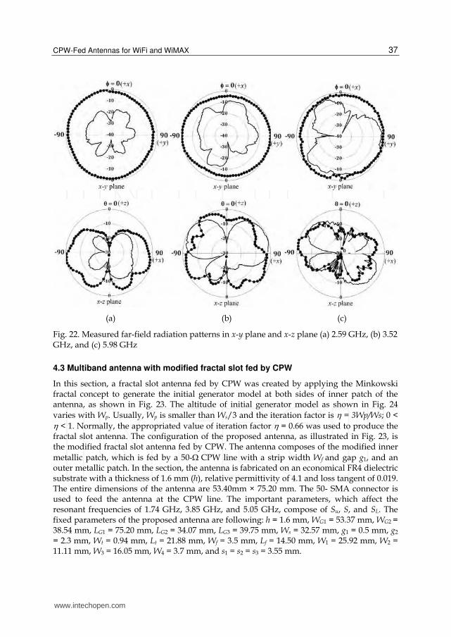
Obviously, the achieved bandwidths not just cover the WiFi bands of 2.4 GHz (2.4-2.484 GHz) and 5.2 GHz (5.15-5.25 GHz), but also the licensed WiMAX bands of 2.5 GHz (2.5-2.69 GHz) and 3.5 GHz (3.4 -3.69 GHz). Fig. 20 shows the measured gains compared to the simulated result for all distinct bands. For the first two bands, gains are slightly decreased with frequency increases, whereas the gains in the upper band are fallen in with the simulation. The radiation characteristics have also been investigated and the measured patterns in two cuts (x-y plane, x-z plane) at 2.59, 3.52, and 5.98 GHz are plotted in Figs. 21(a), 21(b) and 21(c), respectively. As expected, the very good omni-directional patterns are obtained for all frequency bands in the x-y plane, whilst the close to bi-directional patterns in the x-z plane are observed.
(a) (b)
Fig. 19. Photograph of the proposed CPW-fed mirrored-L monopole antenna (a) top layer and (b) bottom layer
By coupling a stub-loaded open-loop resonator onto the back of a CPW-fed mirrored-L monopole, a novel triple-band planar antenna is achieved and presented in this section. The proposed antenna features a compact structure with reasonable gains. The measured bandwidths for the distinct triple-band are 2.27 to 2.87 GHz, 3.4 to 4.15 GHz and 5.11 to 6.7 GHz. Omni-directional radiation patterns for the three bands are observed. Simulations are confirmed by the experimental results, which ensure the proposed antenna is well suited for the WiFi and WiMAX applications.
www.intechopen.com
Advanced Transmission Techniques in WiMAX
36
Fig. 20. Measured return losses versus frequency
Fig. 21. Simulated and measured realized gains
www.intechopen.com
CPW-Fed Antennas for WiFi and WiMAX
37
(a) (b) (c)
Fig. 22. Measured far-field radiation patterns in x-y plane and x-z plane (a) 2.59 GHz, (b) 3.52 GHz, and (c) 5.98 GHz
4.3 Multiband antenna with modified fractal slot fed by CPW
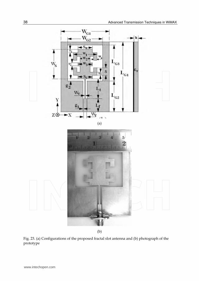
In this section, a fractal slot antenna fed by CPW was created by applying the Minkowski fractal concept to generate the initial generator model at both sides of inner patch of the antenna, as shown in Fig. 23. The altitude of initial generator model as shown in Fig. 24
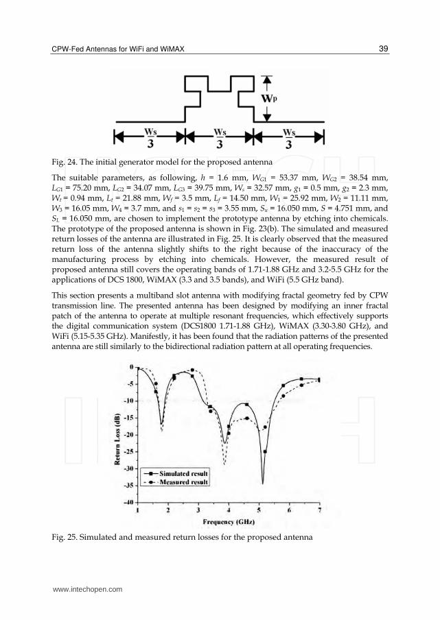
varies with Wp. Usually, Wp is smaller than Ws/3 and the iteration factor is = 3Wp/Ws; 0 < < 1. Normally, the appropriated value of iteration factor = 0.66 was used to produce the fractal slot antenna. The configuration of the proposed antenna, as illustrated in Fig. 23, is the modified fractal slot antenna fed by CPW. The antenna composes of the modified inner
metallic patch, which is fed by a 50-CPW line with a strip width Wf and gap g1, and an outer metallic patch. In the section, the antenna is fabricated on an economical FR4 dielectric substrate with a thickness of 1.6 mm (h), relative permittivity of 4.1 and loss tangent of 0.019. The entire dimensions of the antenna are 53.40mm × 75.20 mm. The 50- SMA connector is used to feed the antenna at the CPW line. The important parameters, which affect the resonant frequencies of 1.74 GHz, 3.85 GHz, and 5.05 GHz, compose of Su, S, and SL. The fixed parameters of the proposed antenna are following: h = 1.6 mm, WG1 = 53.37 mm, WG2 = 38.54 mm, LG1 = 75.20 mm, LG2 = 34.07 mm, LG3 = 39.75 mm, Ws = 32.57 mm, g1 = 0.5 mm, g2 = 2.3 mm, Wt = 0.94 mm, Lt = 21.88 mm, Wf = 3.5 mm, Lf = 14.50 mm, W1 = 25.92 mm, W2 = 11.11 mm, W3 = 16.05 mm, W4 = 3.7 mm, and s1 = s2 = s3 = 3.55 mm.
www.intechopen.com
Advanced Transmission Techniques in WiMAX
38
(a)
(b)
Fig. 23. (a) Configurations of the proposed fractal slot antenna and (b) photograph of the prototype
www.intechopen.com
CPW-Fed Antennas for WiFi and WiMAX
39
Fig. 24. The initial generator model for the proposed antenna
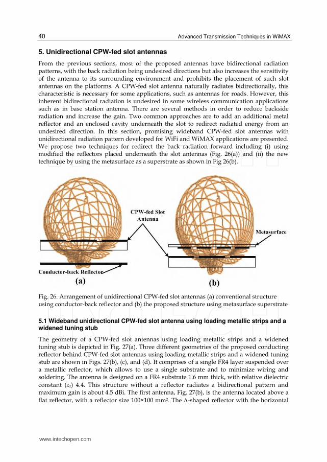
The suitable parameters, as following, h = 1.6 mm, WG1 = 53.37 mm, WG2 = 38.54 mm, LG1 = 75.20 mm, LG2 = 34.07 mm, LG3 = 39.75 mm, Ws = 32.57 mm, g1 = 0.5 mm, g2 = 2.3 mm, Wt = 0.94 mm, Lt = 21.88 mm, Wf = 3.5 mm, Lf = 14.50 mm, W1 = 25.92 mm, W2 = 11.11 mm, W3 = 16.05 mm, W4 = 3.7 mm, and s1 = s2 = s3 = 3.55 mm, Su = 16.050 mm, S = 4.751 mm, and SL = 16.050 mm, are chosen to implement the prototype antenna by etching into chemicals. The prototype of the proposed antenna is shown in Fig. 23(b). The simulated and measured return losses of the antenna are illustrated in Fig. 25. It is clearly observed that the measured return loss of the antenna slightly shifts to the right because of the inaccuracy of the manufacturing process by etching into chemicals. However, the measured result of proposed antenna still covers the operating bands of 1.71-1.88 GHz and 3.2-5.5 GHz for the applications of DCS 1800, WiMAX (3.3 and 3.5 bands), and WiFi (5.5 GHz band).
This section presents a multiband slot antenna with modifying fractal geometry fed by CPW transmission line. The presented antenna has been designed by modifying an inner fractal patch of the antenna to operate at multiple resonant frequencies, which effectively supports the digital communication system (DCS1800 1.71-1.88 GHz), WiMAX (3.30-3.80 GHz), and WiFi (5.15-5.35 GHz). Manifestly, it has been found that the radiation patterns of the presented antenna are still similarly to the bidirectional radiation pattern at all operating frequencies.
Fig. 25. Simulated and measured return losses for the proposed antenna
www.intechopen.com
Advanced Transmission Techniques in WiMAX
40
5. Unidirectional CPW-fed slot antennas
From the previous sections, most of the proposed antennas have bidirectional radiation patterns, with the back radiation being undesired directions but also increases the sensitivity of the antenna to its surrounding environment and prohibits the placement of such slot antennas on the platforms. A CPW-fed slot antenna naturally radiates bidirectionally, this characteristic is necessary for some applications, such as antennas for roads. However, this inherent bidirectional radiation is undesired in some wireless communication applications such as in base station antenna. There are several methods in order to reduce backside radiation and increase the gain. Two common approaches are to add an additional metal reflector and an enclosed cavity underneath the slot to redirect radiated energy from an undesired direction. In this section, promising wideband CPW-fed slot antennas with unidirectional radiation pattern developed for WiFi and WiMAX applications are presented. We propose two techniques for redirect the back radiation forward including (i) using modified the reflectors placed underneath the slot antennas (Fig. 26(a)) and (ii) the new technique by using the metasurface as a superstrate as shown in Fig 26(b).
Fig. 26. Arrangement of unidirectional CPW-fed slot antennas (a) conventional structure using conductor-back reflector and (b) the proposed structure using metasurface superstrate
5.1 Wideband unidirectional CPW-fed slot antenna using loading metallic strips and a widened tuning stub
The geometry of a CPW-fed slot antennas using loading metallic strips and a widened tuning stub is depicted in Fig. 27(a). Three different geometries of the proposed conducting reflector behind CPW-fed slot antennas using loading metallic strips and a widened tuning stub are shown in Figs. 27(b), (c), and (d). It comprises of a single FR4 layer suspended over a metallic reflector, which allows to use a single substrate and to minimize wiring and soldering. The antenna is designed on a FR4 substrate 1.6 mm thick, with relative dielectric
constant (r) 4.4. This structure without a reflector radiates a bidirectional pattern and maximum gain is about 4.5 dBi. The first antenna, Fig. 27(b), is the antenna located above a
flat reflector, with a reflector size 100×100 mm2. The -shaped reflector with the horizontal
www.intechopen.com
CPW-Fed Antennas for WiFi and WiMAX
41
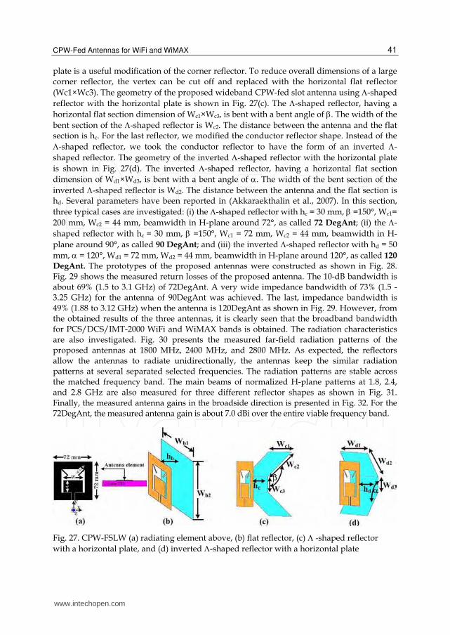
plate is a useful modification of the corner reflector. To reduce overall dimensions of a large corner reflector, the vertex can be cut off and replaced with the horizontal flat reflector
(Wc1×Wc3). The geometry of the proposed wideband CPW-fed slot antenna using -shaped
reflector with the horizontal plate is shown in Fig. 27(c). The -shaped reflector, having a
horizontal flat section dimension of Wc1×Wc3, is bent with a bent angle of . The width of the
bent section of the -shaped reflector is Wc2. The distance between the antenna and the flat section is hc. For the last reflector, we modified the conductor reflector shape. Instead of the
-shaped reflector, we took the conductor reflector to have the form of an inverted -
shaped reflector. The geometry of the inverted -shaped reflector with the horizontal plate
is shown in Fig. 27(d). The inverted -shaped reflector, having a horizontal flat section
dimension of Wd1×Wd3, is bent with a bent angle of . The width of the bent section of the
inverted -shaped reflector is Wd2. The distance between the antenna and the flat section is hd. Several parameters have been reported in (Akkaraekthalin et al., 2007). In this section,
three typical cases are investigated: (i) the -shaped reflector with hc = 30 mm, =150°, Wc1=
200 mm, Wc2 = 44 mm, beamwidth in H-plane around 72°, as called 72 DegAnt; (ii) the -
shaped reflector with hc = 30 mm, =150°, Wc1 = 72 mm, Wc2 = 44 mm, beamwidth in H-
plane around 90°, as called 90 DegAnt; and (iii) the inverted -shaped reflector with hd = 50
mm, = 120°, Wd1 = 72 mm, Wd2 = 44 mm, beamwidth in H-plane around 120°, as called 120
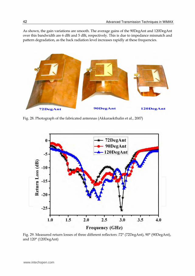
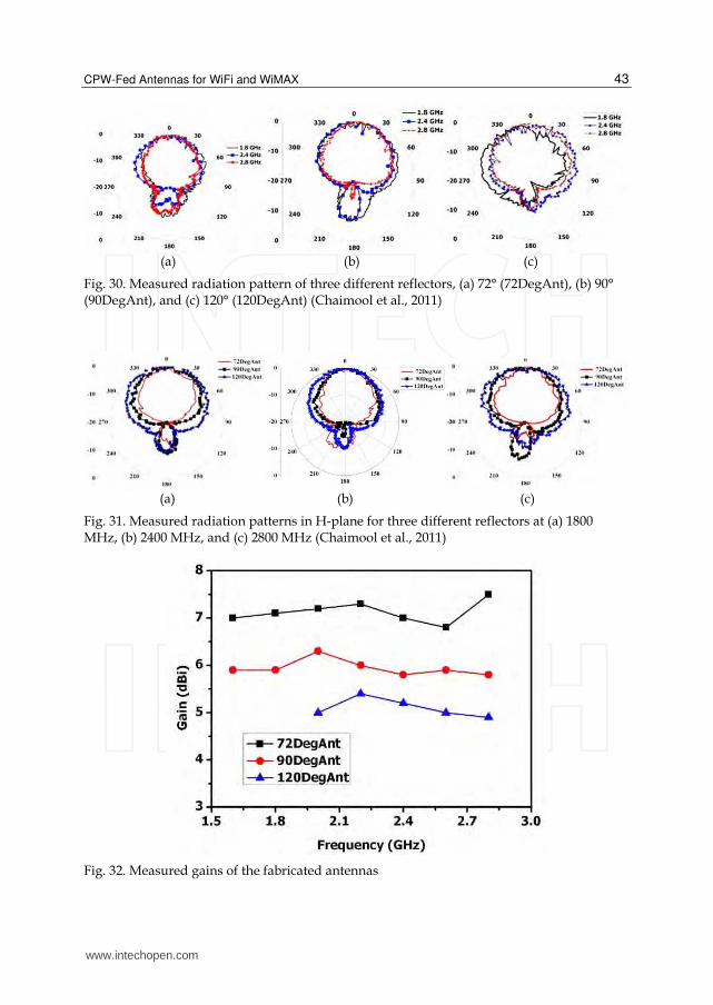
DegAnt. The prototypes of the proposed antennas were constructed as shown in Fig. 28. Fig. 29 shows the measured return losses of the proposed antenna. The 10-dB bandwidth is about 69% (1.5 to 3.1 GHz) of 72DegAnt. A very wide impedance bandwidth of 73% (1.5 - 3.25 GHz) for the antenna of 90DegAnt was achieved. The last, impedance bandwidth is 49% (1.88 to 3.12 GHz) when the antenna is 120DegAnt as shown in Fig. 29. However, from the obtained results of the three antennas, it is clearly seen that the broadband bandwidth for PCS/DCS/IMT-2000 WiFi and WiMAX bands is obtained. The radiation characteristics are also investigated. Fig. 30 presents the measured far-field radiation patterns of the proposed antennas at 1800 MHz, 2400 MHz, and 2800 MHz. As expected, the reflectors allow the antennas to radiate unidirectionally, the antennas keep the similar radiation patterns at several separated selected frequencies. The radiation patterns are stable across the matched frequency band. The main beams of normalized H-plane patterns at 1.8, 2.4, and 2.8 GHz are also measured for three different reflector shapes as shown in Fig. 31. Finally, the measured antenna gains in the broadside direction is presented in Fig. 32. For the 72DegAnt, the measured antenna gain is about 7.0 dBi over the entire viable frequency band.
Fig. 27. CPW-FSLW (a) radiating element above, (b) flat reflector, (c) -shaped reflector
with a horizontal plate, and (d) inverted -shaped reflector with a horizontal plate
www.intechopen.com
Advanced Transmission Techniques in WiMAX
42
As shown, the gain variations are smooth. The average gains of the 90DegAnt and 120DegAnt over this bandwidth are 6 dBi and 5 dBi, respectively. This is due to impedance mismatch and pattern degradation, as the back radiation level increases rapidly at these frequencies.
Fig. 28. Photograph of the fabricated antennas (Akkaraekthalin et al., 2007)
Fig. 29. Measured return losses of three different reflectors :72° (72DegAnt), 90° (90DegAnt), and 120° (120DegAnt)
www.intechopen.com
CPW-Fed Antennas for WiFi and WiMAX
43
(a) (b) (c)
Fig. 30. Measured radiation pattern of three different reflectors, (a) 72° (72DegAnt), (b) 90° (90DegAnt), and (c) 120° (120DegAnt) (Chaimool et al., 2011)
(a) (b) (c)
Fig. 31. Measured radiation patterns in H-plane for three different reflectors at (a) 1800 MHz, (b) 2400 MHz, and (c) 2800 MHz (Chaimool et al., 2011)
Fig. 32. Measured gains of the fabricated antennas
www.intechopen.com
Advanced Transmission Techniques in WiMAX
44
5.2 Unidirectional CPW-fed slot antenna using metasurface
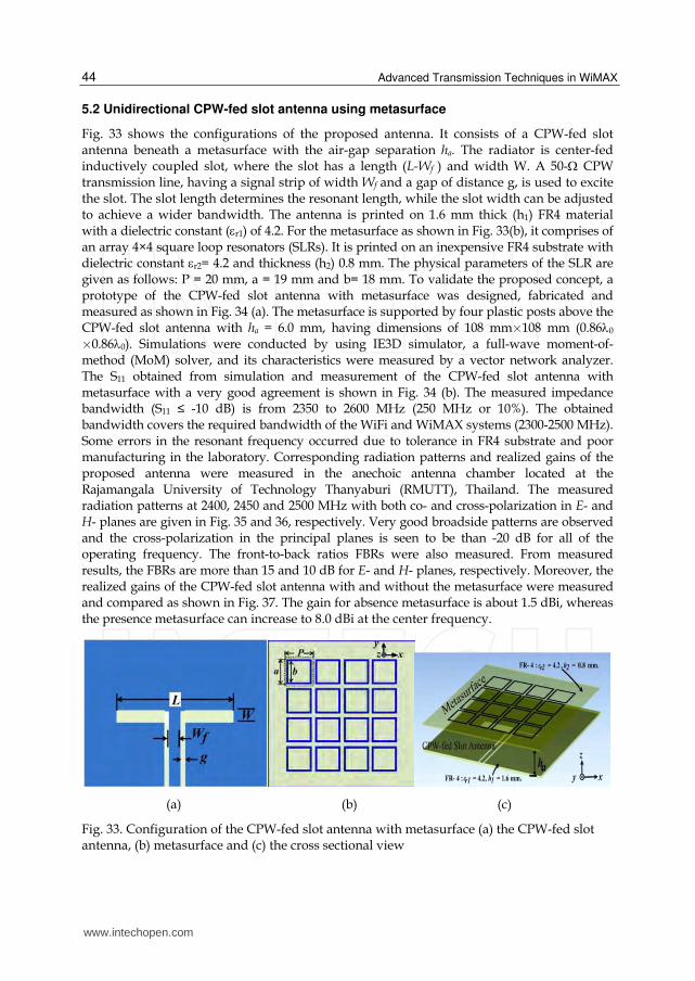
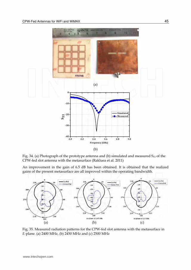
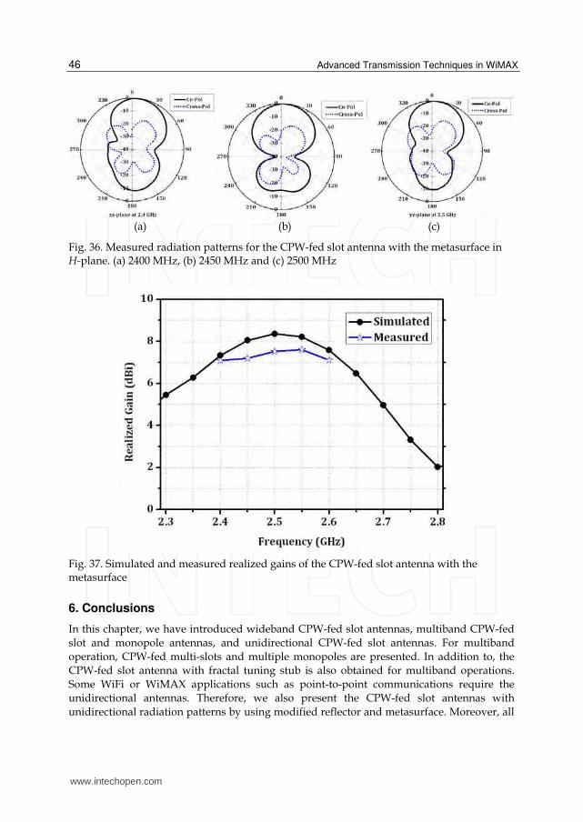
Fig. 33 shows the configurations of the proposed antenna. It consists of a CPW-fed slot antenna beneath a metasurface with the air-gap separation ha. The radiator is center-fed inductively coupled slot, where the slot has a length (L-Wf ) and width W. A 50- CPW transmission line, having a signal strip of width Wf and a gap of distance g, is used to excite the slot. The slot length determines the resonant length, while the slot width can be adjusted to achieve a wider bandwidth. The antenna is printed on 1.6 mm thick (h1) FR4 material with a dielectric constant (r1) of 4.2. For the metasurface as shown in Fig. 33(b), it comprises of an array 4×4 square loop resonators (SLRs). It is printed on an inexpensive FR4 substrate with dielectric constant r2= 4.2 and thickness (h2) 0.8 mm. The physical parameters of the SLR are given as follows: P = 20 mm, a = 19 mm and b= 18 mm. To validate the proposed concept, a prototype of the CPW-fed slot antenna with metasurface was designed, fabricated and measured as shown in Fig. 34 (a). The metasurface is supported by four plastic posts above the CPW-fed slot antenna with ha = 6.0 mm, having dimensions of 108 mm´108 mm (0.860 ´0.860). Simulations were conducted by using IE3D simulator, a full-wave moment-of- method (MoM) solver, and its characteristics were measured by a vector network analyzer. The S11 obtained from simulation and measurement of the CPW-fed slot antenna with metasurface with a very good agreement is shown in Fig. 34 (b). The measured impedance bandwidth (S11 ≤ -10 dB) is from 2350 to 2600 MHz (250 MHz or 10%). The obtained bandwidth covers the required bandwidth of the WiFi and WiMAX systems (2300-2500 MHz). Some errors in the resonant frequency occurred due to tolerance in FR4 substrate and poor manufacturing in the laboratory. Corresponding radiation patterns and realized gains of the proposed antenna were measured in the anechoic antenna chamber located at the Rajamangala University of Technology Thanyaburi (RMUTT), Thailand. The measured radiation patterns at 2400, 2450 and 2500 MHz with both co- and cross-polarization in E- and H- planes are given in Fig. 35 and 36, respectively. Very good broadside patterns are observed and the cross-polarization in the principal planes is seen to be than -20 dB for all of the operating frequency. The front-to-back ratios FBRs were also measured. From measured results, the FBRs are more than 15 and 10 dB for E- and H- planes, respectively. Moreover, the realized gains of the CPW-fed slot antenna with and without the metasurface were measured and compared as shown in Fig. 37. The gain for absence metasurface is about 1.5 dBi, whereas the presence metasurface can increase to 8.0 dBi at the center frequency.
(a) (b) (c)
Fig. 33. Configuration of the CPW-fed slot antenna with metasurface (a) the CPW-fed slot antenna, (b) metasurface and (c) the cross sectional view
www.intechopen.com
CPW-Fed Antennas for WiFi and WiMAX
45
(a)
(b)
Fig. 34. (a) Photograph of the prototype antenna and (b) simulated and measured S11 of the CPW-fed slot antenna with the metasurface (Rakluea et al. 2011)
An improvement in the gain of 6.5 dB has been obtained. It is obtained that the realized gains of the present metasurface are all improved within the operating bandwidth.
(a) (b) (c)
Fig. 35. Measured radiation patterns for the CPW-fed slot antenna with the metasurface in E-plane. (a) 2400 MHz, (b) 2450 MHz and (c) 2500 MHz
www.intechopen.com
Advanced Transmission Techniques in WiMAX
46
(a) (b) (c)
Fig. 36. Measured radiation patterns for the CPW-fed slot antenna with the metasurface in H-plane. (a) 2400 MHz, (b) 2450 MHz and (c) 2500 MHz
Fig. 37. Simulated and measured realized gains of the CPW-fed slot antenna with the metasurface
6. Conclusions
In this chapter, we have introduced wideband CPW-fed slot antennas, multiband CPW-fed
slot and monopole antennas, and unidirectional CPW-fed slot antennas. For multiband
operation, CPW-fed multi-slots and multiple monopoles are presented. In addition to, the
CPW-fed slot antenna with fractal tuning stub is also obtained for multiband operations.
Some WiFi or WiMAX applications such as point-to-point communications require the
unidirectional antennas. Therefore, we also present the CPW-fed slot antennas with
unidirectional radiation patterns by using modified reflector and metasurface. Moreover, all
www.intechopen.com
CPW-Fed Antennas for WiFi and WiMAX
47
of antennas are fabricated on an inexpensive FR4, therefore, they are suitable for mass
productions. This suggests that the proposed antennas are well suited for WiFi as well as
WiMAX portable units and base stations.
7. References
Akkaraekthalin, P.; Chaimool, S.; Krairiksk, M. (September 2007) Wideband uni-directional
CPW-fed slot antennas using loading metallic strips and a widened tuning stub on
modified-shape reflectors, IEICE Trans Communications, vol. E90-B, no.9, pp.2246-
2255, ISSN 0916-8516.
Chaimool, S.; Akkaraekthalin P.; Krairiksh, M.(May 2011). Wideband Constant beamwidth
coplanar waveguide-fed slot antennas using metallic strip loading and a wideband
tuning stub with shaped reflector, International Journal of RF and Microwave
Computer – Aided Engineering, vol. 21, no 3, pp. 263-271, ISSN 1099-047X
Chaimool, S.; Akkaraekthalin, P.; Vivek, V. (December 2005). Dual-band CPW-fed slot
antennas using loading metallic strips and a widened tuning stub, IEICE
Transactions on Electronics, vol. E88-C, no.12, pp.2258-2265, ISSN 0916-8524.
Chaimool, S.; Chung, K. L. (2009). CPW-fed mirrored-L monopole antenna with distinct
triple bands for WiFi and WiMAX applications, Electronics Letters, vol. 45, no. 18,
pp. 928-929, ISSN 0916-8524.
Chaimool, S.; Jirasakulporn, P.; Akkaraekthalin, P. (2008) A new compact dual-band CPW-
fed slot antenna with inverted-F tuning stub, Proceedings of ISAP-2008 International
Symposium on Antennas and Propagation, Taipei, Taiwan, pp. 1190-1193, ISBN: 978-4-
88552-223-9
Chaimool, S.; Kerdsumang, S.; Akkraeakthalin, P.; Vivek, V.(2004) A broadband CPW-fed
square slot antenna using loading metallic strips and a widened tuning stub,
Proceedings of ISCIT 2004 International Symposium on Communications and Information
Technologies, Sapporo, Japan, vol. 2, pp. 730-733, ISBN: 0-7803-8593-4
Hongnara, T.; Mahatthanajatuphat C.; Akkaraekthalin, P. (2011). Study of CPW-fed slot
antennas with fractal stubs, Proceedings of ECTI-CON2011 8th International Conference
of Electrical Engineering/Electronics, Computer, Telecommunications and Information
Technology, pp. 188-191, Khonkean, Thailand, May 17-19, 2011, ISBN: 978-1-4577-
0425-3
Jirasakulporn, P. (December 2008). Multiband CPW-fed slot antenna with L-slot bowtie
tuning stub, World Academy of Science, Engineering and Technology, vol. 48, pp.72-76,
ISSN 2010-376X
Mahatthanajatuphat, C. ; Akkaraekthalin, P.; Saleekaw, S.; Krairiksh, M. (2009). A
bidirectional multiband antenna with modified fractal slot fed by CPW, Progress In
Electromagnetics Research, vol. 95, pp. 59-72, ISSN 1070-4698
Moeikham, P.; Mahatthanajatuphat, C.; Akkaraekthalin, P.(2011). A compact ultrawideband
monopole antenna with tapered CPW feed and slot stubs, Proceedings of ECTI-
CON2011 8th International Conference of Electrical Engineering/Electronics, Computer,
Telecommunications and Information Technology, pp. 180-183, Khonkean, Thailand,
May 17-19, 2011, ISBN: 978-1-4577-0425-3
www.intechopen.com

Advanced Transmission Techniques in WiMAX
48
Rakluea, C.; Chaimool, S.; Akkaraekthalin, P. (2011). Unidirectional CPW-fed slot antenna
using metasurface, Proceedings of ECTI-CON2011 8th International Conference
of Electrical Engineering/Electronics, Computer, Telecommunications and Information
Technology, pp. 184-187, Khonkean, Thailand, May 17-19, 2011, ISBN: 978-1-4577-
0425-3
Sari-Kha, K.; Vivek, V.; Akkaraekthalin, P. (2006) A broadband CPW-fed equilateral
hexagonal slot antenna, Proceedings of ISCIT 2006 International Symposium on
Communications and Information Technologies, Bangkok, Thailand, pp. 783-786,
October 18-20, 2006, ISBN 0-7803-9741-X.
www.intechopen.com

Advanced Transmission Techniques in WiMAXEdited by Dr. Roberto Hincapie
ISBN 978-953-307-965-3Hard cover, 336 pagesPublisher InTechPublished online 18, January, 2012Published in print edition January, 2012
InTech EuropeUniversity Campus STeP Ri Slavka Krautzeka 83/A 51000 Rijeka, Croatia Phone: +385 (51) 770 447 Fax: +385 (51) 686 166www.intechopen.com
InTech ChinaUnit 405, Office Block, Hotel Equatorial Shanghai No.65, Yan An Road (West), Shanghai, 200040, China
Phone: +86-21-62489820 Fax: +86-21-62489821
This book has been prepared to present the state of the art on WiMAX Technology. The focus of the book isthe physical layer, and it collects the contributions of many important researchers around the world. So manydifferent works on WiMAX show the great worldwide importance of WiMAX as a wireless broadband accesstechnology. This book is intended for readers interested in the transmission process under WiMAX. Allchapters include both theoretical and technical information, which provides an in-depth review of the mostrecent advances in the field, for engineers and researchers, and other readers interested in WiMAX.
How to referenceIn order to correctly reference this scholarly work, feel free to copy and paste the following:
Sarawuth Chaimool and Prayoot Akkaraekthalin (2012). CPW-Fed Antennas for WiFi and WiMAX, AdvancedTransmission Techniques in WiMAX, Dr. Roberto Hincapie (Ed.), ISBN: 978-953-307-965-3, InTech, Availablefrom: http://www.intechopen.com/books/advanced-transmission-techniques-in-wimax/cpw-fed-antennas-for-wifi-and-wimax