Embed Size (px)
Citation preview
8V LI-ION CORDLESS DRIVER
054-1247-0
Owner’s Manual
PRODUCT SPECIFICATIONS
Rotation: Clockwise or counter clockwise
Variable speed: 0–400 RPM (no load)
Variable torque: 88 in/lb (maximum)
Torque clutch positions: 16 + drill mode
Hex drive: Quick release ¼" (6.35 mm)
Battery: Integral 8V Li-ion, 1.5 Ah (Maximum charged battery voltage, measured without load, is 8V with a nominal value of 7.2V)
Battery charger: 3–5 hour, Class 2
Charger input: 120 V AC, 60 Hz
Charger output: 9 V DC, 400 mA (maximum)
Weight: 1 lb 12 oz (0.79 kg)
Need Assistance? Call us on our toll free customer support line: 1-800-689-9928
Technical questions Replacement parts
Parts missing from package
Imported by Mastercraft Canada Toronto, Canada M4S 2B8
Maximum charged battery voltage, measured without load, is 8V with a nominal value of 7.2V
2
Product specifications ………….………………………………………………………………... 1 Table of contents …………………………………………………………………….................. 2 General safety warnings ………………………………………………………………………… 3–4 Eye, ear & lung protection ………………………………………………………………………. 3–4 Electrical safety …………………………………………………………………………………... 4 Power tool safety …………………………………………………………………….................. 5–6 General safety rules ……………………………………………………………………………... 5 Work area ………………………………………………………………….……………………... 5 Electrical safety …………………………………………………………………………………... 5 Personal safety …………………………………………………………………………………... 5–6 Power tool use and care .……………………………………………………………………….. 6 Battery tool use and care ……………………………………………………………………….. 6 Service ……………………………………………………………………………………………. 6 Specific safety rules ……………………………………………………………………………... 7 Battery & charger safety ………………………………………………………….……………... 8 Battery pack recycling …………………………………………………………………………… 8 Symbols …………………………………………………………………………………………… 9 Know your cordless driver ………………………………………………………………………. 10 Assembly and operating ………………………………………………………………………… 11–14 Charging the battery …………………………………………………………………………….. 11 LED worklight / battery charging indicator ……………………………………………………. 11 Installing screwdriver bits ………………………………………………………………………. 11–12 Forward/reverse switch …………………………………………………………………………. 12 Variable speed trigger switch …………………………………………………………………… 12 Adjusting the torque collar ………………………………………………………………………. 12–13 Preparing screw holes …………………………………………………………………………... 13 Driving screws ……………………………………………………………………………………. 14 Maintenance ……………………………………………………………………………………… 15 General maintenance ……………………………………………………………………………. 15 Lubrication ………………………………………………………………………………………... 15 Lithium-ion battery performance ……………………………………………………………….. 15 Lithium-ion battery maintenance ……………………………………………………………….. 15 Battery pack removal and preparation for recycling …………………………………………. 15 Exploded view ……………………………………………………………………………………. 16 Parts list …………………………………………………………………………………………… 17–18 Warranty ……………………………………………………………………….…………………. 19–20
TABLE OF CONTENTS
3
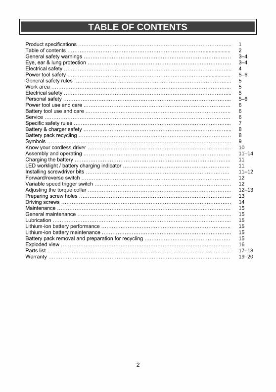
EYE, EAR & LUNG PROTECTION
This instruction manual includes the following:
General Safety Rules
Specific Safety Rules and Symbols
Functional Description
Assembly
Operation
Maintenance
Accessories
!
ALWAYS WEAR EYE PROTECTION THAT CONFORMS WITH CSA
REQUIREMENTS or ANSI SAFETY STANDARD Z87.1
FLYING DEBRIS can cause permanent eye damage. Prescription
eyeglasses ARE NOT a replacement for proper eye protection.
WARNING: Non-compliant eyewear can cause serious injury if
broken during the operation of a power tool.
WARNING: Use hearing protection, particularly during extended
periods of operation of the tool, or if the operation is noisy. !
GENERAL SAFETY WARNINGS
WARNING: Before using this tool or any of its accessories, read this manual and follow all Safety Rules and Operating Instructions. The important precautions, safeguards and instructions appearing in this manual are not meant to cover all possible situations. It must be understood that common
sense and caution are factors which cannot be built into the product.
!
SAVE THESE INSTRUCTIONS FOR REFERENCE
4
ELECTRICAL SAFETY
GENERAL SAFETY WARNINGS
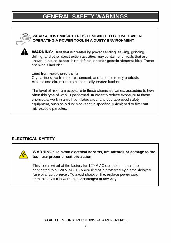
WEAR A DUST MASK THAT IS DESIGNED TO BE USED WHEN
OPERATING A POWER TOOL IN A DUSTY ENVIRONMENT.
WARNING: Dust that is created by power sanding, sawing, grinding,
drilling, and other construction activities may contain chemicals that are known to cause cancer, birth defects, or other genetic abnormalities. These chemicals include:
Lead from lead-based paints Crystalline silica from bricks, cement, and other masonry products Arsenic and chromium from chemically treated lumber
The level of risk from exposure to these chemicals varies, according to how
often this type of work is performed. In order to reduce exposure to these
chemicals, work in a well-ventilated area, and use approved safety
equipment, such as a dust mask that is specifically designed to filter out
microscopic particles.
!
WARNING: To avoid electrical hazards, fire hazards or damage to the
tool, use proper circuit protection.
This tool is wired at the factory for 120 V AC operation. It must be
connected to a 120 V AC, 15 A circuit that is protected by a time-delayed
fuse or circuit breaker. To avoid shock or fire, replace power cord
immediately if it is worn, cut or damaged in any way.
SAVE THESE INSTRUCTIONS FOR REFERENCE
5
WARNING: Read all safety warnings and instructions. Failure to follow the warnings and instructions may result in electric shock, fire and/or serious injury. Save all warnings and instructions for future reference. Work area safety Keep work area clean and well lit. Cluttered or dark areas invite accidents. Do not operate power tools in explosive atmospheres, such as in the presence of flammable liquids, gases or dust. Power tools create sparks which may ignite the dust or fumes. Keep children and bystanders away while operating a power tool. Distractions can cause you to lose control. Electrical safety Power tool plugs must match the outlet. Never modify the plug in any way. Do not use any adapter plugs with earthed (grounded) power tools. Unmodified plugs and matching outlets will reduce risk of electric shock.
Avoid body contact with earthed or grounded surfaces such as pipes, radiators, ranges and refrigerators. There is an increased risk of electric shock if your body is earthed or grounded.
Do not expose power tools to rain or wet conditions. Water entering a power tool will increase the risk of electric shock. Do not abuse the cord. Never use the cord for carrying, pulling or unplugging the power tool. Keep cord away from heat, oil, sharp edges or moving parts. Damaged or entangled cords increase the risk of electric shock. When operating a power tool outdoors, use an extension cord suitable for outdoor use. Use of a cord suitable for outdoor use reduces the risk of electric shock.
If operating a power tool in a damp location is unavoidable, use a residual current device (RCD) protected supply. Use of a ground fault circuit interrupter (GFCI) reduces the risk of electric shock. Personal safety
Stay alert, watch what you are doing and use common sense when operating a power tool. Do not use a power tool while you are tired or under the influence of drugs, alcohol or medication. A moment of inattention while operating power tools may result in serious personal injury. Use personal protective equipment. Always wear eye protection. Protective equipment such as dust mask, non-skid safety shoes, hard hat, or hearing protection used for appropriate conditions will reduce personal injuries.
Prevent unintentional starting. Ensure the switch is in the off-position before connecting to power source and/or battery pack, picking up or carrying the tool. Carrying power tools with your finger on the switch or energizing power tools that have the switch on invites accidents. Remove any adjusting key or wrench before turning the power tool on. A wrench or a key left attached to a rotating part of the power tool may result in personal injury. Do not overreach. Keep proper footing and balance at all times. This enables better control of the power tool in unexpected situations.
Dress properly. Do not wear loose clothing or jewelry. Keep your hair, clothing and gloves away from moving parts. Loose clothes, jewelry or long hair can be caught in moving parts. If devices are provided for the connection of dust extraction and collection facilities, ensure these are connected and properly used. Use of dust collection can reduce dust-related hazards.
POWER TOOL SAFETY
!
6
PERSONAL SAFETY – cont’d Power tool use and care Do not force the power tool. Use the correct power tool for your application. The correct power tool will do the job better and safer at the rate for which it was designed.
Do not use the power tool if the switch does not turn it on and off. Any power tool that cannot be controlled with the switch is dangerous and must be repaired.
Disconnect the plug from the power source and/or the battery pack from the power tool before making any adjustments, changing accessories, or storing power tools. Such preventive safety measures reduce the risk of starting the power tool accidentally. Store idle power tools out of the reach of children and do not allow persons unfamiliar with the power tool or these instructions to operate the power tool. Power tools are dangerous in the hands of untrained users. Maintain power tools. Check for misalignment or binding of moving parts, breakage of parts and any other condition that may affect the power tool’s operation. If damaged, have the power tool repaired before use. Many accidents are caused by poorly maintained power tools.
Keep cutting tools sharp and clean. Properly maintained cutting tools with sharp cutting edges are less likely to bind and are easier to control.
Use the power tool, accessories and tool bits etc. in accordance with these instructions, taking into account the working conditions and the work to be performed. Use of the power tool for operations different from those intended could result in a hazardous situation. Hold power tool by insulated gripping surfaces, because the blade may contact its own cord. Cutting a "live" wire may make exposed metal parts of the tool "live" and could give the operator an electric shock.
Battery tool use and care Recharge only with the charger specified by the manufacturer. A charger that is suitable for one type of battery pack may create a risk of fire when used with another battery pack.
Use power tools only with specifically designated battery packs. Use of any other battery packs may create a risk of injury and fire.
When battery pack is not in use, keep it away from other metal objects, like paper clips, coins, keys, nails, screws or other small metal objects that can make a connection from one terminal to another. Shorting the battery terminals together may cause burns or a fire. Under abusive conditions, liquid may be ejected from the battery; avoid contact. If contact accidentally occurs, flush with water. If liquid contacts eyes, additionally seek medical help. Liquid ejected from the battery may cause irritation or burns. Service Have your power tool serviced by a qualified repair person using only identical replacement parts. This will ensure that the safety of the power tool is maintained.
POWER TOOL SAFETY
7
WARNING: Know your cordless driver. Do not plug in the charger until you have read and understand this Instruction Manual. Learn the tool’s applications and limitations, as well as the specific potential hazards related to this tool. Following this rule will reduce the risk of electric shock, fire, or serious injury.
Always wear eye protection. Any power tool can throw foreign objects into your eyes and cause permanent eye damage.
ALWAYS wear safety goggles (not glasses) that comply with ANSI safety standard Z87.1. Everyday glasses have only impact resistant lenses. They ARE NOT safety glasses.
WARNING: Glasses or goggles not in
compliance with ANSI Z87.1 could cause serious injury when they break. Always check to make sure the area where screws are being driven or where holes are being drilled does not have any hidden wiring. Contact with a "live" wire will make exposed metal parts of the tool “live” and could result in an electric shock to the operator. Do not drive screws or break into existing walls or other blind areas where electrical wiring may exist. If this situation is unavoidable, remove all fuses or disconnect all breakers feeding the work area. Secure the workpiece in a vice or with clamps. Never hold it in your hand or across your legs. The rotating action of the screwdriver may cause the bit to come loose from the screw and cause injury. Never carry the cordless screwdriver with your finger on the switch. The tool is always in an "ON" condition when the battery is charged. Never hold the body of the cordless screwdriver near the switch while changing bits. Accidentally touching the switch may start the tool and possibly cause an injury.
Always use the correct shape of screwdriver bit that matches the head of the screw.
Always use the largest size screwdriver bit that will properly fit into the head of the screw. Do not use worn or damaged screwdriver or drill bits. Worn or damaged screwdriver bits will not drive the screw properly and may jump out of the screw head, causing possible injury and damage to the workpiece. Worn drill bits will not drill properly and may cause the tool to overheat. Always insert the magnetic bit holder fully into the collet and make sure it is properly locked into the collet. A loose bit holder may jump out of the collet and cause damage to the workpiece or possible injury.
SPECIFIC SAFETY RULES
SAVE THESE INSTRUCTIONS FOR REFERENCE
!
!
8
WARNING: Only use the charger supplied with this kit to charge the 8V battery. Charging any other batteries may damage the charger and possibly cause serious injury. Never attempt to open the battery for any reason. If the housing of the battery breaks or cracks, immediately discontinue use and do not recharge. Do not charge the battery if it is wet or shows any evidence of corrosion. A small leakage from the battery may occur under extreme usage, charging or temperature conditions. This does not indicate a failure. However, if the outer seal is broken and this leakage gets on your skin, follow these steps: 1. Wash immediately with soap and water. 2. Neutralize with a mild acid such as lemon
juice or vinegar. 3. If liquid gets into your eyes, flush
immediately with clean water for a minimum of 10 minutes and seek medical attention.
NOTE: The battery liquid is slightly acidic. Do not incinerate the battery. It can explode in a fire. Do not use an extension cord. Plug the charger cord directly into an electrical outlet. Use the charger only in a standard 120V, 60 Hz electrical outlet. Do not use the charger in wet or damp conditions. It is intended for indoor use only. Do not use the charger near sinks or tubs. Do not immerse the charger in water. Do not allow the cord to hang over the edge of a table or counter or touch hot surfaces. The charger should be placed away from sinks and hot surfaces.
Do not use the charger to charge any batteries other than this 8V cordless driver battery. Other batteries may explode. Do not operate charger if the cord or plug is damaged. Replace the damaged cord and plug immediately. Do not operate the charger if it has received a sharp blow, been dropped or otherwise damaged in any way. Have a qualified technician examine the charger and repair it if necessary. Do not disassemble the charger. Do NOT charge the batteries when the work area or the battery temperature is at or below 0° C (32° F) or above 45° C (113° F). Unplug the charger when not in use and before cleaning or maintenance. BATTERY PACK RECYCLING To preserve our natural resources, please recycle or dispose of batteries properly. The batteries charged by this charger may contain chemicals and metals that are harmful to the environment. Never dispose of re-chargeable batteries in your normal household garbage or in landfill sites as they will add to the pollution of the environment. Please call 1-800-822-8837 for the location of your nearest RBRC battery recycling location.
BATTERY & CHARGER SAFETY
SAVE THESE INSTRUCTIONS FOR REFERENCE
!
9
This symbol designates that this tool is listed
with Canadian requirements by
ETL Testing Laboratories, Inc.
Conforms to UL Std. 60745-1, 60745-2-1 and
60745-2-2. Certified to CAN/CSA Std. C22.2
No. 60745-1 and 60745-2-1, 60745-2-2.
3042597 JD5028
LISTED
V Volts
A Amperes
Hz Hertz
W Watts
kW Kilowatts
Microfarads
L Liters
kg Kilograms
H Hours
N/cm2 Newtons per square centimeter
Pa Pascals
OPM Oscillations per minute
Min Minutes
S Seconds
or a.c.
Alternating current
Three-phase alternating current
Three-phase alternating current with neutral
Direct current
No load speed
Alternating or direct current
Class II construction
Splash-proof construction
Watertight construction
Protective grounding at grounding terminal, Class I tools
Revolutions or reciprocations per minute
Diameter
Off position
Arrow
Warning symbol
Wear your safety glasses
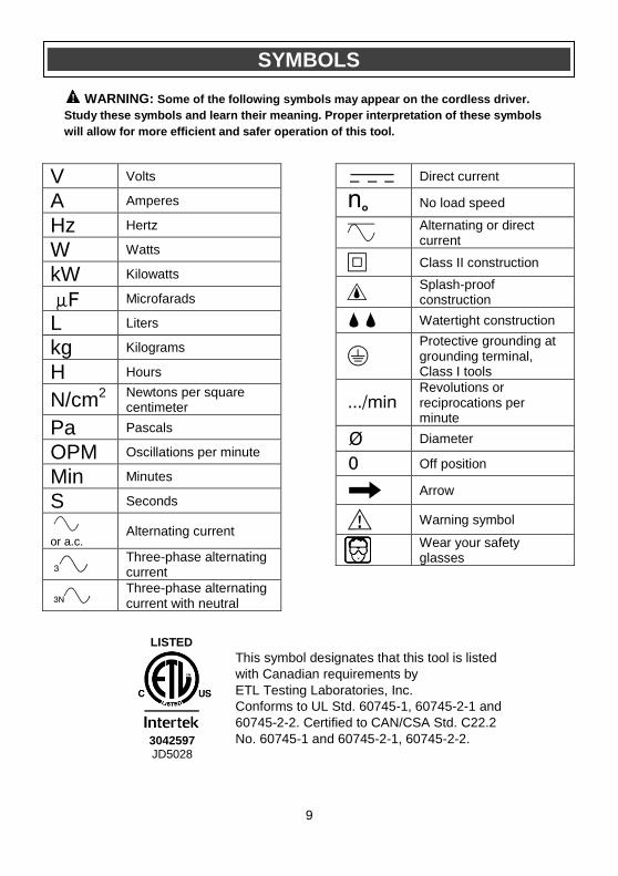
SYMBOLS
WARNING: Some of the following symbols may appear on the cordless driver.
Study these symbols and learn their meaning. Proper interpretation of these symbols
will allow for more efficient and safer operation of this tool.
!

10
KNOW YOUR CORDLESS DRIVER
Single ended screwdriver bits (not shown) #1 & #2 – one each #1 & #2 – one each
Battery charger
Charging plug
Quick release collar
Torque clutch
Forward / reverse switch
Trigger switch
Battery pack
Air vents
Charging receptacle
LED worklight / charging indicator
11
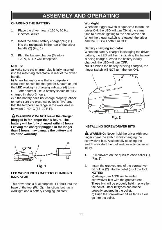
CHARGING THE BATTERY 1. Place the driver near a 120 V, 60 Hz
electrical outlet.
2. Insert the small battery charger plug (1) into the receptacle in the rear of the driver handle (2) (Fig. 1).
3. Plug the battery charger (3) into a 120 V, 60 Hz wall receptacle.
NOTES: a) Make sure the charger plug is fully inserted into the matching receptacle in rear of the driver handle. b) A new battery or one that is completely exhausted should be charged for 5 hours or until the LED worklight / charging indicator (4) turns OFF. After normal use, a battery should be fully charged in about 3 hours. c) If the battery does not charge properly, check to make sure the electrical outlet is "live" and that the temperature range in the work area is between 0–40° C (32–104° F).
WARNING: Do NOT leave the charger plugged in for longer than 5 hours. The battery will be fully charged within 5 hours. Leaving the charger plugged in for longer than 5 hours may damage the battery and void the warranty. LED WORKLIGHT / BATTERY CHARGING INDICATOR This driver has a dual purpose LED built into the base of the tool (Fig. 2). It functions both as a worklight and a battery charging indicator.
Worklight When the trigger switch is squeezed to turn the driver ON, the LED will turn ON at the same time to provide lighting to the screwdriver bit. When the trigger switch is released, the driver and the LED will both turn OFF. Battery charging indicator When the battery charger is charging the driver battery, the LED will flash, indicating the battery is being charged. When the battery is fully charged, the LED will turn OFF. NOTE: When the battery is being charged, the trigger switch will NOT turn the tool ON. INSTALLING SCREWDRIVER BITS WARNING: Never hold the driver with your fingers near the switch while changing the screwdriver bits. Accidentally touching the switch may start the tool and possibly cause an injury. 1. Pull outward on the quick release collar (1)
(Fig. 3).
2. Insert the grooved end of the screwdriver bit holder (2) into the collet (3) of the tool. NOTES: a) Always use ANSI single ended screwdriver bits with the grooved end. These bits will be properly held in place by the collet. Other bit types can not be properly secured in the collet. b) Push the screwdriver bit as far as it will go into the collet.
ASSEMBLY AND OPERATING
!
Fig. 1
Fig. 2
!
12
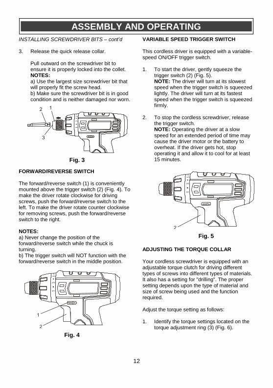
INSTALLING SCREWDRIVER BITS – cont’d 3. Release the quick release collar.
Pull outward on the screwdriver bit to ensure it is properly locked into the collet. NOTES: a) Use the largest size screwdriver bit that will properly fit the screw head. b) Make sure the screwdriver bit is in good condition and is neither damaged nor worn.
FORWARD/REVERSE SWITCH The forward/reverse switch (1) is conveniently mounted above the trigger switch (2) (Fig. 4). To make the driver rotate clockwise for driving screws, push the forward/reverse switch to the left. To make the driver rotate counter clockwise for removing screws, push the forward/reverse switch to the right. NOTES: a) Never change the position of the forward/reverse switch while the chuck is turning. b) The trigger switch will NOT function with the forward/reverse switch in the middle position.
VARIABLE SPEED TRIGGER SWITCH This cordless driver is equipped with a variable-speed ON/OFF trigger switch. 1. To start the driver, gently squeeze the
trigger switch (2) (Fig. 5). NOTE: The driver will turn at its slowest speed when the trigger switch is squeezed lightly. The driver will turn at its fastest speed when the trigger switch is squeezed firmly.
2. To stop the cordless screwdriver, release the trigger switch. NOTE: Operating the driver at a slow speed for an extended period of time may cause the driver motor or the battery to overheat. If the driver gets hot, stop operating it and allow it to cool for at least 15 minutes.
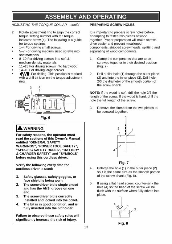
ADJUSTING THE TORQUE COLLAR Your cordless screwdriver is equipped with an adjustable torque clutch for driving different types of screws into different types of materials. It also has a setting for "drilling". The proper setting depends upon the type of material and size of screw being used and the function required. Adjust the torque setting as follows: 1. Identify the torque settings located on the
torque adjustment ring (3) (Fig. 6).
ASSEMBLY AND OPERATING
Fig. 3
Fig. 4
Fig. 5
13
ADJUSTING THE TORQUE COLLAR – cont’d 2. Rotate adjustment ring to align the correct
torque setting number with the torque indicator arrow (4). The following is a guide for torque settings:
1–4 For driving small screws 5–7 For driving medium sized screws into
soft materials 8–10 For driving screws into soft &
medium-density materials 11–13 For driving screws into hardwood 14–16 For driving large screws For drilling. This position is marked
with a drill bit icon on the torque adjustment ring.
PREPARING SCREW HOLES It is important to prepare screw holes before attempting to fasten two pieces of wood together. Proper preparation will make screws drive easier and prevent misaligned components, stripped screw heads, splitting and separating of wood components. 1. Clamp the components that are to be
screwed together in their desired position (Fig. 7).
2. Drill a pilot hole (1) through the outer piece (2) and into the inner piece (3). Drill hole 2/3 the diameter of the smooth portion of the screw shank.
NOTE: If the wood is soft, drill the hole 2/3 the length of the screw. If the wood is hard, drill the hole the full length of the screw. 3. Remove the clamp from the two pieces to
be screwed together.
4. Enlarge the hole (1) in the outer piece (2)
so it is the same size as the smooth portion of the screw shank (Fig. 8).
5. If using a flat head screw, counter-sink the
hole (4) so the head of the screw will be flush with the surface when fully driven into place.
ASSEMBLY AND OPERATING
Fig. 6
For safety reasons, the operator must read the sections of this Owner’s Manual entitled "GENERAL SAFETY WARNINGS", "POWER TOOL SAFETY", "SPECIFIC SAFETY RULES", "BATTERY & CHARGER SAFETY" and "SYMBOLS" before using this cordless driver. Verify the following every time the cordless driver is used:
1. Safety glasses, safety goggles, or face shield is being worn.
2. The screwdriver bit is single ended and has the ANSI groove on one end.
3. The screwdriver bit is correctly installed and locked into the collet.
4. The bit is in good condition, and is fully inserted into the bit holder.
Failure to observe these safety rules will
significantly increase the risk of injury.
WARNING !
Fig. 7
Fig. 8
14
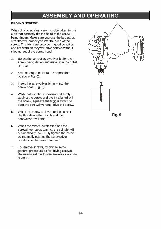
DRIVING SCREWS When driving screws, care must be taken to use a bit that correctly fits the head of the screw being driven. Make sure you use the largest bit size that will properly fit into the head of the screw. The bits must also be in good condition and not worn so they will drive screws without slipping out of the screw head. 1. Select the correct screwdriver bit for the
screw being driven and install it in the collet (Fig. 3).
2. Set the torque collar to the appropriate position (Fig. 6).
3. Insert the screwdriver bit fully into the screw head (Fig. 9).
4. While holding the screwdriver bit firmly against the screw and the bit aligned with the screw, squeeze the trigger switch to start the screwdriver and drive the screw.
5. When the screw is driven to the correct depth, release the switch and the screwdriver will stop.
6. When the switch is released and the screwdriver stops turning, the spindle will automatically lock. Fully tighten the screw by manually rotating the screwdriver handle in a clockwise direction.
7. To remove screws, follow the same general procedure as for driving screws. Be sure to set the forward/reverse switch to reverse.
ASSEMBLY AND OPERATING
Fig. 9
15
GENERAL
WARNING: When servicing this tool,
use only identical replacement parts. The use of any other part may create a hazard or cause product damage. DO NOT use solvents when cleaning plastic parts. Plastics are susceptible to damage from various types of commercial solvents and may be damaged by their use. Use a clean cloth to remove dirt, dust, oil, grease etc.
WARNING: Do not allow brake fluids, gasoline, petroleum-based products, penetrating oils, etc. to come into contact with plastic parts. They contain chemicals that can damage, weaken or destroy plastic. DO NOT abuse power tools. Abusive practices can damage the tool and the workpiece.
WARNING: DO NOT attempt to modify tools or create accessories. Any such alteration or modification is misuse and could result in a hazardous condition leading to possible serious injury. It will also void the warranty. LUBRICATION All of the bearings in this tool are lubricated with a sufficient amount of high-grade lubricant for the life of the unit under normal conditions. Therefore, no further lubrication is required LITHIUM-ION BATTERY PERFORMANCE Lithium-ion rechargeable batteries generally provide superior performance to nickel-cadmium batteries when used in power tools.
● Faster charges
● Longer battery life
● More power
● Lighter weight Lithium-ion batteries perform best and deliver peak output power at room temperature (20° C or 68° F). When operated in lower temperatures, the battery output will be reduced and it will NOT function below –20° C (-4° F). The output power will increase as the heat generated by the
battery during use increases the internal temperature of the battery. The result is increased power as the tool is used. LITHIUM-ION BATTERY MAINTENANCE Lithium-ion batteries share many characteristics with Nickel-Cadmium batteries. The major characteristic that is NOT shared with Nickel-Cadmium batteries is that Lithium-ion batteries do not have a “memory” and do not require to be completely discharged periodically. It is recommended that you charge your Lithium-ion batteries after each use so they will be fully charged when needed. NOTE: A fully charged battery will loose about 2% of its charge per month during storage. BATTERY PACK REMOVAL AND PREPARATION FOR RECYCLING To preserve our natural resources, please recycle or dispose of batteries properly. The batteries supplied with this tool may contain chemicals and metals that are harmful to the environment. Never dispose of rechargeable batteries in your normal household garbage or in landfill sites because they will add to the pollution of the environment. Consult your local waste authority for information regarding available recycling and disposal options.
WARNING: Upon removal of the battery
pack, cover the terminals of the battery pack with electrical tape or heavy-duty adhesive tape. Never touch both terminals with metal objects or body parts, because a short circuit may result. Keep away from children. Do not attempt to destroy or disassemble battery pack or remove any of its components. Rechargeable batteries must be recycled or disposed of properly. Failure to comply with these warnings could result in fire and serious injury.
MAINTENANCE
!
!
!
!
16
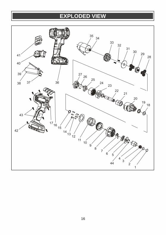
EXPLODED VIEW
17
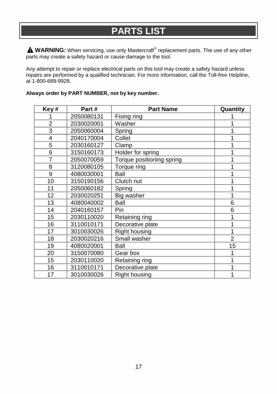
PARTS LIST
WARNING: When servicing, use only Mastercraft® replacement parts. The use of any other
parts may create a safety hazard or cause damage to the tool. Any attempt to repair or replace electrical parts on this tool may create a safety hazard unless repairs are performed by a qualified technician. For more information, call the Toll-free Helpline, at 1-800-689-9928. Always order by PART NUMBER, not by key number.
!
Key # Part # Part Name Quantity
1 2050080131 Fixing ring 1
2 2030020001 Washer 1
3 2050060004 Spring 1
4 2040170004 Collet 1
5 2030160127 Clamp 1
6 3150160173 Holder for spring 1
7 2050070059 Torque positioning spring 1
8 3120080105 Torque ring 1
9 4080030001 Ball 1
10 3150190156 Clutch nut 1
11 2050060182 Spring 1
12 2030020251 Big washer 1
13 4080040002 Ball 6
14 2040160157 Pin 6
15 2030110020 Retaining ring 1
16 3110010171 Decorative plate 1
17 3010030026 Right housing 1
18 2030020216 Small washer 2
19 4080020001 Ball 15
20 3150070080 Gear box 1
15 2030110020 Retaining ring 1
16 3110010171 Decorative plate 1
17 3010030026 Right housing 1
18
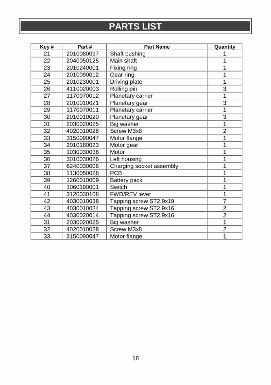
PARTS LIST
Key # Part # Part Name Quantity
21 2010080097 Shaft bushing 1
22 2040050125 Main shaft 1
23 2010240001 Fixing ring 1
24 2010090012 Gear ring 1
25 2010230001 Driving plate 1
26 4110020003 Rolling pin 3
27 1170070012 Planetary carrier 1
28 2010010021 Planetary gear 3
29 1170070011 Planetary carrier 1
30 2010010020 Planetary gear 3
31 2030020025 Big washer 1
32 4020010028 Screw M3x8 2
33 3150090047 Motor flange 1
34 2010180023 Motor gear 1
35 1030030038 Motor 1
36 3010030026 Left housing 1
37 6240030006 Charging socket assembly 1
38 1130050028 PCB 1
39 1260010009 Battery pack 1
40 1060190001 Switch 1
41 3120030108 FWD/REV lever 1
42 4030010038 Tapping screw ST2.9x19 7
43 4030010034 Tapping screw ST2.9x16 2
44 4030020014 Tapping screw ST2.9x16 2
31 2030020025 Big washer 1
32 4020010028 Screw M3x8 2
33 3150090047 Motor flange 1

19
3-Year Limited Warranty This Mastercraft® product is guaranteed for a period of three (3) years from the
date of original retail purchase against defects in workmanship and materials, except for the following components:
a) Component A: Batteries, chargers and carrying cases, which are guaranteed for a period of two (2) years from the date of original retail
purchase against defects in workmanship and materials; b) Component B: Accessories which are guaranteed for a period of 1 year
from the date of original retail purchase against defects in workmanship and materials.
Subject to the conditions and limitations described below, this product, if returned to us with proof of purchase within the stated warranty period and is covered under this warranty, will be repaired or replaced (with the same model, or one of equal value or specification),at our option. We will bear the cost of any repair or replacement and any costs of labour relating thereto. These warranties are subject to the following conditions and limitations:
a) A bill of sale verifying the purchase and the purchase date must be provided;
b) This warranty will not apply to any product or part thereof that is worn, broken or that has become inoperative due to abuse, misuse, accidental damage, neglect or lack of proper installation, operation or maintenance (as outlined in the applicable owner’s manual or operating instructions) or that is being used for industrial, professional, commercial or rental purposes;
c) This warranty will not apply to normal wear and tear or to expendable parts or accessories that may be supplied with the product that are expected to become inoperative or usable after a reasonable period of use;
d) This warranty will not apply to routine maintenance and consumable items such as, including but not limited to, fuel, lubricants, vacuum bags, blades, belts, sandpaper, bits, fluids, tune-ups or adjustments;
e) This warranty will not apply where damage is caused by repairs made or attempted by others (i.e.: persons not authorized by the manufacturer);
f) This warranty will not apply to any product that was sold to the original purchaser as a reconditioned or refurbished product (unless specified otherwise in writing);
Page 1 of 2
20
Rev 1.3 11/07/2012
3-Year Limited Warranty – cont’d These warranties are subject to the following conditions and limitations:
g) This warranty will not apply to any product or part thereof if any part from another manufacturer is installed therein or any repairs or alterations have been made or attempted by unauthorized persons;
h) This warranty will not apply to normal deterioration of the exterior finish, such as, including but not limited to, scratches, dents, paint chips, or to any corrosion or discoloring by heat, abrasive and chemical cleaners; and
i) This warranty will not apply to component parts sold by and identified as the product or company, which shall be covered under the product manufacturer’s warranty, if any.
Additional Limitations
This warranty applies only to the original purchaser, and cannot be transferred. Neither the retailer not the manufacturer shall be liable for any other expense, loss or damage, including, without limitation, but not limited to any indirect, incidental, consequential or exemplary damages arising in connection with the sale, use or inability to use this product. Notice to Consumer
This warranty gives you specific legal rights, and you may have other rights, which may vary from province to province. The provisions contained in this warranty are not intended to limit, modify, take away from, disclaim or exclude any statutory warranties set forth in any applicable provincial or federal legislation. Mastercraft® is a superior line of products selected for their workmanship and materials. These products are designed to meet rigorous quality and performance standards, and are approved by our Quality Assurance laboratory.
TOLL-FREE HELPLINE: 1-800-689-9928
Page 2 of 2