Embed Size (px)
Citation preview
f 8ThMENZ
D~uulu~aaUaflmtCd

UNCLASSIFIEDSECaRITY CLASSIFICATION OF THIS PAGE
Form ApprovedREPORT DOCUMENTATION PAGE OM No. 070 188
la. REPORT SECURITY CLASSIFICATION lb. RESTRICTIVE MARKINGSUnclassified
2a. SECURITY CLASSIFICATION AUTHORITY 3. DISTRIBUTION /AVAILABILITY OF REPORTApproved for public release;
2b. DECLASSIFICATION /DOWNGRADING SCHEDULE distribution is unlimited
4. PERFORMING ORGANIZATION REPORT NUMBER(S) S. MONITORING ORGANIZATION REPORT NUMBER(S)
NTIAC-85-26a. NAME OF PERFORMING ORGANIZATION 6b. OFFICE SYMBOL 7a. NAME OF MONITORING ORGANIZATIONNTIAC (if applicable)
Southwest Research Institute U.S. Army Aviation Systems Command6c. ADDRESS (City, State, and ZIP Code) 7b. ADDRESS (City, State, and ZIP Code)P.O. Drawer 28510 Depot Engineering & RCM Support OfficeSan Antonio, TX 78284 CCAD
Corpus Christi, TX 78419-61958a. NAME OF FUNDING/SPONSORING |8b. OFFICE SYMBOL 9. PROCUREMENT INSTRUMENT IDENTIFICATION NUMBER
ORGANIZATIONj (If applicable)
Defense Logistics Agency DTIC-DF DLA900-84-C-0910, CLIN O001AJ8c. ADDRESS (City, State, and ZIP Code) 10. SOURCE OF FUNDING NUMBERS
PROGRAM PROJECT ITASK WORK UNITCameron Station ELEMENT NO. NO. NO- ACCESSION NO.Alexandria, VA 22304
11 TITLE (Include Security Classification)
ACE/AACE Inspection and Analysis Handbook '12. PERSONAL AUTHOR(S) ,D.C. Brauer, D. Henry, G.A. Matzkanin
13a. TYPE OF REPORT 13b. TIME COVERED 14. DATE OF REPORT (Year, Month, Day) 1S. PAGE COUNTHandbook FROMA627/84 TO6/0/5 June 30, 1985 126
16. SUPPLEMENTARY NOTATION
Prepared as a Special Task for the Nondestructive Testing Information Analysis Center.17. COSATI CODES 18. SUBJECT TERMS (Continue on reverse if necessary and identify by block number)
FIELD GROUP SUB-GROUP -Aircraft Inspection, Reliability,/ Nondestructive Testing Maintainability
|Depot Maintenance/ Corrosion,V ABSTRACT (Continue on reverse if necessary and identify by block number)
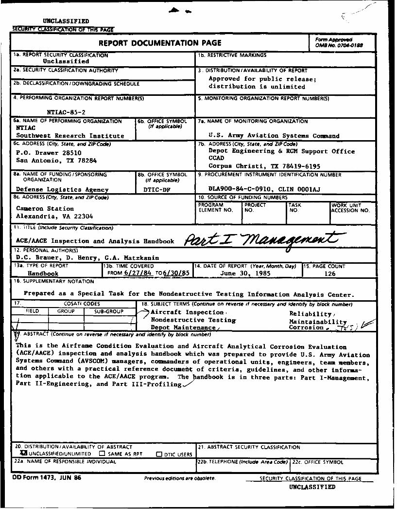
This is the Airframe Condition Evaluation and Aircraft Analytical Corrosion Evaluation(ACE/AACE) inspection and analysis handbook which was prepared to provide U.S. Army AviationSystems Command (AVSCOM) managers, commanders of operational units, engineers, team members,and others with a practical reference documeot of criteria, guidelines, and other informa-tion applicable to the ACE/AACE program. The Jandbook is in three parts: Part I-Management,Part Il-Engineering, and Part III-Profiling,7
20. DISTRIBUTION/AVAILABILITY OF ABSTRACT 21. ABSTRACT SECURITY CLASSIFICATION13 UNCLASSIFIED/UNLIMITED C3 SAME AS RPT C DTIC USERS
22a. NAME OF RESPONSIBLE INDIVIDUAL 22b. TELEPHONE (Include Area Code) I 22c. OFFICE SYMBOL
D Form 1473, JUN 86 Previous editions are obsolete. SECURITY CLASSIFICATION OF THIS PAGE
UNCLASSIFIED
NTIAC-85-2
ACE/AACE INSPECTION AND ANALYSIS
HANDBOOK
PART I - MANAGEMENT
ARkf
DEPOT ENGINEERING
~OFIC
(CRPL%(*HRITI. TX.
Prepared as a Special Task under the auspices of the -
Nondestructive Testing Information Analysis Centerfor
U.S. ARMY AVIATION SYSTEMS COMMAND
APRIL 1985
FOREWORD
It is the policy of the U.S. Army Aviation Systems Command (AVSCOM Reg750-7) that an airframe condition evaluation and aircraft analytical corrosion eval-uation (ACE/AACE) be performed annually on all first line/mission essential Armyaircraft worldwide. ACE/AACE is part of AVSCOM's On-Condition Maintenance(OCM) program. OCM is a maintenance concept designed for the purpose of se-lecting Army aircraft for depot maintenance. ACE involves an annual structuralevaluation of each aircraft in the operational fleet to identify those that are in thegreatest need of depot maintenance; it is performed in accordance with the require-ments of AVSCOM Pamphlet series 750-1. AACE, a special corrosion evaluationprogram, was established as a companion to ACE and is performed in accordancewith AVSCONl Pamphlet series 750-2.
*This handbook is intended to provide AVSCOM managers, commanders of
operational units, ACE/AACE engineers, ACE/AACE team members, and othersinvolved in ACE/AACE with a practical reference document of criteria, guidelines, r .. ..and other information applicable to the ACE/AACE program. The handbook isorganized into three parts, each bound separately.
Part I (Management) is directed to AVSCOM managers, commanders of op-erational units, and other managers responsible for the use, maintenance and op-erational readiness of fielded U.S. Army aircraft. It provides an overview of Armyaircraft maintenance and gives other general information pertaining to the purposeand substance of the ACE/AACE program and the closely related reliability-cen-tered maintenance (RCM) discipline, thus establishing a framework for performingthe engineering and profiling tasks addressed in Part II and Part Ill.
Part II (Engineering) is directed to ACE/AACE engineers and others who areinvolved in planning and analysis in the ACE/AACE program. It provides a readyreference of general information pertaining to ACE/AACE methodology, the se-."..........lection and revision of indicators, the analysis of field profiling data, and thedetermination of optimum engineering thresholds. Guidelines are included for theidentification of new indicators to be incorporated into AVSCOM Pamphlet series750-1 and 750-2.
Part III (Profiling) is directed to ACE/AACE team members and others whoare involved in profiling in the ACE/AACE program. It provides a ready referenceof general information pertaining to aircraft evaluation and inspection.
041
This handbook was prepared by Reliability Technology Associates (RTA) as aSpecial Task under the auspices of the Nondestructive Testing Information AnalysisCenter (NTIAC) at Southwest Research Institute (SwRI) under Contract No.DLA900-84-C-0910, CLIN 0001A. At RTA, Mr. Douglas C. Brauer compiled andorganized the technical material and developed the handbook under the overalltechnical direction of Dr. Daniel Henry. Final editorial preparation and publicationwas performed by NTIAC under the direction of Dr. George A. Matzkanin andTechnical Publication Specialist, Mr. Don Moore.
On the part of the AVSCOM, the project was under the technical managementof Mr. Lewis Neri, Chief, Depot Engineering and RCM Support Office. Mr.Thomas R. Tullos guided the development of this handbook and provided thenecessary Army pamphlets, forms, and other information used as input.
This handbook is for reference only and does not in any way supercede orsupplement any official Army document, specifically the 750-1 and 750-2 Pamphletseries. Revision and updating of the handbook is envisioned at appropriateintervals.
The proponent of this publication is HQ, AVSCOM. Users are invited to sendcomments to the Depot Engineering and RCM Support Office, Attn: AMSAV-7,Corpus Christi, TX 78419-6195.
AccOOSsion For
1-TIS GRA&I 'DTICTAB 0UznannO1Jfled QOjustiLf ication ,, J--- -... .•.. .....
ByDistribution/
Availability Codes[Avail ad/or
Dist Special
iv

HANDBOOK CONTENTS
PAGE
FO RE W O R D .............................................................................. i
PART I - MANAGEMENT
1.0 BACKG ROUND ................................................................ I* Overview of Army Aircraft Maintenance ............................... I
Figure 1-1 Arm y M aintenance Levels ............................................ 1* Reliability Centered Maintenance (RCM) .............................. 3
2.0 INTRODUCTION TO ACE/AACE ........................................ 7Figure 2-1 ACE/AACE Program ..................................... 8
Figure 2-2 Pareto Distribution curve ............................................... 9Figure 2-3 Profile Index Distribution and Thresholds .......................... 11
3.0 MANAGING OCM/ACE/AACE ........................................... 13 - . -
* The Depot Induction Process ............................................. 13* M anagem ent Responsibilities ............................................. 14
4.0 ORGANIZING FOR THE FUTURE ...................................... 19
PART II - ENGINEERING Bound Separately
1.0 INTRODUCTION TO PART II - ENGINEERING
2.0 ACE/AACE METHODOLOGY
3.0 INDICATORS SELECTION
4.0 DETERMINATION OF PROFILE INDEX AND THRESHOLD
APPENDIX A - Army Aircraft Logbook ListAPPENDIX B - Aircraft Audit WorksheetsAPPENDIX C - World Traveler Data
V
PART III - PROFILING Bound Separately
1.0 INTRODUCTION TO PART III
2.0 ACE PROFILING GUIDELINES
3.0 AACE PROFILING GUIDELINES
APPENDIX A - Forms and Completion DataAPPENDIX B - Army Aircraft Logbook ListAPPENDIX C - Corrosion Forms and CausesAPPENDIX D - World Traveler Data
I
vii

1.0 BACKGROUND
The achievement of an effective On-Condition Maintenance (OCM) program,based on airframe condition evaluation (ACE) and aircraft analytical corrosionevaluation (AACE), requires careful planning followed by well executed aircraftevaluations, inspections, and engineering analyses. OCM/ACE/AACE is conductedas an integral part of the overall Army aircraft maintenance system and functionswithin the reliability-centered maintenance (RCM) process. This first part of thehandbook presents an overview of the Army maintenance system and describes theRCM piocess as it is being implemented by AVSCOM. With this background, theACE/AACE program is then introduced, the responsibilities of the various AV-SCOM Directorates are outlined, and a brief discussion on some of the majorthrusts that will shape the maintenance system in the immediate future is presented.
This first part is designed to be compatible with the other two parts of thehandbook. Part II provides specific guidelines to aid in the selection and revisionof ACE/AACE indicators, the analysis of field profiling data, and the determi-nation of optimum engineering thresholds. Part III provides specific guidelines toaid in the actual evaluation and inspection of operational aircraft.
Overview of Army Aircraft Maintenance
Army aircraft are maintained within a three-level maintenance concept (FigureI-1). The first level, aviation unit maintenance (AVUM), consists primarily of pre-ventive maintenance and associated minor repairs and component replacement. Thesecond level, aviation intermediate maintenance (AVIM), consists of maintenancetasks which exceed AVUM capabilities, such as the performance of specialized air-craft inspections and the repair of certain components. The third level, depot main-tenance, consists of those maintenance tasks which exceed AVUM and AVIMcapability.
OpeAraatinal tUri.ato.
-c- pr n Ir nttfcl a All AVU p Tsk LX, iantenance R palirlReplacroe , nc • icrf yllm ,Aligtosen
M lodule Repl ar ent v Adanc/1Cl/fb-u.otor .ep .r .. Don ln p t. .
Figure 1-1 ZA Mainteinaclel n, AA,
•~~~ Direct Exchangel (DX) Programlh A'd
With AV[H
?ro rallied Depot -a-1 ... nc mmlm
Love! Three
D.. M-no ......erlu/Rbu
"- 1: 1110 1e 1 111toni
Figure 1-1 Army Maintenance Levels
Depot maintenance is carried out in accordance with Depot Maintenance WorkRequirements (DMWRs), documents which establish requirements for disassembly,cleaning, inspection, repair, reconditioning, rehabilitation, modification, reassem-bly, servicing, testing, and storage of assemblies or parts.
The three level maintenance concept is implemented in concert with the Army'sRCM program. RCM involves application of a decision logic process that employssystematic analysis of failure mode, rate, and criticality data in establishing themost effective maintenance program for an aircraft system. RCM was initially struc-tured by the airlines in the early 1970s as a broadly applicable new philosopy ofmaintenance, endorsed by the Air Transport Association (ATA), the AerospaceManufacturers Association (AMA), and the Federal Aviation Administration(FAA). The concept has been referred to as MSG-2 and more recently, in a revisedform, as MSG-3. MSG represents the Management Steering Group, an airline in-dustry body which originally formulated the RCM concept.
RCM, as it is now structured within the Department of Defense (DoD), seg-regates maintenance actions into three distinct categories: (!) hardtime, or sched-uled, maintenance actions; (2) maintenance actions based upon condition monitor-ing sensors or indicators; and (3) maintenance determined to be necessary "on-condition", i.e., as determined during a scheduled inspection or screening. Main-tenance resulting from this third category is called "on-condition maintenance"(OCM).
Within the U.S. Army Aviation Systems Command (AVSCOM), the OCMconcept is used as a management tool in selecting aircraft for depot maintenanceand thereby making depot operations more cost effective. As a management tool,OCM provides srheduling flexibility not obtainable through other programs. Thisflexibility provides a readily adaptable program that can be tailored to the particularneeds of the user. The most significant by-product of the program is the benefit .. --
derived by the individual fleet managers who can draw upon more current andtimely information for making management decisions. Valuable data on the con-dition of the airframe are collected under OCM. Maintenance data are also recordedas repairs are performed on the items. These data provide an up-to-date and realisticassessment of depot repairs and the OCM program. They also help to identify thedesign deficiencies of items and lend themselves to the support of the ProductImprovement Program (PIP), Engineering Change Proposals (ECP), and othercorrectiv( ictions. All of these provide a basis for realistic projection of budget anddepot resource requirements.
2
The ACE/AACE program was established as an OCM technique to provide ameaningful and inexpensive method for ranking the aircraft within the fleet ascandidates for depot level maintenance. It involves a particular approach to OCMin which the state of an aircraft is deduced from a carefully designed profilingtechnique which can be effectively carried out by trained personnel.
Within the ACE/AACE program, the aircraft which need repair or recondi-tioning are identified using noninvasi,,e techniques. The noninvasive visual condi-tion inspection technique used in ACE involves an evaluation of the structuralintegrity of the aircraft in terms of certain thoughtfully selected parameters, calledindicators. Typical indicators include the condition of the main lift beam, the nosefuselage skin, and the upper bulkhead, and the state of the corrosion protection.Weights are then assigned to each of the indicators using ranking and distributiontechniques.
AACE, as a companion to ACE, provides a method of selecting aircraft ascorrosion candidates for depot level repair. The basic aircraft structure is examinedfor corrosion defects together with an assessment of the external areas of compo-nents, both structural and dynamic, for deterioration caused by corrosion. AACEpertains principally to fuselage structural members t' at are replaceable at the depot,but also pertains to dynamic components and component structures.
ACE/AACE relies on other RCM data in the selection, development, andreview of indicators. Further knowledge of the RCM process, then, is necessary fora full understanding of ACE/AACE.
Reliability-Centered Maintenance (RCM)
- - RCM is based on the premise that reliability is an inherent design characteristicto be realized and preserved during operational life. The philosophy asserts, fur-thermore, that efficient and cost-effective life-time maintenance and logistic supportprograms can be developed using a well disciplined decision logic which focuses onthe consequences of failure. The resultant maintenance program provides the de-sired or specified levels of operational safety and reliability at the lowest possibleoverall cost.
The RCM analysis process uses a rigorously defined approach in analyzingreliability to highlight maintenance problem areas for consideration and for estab-lishing the most effective preventive maintenance program for the system. RCMidentifies specific preventive maintenance tasks and requirements for:
3
* Detecting and correcting incipient failures either before they occur orbefore they develop into major defects,
* Reducing the probability of failure,• Detecting hidden failures that have uccurred, and* Increasing the cost effectiveness of the system's maintenance program.
As previously discussed, RCM, as it is now generally structured within DoD,segregates maintenance requirements into three categories:
(1) On-Condition Maintenance (OCM) requirements - scheduled inspection "-or tests designed to measure deterioration of an item. Based on thedeterioration of the item, either corrective maintenance is performed orthe item remains in service.
(2) Hard Time Maintenance requirements - scheduled removal at predeter-mined fixed intervals of age or usage.
(3) Condition Monitoring requirements - unscheduled tests or inspectionson components where failure can be tolerated during operation of thesystem or where impending failure can be detected through routine mon-itoring during normal operation.
RCM is based upon the following criteria:
(1) Scheduled maintenance tasks should be performed on noncritical com-ponents only when performance of the scheduled tasks will reduce thelife-cvcle cost of ownership of the system/equipment.
(2) Scheduled maintenance tasks should be performed on critical compo-nents only when such tasks will prevent a decrease in reliability and/ordeterioration of safety to unacceptable levels or when the tasks willreduce the life-cycle cost of ownership of the system/equipment.
The RCM process is intended for application once the system's significant _........parameters (i.e. component failure modes, their effects, and criticaly) have beenidentified. Traditionally, these parameters have been identified by conducting afailure mode, effects, and criticality analysis (FMECA) as part of design-relatedreliability engineering activities. The FMECA, by identifying the system and com-ponent failure modes, provides the basis for defining detailed preventive and/orcorrective maintenance requirements to be applied during system operation.
It is also recognized that, while a maintenance program conceived during designand production suffers from a lack of hard field experience, the program must be
4
in place at the time of delivery of the first production systems to their users. Tocope with this dilemma, it is necessary to upgrade an existing maintenance programto accommodate the net results of Army field data collection programs and oper-ational experiences applicable to specific systems. One effective method for accom-plishing this objective is to augment this process through the use of fault treeanalysis (FTA). FTA can be used to apply actual field data to the improvement ofan existing maintenance program and thus improve the RCM process.
Regardless of when it is applied, RCM derived maintenance programs makeuse of a logic process (using logic diagrams) to establish the set of maintenanceactivities. Presently, RCM logic diagrams, as used by the Army in general, arereferenced for Army systems in two documents. The RCM logic diagram for fieldedsystems is given in DOA Pamphlet 750-40 and the logic diagram for applicationduring the full scale development phase on new systems is given in AMC Pamphlet750-16. Both diagrams are structured to lead (through the answering of severalquestions) to a decision identifying one of the three preventive maintenanceactivities.
AVSCOM's RCM process meets the provisions of AMC Pamphlet 750-16 andinvolves application of the following eight steps:
Step I: Determine Maintenance Significant ItemsStep 2: Acquire Failure/Repair DataStep 3: Develop FMECA/Fault Tree Analysis (FTA) DataStep 4: Apply Decision Logic to Catastrophic and Critical Failure
ModesStep 5: Use FMECA/FTA Data to Help Answer Decision Logic Ques-
tions.-. -Step 6: Compile/Record Maintenance Classification
-Hard Time- On-Condition- Condition Monitoring
Step 7: Implement RCM Decisions- Depot Maintenance Work Requirements (DMWRs)- Phase Maintenance- Programmed Depot Maintenance (PDM)- Preshop Analysis (PSA)- Army Oil Analysis Program (AOAP)
Step 8: Apply sustaining engineering based on actual experience data,eliminate default decisions, provide audit trail and assessment.
5
AVSCONI has structured a new RCM decision logic, based on MSG-3, and acompanion FTA-based safety analysis model specifically for Army aircraft. To im-plement the RCM process based on this new decision logic and safety analysismodel, AVSCOM uses the "Automated Army Aircraft RCM," (A3RCM) computersoftware package. A3RCM provides the capability to rapidly develop a uniform andcomplete RCM-based maintenance program from standard, readily available inputsources. It provides a maintenance history for each aircraft where requirements arecorrelated to specific parts and their failure modes. It assures that all maintenancesignificant parts and failure modes are considered in the development of the main-tenance requirements for an aircraft.1
I ,
IFurther information on the new RCM decision logic and safety analysis model andthe companion computer software package is available in two reports prepared byReliability Technology Associates for AVSCOM: "Application of RCM to the T53-L-13B Engine," May 1984 and "Automated Army Aircraft RCM Analysis," Sep-tember 1984.
6
2.0 INTRODUCTION TO ACE/AACE
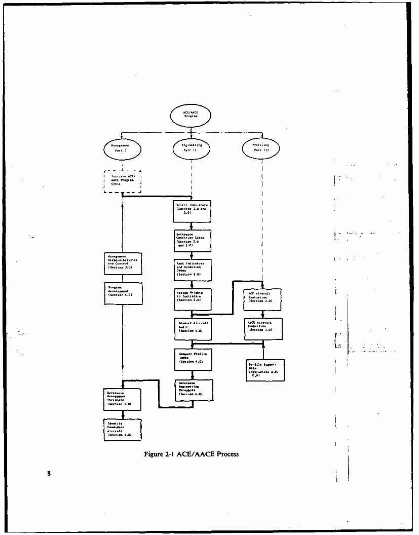
As a part of the implementation of reliability-centered maintenance (RCM),the on-condition maintenance (OCM) concept is implemented within Army aviationby the use of profiling techniques for evaluating the condition of aircraft and foridentifying items most in need of depot attention. These techniques, known asairframe condition evaluation (ACE) and aircraft analytical corrosion evaluation(AACE), are performed in accordance with the requirements of AVSCOM Regu-lation 750-7 and the 750-1 and 750-2 Pamphlet series published by the Depot En-gineering and RCM Support Office. The overall ACE/AACE process is illustratedin Figure 2-1. The figure also identifies the location of the various concepts, bypart and section, within the handbook.
ACE uses for its evaluation a representative list of indicators of structuralcondition selected for each aircraft type. Each indicator is further defined by con-dition codes which depict the condition of the indicator, i.e., no defect, cracked,buckled, etc. Results are recorded on special worksheets provided in the 750-1Pamphlet series. ACE is performed annually on all first line/mission essential Armyaircraft worldwide in accordance with AVSCOM Regulation 750-7.
AACE, a special corrosion structural examination, is a companion to the ACEprogram and is performed annually on each operational aircraft during ACE. Ituses a representative list of indicators on corrosion only and has condition codesfor degree of corrosion severity. One or two team members go with the ACE team,using separate worksheets (provided in the 750-2 Pamphlet series) analogous to theACE worksheets. The AACE data, like ACE data, are submitted to the DepotEngineering and RCM Support Office.
The process of identification, selection, and review of indicators is a key ele-ment of the ACE/AACE process. Indicators are developed by ACE/AACE engi-neers who conduct a thorough analysis on the specific aircraft involved. As part of. .............the selection process, four criteria are considered: aeronautical importance, depotcapability, accelerated deterioration, and general deterioration. Those which havesignificant impact are identified as indicators for that particular aircraft. In orderto avoid any extensive airframe disassembly or the use of cumbersome and overlycomplex equipment in the field as part of the ACE/AACE process, indicatorsselected are those through which structural integrity can be readily inferred. Acorresponding list of condition codes is then developed for each indicator to denotethe pertinent range of severity encountered. The number of indicators for differentaircraft varies from 40-50 and the condition codes from I and 9. In each case, thetwo lists are continually reviewed and updated to reflect current field experienceand changing depot capability.
7
Initial, ACII
AACE P,.I,-C"J.
v
(Section 2.0 and
C.(;:d i
t in" ZCdc t ion .0
and 3.03
M..., -- - c
and Control lank Indicator.
(S ..... 3.0) and ConditionCod a
(Section 2.0)
(Section 4.0) Act Aircr:ftled ter. .1
(See Ev " t i
tio. 2.0) (Section 2.0)
Conabact Aircraft AACX Airtcraft
A" it
I-P..ti-
(Stti- 4.0) (Section 3.0)
Co." . ft.(:I.I.=(Seetion, 4.0
(API-dic.. A.&.C..)
"Bodeing6.0)(Section 3.0)
Figure 2-1 ACE/AACE Process
8
40-50 and the condition codes from I and 9. In each case, thc iwo lists are contin-ually reviewed and updated to reflect current field experience and changing depotcapability.
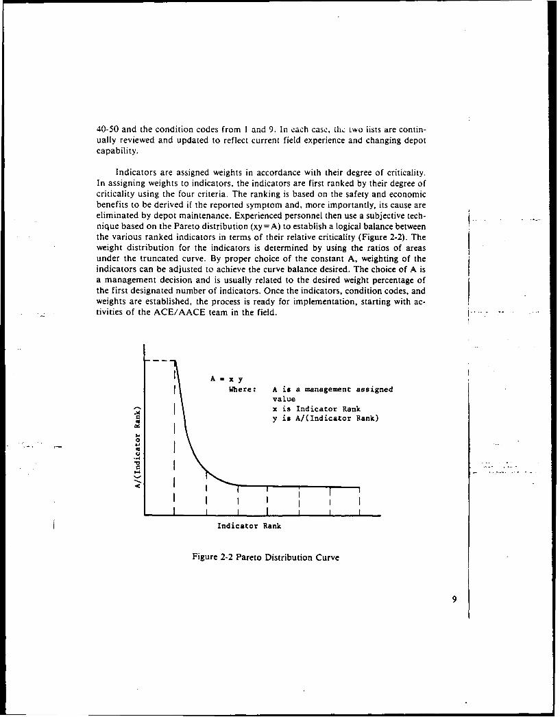
Indicators are assigned weights in accordance with their degree of criticality.In assigning weights to indicators, the indicators are first ranked by their degree ofcriticality using the four criteria. The ranking is based on the safety and economicbenefits to be derived if the reported symptom and, more importantly, its cause areeliminated by depot maintenance. Experienced personnel then use a subjective tech-nique based on the Pareto distribution (xy = A) to establish a logical balance betweenthe various ranked indicators in terms of their relative criticality (Figure 2-2). Theweight distribution for the indicators is determined by using the ratios of areasunder the truncated curve. By proper choice of the constant A, weighting of the
indicators can be adjusted to achieve the curve balance desired. The choice of A isa management decision and is usually related to the desired weight percentage ofthe first designated number of indicators. Once the indicators, condition codes, andweights are established, the process is ready for implementation, starting with ac-tivities of the ACE/AACE team in the field.
I A=xy
Where: A is a management assignedvaluex is Indicator Rank
ry is A/(Indicator Rank)
0
I I I I I I I
Indicator Rank
Figure 2-2 Pareto Distribution Curve
9
A trained ACE/AACE team conducts an annual evaluation of each aircraft'scondition, using the established indicator and condition codes, and determines itsprofile in accordance with the applicable AVSCOM 750-1 and 750-2 Pamphlets.Each aircraft (designated by its tail number) is profiled by noting any faulty indi-cators in terms of their worst condition code (degree of severity). The team doesnot attempt to assign weights or make any other computation in the field. The VACE/AACE profiling does not require a complete technical inspection of the air-craft and, therefore, does not duplicate any other scheduled inspections requiredto be performed by the owning unit's regularly assigned personnel, nor can it beconstrued as such. However, any safety-of-flight discrepancies noted by the teamare verbally brought to the attention of the owning unit, and responsibility foraction rests there. The activities of the ACE/AACE team are limited to its specificdefined function and do not constitute an evaluation of the field unit's maintenancecapability or performance. The data collected by the ACE/AACE team creates adata base whereby better management decision and actions can be derived through - .engineering analysis.
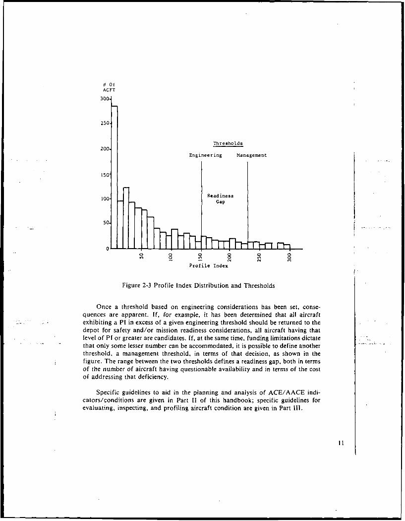
After the field evaluation, the condition of each aircraft in the fleet is computedin terms of a numerical value known as the profile index (PI). The higher the profileindex is, the worse is the condition of the aircraft. A PI distribution is then gen-erated as shown in Figure 2-3 where aircraft population is plotted against PI value.This type of presentation provides a concise ranking profile of the entire fleet andpermits the necessary management decisions to be approached in a straightforwardmanner. With the aircraft ranked by their need for repair, criteria for determiningwhich aircraft are depot candidates are developed. The establishment of a thresholdfor the induction of aircraft into depot maintenance is a key area in the ACEprogram since it determines the operational acceptance level for the airframes ofthe active fleet. A threshold is expressed in terms of Pl. Once an aircraft's PI .reaches or exceeds its threshold, it becomes a candidate for depot repair. Variousdifferent evaluation criteria can be used to establish a threshold, such as safety,mission capability, availability for readiness, reliability, depot facility, or economicconsiderations. The threshold is a powerful discriminator. The condition of theentire fleet as well as the money spent on depot repair is affected by the thresholdvalue. If management decisions change, then the threshold must be reevaluated.
10i
101
# OfACFT
300.
250
Thresholds200.
Engineering Management
150"
100- Readiness100Gap
50.
0 0 0 0 0 00 0 a
Profile Index
Figure 2-3 Profile Index Distribution and Thresholds
Once a threshold based on engineering considerations has been set, conse-quences are apparent. If, for example, it has been determined that all aircraftexhibiting a PI in excess of a given engineering threshold should be returned to thedepot for safety and/or mission readiness considerations, all aircraft having thatlevel of PI or greater are candidates. If, at the same time, funding limitations dictatethat only some lesser number can be accommodated, it is possible to define anotherthreshold, a management threshold, in terms of that decision, as shown in thefigure. The range between the two thresholds defines a readiness gap, both in termsof the number of aircraft having questionable availability and in terms of the costof addressing that deficiency.
Specific guidelines to aid in the planning and analysis of ACE/AACE indi-cators/conditions are given in Part 11 of this handbook; specific guidelines forevaluating, inspecting, and profiling aircraft condition are given in Part Ill.
I1
3.0 MANAGING OCM/ACE/AACE
The Depot Induction Process
The Airframe Condition Evaluation (ACE)/Aircraft Analytical CorrosionEvaluation (AACE) program identifies aircraft candidates for depot repair. It pro-vides a priority-of-need list, based on the condition of the aircraft, organized byaircraft type, tail number, geographic area, and command. The actual selection ofaircraft for depot repair is made in the broader context of the Reliability-CenteredMaintenance (RCM)/On-Condition Maintenance (OCM) program. It is made onlyafter a complete review of all aircraft within a command. Only those aircraft whosePis exceed a specified threshold are considered as OCM candidates. Requirementsfor the aircraft depot program are based on the quantity of aircraft with profilesover a specified threshold. Actual requirements are established at the annual World-wide Aviation Logistics Conference (WWALC). During the WWALC, depot pro-grams are developed based on an acceptable mix of aircraft with Pis above thethresholds in each theatre/Army area. Within the constraints of funds and facilitiesavailable, depot repair and replacement schedules are arranged to minimize theeffect on readiness posture, reduce transportation costs, and provide controlledinput to depot facilities.
Under this system, individual commands are provided aircraft tail numbers forthose aircraft in their area that are to be repaired at the depot. Based on missionrequirements, the user command decides which aircraft will be returned first. Theuser command also decides when and where replacement aircraft are located. Inmost cases when a user command makes the request, a change in the repair schedule
- - due to unprogrammed mission requirements can be accommodated. The entire pro-gram is designed to provide major commands with maximum control and flexibilityin management of their aviation assets to meet the mission. Under this approach,the aircraft in the greatest need may not be the first to reach the depot but it willbe in the group of aircraft identified and returned, as originally determined byfunds and facilities available, in a given program cycle. This flexible approach isin keeping with the concept of "putting the maintenance dollar where it's neededmost."
Planning of depot repair schedules takes place long before actual call-in andunits caught short should look to a breakdown in their line of communication inan effort to solve the problem. On the other hand, an aircraft that has been iden-tified as a candidate could remain in the field quite some time before being returnedto depot. This is why commanders should insure that aircraft which have beenidentified as candidates continue to receive the same care and maintenance as all
13
aircraft in the unit. Even when an aircraft is identified for depot repair, it may bedisplaced and not be called in as programmed. Only when the unit has been offi-cially notified through their command channels to prepare an aircraft should it beconsidered as scheduled for return. Units and major commands preparing an air-craft for return to the depot should also be aware that aircraft retrograded from amajor command are returned to that command after they complete depot repair,when it is feasible and reduces costs and configuration problems.
Although no solid correlation has yet been made between the PI of a givenaircraft and the ultimate cost of its overhaul, efforts are currently underway toestablish such a relationship, at least in terms of which condition codes are thedrivers. The correlation is essential in making important management decisionseffecting both readiness and maintenance/logistics support budgets. Obviously,with limited budgets for depot repair, not all of the candidates presented by theACE/AACE process can always be accommodated. The aircraft population rep-resented by those which require overhaul in accordance with the ACE/AACE proc-ess but are not returned because of budget limitations constitute a very real "read-iness gap" from the perspective of the operational command. To the extent thatmeaningful cost correlation data is available, the readiness gap aircraft and theirassociated PI data also provide a basis for establishing or adjusting depot budgetsin rational, operationally oriented cost-benefit terms.
Management Responsibilities
AVSCOM Regulation 750-7 requires that structural evaluations be performedannually on first line/mission essential Army aircraft. The Regulation specificallystates that:
"Necessary action will be taken to perform ACE/AACE for first line/missionessential Army aircraft worldwide. This action will require coordination withDARCOM (AMC) Logistics Assistance Officers (LAOs) located at major com-mands with the AVSCOM Senior Maintenance Specialist (on-site) concerningOCM briefings/ACE team operations. Tentative travel itineraries of ACE/AACE teams will be provided to applicable Army areas."
The Regulation prescribes procedures and responsibilities applicable to the
following AVSCOM Directorates:
Engineering L(1) Serves as the technical focal point providing the coordination monitoring
and management technical control necessary to establish and maintain
14
the OCM concept for selecting aircraft to be returned for ProgrammedDepot Maintenance (PDM).
(2) Provides staffing and technical training of permanent ACE/AACE per-sonnel to schedule, monitor, and evaluate all OCM programs includingcontractual matters.
(3) Conceptualizes, designs, develops, establishes and monitors computerprograms used in determining aircraft candidates for input to PDM.
(4) Designs, develops and validates the guides and indicators which establishthe ACE/AACE requirements.
(5) Performs all engineeering analysis to determine profile indices and rec-ommends PDM.
(6) Provides statistical summaries to development activities Project Officesby Maintenance Data Systems (MDS) on failure rates at key locationsfor engineering analysis.
(7) Establishes and submits budgetary requirements for support of theACE/AACE program and furnishes Systems Management an informa-tion copy.
Maintenance
(1) Receives and reviews data provided from ACE/AACE utilizing engi-neering thresholds for the selection of a tentative list of aircraft sched-uled for PDM.
(2) Furnishes copies of tentative aircraft listings by serial number to MaterielManagement, Systems Management, Directorate of Procurement andProduction, Engineering, and major Army Commands 90 days prior toscheduled input to PDM.
(3) Assures coordination of all input schedule changes directed by DAR-COM (AMC), with elements responsible for contents herein.
(4) Receives and reviews the configuration status of the input aircraft andnotifies the appropriate overhaul activity of the schedule and required
15
configuration and designation of the aircraft upon completion ofoverhaul.
(5) Develops configuration status accounting of PDM candidates and pro-vides configuration status to Materiel Management, Engineering, and
Systems Management. Monitors configuration on all scheduled PDMaircraft, and updates configured base data accordingly.
Materiel Management
(1) Responds to Maintenance request in regard to aircraft movement, ac-countability, and transportation funding (AR 700-120).
(2) Provides advance notice of candidate selection and configuration record-~ to major commands and confirms configuration of aircraft scheduled
for PDM.
(3) Receives confirmed configuration records from major commands andprovides confirmed configuration to Maintenance and Engineering.
(4) Provides Maintenance and Engineering with tentative destination anddesired configuration of overhaul candidate.
(5) Assures that major Army commands are provided detailed transfer in-structions 30 days prior to scheduled induction date of aircraft into adepot maintenance facility.
(6) Assures aircraft withdrawn from major commands for depot mainte-nance will be replaced by Repair Cycle Float Aircraft of the same con- " .figuration whenever possible.
(7) Coordinates with Maintenance and Engineering on all data pertinent to0CM.
Procurement and Production
(1) Performs duties of coordinator whenever contact with contractor is
required.
(2) Coordinates with Maintenance and Engineering on all data pertinent to
OCM.
16
Systems Management
(1) Reviews scheduled input of candidates from OCM.
(2) Directs/approves reprogramming/scheduling action concerning SystemsManagement assigned aircraft.
(3) Coordinates with Maintenance and Engineering on program slippagesas applied to Systems Management assigned aircraft.
17

4.0 ORGANIZING FOR THE FUTURE
The concept of reliability-centered maintenance (RCM), and especially the useof on-condition maintenance (OCM) criteria, have gained wide acceptance withinthe Department of Defense (DoD) and the U.S. Army. Army aviation has led inthe introduction of RCM/OCM and has been responsible for many of the inno-vations now being successfully implemented in the field. A standardized and mech-anized RCM and airframe condition evaluation (ACE)/aircraft analytical corrosionevaluation (AACE) in its present form are among the more significant thrusts. Theseand certain other developments now underway together with the appropriate pro-cedural changes which will naturally accompany the introduction of technogicallybased maintenance concepts will contribute greatly to the achievement of force
readiness at minimum cost. While it is not the purpose of this section or within itspurview to present the Army's plans, it is appropriate to suggest where the presentlyidentifiable thrusts may carry Army aviation in the future and to indicate both thebenefits to be derived and the steps necessary for implementation.
The following major thrusts are seen as the primary factors shaping the futureof maintenance and logistic support within U.S. Army aviation:
(I) Further improvement in RCM and standardization of the actual proce-dures within Army aviation and, ultimately, throughout the entire DoDmaintenance and logistics support systems.
(2) Full integration of the OCM/ACE/AACE process into the RCM system.
(3) Full automation of the presently mechanized A3RCM system and itsintegration with the logistic support apparatus.
(4) Unification of the present experience-based reliability and maintainabil-ity data bases to provide the necessary interfaces and compatiability forjoint use, automatic updating, and quality control within a service-wideintegrated RCM/logistic support system.
(5) Continued development and implementation of formal RCM/OCM/ACE/AACE training programs, films, graphics, guidebooks, and hand-books to achieve and maintain maximum personnel effectiveness in bothfield and depot operations.
19
(6) Development of formulae for cost-oriented threshold determination andindicator ranking to provide support in engineering decision making.
(7) Development and implementation of an organizational focus of respon-sibility such that the dynamic system and corporate memory achievedthrough successful implementation of the other factors can be managedand supported for maximum effectiveness.
It should be anticipated that the continued organizational evolution of U.S.Army aviation acquisition and readiness organizations, especially those involveddirectly with maintenance and logistic support, will reflect the growing acceptanceof the concepts dealt with in this handbook. The manner in which this evolutionwill occur, however, and the pace with which the changes will be implemented willdepend to a great extent on the creativity and initiative of command and manage-ment personnel at all levels, but particularly of those most directly involved withthe day-to-day activities described previously.
The management overview contained in this part of the handbook should beused to foster an appreciation of the importance of the RCM/OCM/ACE/AACEconcepts, to familiarize command and management personnel with the overall main-tenance program in the context of Army aviation, and to engender an aggressiveattitude toward implementation and further development. The intent is to stimulatean awareness that full realization of the potential for improved, cost effective read-iness in Army aviation inherent in these programs, requires the personal commit-ment and involvement of those who manage and command and whose needs, clearly;enunciated, will be the catalyst for change.
20