Embed Size (px)
Citation preview
7/18/2019 8_Role of backpulsing in fouling minimization in crossflow filtration with ceramic membranes.pdf
http://slidepdf.com/reader/full/8role-of-backpulsing-in-fouling-minimization-in-crossflow-filtration-with 1/12
Journal of Membrane Science 186 (2001) 41–52
Role of backpulsing in fouling minimization incrossflow filtration with ceramic membranes
Rishi Sondhi, Ramesh Bhave∗
US Filter, Ceramic Membrane Products, 1750 Filter Drive, DeLand, FL 32724, USA
Received 20 July 2000; received in revised form 13 November 2000; accepted 16 November 2000
Abstract
Effect of backpulsing on crossflow filtration of different process streams was studied. Laboratory scale experiments were
conducted with synthetic electroplating wastewater containing Cr(OH)3 suspension. Porous ceramic membranes of variouspore sizes (0.05–5.0m) were evaluated. Filtration experiments with and without backpulsing show that backpulsing is
effective in minimizing membrane fouling. Up to five-fold increase in steady-state permeate flux and 100% flux recovery
were observed. Theoretical aspects are reviewed to develop a better understanding of the critical parameters associated with
high-pressure backpulsing.
Pilot and commercial scale operating results on several industrial applications, such as yeast filtration, process slurry
filtration and oily wastewater filtration are presented. Data analysis shows the critical importance of backpulsing in reducing
long-term membrane fouling while allowing the realization of high product recovery. Optimization of process parameters
with backpulsing typically results in higher flux and reduces the total capital cost required to achieve the desired production
rate. © 2001 Elsevier Science B.V. All rights reserved.
Keywords: Microfiltration; Ultrafiltration; Ceramic membranes; Backpulsing; Fouling
1. Introduction
Transmembrane pressure pulsing or backpulsing
(BP) is an effective technique for reducing fouling
phenomenon in membranes, improving the overall
filtration rate and extending the cleaning interval
(the time between two consecutive membrane clean-
ings). Backpulsing is an in-situ method for cleaning
the membrane by periodically reversing the trans-
membrane pressure. When transmembrane pressure
is reversed, permeate liquid is forced back through
the membrane to the feed side. This flow reversal
∗ Corresponding author. Tel.: +1-904-822-8000;
fax: +1-904-822-8010.
E-mail address: [email protected] (R. Bhave).
dislodges deposited foulants, which are then carriedout of the membrane module by the tangential flow of
retentate or are redeposited on the membrane surface
[1]. It should be noted, that backpulsing is most effec-
tive in removing deposits on the membrane surface.
Should severe pore plugging occur, backpulsing will
most likely be ineffective in preventing precipitous
flux decline. This type of irreversible fouling may
only be corrected by chemical cleaning.
There are several parameters associated with back-
pulsing. Backpulse duration is defined as the amount
of time the filtration system operates under negative
transmembrane pressure. Pulse amplitude is defined
as the absolute value of maximum transmembranepressure during backpulsing. Backpulse interval is the
duration of time in between two consecutive pulses.
0376-7388/01/$ – see front matter © 2001 Elsevier Science B.V. All rights reserved.
PII: S 0 3 7 6 - 7 3 8 8 ( 0 0 ) 0 0 6 6 3 - 3
7/18/2019 8_Role of backpulsing in fouling minimization in crossflow filtration with ceramic membranes.pdf
http://slidepdf.com/reader/full/8role-of-backpulsing-in-fouling-minimization-in-crossflow-filtration-with 2/12
42 R. Sondhi, R. Bhave/ Journal of Membrane Science 186 (2001) 41–52
Nomenclature
H m membrane thickness
J permeate flux
K Kozeny–Carman constant
L membrane pore length
Rm membrane resistancer membrane pore radius
S i internal surface area per unit
volume of membrane
Greek letters
µ permeate viscosity
P transmembrane pressure (TMP)
ε membrane porosity
Backpulsing should be distinguished from the more
familiar technique of backflushing or backwashing.
The fundamental difference between a backpulse andbackwash is the speed and force utilized to dislodge
accumulated matter on the membrane surface. In
backflushing, flow reversal through the membrane oc-
curs for 5–30 s once every 30 min to several hours. In
backpulsing, flow reversal occurs every few minutes
and reverse high-pressure pulses (up to 10 bar) are
applied for very short periods of time (typically <1s).
In addition, backpulsing is a dynamic process and
introduces transient effects not found in conventional
backflushing.
A variety of backpulse devices can be used to
produce reverse flow to periodically remove accumu-
lated foulants on the membrane elements. The choiceis dependent on the size and number of modules in
the filtration loop, along with cost considerations.
Typically for each backpulse, about 0.5 l of permeate
volume is required per square meter of filtration area.
The simplest backpulse device is a pump and bladder
assembly. The bladder assembly holds the permeate
volume and includes a membrane barrier to prevent
direct contact of pressurizing air with permeate. The
pump (gear or diaphragm) is connected to the air
intake and generates the required air pressure for an
effective backpulse. A variation of this approach uses
a tank and air compressor. The tank is filled with
permeate and pressurized to 80–100 psi. The tank issized to deliver adequate volume based on the total
filtration area. The frequency is set with a timer. The
disadvantage of this type of device is the relatively
slower speed of permeate discharge, inconsistent
discharge volume and potential leaks. These factors
contribute to the lower efficiency of such devices
compared to the backpulse device used in this work.
The backpulse valve assembly containing a fixed
volume reservoir (such as that used in the laboratory
scale unit) is more effective due to the ability to deliver
consistent permeate volume at high pressure almost in-
stantaneously. Backpulse devices are available in sizes
that provide from 100 ml to 5.7 l of reverse flow. A sin-
gle assembly can be used to backpulse several modules
at one time, whether connected in series or parallel.
Backpulsing is of special significance in ceramic
membrane filtration because unlike polymeric mem-
branes, ceramic membranes are able to withstand
the high pressures associated with backpulsing.
Ceramic membranes have been used in several indus-
trial applications for more than 15 years. They are
well suited for slurry filtration, oil–water emulsionseparations, surface water filtration, aqueous cleaner
recovery, as well as food, dairy and beverage (e.g.
sugar juice clarification, milk protein concentration,
fruit juice clarification, etc.) applications [2]. Some
interesting results have been reported on the use of
ceramic membranes in crossflow filtration of proteins
[3], yeast [4] and other suspensions [5–8]. Several
research groups [9–12] have investigated the use
of backpulsing with ceramic membranes. However,
these studies were limited to bench-scale testing and
theoretical analysis of the backpulse technique. This
paper endeavors to combine the theoretical aspect of
backpulsing with laboratory and industrial data. Inaddition to bench-scale studies, we report the oper-
ating results from pilot testing and commercial scale
installations, which illustrate the importance of back-
pulse in reducing long-term membrane fouling while
allowing the realization of high product recovery.
2. Theory
During filtration, particles accumulate on the mem-
brane surface, forming a cake or gel layer. At the same
time, some particles may adsorb on or block the sur-
face pores. It is believed that the backpulsing processrestores the flux by dislodging the particles blocking
the membrane pores and those particles forming a
7/18/2019 8_Role of backpulsing in fouling minimization in crossflow filtration with ceramic membranes.pdf
http://slidepdf.com/reader/full/8role-of-backpulsing-in-fouling-minimization-in-crossflow-filtration-with 3/12
R. Sondhi, R. Bhave / Journal of Membrane Science 186 (2001) 41–52 43
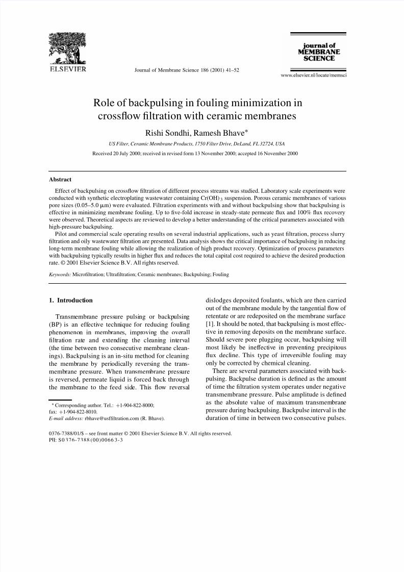
Fig. 1. Schematic representation of membrane cleaning during
backpulsing.
cake on the membrane surface (Fig. 1). It is assumed
that the cake layer is instantly lifted and swept into the
retentate flow [12]. Thus, only particle fouling on the
membrane surface (external fouling) is considered and
internal pore plugging effects are assumed to be mini-mal [12,13]. If the above assumption is valid, then for
complete membrane cleaning, the pore-blocking and
cake-forming particles should be pushed back into
the crossflow and swept away into the retentate flow.
The apparent distance traveled by the solvent
molecule during pulsing should be greater than the
apparent pore length. Then the membrane cleaning
time, t c (the time required to dislodge the particles
from the membrane surface) can be defined as the
ratio of distance traveled by the solvent to the solvent
velocity. Considering a limiting case, when the dis-
tance traveled by the solvent is assumed to be equal to
the pore length L, it can be approximated by using the
d’Arcy’s permeability model, assuming a tortuosity
factor of 2.5 [14,15]
L = 15(εRmr
2) (1)
where µ is the membrane porosity, Rm the mem-
brane resistance and r the pore radius. The particle
velocity is governed by hindered transport in the
narrow pore. However, when the particle size approx-
imates the pore size, the average particle velocity is
equal to the average solvent velocity. This is true for
ceramic membranes as the individual ceramic parti-
cles are dense. The porosity is created by interstitialspace between the solid particles. Assuming the pores
to be interstices between close-packed spheres, the
flow through the membrane can be described by the
Kozeny–Carman equation [16]
J =ε3 P
KH mµS 2i (1 − ε)2
(2)
where J is the permeate flux, P the applied trans-
membrane pressure (TMP), µ the permeate viscosity, H m the membrane thickness, K the Kozeny–Carman
constant and S i the internal surface area per unit vol-
ume of membrane. For spherical particles and assum-
ing K = 5 [17], the above equation can be written as
J =ε3r2 P
45H mµ(1 − ε)2 (3)
The cleaning time (t c) can now be written as
t c =εRmr
2/5
ε3r2 P/45H mµ(1 − ε)2
= 9µRmH m(1 − ε)2
Pε2 (4)
From the above equation, it can be seen that the
cleaning time is proportional to permeate viscosity,
membrane resistance, membrane thickness and inver-
sely proportional to TMP.
3. Experimental
3.1. Bench-scale system
For laboratory scale studies, Membralox® (USFilter, DeLand, FL) ceramic membranes of various
pore sizes (0.05–5.0m) were used in the filtration
experiments. These tubular membranes were 250 mm
in length with internal diameter of 7 mm. Filtration ex-
periments with synthetic wastewater were performed
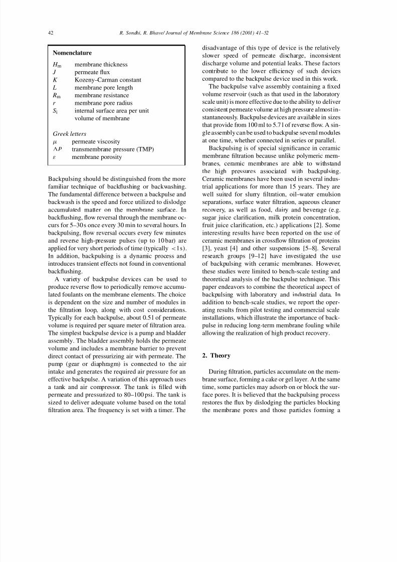
using a bench-top filter unit (US Filter 1T1-70) as
shown in Fig. 2. The unit was equipped with a 12 l
conical bottom feed tank, a 50 psi two-stage centrifu-
gal pump, which feeds a 250 mm membrane housing
connected with a backpulse unit. The unit incorpo-
rated a tubular heat exchanger, a paddlewheel flow
meter with analog display, six valves (V1–V6), and
three pressure gauges (PI, PO, and PP). In filtrationexperiments, the feed solution was pumped to the
filter unit and during forward filtration the pressure
7/18/2019 8_Role of backpulsing in fouling minimization in crossflow filtration with ceramic membranes.pdf
http://slidepdf.com/reader/full/8role-of-backpulsing-in-fouling-minimization-in-crossflow-filtration-with 4/12
44 R. Sondhi, R. Bhave/ Journal of Membrane Science 186 (2001) 41–52
Fig. 2. Ceramic membrane filtration system.
gradient was maintained by adjusting the flow rate
(using valves V1 and V2) of the feed solution.
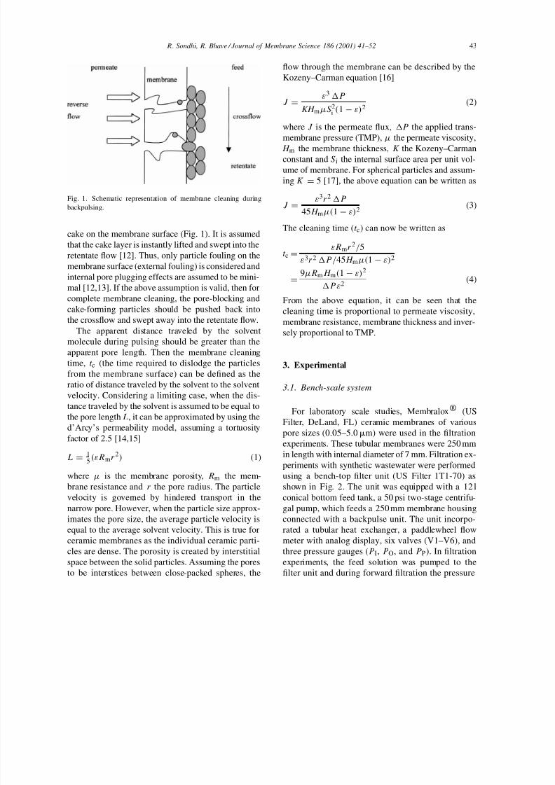
The backpulse unit was attached on the permeate
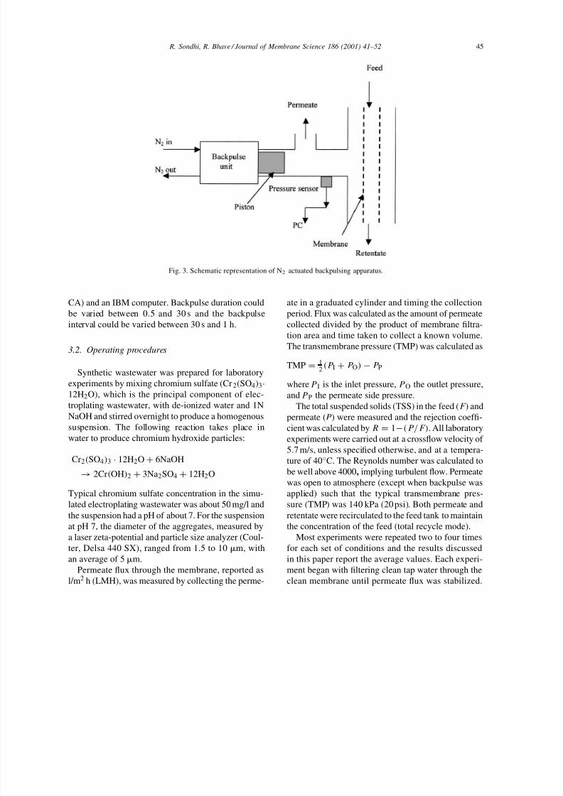
side of the membrane housing. Fig. 3 is the schematic
of the particular backpulse device studied in this
work. During reverse filtration, a timer initiated puls-
ing. A solenoid valve, pressurized with nitrogen gas,
activated the backpulse unit by directing a nitrogen
pulse to the backpulse valve. The backpulse deviceassembly incorporates a known volume permeate
reservoir and a cylindrical piston. When the backpulse
valve is actuated, the piston moves rapidly, displac-
ing permeate and causing a flow reversal through the
membrane for a very short duration. The flow rever-
sal removes adsorbed particles and accumulated cake
from the membrane deposited during filtration. This
very short reverse filtration was followed by a longer
forward filtration period during which permeate was
collected. Permeate side pressure was measured by a
high accuracy sensor (PX 800-100GV, Omega Engi-neering, Stamford, CT) used in conjunction with data
acquisition software (Strawberry Tree, Sunnyvale,
7/18/2019 8_Role of backpulsing in fouling minimization in crossflow filtration with ceramic membranes.pdf
http://slidepdf.com/reader/full/8role-of-backpulsing-in-fouling-minimization-in-crossflow-filtration-with 5/12
R. Sondhi, R. Bhave / Journal of Membrane Science 186 (2001) 41–52 45
Fig. 3. Schematic representation of N2 actuated backpulsing apparatus.
CA) and an IBM computer. Backpulse duration could
be varied between 0.5 and 30 s and the backpulse
interval could be varied between 30 s and 1 h.
3.2. Operating procedures
Synthetic wastewater was prepared for laboratory
experiments by mixing chromium sulfate (Cr2(SO4)3·
12H2O), which is the principal component of elec-
troplating wastewater, with de-ionized water and 1N
NaOH and stirred overnight to produce a homogenoussuspension. The following reaction takes place in
water to produce chromium hydroxide particles:
Cr2(SO4)3 · 12H2O + 6NaOH
→ 2Cr(OH)2 + 3Na2SO4 + 12H2O
Typical chromium sulfate concentration in the simu-
lated electroplating wastewater was about 50 mg/l and
the suspension had a pH of about 7. For the suspension
at pH 7, the diameter of the aggregates, measured by
a laser zeta-potential and particle size analyzer (Coul-
ter, Delsa 440 SX), ranged from 1.5 to 10 m, with
an average of 5m.Permeate flux through the membrane, reported as
l/m2 h (LMH), was measured by collecting the perme-
ate in a graduated cylinder and timing the collection
period. Flux was calculated as the amount of permeate
collected divided by the product of membrane filtra-
tion area and time taken to collect a known volume.
The transmembrane pressure (TMP) was calculated as
TMP = 12(P I + P O)− P P
where PI is the inlet pressure, PO the outlet pressure,
and PP the permeate side pressure.
The total suspended solids (TSS) in the feed (F ) and
permeate (P) were measured and the rejection coeffi-cient was calculated by R = 1−(P/F). All laboratory
experiments were carried out at a crossflow velocity of
5.7 m/s, unless specified otherwise, and at a tempera-
ture of 40◦C. The Reynolds number was calculated to
be well above 4000, implying turbulent flow. Permeate
was open to atmosphere (except when backpulse was
applied) such that the typical transmembrane pres-
sure (TMP) was 140 kPa (20 psi). Both permeate and
retentate were recirculated to the feed tank to maintain
the concentration of the feed (total recycle mode).
Most experiments were repeated two to four times
for each set of conditions and the results discussed
in this paper report the average values. Each experi-ment began with filtering clean tap water through the
clean membrane until permeate flux was stabilized.
7/18/2019 8_Role of backpulsing in fouling minimization in crossflow filtration with ceramic membranes.pdf
http://slidepdf.com/reader/full/8role-of-backpulsing-in-fouling-minimization-in-crossflow-filtration-with 6/12
46 R. Sondhi, R. Bhave/ Journal of Membrane Science 186 (2001) 41–52
Table 1
Summary of typical parameter values for laboratory filtration
experiments
Membrane characteristics
Ceramic membrane tube i.d 7 mm
Tube length 25 cm
Nominal pore size 0.05, 0.2, 0.8m
Porosity 50%Feed conditions of sulfate suspension
Solid concentration 50 mg/l
pH 7
Temperature 40◦C
Typical process parameters
Forward filtration pressure 140 kPa (20 psi)
Backpulse amplitude 170 kPa (25 psi)
Crossflow velocity 5.7 m/s
Backpulse duration 0.5 s
Backpulse interval 30 s
At this point the feed was changed to the synthetic
wastewater. Membranes were reused, and underwent amulti-step cleaning procedure involving 1% (wt./wt.)
HNO3 followed with 2% (wt./wt.) NaOH solutions.
The system was thoroughly rinsed with clean water
prior to the start of a new experiment. The membranes
were stored in dilute NaOCl to prevent bacterial
growth. Typical values of key operating parameters
are given in Table 1.
The objective of pilot testing is to obtain data suit-
able for scale-up. It is, therefore, necessary to operate
the unit for a sufficiently long period to obtain in-
formation on long-term fouling characteristics. Many
industrial applications require continuous filtration at
constant filtrate flow. The transmembrane pressureincreases as the run progresses to maintain constant
flow. For batch processes the filtrate flow is initially
high and decreases with concentration factor. The
industrial examples discussed later in the paper (see
Section 4.3) show filtration performance under both
variable flux and constant flux conditions representa-
tive of batch and continuous processing, respectively.
The backpulse time and duration are set from the
start of the run. The filtration cycle is continued until
the filtrate flow drops substantially below the starting
value, indicating irreversible fouling. At this time,
chemical cleaning is performed to remove foulants
on the membrane. The cleaning interval between twosuccessive filtration cycles is an important design
parameter. The primary purpose for pilot testing is
to establish reproducibility of process flux, cleaning
intervals and to validate the cleaning protocol.
4. Results and discussion
4.1. Laboratory filtration results
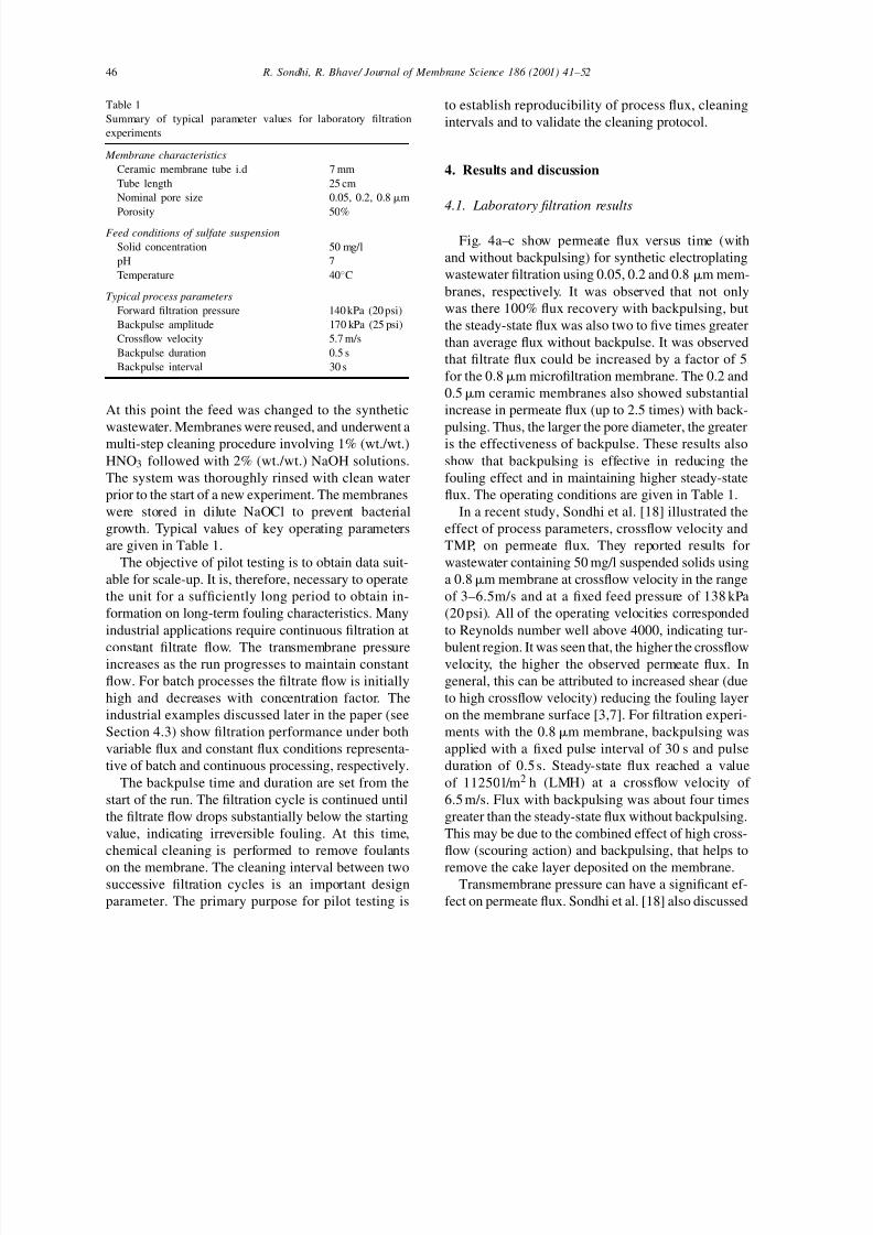
Fig. 4a–c show permeate flux versus time (with
and without backpulsing) for synthetic electroplating
wastewater filtration using 0.05, 0.2 and 0.8 m mem-
branes, respectively. It was observed that not only
was there 100% flux recovery with backpulsing, but
the steady-state flux was also two to five times greater
than average flux without backpulse. It was observed
that filtrate flux could be increased by a factor of 5
for the 0.8m microfiltration membrane. The 0.2 and
0.5m ceramic membranes also showed substantial
increase in permeate flux (up to 2.5 times) with back-
pulsing. Thus, the larger the pore diameter, the greateris the effectiveness of backpulse. These results also
show that backpulsing is effective in reducing the
fouling effect and in maintaining higher steady-state
flux. The operating conditions are given in Table 1.
In a recent study, Sondhi et al. [18] illustrated the
effect of process parameters, crossflow velocity and
TMP, on permeate flux. They reported results for
wastewater containing 50 mg/l suspended solids using
a 0.8m membrane at crossflow velocity in the range
of 3–6.5m/s and at a fixed feed pressure of 138 kPa
(20 psi). All of the operating velocities corresponded
to Reynolds number well above 4000, indicating tur-
bulent region. It was seen that, the higher the crossflowvelocity, the higher the observed permeate flux. In
general, this can be attributed to increased shear (due
to high crossflow velocity) reducing the fouling layer
on the membrane surface [3,7]. For filtration experi-
ments with the 0.8m membrane, backpulsing was
applied with a fixed pulse interval of 30 s and pulse
duration of 0.5 s. Steady-state flux reached a value
of 11250 l/m2 h (LMH) at a crossflow velocity of
6.5 m/s. Flux with backpulsing was about four times
greater than the steady-state flux without backpulsing.
This may be due to the combined effect of high cross-
flow (scouring action) and backpulsing, that helps to
remove the cake layer deposited on the membrane.Transmembrane pressure can have a significant ef-
fect on permeate flux. Sondhi et al. [18] also discussed
7/18/2019 8_Role of backpulsing in fouling minimization in crossflow filtration with ceramic membranes.pdf
http://slidepdf.com/reader/full/8role-of-backpulsing-in-fouling-minimization-in-crossflow-filtration-with 7/12
R. Sondhi, R. Bhave / Journal of Membrane Science 186 (2001) 41–52 47
Fig. 4. ((a)–(c)) Filtration results with synthetic electroplating water
with and without backpulsing for (a) 0.05, (b) 0.2 and (c) 0.8m
membrane.
the effect of TMP on flux during wastewater filtra-
tion with a 0.8m membrane. TMP was in the range
of 100–175 kPa and crossflow velocity was at 5.0 m/s.
Steady-state flux increased with transmembrane pres-
sure. However, the rate of increase decreased at higher
transmembrane pressure of 172 kPa and the flux ap-
peared to level out. This phenomenon could be at-
tributed to the fact that at higher operating pressure,
the effect of fouling is more important as the cake
layer thickness on the membrane increases. Sondhi
et al. [18] reported that when backpulsing was applied,
the steady-state flux reached a maximum of 12,300
LMH at a TMP of 170 kPa, which was about 2.6 times
greater than the nonpulsed steady-state flux at the same
conditions. It should be noted that the high flux val-
ues reported in this study are not indicative of the flux
values achieved in typical wastewater treatment appli-
cations. These values are high due to the dilute nature
of synthetic samples. However, dilute feed systems are
ideally suited for fundamental analysis and modelingof backpulsing.
4.2. Laboratory backpulse results
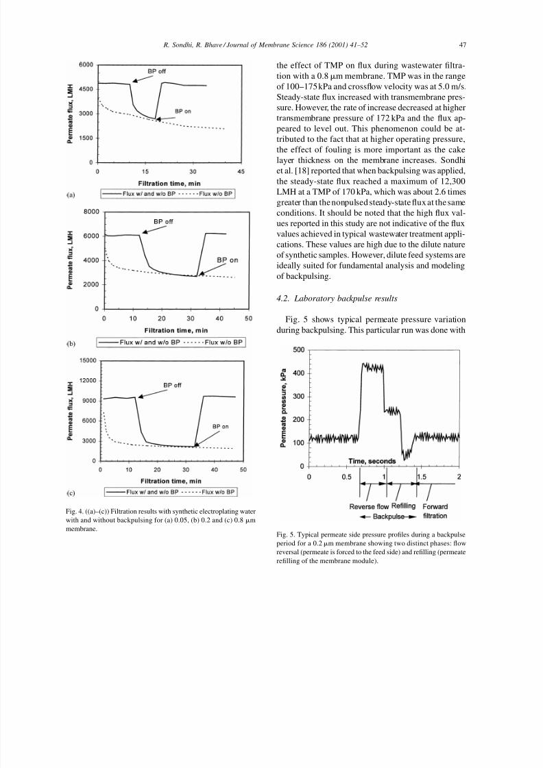
Fig. 5 shows typical permeate pressure variation
during backpulsing. This particular run was done with
Fig. 5. Typical permeate side pressure profiles during a backpulse
period for a 0.2m membrane showing two distinct phases: flow
reversal (permeate is forced to the feed side) and refilling (permeate
refilling of the membrane module).
7/18/2019 8_Role of backpulsing in fouling minimization in crossflow filtration with ceramic membranes.pdf
http://slidepdf.com/reader/full/8role-of-backpulsing-in-fouling-minimization-in-crossflow-filtration-with 8/12
48 R. Sondhi, R. Bhave/ Journal of Membrane Science 186 (2001) 41–52
a 0.2m membrane, pulse duration of 0.5 s, and pulse
interval of 30 s. It can be seen from the pressure versus
time profile that the backpulse process consists of two
distinct phases. In the first phase, pressure is applied
on the piston which forces permeate back through the
membrane. This represents the steep rise in the perme-
ate side pressure as shown in the curve. It is believed
that reverse flow and hence, membrane cleaning takes
place during this time. In the second phase, the piston
remains at the extended position for some time to al-
low the cylinder to refill with permeate as the piston
returns to the original position before the next pulse
(refilling time). The backpulse cycle is followed by
a longer forward filtration cycle. Levesley and Hoare
[10] observed similar permeate side pressure trends
during ceramic membrane filtration of yeast suspen-
sion with backpulsing.
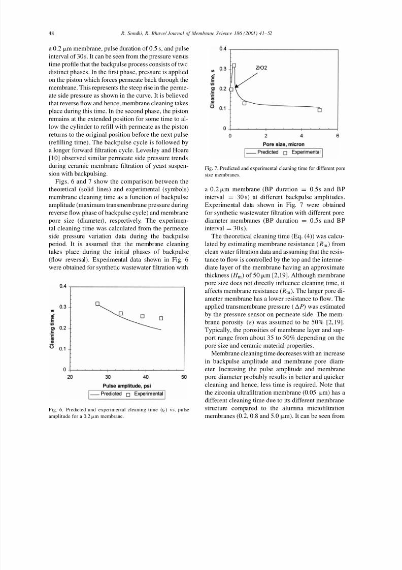
Figs. 6 and 7 show the comparison between the
theoretical (solid lines) and experimental (symbols)
membrane cleaning time as a function of backpulseamplitude (maximum transmembrane pressure during
reverse flow phase of backpulse cycle) and membrane
pore size (diameter), respectively. The experimen-
tal cleaning time was calculated from the permeate
side pressure variation data during the backpulse
period. It is assumed that the membrane cleaning
takes place during the initial phases of backpulse
(flow reversal). Experimental data shown in Fig. 6
were obtained for synthetic wastewater filtration with
Fig. 6. Predicted and experimental cleaning time (t c) vs. pulse
amplitude for a 0.2m membrane.
Fig. 7. Predicted and experimental cleaning time for different pore
size membranes.
a 0.2m membrane (BP duration = 0.5s and BP
interval =
30 s) at different backpulse amplitudes.Experimental data shown in Fig. 7 were obtained
for synthetic wastewater filtration with different pore
diameter membranes (BP duration = 0.5s and BP
interval = 30 s).
The theoretical cleaning time (Eq. (4)) was calcu-
lated by estimating membrane resistance ( Rm) from
clean water filtration data and assuming that the resis-
tance to flow is controlled by the top and the interme-
diate layer of the membrane having an approximate
thickness ( H m) of 50m [2,19]. Although membrane
pore size does not directly influence cleaning time, it
affects membrane resistance ( Rm). The larger pore di-
ameter membrane has a lower resistance to flow. Theapplied transmembrane pressure (P) was estimated
by the pressure sensor on permeate side. The mem-
brane porosity (ε) was assumed to be 50% [2,19].
Typically, the porosities of membrane layer and sup-
port range from about 35 to 50% depending on the
pore size and ceramic material properties.
Membrane cleaning time decreases with an increase
in backpulse amplitude and membrane pore diam-
eter. Increasing the pulse amplitude and membrane
pore diameter probably results in better and quicker
cleaning and hence, less time is required. Note that
the zirconia ultrafiltration membrane (0.05 m) has a
different cleaning time due to its different membranestructure compared to the alumina microfiltration
membranes (0.2, 0.8 and 5.0 m). It can be seen from
7/18/2019 8_Role of backpulsing in fouling minimization in crossflow filtration with ceramic membranes.pdf
http://slidepdf.com/reader/full/8role-of-backpulsing-in-fouling-minimization-in-crossflow-filtration-with 9/12
R. Sondhi, R. Bhave / Journal of Membrane Science 186 (2001) 41–52 49
Figs. 6 and 7 that, there is a close agreement between
the theoretical and experimental cleaning times for
different backpulse amplitudes and membrane pore
sizes. It can be inferred that the model is applicable
to both ultrafiltration and microfiltration processes.
The operating conditions are given in Table 1. A
minimum pulse amplitude of about 170 kPa (25 psi)
was necessary for effective membrane cleaning and
to obtain an increase in flux. It was observed that for
pulse amplitude <170kPa, the force acting on the
piston was too small to initiate backpulsing. Rodgers
and Sparks [20] also reported that for short pulses
with low amplitude, significant flow reversal was
not observed during ultrafiltration of totally retained
solutes using transmembrane pressure pulsing.
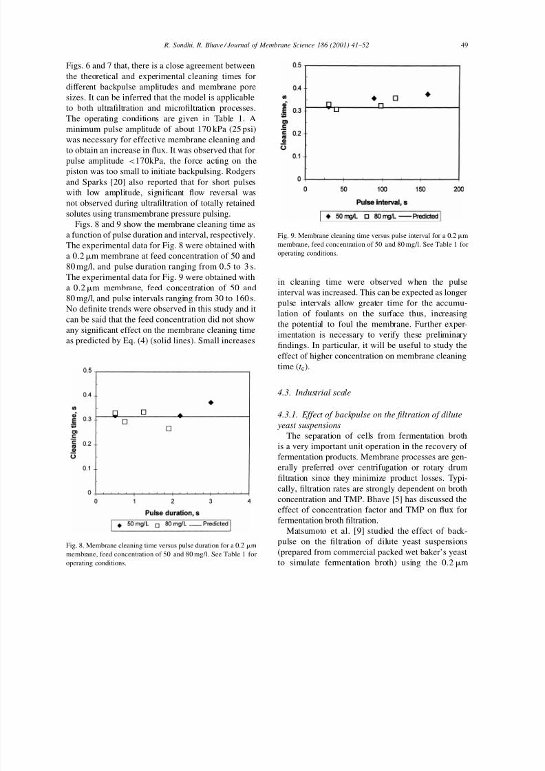
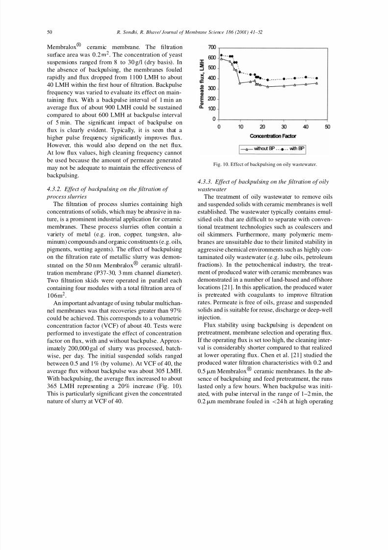
Figs. 8 and 9 show the membrane cleaning time as
a function of pulse duration and interval, respectively.
The experimental data for Fig. 8 were obtained with
a 0.2m membrane at feed concentration of 50 and
80 mg/l, and pulse duration ranging from 0.5 to 3 s.The experimental data for Fig. 9 were obtained with
a 0.2m membrane, feed concentration of 50 and
80 mg/l, and pulse intervals ranging from 30 to 160 s.
No definite trends were observed in this study and it
can be said that the feed concentration did not show
any significant effect on the membrane cleaning time
as predicted by Eq. (4) (solid lines). Small increases
Fig. 8. Membrane cleaning time versus pulse duration for a 0.2 m
membrane, feed concentration of 50 and 80 mg/l. See Table 1 for
operating conditions.
Fig. 9. Membrane cleaning time versus pulse interval for a 0.2 m
membrane, feed concentration of 50 and 80 mg/l. See Table 1 for
operating conditions.
in cleaning time were observed when the pulse
interval was increased. This can be expected as longer
pulse intervals allow greater time for the accumu-
lation of foulants on the surface thus, increasing
the potential to foul the membrane. Further exper-
imentation is necessary to verify these preliminary
findings. In particular, it will be useful to study the
effect of higher concentration on membrane cleaning
time (t c).
4.3. Industrial scale
4.3.1. Effect of backpulse on the filtration of dilute
yeast suspensions
The separation of cells from fermentation broth
is a very important unit operation in the recovery of
fermentation products. Membrane processes are gen-
erally preferred over centrifugation or rotary drum
filtration since they minimize product losses. Typi-
cally, filtration rates are strongly dependent on broth
concentration and TMP. Bhave [5] has discussed the
effect of concentration factor and TMP on flux for
fermentation broth filtration.
Matsumoto et al. [9] studied the effect of back-
pulse on the filtration of dilute yeast suspensions(prepared from commercial packed wet baker’s yeast
to simulate fermentation broth) using the 0.2m
7/18/2019 8_Role of backpulsing in fouling minimization in crossflow filtration with ceramic membranes.pdf
http://slidepdf.com/reader/full/8role-of-backpulsing-in-fouling-minimization-in-crossflow-filtration-with 10/12
50 R. Sondhi, R. Bhave/ Journal of Membrane Science 186 (2001) 41–52
Membralox® ceramic membrane. The filtration
surface area was 0.2 m2. The concentration of yeast
suspensions ranged from 8 to 30 g/l (dry basis). In
the absence of backpulsing, the membranes fouled
rapidly and flux dropped from 1100 LMH to about
40 LMH within the first hour of filtration. Backpulse
frequency was varied to evaluate its effect on main-
taining flux. With a backpulse interval of 1 min an
average flux of about 900 LMH could be sustained
compared to about 600 LMH at backpulse interval
of 5 min. The significant impact of backpulse on
flux is clearly evident. Typically, it is seen that a
higher pulse frequency significantly improves flux.
However, this would also depend on the net flux.
At low flux values, high cleaning frequency cannot
be used because the amount of permeate generated
may not be adequate to maintain the effectiveness of
backpulsing.
4.3.2. Effect of backpulsing on the filtration of
process slurries
The filtration of process slurries containing high
concentrations of solids, which may be abrasive in na-
ture, is a prominent industrial application for ceramic
membranes. These process slurries often contain a
variety of metal (e.g. iron, copper, tungsten, alu-
minum) compounds and organic constituents (e.g. oils,
pigments, wetting agents). The effect of backpulsing
on the filtration rate of metallic slurry was demon-
strated on the 50 nm Membralox® ceramic ultrafil-
tration membrane (P37-30, 3 mm channel diameter).
Two filtration skids were operated in parallel each
containing four modules with a total filtration area of 106m2.
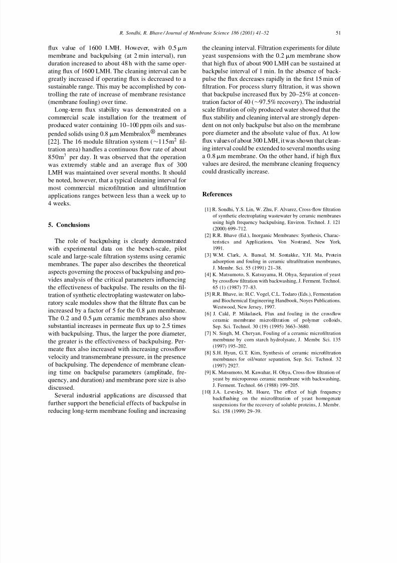
An important advantage of using tubular multichan-
nel membranes was that recoveries greater than 97%
could be achieved. This corresponds to a volumetric
concentration factor (VCF) of about 40. Tests were
performed to investigate the effect of concentration
factor on flux, with and without backpulse. Approx-
imately 200,000 gal of slurry was processed, batch-
wise, per day. The initial suspended solids ranged
between 0.5 and 1% (by volume). At VCF of 40, the
average flux without backpulse was about 305 LMH.
With backpulsing, the average flux increased to about
365 LMH representing a 20% increase (Fig. 10).This is particularly significant given the concentrated
nature of slurry at VCF of 40.
Fig. 10. Effect of backpulsing on oily wastewater.
4.3.3. Effect of backpulsing on the filtration of oily
wastewater
The treatment of oily wastewater to remove oils
and suspended solids with ceramic membranes is well
established. The wastewater typically contains emul-
sified oils that are difficult to separate with conven-
tional treatment technologies such as coalescers and
oil skimmers. Furthermore, many polymeric mem-
branes are unsuitable due to their limited stability in
aggressive chemical environments such as highly con-
taminated oily wastewater (e.g. lube oils, petroleum
fractions). In the petrochemical industry, the treat-
ment of produced water with ceramic membranes was
demonstrated in a number of land-based and offshore
locations [21]. In this application, the produced wateris pretreated with coagulants to improve filtration
rates. Permeate is free of oils, grease and suspended
solids and is suitable for reuse, discharge or deep-well
injection.
Flux stability using backpulsing is dependent on
pretreatment, membrane selection and operating flux.
If the operating flux is set too high, the cleaning inter-
val is considerably shorter compared to that realized
at lower operating flux. Chen et al. [21] studied the
produced water filtration characteristics with 0.2 and
0.5m Membralox® ceramic membranes. In the ab-
sence of backpulsing and feed pretreatment, the runs
lasted only a few hours. When backpulse was initi-ated, with pulse interval in the range of 1–2 min, the
0.2m membrane fouled in <24 h at high operating
7/18/2019 8_Role of backpulsing in fouling minimization in crossflow filtration with ceramic membranes.pdf
http://slidepdf.com/reader/full/8role-of-backpulsing-in-fouling-minimization-in-crossflow-filtration-with 11/12
R. Sondhi, R. Bhave / Journal of Membrane Science 186 (2001) 41–52 51
flux value of 1600 LMH. However, with 0.5m
membrane and backpulsing (at 2 min interval), run
duration increased to about 48 h with the same oper-
ating flux of 1600 LMH. The cleaning interval can be
greatly increased if operating flux is decreased to a
sustainable range. This may be accomplished by con-
trolling the rate of increase of membrane resistance
(membrane fouling) over time.
Long-term flux stability was demonstrated on a
commercial scale installation for the treatment of
produced water containing 10–100 ppm oils and sus-
pended solids using 0.8m Membralox® membranes
[22]. The 16 module filtration system (∼115m2 fil-
tration area) handles a continuous flow rate of about
850m3 per day. It was observed that the operation
was extremely stable and an average flux of 300
LMH was maintained over several months. It should
be noted, however, that a typical cleaning interval for
most commercial microfiltration and ultrafiltration
applications ranges between less than a week up to4 weeks.
5. Conclusions
The role of backpulsing is clearly demonstrated
with experimental data on the bench-scale, pilot
scale and large-scale filtration systems using ceramic
membranes. The paper also describes the theoretical
aspects governing the process of backpulsing and pro-
vides analysis of the critical parameters influencing
the effectiveness of backpulse. The results on the fil-
tration of synthetic electroplating wastewater on labo-ratory scale modules show that the filtrate flux can be
increased by a factor of 5 for the 0.8 m membrane.
The 0.2 and 0.5m ceramic membranes also show
substantial increases in permeate flux up to 2.5 times
with backpulsing. Thus, the larger the pore diameter,
the greater is the effectiveness of backpulsing. Per-
meate flux also increased with increasing crossflow
velocity and transmembrane pressure, in the presence
of backpulsing. The dependence of membrane clean-
ing time on backpulse parameters (amplitude, fre-
quency, and duration) and membrane pore size is also
discussed.
Several industrial applications are discussed thatfurther support the beneficial effects of backpulse in
reducing long-term membrane fouling and increasing
the cleaning interval. Filtration experiments for dilute
yeast suspensions with the 0.2m membrane show
that high flux of about 900 LMH can be sustained at
backpulse interval of 1 min. In the absence of back-
pulse the flux decreases rapidly in the first 15 min of
filtration. For process slurry filtration, it was shown
that backpulse increased flux by 20–25% at concen-
tration factor of 40 (∼97.5% recovery). The industrial
scale filtration of oily produced water showed that the
flux stability and cleaning interval are strongly depen-
dent on not only backpulse but also on the membrane
pore diameter and the absolute value of flux. At low
flux values of about 300 LMH, it was shown that clean-
ing interval could be extended to several months using
a 0.8m membrane. On the other hand, if high flux
values are desired, the membrane cleaning frequency
could drastically increase.
References
[1] R. Sondhi, Y.S. Lin, W. Zhu, F. Alvarez, Cross-flow filtration
of synthetic electroplating wastewater by ceramic membranes
using high frequency backpulsing, Environ. Technol. J. 121
(2000) 699–712.
[2] R.R. Bhave (Ed.), Inorganic Membranes: Synthesis, Charac-
teristics and Applications, Von Nostrand, New York,
1991.
[3] W.M. Clark, A. Bansal, M. Sontakke, Y.H. Ma, Protein
adsorption and fouling in ceramic ultrafiltration membranes,
J. Membr. Sci. 55 (1991) 21–38.
[4] K. Matsumoto, S. Katsuyama, H. Ohya, Separation of yeast
by crossflow filtration with backwashing, J. Ferment. Technol.
65 (1) (1987) 77–83.
[5] R.R. Bhave, in: H.C. Vogel, C.L. Todaro (Eds.), Fermentationand Biochemical Engineering Handbook, Noyes Publications,
Westwood, New Jersey, 1997.
[6] J. Cakl, P. Mikulasek, Flux and fouling in the crossflow
ceramic membrane microfiltration of polymer colloids,
Sep. Sci. Technol. 30 (19) (1995) 3663–3680.
[7] N. Singh, M. Cheryan, Fouling of a ceramic microfiltration
membrane by corn starch hydrolysate, J. Membr. Sci. 135
(1997) 195–202.
[8] S.H. Hyun, G.T. Kim, Synthesis of ceramic microfiltration
membranes for oil/water separation, Sep. Sci. Technol. 32
(1997) 2927.
[9] K. Matsumoto, M. Kawahar, H. Ohya, Cross-flow filtration of
yeast by microporous ceramic membrane with backwashing,
J. Ferment. Technol. 66 (1988) 199–205.
[10] J.A. Levesley, M. Hoare, The effect of high frequencybackflushing on the microfiltration of yeast homogenate
suspensions for the recovery of soluble proteins, J. Membr.
Sci. 158 (1999) 29–39.
7/18/2019 8_Role of backpulsing in fouling minimization in crossflow filtration with ceramic membranes.pdf
http://slidepdf.com/reader/full/8role-of-backpulsing-in-fouling-minimization-in-crossflow-filtration-with 12/12
52 R. Sondhi, R. Bhave/ Journal of Membrane Science 186 (2001) 41–52
[11] S. Vigneswaran, S. Boonthanon, H. Prasanthi, Filter backwash
recycling using crossflow microfiltration, Desalination 106
(1996) 31–38.
[12] J. Cakl, I. Bauer, R. Dolecek, P. Mkulasek, Effects of back-
flushing conditions on permeate flux in membrane crossflow
microfiltration of oil emulsion, Desalination 127 (2000)
189–198.
[13] W.D. Mores, C.N. Bowman, R.H. Davis, Theoretical and
experimental flux maximization by optimization of back-pulsing, J. Membr. Sci. 165 (2000) 225–236.
[14] C. Wilharm, V.G.J. Rodgers, Significance of duration and
amplitude in transmembrane pressure pulsed ultrafiltration
of binary proteins, J. Membr. Sci. 121 (1996) 217–228.
[15] A.F.M. Leenaars, A.J. Burggraaf, The preparation and
characterization of alumina membranes with ultra-fine pores:
Part 3. The permeability for pure liquids, J. Membr. Sci. 24
(1985) 245–260.
[16] A.J. Burggraaf, L. Cot, Fundamentals of Inorganic Mem-
branes Science and Technology, Elsevier, Amsterdam, 1996.
[17] L.J. Zemen, A.L. Zydney, Microfiltration and Ultrafiltration,
Marcel Dekker, New York, 1996.
[18] R. Sondhi, Y.S. Lin, F. Alvarez, Crossflow filtration of
chromium hydroxide suspension by ceramic membranes:
fouling and its minimization by backpulsing, J. Membr. Sci.
174 (2000) 111–122.
[19] H.P. Hsieh, R.R. Bhave, H.L. Fleming, Microporous alumina
membranes, J. Membr. Sci. 39 (1988) 221–241.
[20] V.G.J. Rodgers, R.E. Sparks, Reduction of membrane foulingin the ultrafiltration of binary protein mixture, AIChE J. 37
(1991) 1517–1528.
[21] A.S.C. Chen, J.T. Flynn, R.G. Cook, A.L. Casaday, Removal
of oil, grease, and suspended solids from produced water
with ceramic crossflow microfiltration, SPE Prod. Eng.
(1991) 131–136.
[22] J.L. Filson, R.R. Bhave, Cross-flow filtration of produced
water with ceramic microfilters, Adv. Filtrat. Sep. Technol.
7 (1993) Paper D5.1.