Embed Size (px)
Citation preview

7/26/2019 8IMP
http://slidepdf.com/reader/full/8imp 1/15
INTERNATIONAL JOURNAL OF ENERGY RESEARCH
Int. J . Energy Res., 22, 317— 331 (1998)
EXPERIMENTAL AND SIMULATION ANALYSISOF THE TRANSIENT OPERATION OF A TURBOCHARGED
MULTI-CYLINDER IDI DIESEL ENGINE
C. D. RAKOPOULOS*, E. G. GIAKOUMIS AND D. T. HOUNTALAS
Internal Combustion Engines Laboratory, Thermal Engineering Section, Mechanical Engineering Department, National Technical University
of Athens, 42 Patission Str., Athens 10682, Greece
SUMMARY
An experimental and theoretical analysis is carried out to study the response of a multi-cylinder, turbocharged, IDI(indirect injection) compression ignition engine, under transient operating conditions. To this aim, a comprehensivedigital computer model is developed which solves the governing differential equations individually for each cylinder,providing thus increased accuracy over previous ‘single-cylinder’ simulations. Special attention has been paid fordiversifying the transient operation from the steady-state one, providing improved or even new relations concerningcombustion, heat transfer to the cylinder walls, friction, turbocharger and aftercooler operation, and dynamic analysis forthe transient case. An extended steady state and transient experimental work is conducted on a specially developedengine test bed configuration, located at the authors’ laboratory, which is connected to a high-speed data acquisition andprocessing system. The steady-state measurements are used for the calibration of the individual submodel constants. Thetransient investigation includes both speed and load changes operating schedules. During each transient test four majormeasurements are continuously made, i.e. engine speed, fuel pump rack position, main chamber pressure and turbochar-ger compressor boost pressure. The hydraulic brake coupled to the engine possesses a high mass moment of inertia andlong nonlinear load-change times, which together with the indirect injection nature of the engine are importantchallenges for the simulation code. Explicit multiple diagrams are given to describe the engine and turbocharger transientbehaviour including smoke predictions. The agreement between experimental and predicted responses is satisfactory, forall the cases examined, proving the validity of the simulation process, while providing useful information for the engineresponse under various transient operations. 1998 John Wiley & Sons, Ltd.
Int. J . Energy Res., 22, 317— 331 (1998)
No. of Figures: 7 No. of Tables: 1 No. of References: 30KEY WORDS turbocharged diesel engine; transient operation; experiments; simulation
1. INTRODUCTION
The turbocharged compression ignition engine is nowadays the most preferred prime mover in medium and
medium-large units applications (electrical generation, ship propulsion, truck driving, land traction), due toits reliability and high availability combined with an excellent thermal efficiency. Nonetheless, its transient
operation is often combined with off-design (e.g. turbocharger lag) and consequently non-optimum perfor-
mance, pointing out the significance of proper interconnection between engine, governor, fuel pump,
turbocharger and load. Towards this objective, diesel engine simulation has contributed enormously in the
last 20 yr.
* Correspondence to: C. D. Rakopoulos, Internal Combustion Engines Laboratory, Thermal Engineering Section, Mechanical
Engineering Department, National Technical University of Athens, 42 Patission Str., Athens 10682, Greece.
CCC 0363-907X/98/040317— 15$17.50 Received 10 March 1997 1998 John Wiley & Sons, Ltd. Accepted 20 May 1997

7/26/2019 8IMP
http://slidepdf.com/reader/full/8imp 2/15
Transient diesel engine modelling extends from quasi-linear codes (Ledger and Walmsley, 1971;
Winterbone et al., 1976; Rackmil and Blumberg, 1989), where use is made of experimental data at
steady-state conditions together with dynamic equations for the engine, turbocharger and governor, to more
advanced works, where the simulation is based on a detailed thermodynamic (per degree crank angle)
analysis (Watson and Marzouk, 1977; Watson, 1981; Zellbeck and Woschni, 1983; Horlock and Winterbone,
1986; Qiao et al., 1992; Bazari, 1994). Here, the governor is modelled using a second-order differential
equation, while each cylinder in a multi-cylinder engine is assumed to behave in exactly the same way.
Furthermore, the fuel pump is modelled using steady-state characteristics for the injected fuel quantity, while
the combustion, heat transfer, friction and turbocharger modellings follow essentially the steady-state
operation.
It is well understood today (Murayama et al., 1980; Winterbone and Tennant, 1981; Horlock and
Winterbone, 1986) that the transient response is characterized by serious off-design and off-steady-
state operations which the conventional modelling cannot predict reliably, being based on a steady-
state philosophy. Moreover, during the last years, a great effort has been made for correct transient cycles
analysis (Pilley et al., 1989; Jiang and Van Gerpen, 1992) as well as pollutants emissions measurements
during the transient operation (Hong et al., 1987; Pilley et al., 1989; Arcoumanis et al., 1994), since it iswell established that the instationary operation contributes much more to the total amount of emissions
than the stationary one. Reliable study of the pollutants emissions during the transient operation via the
use of multi-zone models (Bazari, 1994) is thus an important objective, whose accomplishment is limited
at the moment by the big computational time required for the analysis of hundreds of cycles, in addition to
the fact that the transient operation has not yet been accurately analysed and diversified from the
steady-state one with complete account for its unsteady nature characteristics. Simulation constants of the
individual submodels behave differently during the transient operation and care has to be taken for proper
modelling.
The present work describes the development of a transient diesel engine simulation code, which incorpor-
ates some important novel features to account for the peculiarities of the transient operations. To this aim,
improved or even new relations concerning (indirect) fuel injection, combustion, dynamic analysis, heat
transfer to the cylinder walls (Rakopoulos and Giakoumis, 1997b; Rakopoulos et al., 1997a), friction
modelling, and turbocharger and aftercooler operation during the transient response have been developed,
which contribute to a more in-depth modelling. Moreover, a multi-cylinder engine model is incorporated, i.e.
one which solves the corresponding differential equations individually for each cylinder, providing a more
detailed simulation of the transient processes; the latter issue is important since during a transient event
considerable differentiations in fuelling from cylinder to cylinder inside the same cycle are observed,
particularly during the first cycles.
The present experimental investigation is carried out on a six-cylinder, IDI, turbocharged and
aftercooled, medium-high-speed diesel engine of marine duty coupled to a hydraulic brake, located at
the authors’ laboratory. A high-speed data acquisition system was set up for measuring engine and
turbocharger variables performance under both steady state and transient operations. An extended
series of experiments were conducted, with engine operations covering both speed and load changesoperating schedules; the transient behaviour of the particular engine test bed was revealed via multiple
diagrams.
The engine in hand possesses a high moment of inertia which leads to low soot emissions under any load
change. On the other hand, emissions of high amounts of soot are experienced when a speed change is
initiated under any constant load. The transient behaviour of the engine was predicted adequately by the
developed code in spite of the long nonlinear brake loading times and the indirect injection nature of the
engine. This code has already been used for extensive parametric studies on naturally aspirated diesel engines
of the IDI (Rakopoulos and Giakoumis, 1997b; Rakopoulos et al., 1997a) or the DI (Rakopoulos et al.,
1997b) type.
318 C. D. RAKOPOULOS, E. G. GIAKOUMIS AND D. T. HOUNTALAS
Int. J. Energy Res., 22 , 317— 331 (1998) 1998 John Wiley & Sons, Ltd.

7/26/2019 8IMP
http://slidepdf.com/reader/full/8imp 3/15
2. SIMULATION ANALYSIS
The thermodynamic model, developed for the simulation of the turbocharged IDI diesel engine operation, is
characterized by a spatial uniformity of pressure, temperature and composition in the two combustion
chambers (main and prechamber) at each instant of time (Benson and Whitehouse, 1979; Heywood, 1988;Horlock and Winterbone, 1986). Details about the governing equations concerning the indirect fuel injection,
combustion, and heat transfer to the cylinder walls can be found in Kouremenos et al. (1990), Rakopoulos
and Mavropoulos (1996), Rakopoulos and Giakoumis (1997a— c) and Rakopoulos et al. (1997a), where the
proposed necessary modifications for the better simulation of transient operation are cited. In the following
subsections some new aspects of the simulation code are analysed.
2.1. Friction modelling
For the calculation of friction inside the cylinder the method proposed by Rezeka and Henein (1984)
is adopted, which describes the non-steady profile of friction torque during each cycle. In this method
the total amount of friction is divided into six parts; three of them are concerned with the cylinder
movement, i.e.
¹
"c
[(rR
) (p#p
)w]D(n
#0)4n
)r R
(1a)
for the ring viscous lubrication,
¹
"cDn
w(p
#p
)(1!sin )r R
(1b)
for the ring mixed lubrication, and
¹
"c
rR
h DMrR
(1c)
for the piston skirt losses.On the other hand, the remaining three parts concerned with the crankshaft are:
¹
"c
n
NrR
(1d)
for the valve train,
¹
"c (1e)
for the auxiliaries, and
¹
"c
D
4 r
pcos (1f)
for the loaded bearings.
In the above relations R
"sin# sin cos/ 1! sin is the instantaneous piston velocity
(Taylor, 1985), r the crank radius, D the cylinder bore, n
and n
the number of compression and oil rings,
respectively, w the ring width, p the elastic pressure of the rings, p
the instantaneous main chamber pressure,
M the length of the piston skirt, n
the number of valves, N the valve spring force, r
the radius of the journal
bearing, h the thickness of the oil film between piston skirt and cylinder liner and its viscocity. The
coefficients c
—c
are derived through calibration with experimental data. The total friction torque at each
°CA (degree crank angle) is the sum of the above six terms. Figure 1 shows the variation of each friction term,
as well as the total one, during one cycle, for the maximum speed— full load operation of the engine in hand.
The basic engine data are given in Table 1.
TURBOCHARGED MULTI-CYLINDER IDI DIESEL ENGINE 319
1998 John Wiley & Sons, Ltd. Int. J. Energy Res., 22 , 317— 331 (1998)

7/26/2019 8IMP
http://slidepdf.com/reader/full/8imp 4/15
Figure 1. Variation of friction torque terms during a cycle, for engine maximum speed— full load operation
Table 1. Basic data for engine, turbocharger, dynamometer and data logging system
MWM TbRHS 518SIn-line, 6-cyl., 4-stroke, compression ignition, IDI,
Engine model and type turbocharged, aftercooled, marine duty
Speed range 1000— 1500 rpmBore/stroke 140 mm/180 mmCompression ratio 17)7Maximum power 320 HP (236kW) @ 1500 rpmMaximum torque 1520 Nm @ 1250 rpmIntake valve opening/closure 51°CA before TDC/60°CA after BDCExhaust valve opening/closure 64°CA before BDC/47°CA after TDCFuel pump Bosch PE-P series, in-line, 6-cylinder with mechanical
governor Bosch RSUV 300/900Total moment of inertia 15)60 kgm
(engine, flywheel and brake)Brake model and type Schenck U1-40, hydraulic brakeTurbocharger model and type KKK M4B 754/345
Single-stage, centrifugal compressor,Single-stage, twin entry, axial turbine
Turbocharger moment of inertia 7)510 kg m
Data logging system Two 12-bit, 8-channel ADCs, 100 kHz max.sampling rate, installed on IBM compatible PCs
According to Winterbone and Tennant (1981) and Horlock and Winterbone (1986), rapid changes in
loading lead to instantaneous, though considerable, deflections of the crankshaft due to great accelerations,
resulting in an increase of mechanical friction. The following correlation is thus developed (Rakopoulos and
Giakoumis, 1997b; Rakopoulos et al., 1997a) for the transient case:
(¹
)
"(¹
)
[1#c/
] (2)
320 C. D. RAKOPOULOS, E. G. GIAKOUMIS AND D. T. HOUNTALAS
Int. J. Energy Res., 22 , 317— 331 (1998) 1998 John Wiley & Sons, Ltd.

7/26/2019 8IMP
http://slidepdf.com/reader/full/8imp 5/15
where (¹
)
is the steady-state value for the instantaneous total friction torque according to the model of
Rezeka and Henein (1984), (¹
)
is the corresponding instantaneous value during the transient event
according to the current angular acceleration , and the constant c
is found to have a value of 0 )4 for best
matching with the experimental data.
2.2. Turbocharger and aftercooler operation
The simulation of the turbocharger (T/C) is accomplished by using the manufacturer’s data at steady-state
conditions. Two improvements are proposed for the transient case:
(a) For the instantaneous charge air temperature ¹
after the aftercooler (a/c) an hysterysis equation is
applied,
¹
"¹
#(¹
!¹
) (1!e) (3)
where ¹
is the initial charge air temperature at the beginning of the transient response, ¹
" f (
) the
corresponding charge air steady-state temperature according to the current aftercooler effectiveness
,
and c
a constant incorporating the aftercooler thermal inertia. The
for the present engine was foundto be best correlated with the brake mean effective pressure (bmep), due to the fact of increasing cooling
water flow rates with increasing engine load; a second-order correlation was adopted, i.e.
"a
#a
(bmep)#a
(bmep).
(b) During the transient turbocharger operation, it is usually assumed that the compressor characteristics
map still holds true. This is in general not exactly correct, since the map has been drawn for steady-stateoperations. The following correction is proposed for the transient case:
r
"(r
) 1!c
(
)
(4)
where r
is the instantaneous real transient compressor pressure ratio, (r
)
the corresponding steady-state
ratio read directly from the compressor map with the current values of turbocharger speed and mass flowrate,
the instantaneous turbocharger angular acceleration and (
)
the (imaginary) maximum one
resulting after a change in the engine state from the no load-idle speed to the full load-maximum speed
operation during one cycle. The (
)
term is used so that the c
coefficient is made dimensionless.
Detailed experimental work is needed for the evaluation of the appropriate c
value, which for the present
study was found to be 1)0 for optimum matching between experimental and theoretical transient turbo-
charger responses.
2.3. Dynamic analysis
If G
represents the total moment of inertia (engine, flywheel and load), then the conservation of energy
principle applied to the total system (Watson and Marzouk, 1977; Rakopoulos and Giakoumis, 1997b;
Rakopoulos et al., 1997a) reads
¹
(, )!¹
()!¹
(, )"G
(d/dt) (5)
Here, ¹
(, ) stands for the instantaneous value of the engine torque; this is the sum of the gas and the
inertia forces torque, with the complex movement of the rod also taken into consideration (Rakopoulos et al.,
1997a). In equation (5), the load torque for hydraulic brake is ¹
()"k, while ¹
(, ) is found from
equation (2).
For the turbocharger the dynamic equation is, accordingly,
¼Q
!¼Q"G
d
dt (6)
TURBOCHARGED MULTI-CYLINDER IDI DIESEL ENGINE 321
1998 John Wiley & Sons, Ltd. Int. J. Energy Res., 22 , 317— 331 (1998)
7/26/2019 8IMP
http://slidepdf.com/reader/full/8imp 6/15
where ¼Q
and ¼Q
are the instantaneous values for the compressor and turbine power, respectively, as
exposed by Watson and Janota (1982) and Heywood (1988), while
is the turbocharger mechanical
efficiency which is mainly a function of its speed.
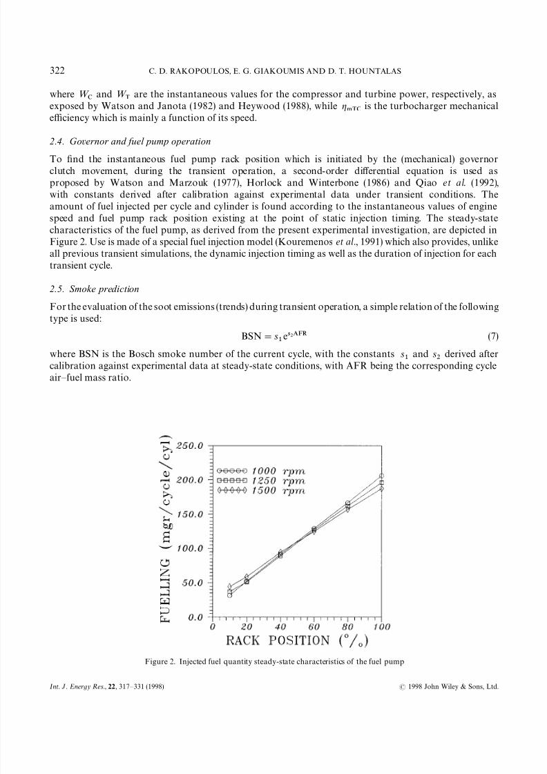
2.4. Governor and fuel pump operation
To find the instantaneous fuel pump rack position which is initiated by the (mechanical) governor
clutch movement, during the transient operation, a second-order differential equation is used as
proposed by Watson and Marzouk (1977), Horlock and Winterbone (1986) and Qiao et al. (1992),
with constants derived after calibration against experimental data under transient conditions. The
amount of fuel injected per cycle and cylinder is found according to the instantaneous values of engine
speed and fuel pump rack position existing at the point of static injection timing. The steady-state
characteristics of the fuel pump, as derived from the present experimental investigation, are depicted in
Figure 2. Use is made of a special fuel injection model (Kouremenos et al., 1991) which also provides, unlike
all previous transient simulations, the dynamic injection timing as well as the duration of injection for each
transient cycle.
2.5. Smoke prediction
For the evaluation of the soot emissions (trends) during transient operation, a simple relation of the following
type is used:
BSN"s
e (7)
where BSN is the Bosch smoke number of the current cycle, with the constants s
and s
derived after
calibration against experimental data at steady-state conditions, with AFR being the corresponding cycle
air— fuel mass ratio.
Figure 2. Injected fuel quantity steady-state characteristics of the fuel pump
322 C. D. RAKOPOULOS, E. G. GIAKOUMIS AND D. T. HOUNTALAS
Int. J. Energy Res., 22 , 317— 331 (1998) 1998 John Wiley & Sons, Ltd.
7/26/2019 8IMP
http://slidepdf.com/reader/full/8imp 7/15
2.6. Multi-cylinder engine operation
For the proper simulation of the transient engine performance, a multi-cylinder engine model is developed,
i.e. one in which all the governing differential and algebraic equations are solved individually for each
cylinder. At steady-state operation the performance of each cylinder is essentially the same, due to thesteady-state operation of the governor clutch resulting in the same amount of fuel injected per cycle. At
transient operation, however, each cylinder experiences different fuellings during the same engine cycle due to
the continuous movement of the fuel pump rack, initiated by the load or speed change. These differentiations
in fuelling (sometimes in the order of 10% or even more, in the same cycle, when comparing the first and the
last cylinder with respect to the firing order) result in significant differentiations in torque response and
finally speed, mainly during the early cycles, which significantly affect the whole engine operation. The above
differentiations are made more clear when the ‘single-cylinder’ and ‘multi-cylinder’ modelling philosophies
are directly compared.
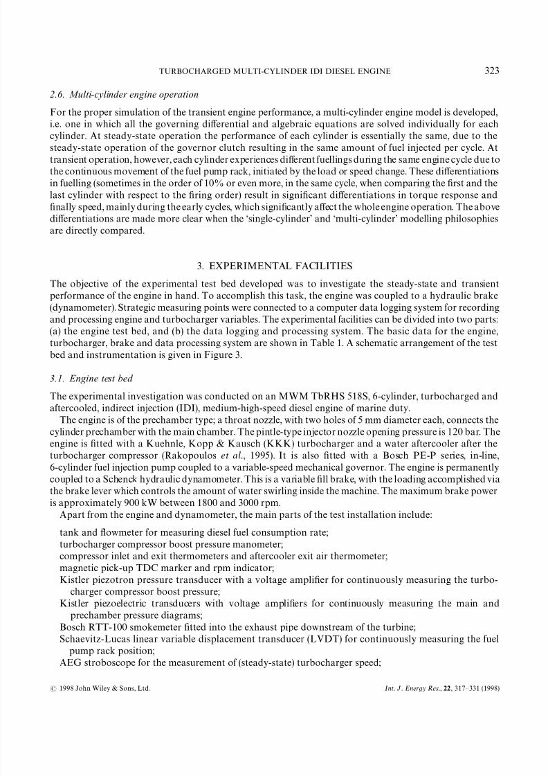
3. EXPERIMENTAL FACILITIES
The objective of the experimental test bed developed was to investigate the steady-state and transient
performance of the engine in hand. To accomplish this task, the engine was coupled to a hydraulic brake
(dynamometer). Strategic measuring points were connected to a computer data logging system for recording
and processing engine and turbocharger variables. The experimental facilities can be divided into two parts:
(a) the engine test bed, and (b) the data logging and processing system. The basic data for the engine,
turbocharger, brake and data processing system are shown in Table 1. A schematic arrangement of the test
bed and instrumentation is given in Figure 3.
3.1. Engine test bed
The experimental investigation was conducted on an MWM TbRHS 518S, 6-cylinder, turbocharged and
aftercooled, indirect injection (IDI), medium-high-speed diesel engine of marine duty.The engine is of the prechamber type; a throat nozzle, with two holes of 5 mm diameter each, connects the
cylinder prechamber with the main chamber. The pintle-type injector nozzle opening pressure is 120 bar. The
engine is fitted with a Kuehnle, Kopp & Kausch (KKK) turbocharger and a water aftercooler after the
turbocharger compressor (Rakopoulos et al., 1995). It is also fitted with a Bosch PE-P series, in-line,
6-cylinder fuel injection pump coupled to a variable-speed mechanical governor. The engine is permanently
coupled to a Schenck hydraulic dynamometer. This is a variable fill brake, with the loading accomplished via
the brake lever which controls the amount of water swirling inside the machine. The maximum brake power
is approximately 900 kW between 1800 and 3000 rpm.
Apart from the engine and dynamometer, the main parts of the test installation include:
tank and flowmeter for measuring diesel fuel consumption rate;
turbocharger compressor boost pressure manometer;compressor inlet and exit thermometers and aftercooler exit air thermometer;
magnetic pick-up TDC marker and rpm indicator;
Kistler piezotron pressure transducer with a voltage amplifier for continuously measuring the turbo-
charger compressor boost pressure;
Kistler piezoelectric transducers with voltage amplifiers for continuously measuring the main and
prechamber pressure diagrams;
Bosch RTT-100 smokemeter fitted into the exhaust pipe downstream of the turbine;
Schaevitz-Lucas linear variable displacement transducer (LVDT) for continuously measuring the fuel
pump rack position;
AEG stroboscope for the measurement of (steady-state) turbocharger speed;
TURBOCHARGED MULTI-CYLINDER IDI DIESEL ENGINE 323
1998 John Wiley & Sons, Ltd. Int. J. Energy Res., 22 , 317— 331 (1998)

7/26/2019 8IMP
http://slidepdf.com/reader/full/8imp 8/15
Figure 3. Schematic arrangement of the engine test bed and data logging system
J- and K-type thermocouples for measuring the temperatures of the exhaust gas after each cylinder and
downstream of the turbine;
Tektronix storage oscilloscope.
3.2. Data logging and processing system
The data acquisition and processing system for the engine test bed comprised:
(a) a Metrabyte DASH-16F, high-speed data acquisition card for measuring pressures, LVDT and TDC
signals,
(b) an Advantech PCL-818HD, high-speed data acquisition card with PCLD-789D expansion card for
various temperature measurements,
(c) two IBM compatible PCs, properly interfaced for fast data acquisition and recording, on the buses of
which the two cards mentioned above were mounted.
Both sampling systems use a fast 12-bit converter with an 8 s analogue-to-digital conversion time, giving
a maximum throughput rate of 100 kHz in Direct Memory Access (DMA) mode.
324 C. D. RAKOPOULOS, E. G. GIAKOUMIS AND D. T. HOUNTALAS
Int. J. Energy Res., 22 , 317— 331 (1998) 1998 John Wiley & Sons, Ltd.

7/26/2019 8IMP
http://slidepdf.com/reader/full/8imp 9/15
4. EXPERIMENTAL MEASUREMENTS AND THEORETICAL RESULTS
COMPARISON AND DISCUSSION
The first requirement from the engine test bed instrumentation was to investigate the steady-state perfor-
mance of the examined engine. For this purpose, an extended series of steady-state trials was conducted(covering the complete speed and load range of the engine) in order on the one hand to examine the model’s
predictive capabilities and on the other to calibrate successfully the individual submodels. By doing so, the
constants for the combustion, heat transfer, friction, soot emissions and turbocharger simulation were made
possible to be estimated.
Figure 4 shows a typical example of the acquired measurements together with the predicted results. This
figure concentrates on the operation of the engine, at 1250 rpm, extending from 25 to almost 90% of the full
engine load (corresponding fuelling rates of 13 to 37 kg h); it provides all the necessary properties for the
engine and turbocharger, i.e. engine power, bmep, brake-specific fuel consumption (bsfc), Bosch smoke
number, boost pressure, temperatures before and after the aftercooler, and turbocharger speed. The matching
between experimental and predicted results is very good for all the operating points. Even the smoke is
adequately (for a single-zone model) estimated, proving the relevant validity of equation (7). It is interesting
to note that even at extreme loads, such as 5 or 10% of the full load (not shown in Figure 4) which were initial
points for the transient tests discussed later in this section, the difference between experimental and simulated
results was never higher than 5%; this was also the case for every engine speed in the range of 1000 to
1500 rpm.
The second, and more difficult task, of the engine test bed instrumentation was the measurement and
processing of the transient operation of the engine. Two kinds of measurements were conducted, i.e.:
(a) rapid load changes (increases) with constant governor setting, commencing from various examined
(initial) engine speeds,
(b) rapid speed increases, under constant (initial) load.
Because the particular engine is a marine duty one with a relatively small speed range, the second type of
transient tests mentioned above was of lesser importance; automotive engines as for example reported in the
works of Watson and Marzouk (1977), Winterbone et al. (1977), Watson (1981) and Bazari (1994) are better
suited for such acceleration tests.
An extended spectrum of load and speed changes was examined for the particular engine. The initial load,
for a load increase, was usually 8— 10% of the full engine load at each initial engine speed examined. The final
applied load depended upon the specific trial, ranging from 50 to 95% of the full engine load. The initial
speed, for all speed increases, was 980— 1000 rpm (due to the already mentioned small speed range of the
engine), while here the initial load, constant for each trial, ranged from 3 to 5% of the full engine load so that
an adequately broad speed change, in the order of at least 350 rpm, could be made possible to be achieved.
During each transient case examined, the cylinder (main chamber) and turbocharger compressor pres-
sures, the TDC and the LVDT signals were measured at each °CA for at least 20 s (corresponding to roughly
200 engine cycles), so that a thermodynamic or simply dynamic equilibrium was always completed by thattime. The collection of all signals was accomplished with the ‘Streamer’ software (a factory code) which allows
input data to be directly stored on the PC hard disk at sampling rates of up to 60 000 samples per second,
which more than satisfies the requirements for the particular measurements. A special code written by the
authors in FORTRAN-77 language was then used for the translation of the acquired signals into physical
properties, as illustrated in Figures 5— 7, which present typical results obtained during the transient investiga-
tion process.
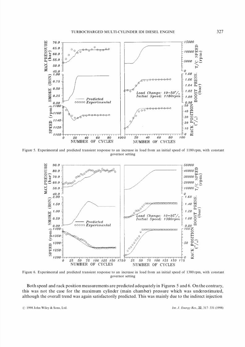
Figure 5, in particular, concentrates on the load increase commencing from 1180 rpm, with constant
governor setting. Here the initial load is 10% (of the full engine) load and the final load of 50% was applied
within 0)2 s. The application of the final load was effected by the movement of the brake control lever (this
task lasted 0)2 s), which in turn increased the amount of water inside the brake by appropriately increasing
TURBOCHARGED MULTI-CYLINDER IDI DIESEL ENGINE 325
1998 John Wiley & Sons, Ltd. Int. J. Energy Res., 22 , 317— 331 (1998)

7/26/2019 8IMP
http://slidepdf.com/reader/full/8imp 10/15
Figure 4. Experimental and predicted steady-state results for the engine operation at 1250 rpm as a function of fuelling rate (load)
the active surface of the inlet tube. However, this hydraulic brake is characterized by a high mass moment of
inertia, in the order of 5)375 kg m, resulting in long actual load-change times, a fact explaining the shift
observed in the measured engine speed during the first 20 cycles. This phenomenon was accounted for in the
simulation model by arbitrarily increasing the load appliance time. The overall matching between experi-
mental and predicted transient responses seems to be satisfactory for both engine and turbocharger variables.
The turbocharger compressor boost pressure and speed are both characterized by an initial delay in
response, of approximately 1)2 s or correspondingly 12 engine cycles; this is quite a common fact for such
load increases, which is in this case ‘boosted’ due to the relatively high moment of inertia of the turbocharger.
As a matter of fact, a high moment of inertia characterizes the whole dynamic system (due to the largeflywheel and brake) which leads eventually to small final speed droop, in the order of 25 rpm, and relatively
slow movement of the fuel pump rack position. This remark is made more obvious in Figure 6, where here
a 10— 95% load change is examined, commencing from 1380 rpm. The rack position needs 50 cycles (or more
than 4 s) to reach its extreme position corresponding to full fuelling. This results in rather low smoke
emissions ( just exceeding 1)50 in the Bosch scale), since the turbocharger lag does not become very important
here.
The above-mentioned shift in the engine speed signal, due to the slow (and by no means linear) load
appliance inside the brake, is also obvious in the boost pressure signal of Figure 6 by presenting a ‘stable
phase’ between cycles 30 and 40 before increasing again. Clearly, during this period the brake had
instantaneously stopped the loading process.
326 C. D. RAKOPOULOS, E. G. GIAKOUMIS AND D. T. HOUNTALAS
Int. J. Energy Res., 22 , 317— 331 (1998) 1998 John Wiley & Sons, Ltd.
7/26/2019 8IMP
http://slidepdf.com/reader/full/8imp 11/15
Figure 5. Experimental and predicted transient response to an increase in load from an initial speed of 1180 rpm, with constantgovernor setting
Figure 6. Experimental and predicted transient response to an increase in load from an initial speed of 1380 rpm, with constantgovernor setting
Both speed and rack position measurements are predicted adequately in Figures 5 and 6. On the contrary,
this was not the case for the maximum cylinder (main chamber) pressure which was underestimated,although the overall trend was again satisfactorily predicted. This was mainly due to the indirect injection
TURBOCHARGED MULTI-CYLINDER IDI DIESEL ENGINE 327
1998 John Wiley & Sons, Ltd. Int. J. Energy Res., 22 , 317— 331 (1998)

7/26/2019 8IMP
http://slidepdf.com/reader/full/8imp 12/15
Figure 7. Experimental and predicted transient response to an increase in speed demand, under constant (initial) load of 3%
nature of the engine combined with the turbocharging and perhaps a cyclic variation in the fuel pump
operation, which led to instantaneously forming very rich mixtures in the prechamber during a load increase,
resulting in a relatively high variation of pressures. This is more obvious in Figure 5, where a variationbetween 60 and 65 bar in maximum main chamber pressure is observed for the period between cycles 30 and
50, while both the engine speed and fuel pump rack position signals are essentially constant.
Figure 7 investigates an increase in speed demand under a constant load of 3% of the full engine load. This
increase was initiated by a rapid change in the governor control lever (setting). The fuel pump rack position
responded immediately, leading to full fuelling within 5 cycles and hence emissions of high amounts of soot
due to turbocharger lag. However, after the achievement of the desired final engine speed of 1350 rpm, the
smoke emissions are practically insignificant due to the very low final load of the engine. This is also the case
for the maximum cylinder pressure, which returns to the original value of 50 bar after the fall in the rack
position corresponding to the final 5% load. Between cycles 5 and 15, where the rack possessed its extreme
position, the corresponding fuelling curve presented a slow falling trend; this is due to the characteristic of the
particular fuel pump, as already illustrated in Figure 2, of decreasing injected fuel quantity with increasing
speed, resulting in the falling trend observed in the Bosch smoke number.
5. CONCLUSIONS
A digital computer model was developed to study the transient performance of IDI, turbocharged, multi-
cylinder diesel engine operation, under load or speed changes. A model incorporating some important new
transient features concerning combustion, heat transfer and dynamic analysis was further improved to
account for transient mechanical friction and turbocharger operation, while it was modified so as every
cylinder was treated individually. Thus, account was taken of the special characteristics of the transient
response by diversifying it completely from the steady-state modelling philosophy.
328 C. D. RAKOPOULOS, E. G. GIAKOUMIS AND D. T. HOUNTALAS
Int. J. Energy Res., 22 , 317— 331 (1998) 1998 John Wiley & Sons, Ltd.

7/26/2019 8IMP
http://slidepdf.com/reader/full/8imp 13/15
An engine test bed instrumentation connected to a high-speed data acquisition system was set up to
investigate the model’s predictive capabilities, under both steady-state and transient operations. The indirect
injection nature of the engine as well as the brake used were important challenges for the validity of the
simulation model developed. The engine in hand had a large moment of inertia (two or three times more than
the usual configurations) which led to practically smokefree operation under any load changes due to the
slow movement of the rack. However, this was not the case for the speed changes, where the soot emissions
exceeded the acceptable values during the early cycles. The model predicted satisfactorily all the basic engine
and turbocharger variables responses during all transient operations, while revealing some important aspects
of the engine behaviour under various transient operating schedules.
ACKNOWLEDGEMENTS
The authors gratefully acknowledge the assistance offered by Mr Dimitrof and Mrs Schmidt (Carl Schenck
AG, Darmstadt), Mr Kampa (Robert Bosch GmbH, Stuttgart) and Dr Mayer (Kuenhle, Kopp & Kausch AG,
Frankenthal, Pfalz), who provided useful data concerning the experimental facilities.
NOMENCLATURE
bmep "brake mean effective pressure, barc "constantsG "moment of inertia, kg m
k "load torque constant, N m s
N "engine speed, rpmp "pressure, barr "compressor pressure ratio
¹ "temperature, K, or torque, N mt "time, s
Greek letters
"angular acceleration, s
"ratio of crank radius to connecting rod length
"crank angle, deg (measured from the TDC position)
"angular velocity, s
Subscripts
ac "
aftercoolerC "compressor
e "engine
fr "friction
L "load
st "steady state
TC "turbocharger
tr "transient
Superscripts
o "nominal conditions
TURBOCHARGED MULTI-CYLINDER IDI DIESEL ENGINE 329
1998 John Wiley & Sons, Ltd. Int. J. Energy Res., 22 , 317— 331 (1998)

7/26/2019 8IMP
http://slidepdf.com/reader/full/8imp 14/15
Abbreviations
°CA "degrees crank angle
BDC "bottom dead centre
LVDT "linear variable displacement transducer
rpm "revolutions per minute
TDC "top dead centre
REFERENCES
Arcoumanis, C., Megaritis, A. and Bazari, Z. (1994). ‘Analysis of transient exhaust emissions in a turbocharged vehicle diesel engine’,Proc. Conf . on ¹urbocharging and ¹urbochargers, Inst. Mech. Engrs, London, U.K., Paper C484/038, pp. 71— 81.
Bazari, Z. (1994). ‘Diesel exhaust emissions prediction under transient operating conditions’, Society of Automotive Engineers (American),SAE paper 940666.
Benson, R. S. and Whitehouse, N. D. (1979). Internal Combustion Engines, Pergamon, Oxford, U.K.Heywood, J. B. (1988). Internal Combustion Engine Fundamentals, McGraw— Hill, New York, U.S.A.Hong, G., Collings, N. and Baker, N. J. (1987). ‘Diesel smoke transient control using a real time smoke sensor’, Society of Automotive
Engineers (American), SAE paper 871629.Horlock, J. H. and Winterbone, D. E. (1986). ¹he ¹hermodynamics and Gas Dynamics of Internal Combustion Engines, »ol. II,
Clarendon, Oxford, U.K.Jiang, Q. and Van Gerpen, J. H. (1992). ‘Prediction of diesel engine particulate emission during transient cycles’, Society of Automotive
Engineers (American), SAE paper 920466.Kouremenos, D. A., Rakopoulos, C. D. and Hountalas, D. T. (1990). ‘Thermodynamic analysis of indirect injection diesel engines by
two-zone modelling of combustion’, ¹rans. ASME, J . Engng Gas ¹urbines and Power, 112, 138— 149.Kouremenos, D. A., Rakopoulos, C. D., Hountalas, D. T. and Kotsiopoulos, P. N. (1991). ‘A simulation technique for the fuel injection
system of diesel engines’, American Society of Mechanical Engineers Winter Annual Meeting, Atlanta, GA, U.S.A., Proc. AdvancedEnergy Systems, 24, 91— 102.
Ledger, J. D. and Walmsley, S. (1971). ‘Computer simulation of a turbocharged diesel engine operating under transient load conditions’,Society of Automotive Engineers (American), SAE paper 710177.
Murayama, T., Miyamoto, N., Tsuda, T., Suzuki, M. and Hasegawa, S. (1980). ‘Combustion behaviors under accelerating operation of an IDI diesel engine’, Society of Automotive Engineers (American), SAE paper 800966.
Pilley, A. D., Noble, A. D., Beaumont, A. J., Needham, J. R. and Porter, B. C. (1989). ‘Optimization of heavy-duty diesel engine
transient emissions by advanced control of a variable geometry turbine’, Society of Automotive Engineers (American), SAE paper890395.Qiao, J., Dent, J. C. and Garner, C. P. (1992). ‘Diesel engine modelling under steady and transient conditions using a transputer based
concurrent computer’, Society of Automotive Engineers (American), SAE paper 922226.Rackmil, C. I. and Blumberg, P. N. (1989). ‘Dynamic simulation of a turbocharged intercooled diesel engine with rack-actuated
electronic fuel control system’, Society of Automotive Engineers (American), SAE paper 890394.Rakopoulos, C. D. and Giakoumis, E. G. (1997a). ‘Development of cumulative and availability rate balances in a multi-cylinder
turbocharged IDI diesel engine’, Energy Convers. Mgmt., 38, 347— 379.Rakopoulos, C. D. and Giakoumis, E. G. (1997b). ‘Simulation and analysis of a naturally aspirated IDI diesel engine under transient
conditions comprising the effect of various dynamic and thermodynamic parameters’, Energy Convers. Mgmt (in press).Rakopoulos, C. D. and Giakoumis, E. G. (1997c). ‘Simulation and exergy analysis of transient diesel-engine operation’, Energy Int. J .
22, 875— 885.Rakopoulos, C. D. and Mavropoulos, G. C. (1996). ‘Study of the steady and transient temperature field and heat flow in the combustion
chamber components of a medium speed diesel engine using finite element analyses’, Energy Res., 20, 437— 464.Rakopoulos, C. D., Andritsakis, E. C. and Hountalas, D. T. (1995). ‘The influence of the exhaust system unsteady gas flow and insulation
on the performance of a multi-cylinder turbocharged diesel engine’, Heat Recovery Systems & CHP, 15 , 51— 72.Rakopoulos, C. D., Giakoumis, E. G. and Hountalas, D. T. (1997a). ‘A simulation analysis of the effect of governor technical
characteristics and type on the transient performance of a naturally aspirated IDI diesel engine’, Society of Automotive Engineers(American), SAE paper 970633.
Rakopoulos, C. D., Hountalas, D. T., Mavropoulos, G. C. and Giakoumis, E. G. (1997b). ‘An integrated transient analysis simulationmodel applied in thermal loading calculations of an air-cooled diesel engine under variable speed and load conditions’, Society of Automotive Engineers (American), SAE paper 970634.
Rezeka, S. F. and Henein, N. A. (1984). ‘A new approach to evaluate instantaneous friction and its components in internal combustionengines’, Society of Automotive Engineers (American), SAE paper 840179.
Taylor, C. F., (1985). ¹he Internal Combustion Engine in ¹heory and Practice, »ol. 2, MIT, Cambridge, MA. U.S.A.Watson, N. (1981). ‘Transient performance simulation and analysis of turbocharged diesel engines’, Society of Automotive Engineers
(American), SAE paper 810338.Watson, N. and Janota, M. S. (1982). ¹urbocharging the Internal Combustion Engine, MacMillan, London, U.K.Watson, N. and Marzouk, M. (1977). ‘A non-linear digital simulation of turbocharged diesel engines under transient conditions’, Society
of Automotive Engineers (American), SAE paper 770123.
330 C. D. RAKOPOULOS, E. G. GIAKOUMIS AND D. T. HOUNTALAS
Int. J. Energy Res., 22 , 317— 331 (1998) 1998 John Wiley & Sons, Ltd.

7/26/2019 8IMP
http://slidepdf.com/reader/full/8imp 15/15
Winterbone, D. E. and Tennant, D. W. H. (1981). ‘The variation of friction and combustion rates during diesel engine transients’, Societyof Automotive Engineers (American), SAE paper 810339.
Winterbone, D. E., Benson, R. S., Closs, G. D. and Mortimer, A. G. (1976). ‘A comparison between experimental and analytical transienttest results for a turbocharged diesel engine’, Proc. Inst. Mech. Engrs, 190, 267— 276.
Winterbone, D. E., Benson, R. S., Mortimer, A. G., Kenyon, P. and Stotter, A. (1977). ‘Transient response of turbocharged diesel engines’,Society of Automotive Engineers (American), SAE paper 770122.
Zellbeck, H. and Woschni, G. (1983). ‘Rechnerische Untersuchung des dynamischen Betriebsverhaltens aufgeladener Dieselmotoren’,Motor-¹echnische Zeitschrift (German), 44, 81— 86.
TURBOCHARGED MULTI-CYLINDER IDI DIESEL ENGINE 331
1998 John Wiley & Sons, Ltd. Int. J. Energy Res., 22 , 317— 331 (1998)


