Embed Size (px)
Citation preview

8901 Access Control Panel Installation Guide __________________________________________________________________________
_______________________________________________________________________________________________________________
Version C. 2014-05-21 Design . Innovations Page 1 of 17
1. Introduction 2. Technical Specification 3. System Deployment 4. Panel Layout 5. Detailed Pin Assignment
6. Panel Configuration 7. Sample Connection Circuits
System Reader Electrical Lock Door Alarm Door Ajar Door Sensor Release Button Panel Tamper
8901 Access Control Panel Installation Guide __________________________________________________________________________
_______________________________________________________________________________________________________________
Version C. 2014-05-21 Design . Innovations Page 2 of 17
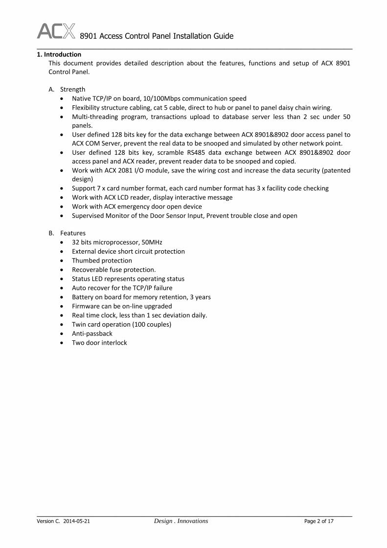
1. Introduction This document provides detailed description about the features, functions and setup of ACX 8901 Control Panel. A. Strength
Native TCP/IP on board, 10/100Mbps communication speed
Flexibility structure cabling, cat 5 cable, direct to hub or panel to panel daisy chain wiring.
Multi-threading program, transactions upload to database server less than 2 sec under 50 panels.
User defined 128 bits key for the data exchange between ACX 8901&8902 door access panel to ACX COM Server, prevent the real data to be snooped and simulated by other network point.
User defined 128 bits key, scramble RS485 data exchange between ACX 8901&8902 door access panel and ACX reader, prevent reader data to be snooped and copied.
Work with ACX 2081 I/O module, save the wiring cost and increase the data security (patented design)
Support 7 x card number format, each card number format has 3 x facility code checking
Work with ACX LCD reader, display interactive message
Work with ACX emergency door open device
Supervised Monitor of the Door Sensor Input, Prevent trouble close and open
B. Features
32 bits microprocessor, 50MHz
External device short circuit protection
Thumbed protection
Recoverable fuse protection.
Status LED represents operating status
Auto recover for the TCP/IP failure
Battery on board for memory retention, 3 years
Firmware can be on-line upgraded
Real time clock, less than 1 sec deviation daily.
Twin card operation (100 couples)
Anti-passback
Two door interlock

8901 Access Control Panel Installation Guide __________________________________________________________________________
_______________________________________________________________________________________________________________
Version C. 2014-05-21 Design . Innovations Page 3 of 17
C. Panel Appearance

8901 Access Control Panel Installation Guide __________________________________________________________________________
_______________________________________________________________________________________________________________
Version C. 2014-05-21 Design . Innovations Page 4 of 17
2. Technical Specification
Specification 8901
Panel Inputs
- 1 x IN and 1 x OUT Wigand reader or;
- 1 x IN and 1 x OUT ACX scramble RS485 reader
- 1 x door sensor input
- 1 x request to exit input
- 1 x auxiliary input
- 1 x controller box tamper input
- 1 x ACX high security key open door device
- Power input monitoring : A.C. / D.C. / Backup Battary
- Work with ACX high security door emergency open
device, couple with random key switch & reset panel.
Panel Outputs
- 1 x E-Lock relay dry contact output, max. 10A current
rating
- 1 x Alarm relay dry contact output, max. 3A current rating
- 1 x Door ajar TTL signal output, 5VDC output, 20mA
- 12.8VDC battery charging
Memory
- 38,000 cardholders, each card holder has 24 bytes content
- 45,000 swipe card records
- 800 events
PCB Dimension 120mm x 120mm x 12mm
Expansion 1 x RS485 serial port for expansion, software and hardware
interface to other system
Holidays 100 Holiday dates
Timezone
- 80 x access control time zone
- 1 x password time zone
- 1 x electric Lock time zone
- 1 x alarm time zone
- 1 x door ajar time zone
- 1 x request to exit time zone
- 1 x twin card operation time zone
All timezone can be assigned from Monday to Sunday and
Holiday, 4 intervals per day, time zone can be selected
globally or individually
Password
- User password, timezone control
- Global password, key in the password through keypad
reader open door
- Duress password, open door but trigger alarm output
Communication
- Panel to hub, CAT 5 cable (max. 100 meters)
- Panel to panel, daisy chain by CAT 5 cable (max. 100
meters)
8901 Access Control Panel Installation Guide __________________________________________________________________________
_______________________________________________________________________________________________________________
Version C. 2014-05-21 Design . Innovations Page 5 of 17
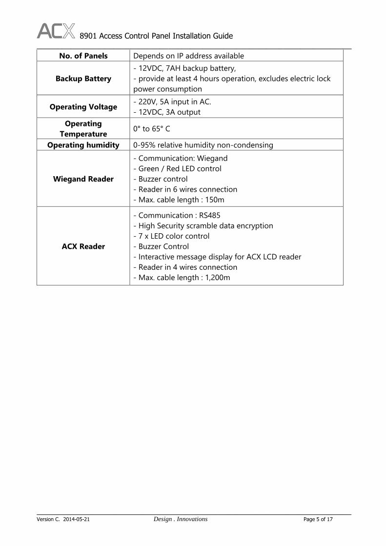
No. of Panels Depends on IP address available
Backup Battery
- 12VDC, 7AH backup battery,
- provide at least 4 hours operation, excludes electric lock
power consumption
Operating Voltage - 220V, 5A input in AC.
- 12VDC, 3A output
Operating
Temperature 0° to 65° C
Operating humidity 0-95% relative humidity non-condensing
Wiegand Reader
- Communication: Wiegand
- Green / Red LED control
- Buzzer control
- Reader in 6 wires connection
- Max. cable length : 150m
ACX Reader
- Communication : RS485
- High Security scramble data encryption
- 7 x LED color control
- Buzzer Control
- Interactive message display for ACX LCD reader
- Reader in 4 wires connection
- Max. cable length : 1,200m
8901 Access Control Panel Installation Guide __________________________________________________________________________
_______________________________________________________________________________________________________________
Version C. 2014-05-21 Design . Innovations Page 6 of 17
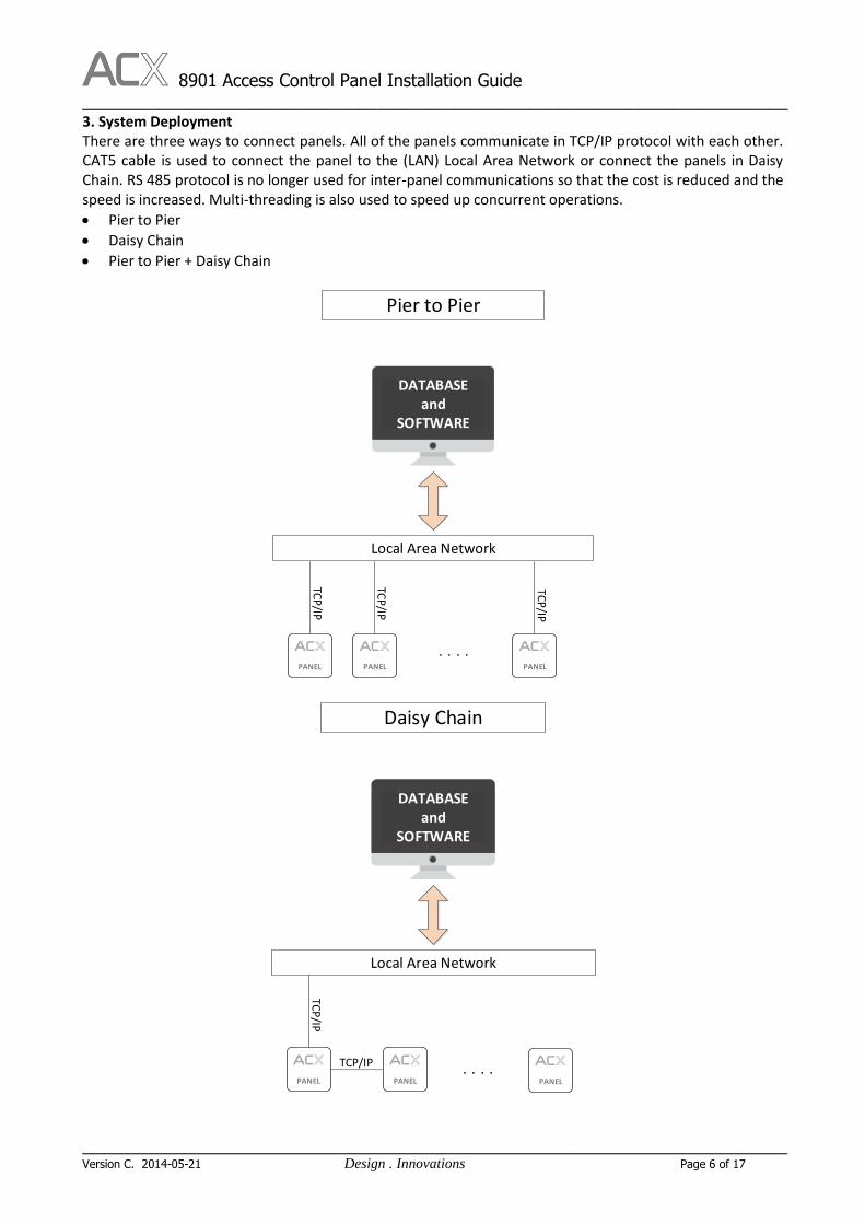
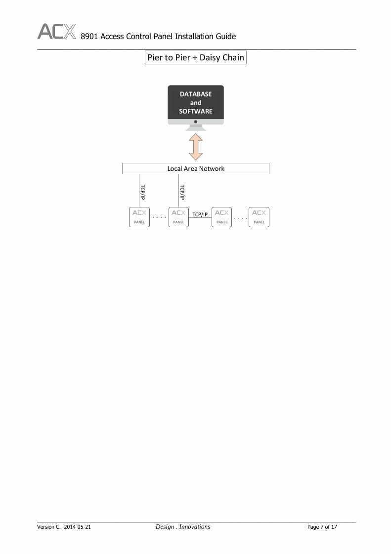
3. System Deployment There are three ways to connect panels. All of the panels communicate in TCP/IP protocol with each other. CAT5 cable is used to connect the panel to the (LAN) Local Area Network or connect the panels in Daisy Chain. RS 485 protocol is no longer used for inter-panel communications so that the cost is reduced and the speed is increased. Multi-threading is also used to speed up concurrent operations.
Pier to Pier
Daisy Chain
Pier to Pier + Daisy Chain
Local Area Network
. . . .
Pier to Pier
DATABASE and
SOFTWARE
PANEL PANELPANEL
TCP
/IP
TCP
/IP
TCP
/IP
Local Area Network
. . . .
Daisy Chain
DATABASE and
SOFTWARE
PANEL
TCP
/IP
TCP/IP
PANELPANEL
8901 Access Control Panel Installation Guide __________________________________________________________________________
_______________________________________________________________________________________________________________
Version C. 2014-05-21 Design . Innovations Page 7 of 17
Local Area Network
. . . .
Pier to Pier + Daisy Chain
DATABASE and
SOFTWARE
PANEL PANEL
TCP
/IP
TCP
/IP
PANEL
TCP/IP . . . .PANEL

8901 Access Control Panel Installation Guide __________________________________________________________________________
_______________________________________________________________________________________________________________
Version C. 2014-05-21 Design . Innovations Page 8 of 17
4. Panel Layout
RJ4
5R
J45
ACX 8901 Single Door TCP/IP Panel
C2 : NO / NC / COM / PWR / GND (1)C3 : Door Ajar / NO / NC / COM (1)
C4 : Door Sensor / GND / RTE / GND (1)
- AUX IN - Tamper
2 x Wiegand or ACX Scramble RS485 readerPower / Ground / D0 / D1 / ACK / Buzzer / RS485 T+ / RS485 T-
12VDC, 3ADC
RS485 Port (for future use)
For Emergency Door open Device
AC / DC / Backup battery monitoring
120mm
120m
m
C1
C2 C3 C4 C5
C6
C7
C8
C10 C9
Start from the left is PIN 1 when face the terminal

8901 Access Control Panel Installation Guide __________________________________________________________________________
_______________________________________________________________________________________________________________
Version C. 2014-05-21 Design . Innovations Page 9 of 17
5. Detailed Pin Assignment
8901 Single Door TCP/IP Controller Connector Summary PIN Description
C1 Power Input 1 12VDC, 3ADC
2 Ground
C2
E-Lock Power (12V, 1.5A)
1 Ground
2 Power
E-Lock Output (Dry Contact)
3 COM
4 NC
5 NO
C3
Door Alarm Output (Dry Contact)
1 COM
2 NC
3 NO
Door Ajar Output 4 Normal is 0VDC, Door Ajar 5VDC, 200mA output
C4
Door Sensor 1 Door Sensor
2 Ground
Release Button 3 Release button
4 Ground
C5
AUX INPUT 1 IN#1
2 Ground
Panel Tamper 3 Tamper
4 Ground
C6 RS485 Port (Custom use)
1 RS485 (T+)
2 RS485 (T-)
3 RS485 (T+)
4 RS485 (T-)
C7 For Emergency Door Open Device
1 Power Out (12VDC, 100mA)
2 Ground
3 Signal +
4 Signal -
C8 Power Status 1 DC Power
2 Backup Battery

8901 Access Control Panel Installation Guide __________________________________________________________________________
_______________________________________________________________________________________________________________
Version C. 2014-05-21 Design . Innovations Page 10 of 17
3 A.C. Power
4 Ground
C9 OUT Reader
1 Reader Power (200mA)
2 Ground
3 Data 0
4 Data 1
5 Green LED (ACK)
6 Buzzer
7 RS485 (T+) ACX RS485 reader only
8 RS485 (T-) ACX RS485 reader only
C10 IN Reader
1 Reader Power (200mA)
2 Ground
3 Data 0
4 Data 1
5 Green LED (ACK)
6 Buzzer
7 RS485 (T+) ACX RS485 reader only
8 RS485 (T-) ACX RS485 reader only
RJ45 2 Ports TCP/IP Switch 1
Connect to TCP/IP swtich or next Panel 2

8901 Access Control Panel Installation Guide __________________________________________________________________________
_______________________________________________________________________________________________________________
Version C. 2014-05-21 Design . Innovations Page 11 of 17
6. Panel Configuration
Panel Address
1. Go to the IP Config folder under the Installation folder (Normally C:\Program Files (x86)\ACX\X.90
Access Control System\Set IP Config). Open the IP Configuration utility program.
2. Click “Scan” button.
3. Select the device and modify the IP Address or other parameters. Input the PWD and Click “Set” button
to download configuration to the board.
Remark: The Default Key is 123456

8901 Access Control Panel Installation Guide __________________________________________________________________________
_______________________________________________________________________________________________________________
Version C. 2014-05-21 Design . Innovations Page 12 of 17
7. Sample Connection Circuits
A. System
Daisy Chain
Server
LAN
TCP/IP
TCP/IP
TCP
/IP
8901/8902PANEL
8901/8902PANEL
8901/8902PANEL
Hub

8901 Access Control Panel Installation Guide __________________________________________________________________________
_______________________________________________________________________________________________________________
Version C. 2014-05-21 Design . Innovations Page 13 of 17
B. Reader
Reader: C9, C10
Wire Color:
1. Red Reader Power
2. Black Ground
3. Green Data 0
4. White Data 1
5. Orange Green LED (ACK)
6. Yellow Buzzer
7. Purple RS485 (T+)
8. Grey RS485 (T-)
Wiegand Reader
1 2 3 4 5 6 7 8
Wiegand Reader
ACX Scramble RS485 Reader
(Improved Security)
1 2 3 4 5 6 7 8
ScrambleRS 485 Reader
8901 Access Control Panel Installation Guide __________________________________________________________________________
_______________________________________________________________________________________________________________
Version C. 2014-05-21 Design . Innovations Page 14 of 17
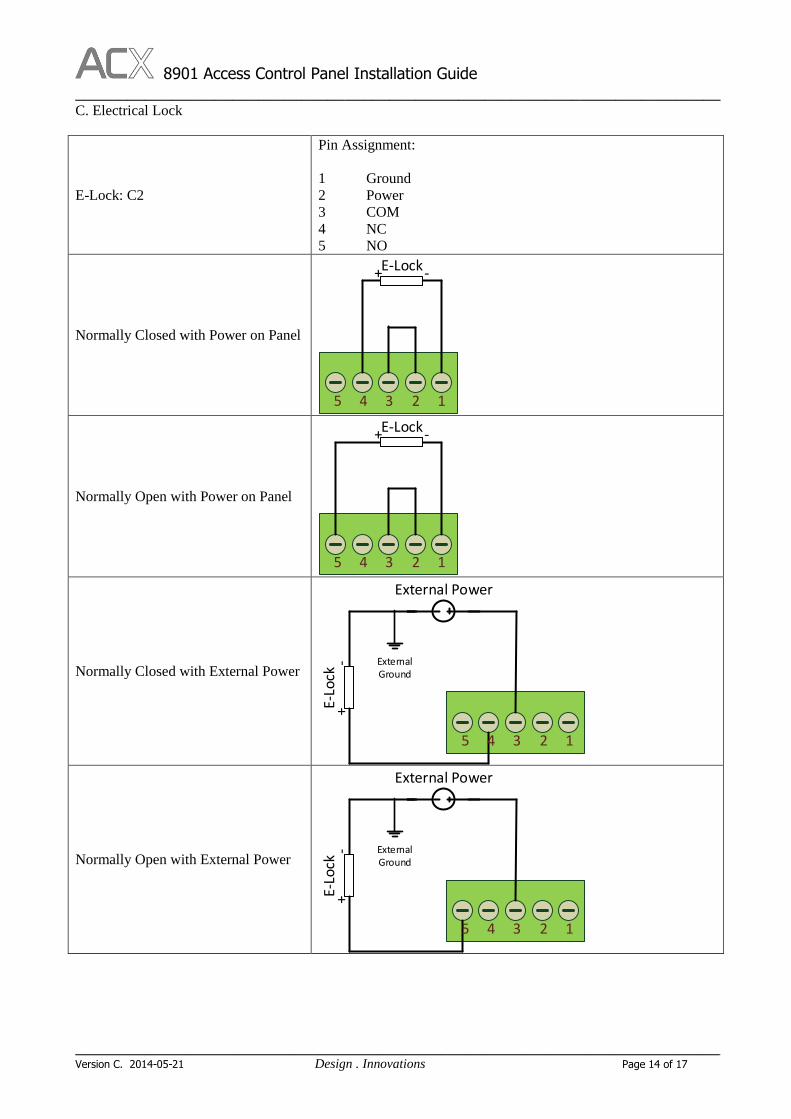
C. Electrical Lock
E-Lock: C2
Pin Assignment:
1 Ground
2 Power
3 COM
4 NC
5 NO
Normally Closed with Power on Panel
E-Lock+ -
5 4 3 2 1
Normally Open with Power on Panel
E-Lock+ -
5 4 3 2 1
Normally Closed with External Power
E-Lo
ck+
-
External Power
5 4 3 2 1
ExternalGround
Normally Open with External Power
E-Lo
ck+
-
External Power
5 4 3 2 1
ExternalGround
8901 Access Control Panel Installation Guide __________________________________________________________________________
_______________________________________________________________________________________________________________
Version C. 2014-05-21 Design . Innovations Page 15 of 17
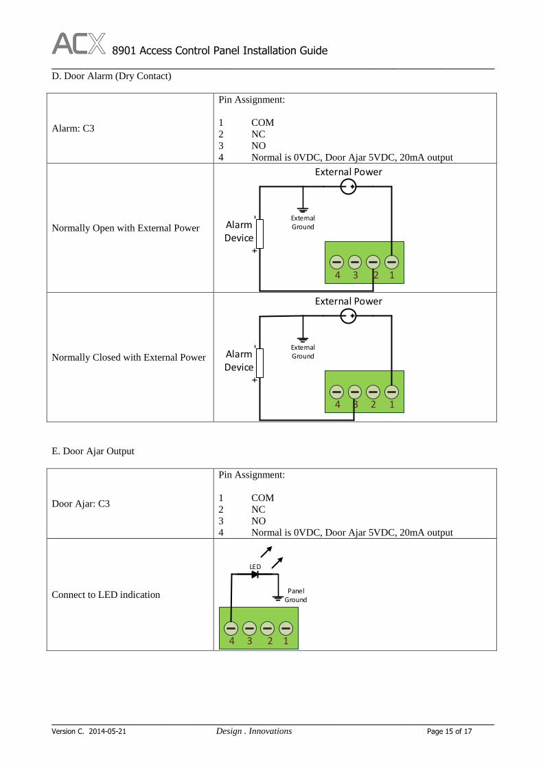
D. Door Alarm (Dry Contact)
Alarm: C3
Pin Assignment:
1 COM
2 NC
3 NO
4 Normal is 0VDC, Door Ajar 5VDC, 20mA output
Normally Open with External Power
4 3 2 1
Alarm Device
+-
External Power
ExternalGround
Normally Closed with External Power
4 3 2 1
Alarm Device
+-
External Power
ExternalGround
E. Door Ajar Output
Door Ajar: C3
Pin Assignment:
1 COM
2 NC
3 NO
4 Normal is 0VDC, Door Ajar 5VDC, 20mA output
Connect to LED indication
4 3 2 1
PanelGround
LED
8901 Access Control Panel Installation Guide __________________________________________________________________________
_______________________________________________________________________________________________________________
Version C. 2014-05-21 Design . Innovations Page 16 of 17
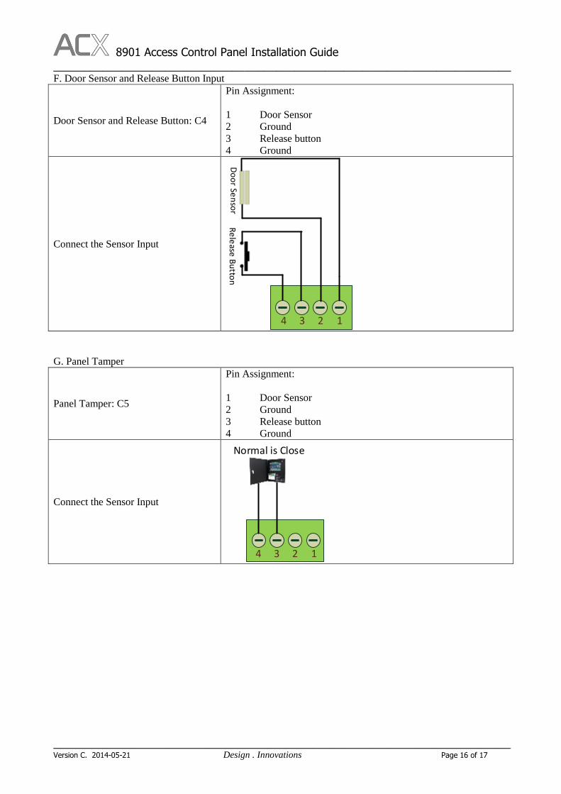
F. Door Sensor and Release Button Input
Door Sensor and Release Button: C4
Pin Assignment:
1 Door Sensor
2 Ground
3 Release button
4 Ground
Connect the Sensor Input
4 3 2 1R
ele
ase B
utto
nD
oo
r Sen
sor
G. Panel Tamper
Panel Tamper: C5
Pin Assignment:
1 Door Sensor
2 Ground
3 Release button
4 Ground
Connect the Sensor Input
4 3 2 1
Normal is Close
8901 Access Control Panel Installation Guide __________________________________________________________________________
_______________________________________________________________________________________________________________
Version C. 2014-05-21 Design . Innovations Page 17 of 17
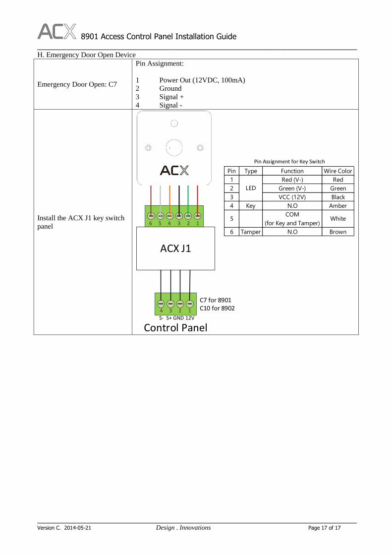
H. Emergency Door Open Device
Emergency Door Open: C7
Pin Assignment:
1 Power Out (12VDC, 100mA)
2 Ground
3 Signal +
4 Signal -
Install the ACX J1 key switch
panel
4 3 2 1
ACX J1
6 5 4 3 2 1
Control PanelS- S+ GND 12V
Pin Type Function Wire Color
1 Red (V-) Red
2 Green (V-) Green
3 VCC (12V) Black
4 Key N.O Amber
5COM
(for Key and Tamper)White
6 Tamper N.O Brown
LED
Pin Assignment for Key Switch
C7 for 8901C10 for 8902