Embed Size (px)
Citation preview

8900 DeSoto Avenue Canoga Park, California 91304
NOTICE
This report was prepared as an account of work sponsored by the United States Government. Neither the United States nor the United States Department of Energy, nor any of their employees, nor any of their contractors, subcontractors, or their employees, makes any warranty, express or implied, or assumes any legal liability or responsibility for the accuracy, completeness or useful- ness of any information, apparatus, product or process disclosed, or represents that its use would not infringe privately owned rights.

. . . . . . . . . . . . . . . . . . . . . . . . . . . . . . . . . Abstract
. . . . . . . . . . . . . . . . . . . . . . . . . . . . . . . 1.0 General
. . . . . . . . . . . . . . . . . . . . . . . . . 1.1 Faci 1 i t y Name
. . . . . . . . . . . . . . . . . . . . . . . . . . 1.2 Af f i l i a t i on
. . . . . . . . . . . . . . . . . . . . . . . . . . . . 1.3 Location
. . . . . . . . . . . . . . . . . . . 2.0 Fac i l i ty Type and Power Rating
2.1 Physical Dimensions and Power Rating . . . . . . . . . . . . . . . . . . . . . . . . . . . . . . . . . . . . 2 . 2 System Description
. . . . . . . . . 2.3 Operating History Relating t o Decommissioning
2.3.1 Data Supporting the Presence of Activation o r . . . . . . . . . . . . . . . . . . . . . Contamination
2.3.2 Special Data on Incidents That Could Be Signif icant t o the Appraisal of Activation o r Contamination . . . . .
3.0 Construction . . . . . . . . . . . . . . . . . . . . . . . . . . . . . . . . . . . . . . . . . . . . . . . . . . . . 3.1 Nuclear Designer
. . . . . . . . . . . . . . . . . . . . . . . 3.2 Fac i l i t y Designer
. . . . . . . . . . . . . . . 3.3 Date and Duration of Construction
. . . . . . . . . . . . . . . . . . . . 3.4 Construction Photographs . . . . . . . . . . . . . . . . . . . . . 4.0 Decomissioning Objectives
. . . . . . . . . . . . . . . . . . . . . . . . . . . . . . 4.1 Mode
. . . . . . . . . . . . . . . . . . . . 4.2 Regulatory Requirements
. . . . . . . . . . . . . . 4.2 .1 Governing Regulatory Agencies
. . . . . . . . . . . . . . . . . 4.2.2 Licensing Requirements
4.2.3 Upper Radiation Level Limits Including As-Low-As- Practicable Considerations . . . . . . . . . . . . . . .
. . . 4.2.4 Decommissioning Operational Regulatory Requi rements . . . . . . . . . . . . . 4.3 Summary of Decommissioning Procedures
4.3.1 Decontamination and Razing Techniques . . . . . . . . . . 4.3.2 Special Tooling. Equipment. o r Techniques Required . . . 4.3.3 Special Access o r S i t e Problems Affecting
Decommissioning . . . . . . . . . . . . . . . . . . . . . . . . . . . . . . . . . . . . . . 4.4 Subsequent Fac i l i ty Use Plans
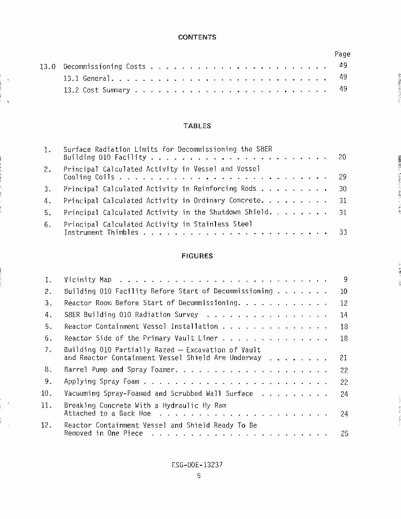
Page
7
9
9
9
9
10
10

Page
Faci 1 i t y Radioact ivi ty S ta tus . . . . . . . . . . . . . . . . . . . 29
5 .1 Pre-Decommissioning Curie Inventory of Activated . . . . . . . . . . . . . . St ruc tu re . Mater ia ls . and Equipment 29
5.2 Decommissioning Radiological Survey of Buildings. I n t e r i o r s . and Support Systems . . . . . . . . . . . . . . . . 33
5.3 Final Radiological Survey of Remaining F a c i l i t i e s Equipment. Materials . and Systems . . . . . . . . . . . . . . . 35
Quanti t i e s of Radioacti ve Waste Processed . . . . . . . . . . . . . 37
6.1 Construction Materials -- Volume and Tonnage . . . . . . . . . . 37
6.2 Reactor Support System -- Volume and Tonnage . . . . . . . . . . 37
Transportat ion and Burial of Radioactive Waste . . . . . . . . . . . 39
7.1 Low Spec i f i c Ac t iv i ty (LSA) and High Spec i f i c Act iv i ty (HSA) Transportat ion and Burial Cost . . . . . . . . . 39
7.1.1 Special Packaging Costs . . . . . . . . . . . . . . . . 39
7.2 Disposi t ion S i t e . . . . . . . . . . . . . . . . . . . . . . . 39
Personnel Radioact iv i ty Exposure Log . . . . . . . . . . . . . . . . 41
8 .1 Total Man-rem f o r P ro jec t . . . . . . . . . . . . . . . . . . 41
8.2 Maximum Individual Dose . . . . . . . . . . . . . . . . . . . . 41
8. 3 Average Individual Dose . . . . . . . . . . . . . . . . . . . . 41
Health Physics . . . . . . . . . . . . . . . . . . . . . . . . . . . 42
9.1 Public and Personnel Safety . . . . . . . . . . . . . . . . . . 43
9.2 Protec t ive Procedures . . . . . . . . . . . . . . . . . . . . . 43
9.3 Equipment. Materials . and Instrumentation Requirements . . . . 44
9.4 On-Going Radiation Surveys and Records . . . . . . . . . . . . 44
9.5 Health Physics Costs . . . . . . . . . . . . . . . . . . . . . 45
Recoverable Costs . . . . . . . . . . . . . . . . . . . . . . . . . 46
10.1 Sal vageabl e Material and Equipment . . . . . . . . . . . . . . 46
10.2 F a c i l i t i e s and S i t e . . . . . . . . . . . . . . . . . . . . . 46
anpower Expenditure . . . . . . . . . . . . . . . . . . . 47
11.1 Administrative . . . . . . . . . . . . . . . . . . . . . . . . 47
11.2 Engineering and Labor . . . . . . . . . . . . . . . . . . . . . 47
11.3 Special Purchased Services . . . . . . . . . . . . . . . . . . 47
Projec t Schedule . . . . . . . . . . . . . . . . . . . . . . . . . . 48
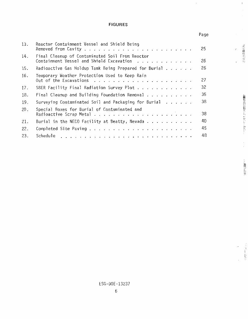
Page
Reactor Containment Vessel and Shie ld Being . . . . . . . . . . . . . . . . . . . . . . . Removed from Cavity 25
Final Cleanup of Contaminated Soi l From Reactor . . . . . . . . . . . . Containment Vessel and Shield Excavation 26
. . . . . . Radioactive Gas Holdup Tank Being Prepared f o r Burial 26
Temporary Weather Pro tec t ion Used t o Keep Rain . . . . . . . . . . . . . . . . . . . . . O u t of t he Excavations 27
S8ER F a c i l i t y Final Radiation Survey P l o t . . . . . . . . . . . . 32
Final Cleanup and Building Foundation Removal . . . . . . . . . . 35
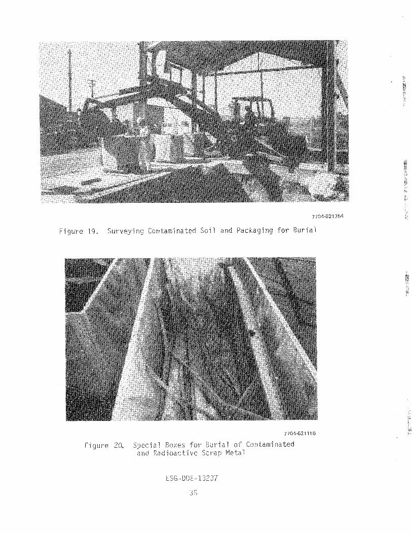
Surveying Contaminated Soi l and Packaging f o r Burial . . . . . . 38
Special Boxes f o r Burial of Contaminated and Radioactive Scrap e ta1 . . . . . . . . . . . . . . . . . . . . . 38
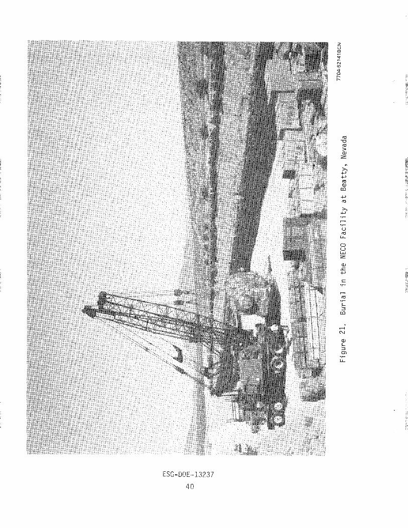
Burial i n t h e NECO F a c i l i t y a t Beatty . Nevada . . . . . . . . . . 40
Completed S i t e Paving . . . . . . . . . . . . . . . . . . . . . . 45
. . . . . . . . . . . . . . . . . . . . . . . . . . . . Schedule 48

I n 1974, the SNAP 8 Experimental Reactor (S8ER) Facili ty a t the Santa
Susana Field Laboratories (SSFL) of the Energy Systems Group (ESG) of Rockwell
International was declared excess to the government's program needs. The
resulting decommissioning program, commenced in 1976, provided for complete t
removal of a l l radioactive materials remaining from the operation of two SNAP
space-type compact reactors. Careful study indicated that the safest and most
economical removal of the reactor containment vessel, which had induced radio-
act ivi ty and was located in the building, would be by to ta l ly razing the
f ac i l i t y .
To safeguard against any inadvertent spread of radioactive material, the
steel-frame building i t s e l f was used to provide as much weather and wind pro-
tection for the radioactive material removal ac t iv i t i e s as possible; therefore,
i t was taken down in pieces as the excavation progressed and control measures
permitted. Concrete substructure vaults were decontaminated and demolished
t o gain access to soi l adjacent to the f a c i l i t y that might have been contami-
nated. The reactor containment vessel was excavated, removed, and shipped t o
the burial s i t e , complete with i t s original concrete shield attached.
Radioactive materials removed by excavation or decontamination were boxed
and trucked to the licensed, commercial burial ground a t Beatty, Nevada. The
extra heavy and wide load of the reactor containment vessel required special
handling and routing normally associated with conventional shipments of th i s
s ize .
The project was completed with minimal radiation exposure of workers and
no reportable off-si t e exposure.
The overall cost of the demolition and disposal of the f a c i l i t y i s pre-
sented for comparison with other, similar proposed projects. Direct comparison
i s d i f f i cu l t , however, because some unusual circumstances concerning mixed
government and private ownership and the ongoing b u t unrelated government-
sponsored support ac t iv i t i e s a t the ESGISSFL have masked some of the resultant
costs. For example, the close proximity of the Radioactive Material Disposal
Facil i t y ( R M D F ) proved s ignif icant in reducing radioactive material disposal
costs . ESG-DOE- 13237
7
1.1 FACILITY NAME
SNAP 8 Exper imenta l Reactor (S8ER) F a c i l i t y , o r B u i l d i n g 010.
1.2 AFFILIATION
The f a c i l i t y s t r u c t u r e and o p e r a t i n g suppor t equipment were owned by t he
U.S. Government and were under t he r e s p o n s i b i l i t y o f t he Department o f Energy,
D i v i s i o n o f Environmental Cont ro l Techno1 ogy (DOE/ECT) . The l and i s owned by
Rockwell I n t e r n a t i o n a l and i s on long- term lease w i t h a purchase o p t i o n t o t he
U.S. Government.
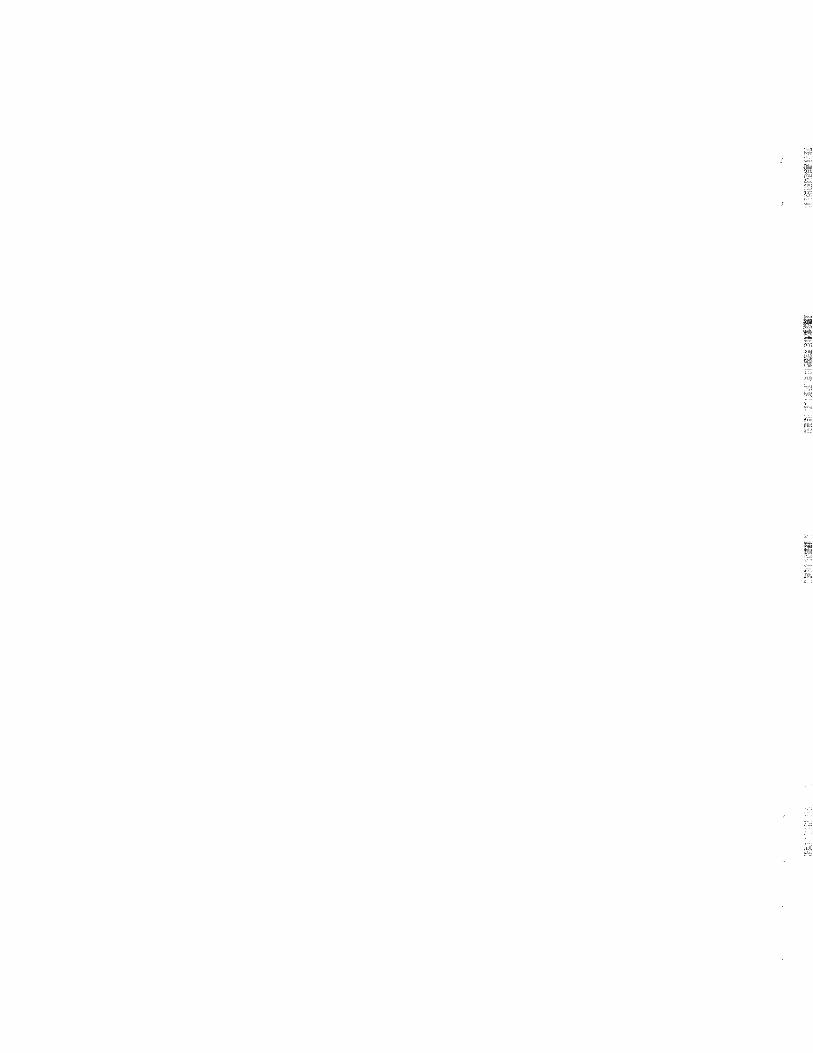
1.3 LOCATION
The S8ER F a c i l i t y was l o c a t e d a t the Rockwell I n t e r n a t i o n a l Energy Systems
Group Santa Susana F i e l d Labo ra to r i es (ESG/SSFL), which i s about 40 m i l e s no r th -
west of t he Los Angel es C i v i c Center (see F igu re 1).
F i gure 1. V i c i n i ty Map 00-1 0324A
(Courtesy o f Automobi 1 e C l ub o f Southern Cal i f o r n i a w i t h permiss ion)

The S8ER Fac i l i ty was an experimental reactor operation and tes t ing f a c i l i t y .
I t was b u i l t spec i f i ca l ly f o r small ( l e s s t an 2-f t diameter) compact- o r space-
type reactor t e s t ing and data co l l ec t ion a t full-power operation conditions.
2 . 1 PHYSICAL DIMENSIONS AND POWER RATING
The building was a r i g i d , steel-frame s t ruc tu re with corrugated metal s iding
and roofing with in ternal blanket thermal insula t ion. The foundation and f loor
were steel-reinforced concrete, The building was 60 f t long by 24 f t wide, with
a 17- f t eave height (see Figure 2 ) , The subsurface s t ruc tu re comprised three
s tee l - re inforced concrete vau l t s , of which two were a l so s tee l l ined. The maxi-
m u m depth was 14 f t below grade. All of the vaults were located in the reactor
room, which occupied the so thern 34 f t of the building.
The reactors were operated in the 3 - f t diameter, below-grade, concrete-
shielded reactor containment vessel vau l t . Reactors were supported from the
7704-62730
Figure 2. Buildin OiO Fac i l i ty Before S t a r t of Decommissioning
and removed without disassembly
or modification.
to less than 550
Support fac
The fixed-concrete shielding 7
kWt .
l i t i e s exter ior to the building
removable top shield plugs and could be inserted
i
imited the reactor power rating
consisted of equipment mounted
on small, grade-level concrete pads, and a buried radioactive gas holdup t a n k and drainage sump. The equipment consisted of e l ec t r i c transformers, a i r con-
di t ioners , exhaust gas stack and fans, and auxiliary coolers for the shield
cooling systems.
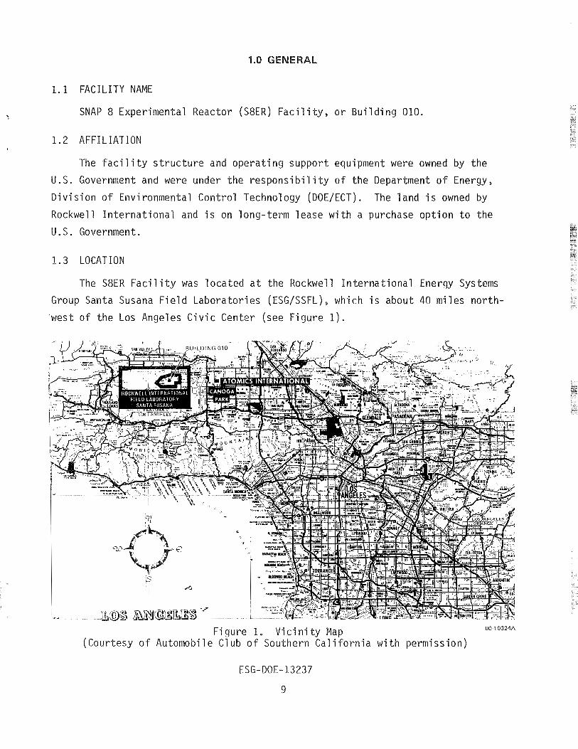
2 .2 SYSTEM DESCRIPTION
The original reactor development projects remove,d and disposed of the reac-
tors and supporting NaK systems for post-operation analysis before the conclusion
of the i r programs in 1965. The f a c i l i t y was l e f t in protective storage with some
surface contamination and the residual induced radioactivity confined in s i t u .
This radioactivity was shielded by the replacement of the concrete plugs and
covers that had been used during reactor tes t ing.
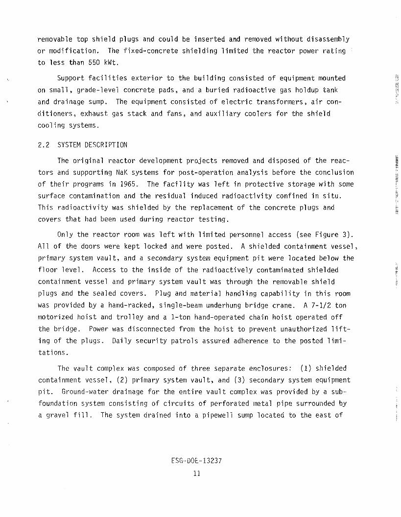
Only the reactor room was l e f t with limited personnel access (see Figure 3 ) .
All of the doors were kept locked and were posted. A shielded containment vessel,
primary system vault, and a secondary system equipment p i t were located below the
floor level. Access to the inside of the radioactively contaminated shielded
containment vessel and primary system vault was through the removable shield
plugs and the sealed covers. Plug and material handling capabili ty in th i s room
was provided by a hand-racked, single-beam underhung bridge crane. A 7-112 ton
motorized hoist and t rol ley and a 1-ton hand-operated chain hoist operated off
the bridge. Power was disconnected from the hoist to prevent unauthorized l i f t -
ing of the plugs. Daily security patrols assured adherence to the posted limi-
tations.
The vault complex was composed of three separate enclosures: (1) shielded
containment vessel, (2) primary system vault , and (3 ) secondary system equipment
p i t . Ground-water drainage for the en t i re vault complex was provided by a sub-
foundation system consisting of c i rcu i t s of perforated metal pipe surrounded by
a gravel f i l l . The system drained into a pipewell sump located to the east of
the building where the intercepted ground water could be monitored. The water
was then e i ther pumped into a tank for controlled disposal i f radioactive con-
tamination was detected, or discharged to the s i t e surface drainage system i f
no contamination was found.
The shielded containment vessel consisted of a 4-ft diameter by 14-ft high I carbon steel pressure vessel embedded in concrete. The domed upper head of the
containment vessel was removable and extended about 2 f t above the reactor room
floor . The exterior surface of the containment vessel was wrapped with two
coi ls of carbon s teel water cooling pipes. Two 6-in. diameter carbon steel
sleeves connected the upper compartment of the containment vessel with the pri-
mary system vault. Smaller penetrations of the containment vessel included:
two in l e t and out le t pipelines for control of vessel atmosphere, six shutdown
shield a i r cool ing pipe1 ines, two shield vent pipe1 ines, and four electr ical
and instrument conduits. All pipel ines and conduits were seal welded to the
containment vessel wall . The primary system vault consisted of a carbon s teel vault l iner 10 by 1 2
by 10 f t deep embedded in concrete. The top was equipped with movable concrete
shield plugs. Carbon s teel pipe cooling l ines were attached to the concrete
side of the s teel l iner . Various pipe sleeves connected the primary system
vault to the secondary system p i t and to the shielded containment vessel.
The secondary system equipment p i t was a small concrete vault. Steel floor
plates forming the top were a t the reactor room floor level. Connections to the
primary system vault were welded shut for protective storage isolation.
The t e s t f a c i l i t y was provided ventilation, heating, and a i r conditioning
in accordance with the specif ic requirements of the building areas. The systems
were separated into two major areas servicing the control room and the reactor
room. The reactor room was ventilated by a f i l t e red a i r exhaust system. Air
was drawn into the area through wall louvers and was exhausted through f i l t e r s
t o a fan, which discharged into the 50-ft f a c i l i t y stack. The exhaust fan and
related ductwork were located outside the building on a concrete pad.
The amount of radioactive waste produced by the t e s t reactor operation was
quite small; therefore, major waste collection or processing systems were not
JANUARY 25, MARCH 5, 1966 1969
LOCATION mR/h rnR/h
1 1 FILTER I 22.0 / 1.2 1 2 / COOLER I 1.0 1 0.1 1 3 PIPING
4 BACKGROUhD
5 PIPING
6 SURGETANK
7 HEATER 3.0 0.5 PRIMARY VAULT #14
8 F-61 FILTERS 9.0 / 1.0
9 PIPING 13.0 1 10 / OUTSIDE EAST WALL I 0.5 1 I 11 STACK FAN 4.4 1
13 / STACK INTAKE I 3.0 1 I I I I
TOP OF VAULT COVER 18.0
15 ON VAULT FLOOR (MAX) I 500.0
16 1 ON VAULT FLOOR (MINI 250.0 I I I
I INSIDE CONTAINMENT
120,000,0 VESSEL
8 1 BY FRONT DOOR I 0.07 / I INSTRUMENT THIMBLE
l9 #1 [TOP) 0.4
INSTRUMENT THIMBLE !O #2 (TOP) 80.0
INSTRUMENT THIMBLE l1 $3 (TOP) 0.4
INSTRUMENT THIMBLE $4 (TOP) 0.4
13 OUTSIDE SOUTH WALL 0.4
!4 OUTSIDE SOUTHWEST CORNER 0.2
INSIDE NORTHWEST '5 CORNER 0.1
!6 INSIDE ROOM 100 0.1
!7 N09THWEST CORNER BUILDING 010
0.1
!8 NORTHEAST CORNER BUILDING 010 1 .o
EMERGENCY GENERATOR,
REFRIGERATION EXCHANGER
MOTOR-GENERATOR -1 COOLER n F i g u r e 4. S8ER B u i l d i n g 010 R a d i a t i o n S u r v e y
prov ided f o r t h e f a c i l i t y . Small tanks were prov ided, however, f o r t he tem-
pora ry s torage o f bo th l i q u i d and gaseous wastes t h a t m igh t have been r a d i o a c t i v e .
Vent l i n e s t o t h e s tack exhaust f i l t e r s were prov ided f rom t h e containment
vessel and p r ima ry system v a u l t spaces and f rom those s e r v i c e systems capable of 3 producing a i r b o r n e r a d i o a c t i v i t y . A bur ied , 1 0 0 - f t gas holdup tank and a vacuum
i pump system were p rov ided t o pe rm i t ho ldup and mon i t o r i ng o f gases vented from
the p r imary hea t t r a n s f e r system f o l l o w i n g shutdown. The tank was p e r i o d i c a l l y
vented through t h e s tack f i l t e r s .
2.3 OPERATING HISTORY RELATING TO DECOMMISSIONING
A t the conc lus ion of t he S8ER experiment i n 1965, i t was in tended t o preserve
t h e f a c i l i t y f o r p o s s i b l e re-use t o t e s t f u t u r e compact r eac to r s . The S8ER
r e a c t o r and t h e spec ia l -purpose suppor t equipment ( i . e . , t he p r imary and secondary
sodium loops and c o n t r o l panels, e t c . ) were removed f rom the f a c i l i t y . Some sur-
face con tamina t ion was a l s o removed from the f a c i l i t y t o a l l o w u n r e s t r i c t e d ac-
cess t o most of t he b u i l d i n g . However, t h e p r imary v a u l t , which s t i l l had some
sur face contaminat ion, and t h e r e a c t o r containment vessel , which s t i l l had induced
r a d i o a c t i v e m a t e r i a l s , were covered w i t h t h e i r s h i e l d i n g b locks t o r e s t r i c t ac-
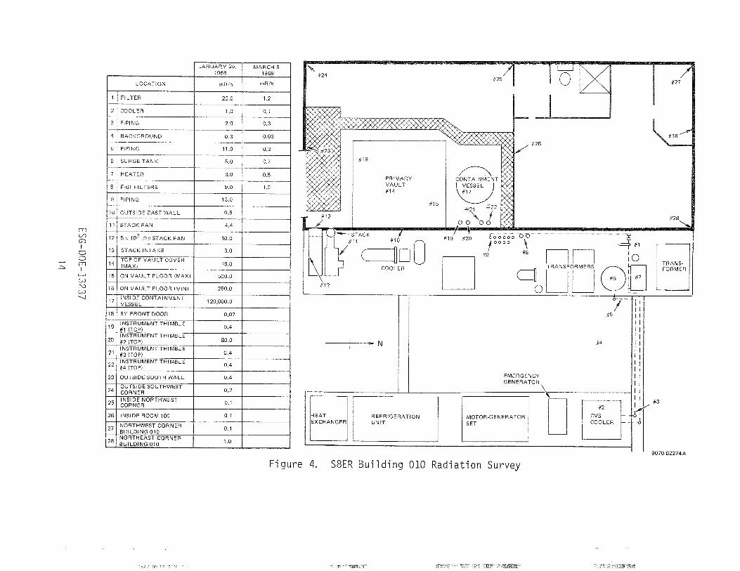
cess and t o s h i e l d t he remain ing r a d i a t i o n . The r a d i o a c t i v e con tamina t ion condi -
t i o n s a t t h a t t i m e a re shown i n F igu re 4.
The p lans f o r f a c i l i t y re-use d i d n o t m a t e r i a l i z e ; thus t h e b u i l d i n g r e -
mained r e l a t i v e l y unused f o r 9 years , and i t was f i n a l l y dec la red su rp lus i n
1974. I t was p laced i n a p r o t e c t i v e s to rage mode u n t i l r a z i n g s t a r t e d i n
September 1977.
A d e t a i l e d a n a l y s i s o f a c t i v a t i o n and con tamina t ion i s r epo r ted i n Sec t ion 5.
I t shows the l e v e l s o f r a d i o a c f i v i t y and i d e n t i f i e s t he s i g n i f i c a n t r ad ionuc l ides
expected t o be p resen t i n t h e neu t ron -ac t i va ted s t r u c t u r e s and components, i n -
c l u d i n g t he containment vessel , shutdown s h i e l d , o r d i n a r y concrete i n t h e reac-
t o r v a u l t s h i e l d i n g , r e i n f o r c i n g rods, i ns t rumen t th imb les , and c o o l i n g c o i l s .
2.3.1 Data Suppor t ing t he Presence of A c t i v a t i o n o r Contaminat ion
From ope ra t i ons logbooks and t he pub l i shed p r o j e c t documents, t h e f a c i l i t y
t o t a l ope ra t i ng h i s t o r y can be recons t ruc ted .
The reactor operati caused neutron activation of materials in the lower
half of the carbon steel contai ment vessel, in the surrounding materials in-
cluding some ear th, and in the s ta in less steel and concrete containment vessel
shield plug. The cumulative energy generated during reactor operation was
5 .4 x lo6 k W h t . These components were therefore exposed to a total neutron
f l uence correspo ing to th i s therm ergy generation.
s of the reactor contai ent vessel carbon steel cooling pipes were
a1 so in the though demi neral
a corrosion inhibitor was circulate
tamination was fou d in the f i l t e r s
cooling c i rcu i t s cont
ized water with hydrazine added as
closed loops, some radioactive con-
seal gland leakage. Therefore, i t
ained radioactive residue.
e primary vault cooli e same coolant as the reactor containment
so contained ra ioactive residues. A leak had occurred
in th i s system, maki g the concrete supporting structure suspect for radioactive
contamination.
The reactors were di sassembl e e primary vault with special remote
handling equipment. Although the vaults were subsequently decontaminated, some
radioactive materia adhered to the vault surfaces producing a radiation level
that would n o t have interfere with any future reactor tes t ing.
2 . 3 , 2 Speciaj .--. Data on Incidents That Could Be Significant to the Activation or tontamination
This was a well-operated f a c i l i t y that was, for the most part , f ree from
unplanned radioactlve material releases. Only two significant incidents are re-
- a leak in the shiel cooling water l ines under the vault f
another leak in the re inment vessel cooling l ines in the
the concrete shield. Both were repaired, and no extensive decontam
t o be required or performe
loor, and
earth near
ination was
3 . 1 NUCLEAR DESIGNER
The nuc lea r des ign work was performed by Atomics I n t e r n a t i o n a l ( A I ) [now
Energy Systems Group (ESG)] f o r t h e r e a c t o r systems operated i n t he f a c i l i t y .
3.2 FACILITY DESIGNER (A&E)
The s t r u c t u r a l and a r c h i t e c t u r a l des ign work was performed by Atomics
I n t e r n a t i o n a l (A1 ) . The f a c i 1 i ty was cons t ruc ted by a general c o n t r a c t o r under
t h e d i r e c t i o n o f A I .
3.3 DATE AND DURATION OF CONSTRUCTION
The S8ER Tes t F a c i l i t y was o r i g i n a l l y cons t ruc ted i n 1959 f o r the 50-kWt
SNAP 2 Experimental Reactor Tes t . Fo l l ow ing s a t i s f a c t o r y complet ion of t he
SNAP 2 t e s t i n 1960, t h e r e a c t o r and assoc ia ted t e s t equipment were removed f rom
t h e b u i l d i n g . I n 1961, improvements and m o d i f i c a t i o n s were made t o t h e f a c i l i t y
and equipment t o enable sa fe o p e r a t i o n o f t h e f a c i l i t y f o r a s i m i l a r t e s t i n g
program w i t h t h e h i ghe r power l e v e l 600-kWt SNAP 8 Experimental Reactor (S8ER).
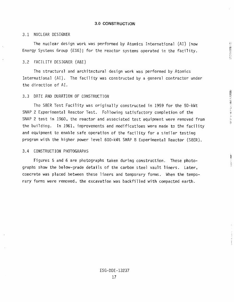
3.4 CONSTRUCTION PHOTOGRAPHS
F igures 5 and 6 a r e photographs taken d u r i n g cons t ruc t i on . These photo-
graphs show the below-grade d e t a i l s o f t he carbon s t e e l v a u l t l i n e r s . L a t e r ,
concre te was p laced between these l i n e r s and temporary forms. When t h e tempo-
r a r y forms were removed, t h e excava t ion was b a c k f i l l e d w i t h compacted e a r t h .
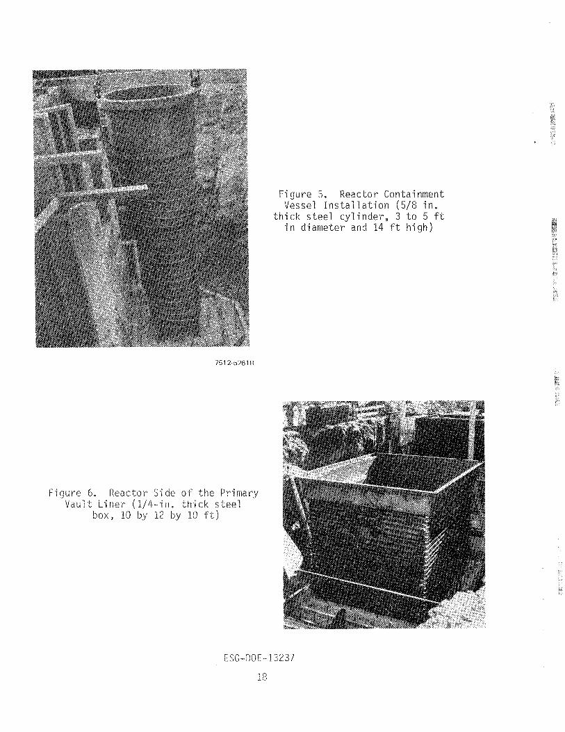
Figure 5. Reactor Containment Vessel Ins ta l 1 ation (5/8 in.
thick s tee l cylinder, 3 t o 5 f t in diameter and 14 f t high)
Figure 6, Reactor Side o f the Primary Vault Liner (1/4-in, thick s t e e l
ox, 10 by 12 by 10 f t )
The o b j e c t i v e o f t he B u i l d i n g 010 (S8ER) f a c i l i t y decommissioning was t o
p lace the area i n a c o n d i t i o n f o r u n r e s t r i c t e d use by removing a l l r a d i o a c t i v e
contaminat ion t o below the l e v e l s t h a t would r e q u i r e any r a d i o l o g i c a l s u r v e i l - lance and l i c e n s i n g .
4.1 MODE
A d ismant l ing mode was se lec ted as the sa fes t and most c o s t - e f f e c t i v e ap-
proach t o decommissioning. The d r i v i n g f e a t u r e was t h a t more than h a l f of the
b u i l d i n g and foundat ion would be razed j u s t t o gain access t o t he below-grade
concrete v a u l t s and a c t i v a t e d ear th . Any p ro jec ted use f o r t he b u i l d i n g would
n o t j u s t i f y t he r e s t o r a t i o n and remodeling costs .
4.2 REGULATORY REQUIREMENTS
4.2.1 Governing Regulatory Agencies
The use o f r a d i o a c t i v e m a t e r i a l s i n C a l i f o r n i a i s l icensed and regu la ted by
the U.S. Nuclear Regulatory Commission (NRC) i n the case o f spec ia l nuc lear mate-
r i a l s , o r by the Stake o f C a l i f o r n i a , Department o f Hea l th i n t he case o f source
and byproduct ma te r i a l s . U.S. Government owned o r c o n t r o l l e d f a c i l i t i e s are
exempt from l i c e n s i n g when the re i s demonstrated government use o r need. When
DOE i s t he respons ib le agency, the DOE Operations Manual prov ides guidance and
d i r e c t i o n .
I n d u s t r i a l s a f e t y requirements a t ESG-owned f a c i l i t i e s are de f ined by the
Cal i f o r n i a Occupational Safety and Heal t h Admin i s t ra t i on (OSHA) regu la t i ons , as
adminis tered by the C a l i f o r n i a Department o f Occupational Safety and Health.
I n d u s t r i a1 s a f e t y requirements a t DOE-owned f a c i 1 i t i e s a re de f ined by DOE Imme-
d i a t e Ac t i on D i r e c t i v e No. 0504-33, as adminis tered by DOE-OES.
4.2.2 L icens ing Requirements
The o b j e c t i v e was t o have the s i t e a v a i l a b l e f o r general access and f r e e o f
a l l s u r v e i l l a n c e and c o n t r o l requirements. The performance o f the decommissionin
was dur ing the p e r i o d when the s i t e was under f ede ra l government c o n t r o l and exempt
f rom fede ra l and s t a t e l i c e n s i n g r e g u l a t i o n s . Th i s s t a t u s w i l l extend as l o n g as
t he l and i s U.S . Government c o n t r o l l e d ; however, i n t he event t he op t ioned l a n d
were t o r e v e r t t o ESG, t h e s t a t e r e g u l a t i o n s would apply . For t h i s reason, t h e
f a c i l i t y and l a n d must be decontaminated t o a l e v e l t h a t i s p r o j e c t e d t o be
acceptable t o the S ta te o f C a l i f o r n i a f o r an un l i censed area.
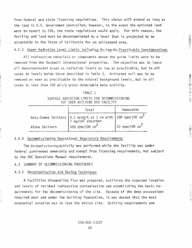
4.2.3 Upper R a d i a t i o n Level L i m i t s I n c l u d i n g As-Low-As-Practicable Cons idera t ions
A l l r a d i o a c t i v e m a t e r i a l s o r components above t h e gu ide l i m i t s were t o be
removed f rom t h e Rockwell I n t e r n a t i o n a l p rope r t i es . The o b j e c t i v e was t o 1 eave
a l l decontaminated areas a t r a d i a t i o n l e v e l s as low as p r a c t i c a b l e , b u t i n a l l
Z cases t o l e v e l s below those descr ibed i n Table 1. A c t i v a t e d s o i l was t o be
removed as near as p r a c t i c a b l e t o t h e n a t u r a l background l e v e l s , b u t i n a1 1
cases t o l e s s than 100 pCi /g gross de tec tab le beta a c t i v i t y .
TABLE 1
SURFACE RADIATION LIMITS FOR DECOMMISSIONING THE S8ER BUILDING 010 FACILITY
To ta l I Removable
Beta-Gamma Emi t t e r s 10.1 mracj/h a t 1 cm w i t h 1100 dpm/100 cm 2
A1 pha Emi t t e r s
7 mg/cmZ absorber
100 dpm/100 cm2
4.2.4 Decommissioning Opera t iona l Regulatory Requirements
The decommiss ion ingac t i v i t y was performed w h i l e the f a c i l i t y was under
federa l government ownership and exempt f rom l i c e n s i n g requirements, b u t s u b j e c t
t o t he DOE Operat ions Manual requirements.
4.3 SUMMARY OF DECOMMISSIONING PROCEDURES
4.3.1 Decontaminat ion and Razing Techniques
A Faci l i t i e s D ismant l ing Plan was prepared, ou t1 i n i n g t h e expected l o c a t i o n
and l e v e l s o f r e s i d u a l r a d i o a c t i v e con tamina t ion and e s t a b l i s h i n g t he bas i c r e -
quirements f o r t he decommissioning of t h e s ide . Because o f t h e deep excavat ions
r e q u i r e d near and under the b u i l d i n g foundat ion , i t was deemed t h a t t h e most
economical s o l u t i o n was t o raze t h e e n t i r e s i t e . A c t i v i t y requirements and
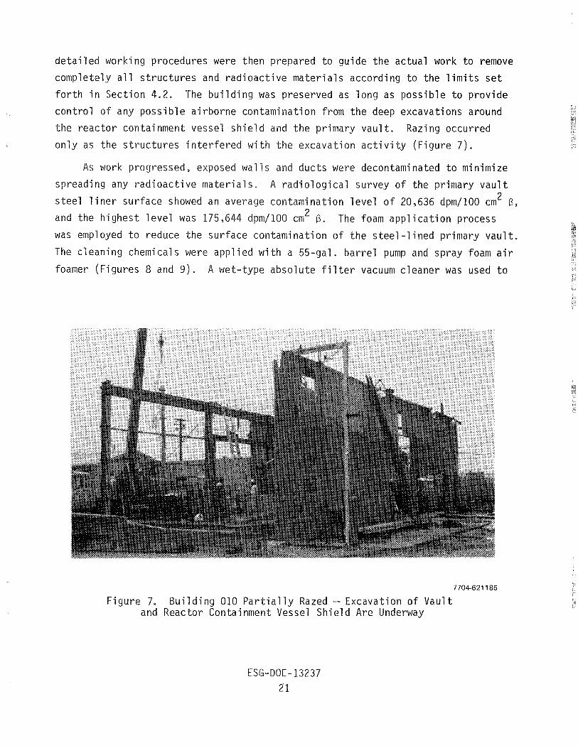
deta i led working procedures were then prepared to guide the actual work to remove
completely a l l s t ruc tu res and radioactive materials according to the l imi t s s e t
for th in Section 4.2. The building was preserved as long as possible to provide
control of any possible airborne contamination from the deep excavations around
the reactor containment vessel shie ld and the primary vault . Razing occurred
only as the s t ruc tu res in terfered with the excavation ac t i v i t y (Figure 7 ) .
As work progressed, exposed walls and ducts were decontaminated t o minimize
spreading any radioactive materials . A radiological survey of the primary vaul t 2 s t ee l l i n e r surface showed an average contamination level of 20,636 dpm/100 cm B,
2 and the highest level was 175,644 dpm/100 cm B. The foam applicat ion process
was employed t o reduce the surface contamination of the s tee l - l ined primary vaul t .
The cleaning chemical s were applied with a %-gal . barrel pump and spray foam a i r
foamer (Figures 8 and 9 ) . A wet-type absolute f i l t e r vacuum cleaner was used t o
7704-621 185
Figure 7. Building 010 Pa r t i a l l y Razed - Excavation of Vault and Reactor Containment Vessel Shield Are Underway
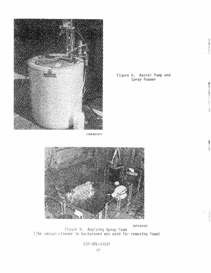
ure 8. Barrel Pump and Spray Foamer
9070-62182
r removing foam)

remove t he c l ean ing chemicals a f t e r a hand scrubbing ope ra t i on (F igures 9 and 10) .
The scrubbing was r e q u i r e d t o l i f t sca le o r porous adherents. A f t e r two app l i ca -
t i o n s o f t he foaming process, t h e average surface contaminat ion was g e n e r a l l y
reduced severa l o rders of magnitude; t h e h i g h e s t area was reduced f rom 175,644 2 t o 21,000 dpm/100 cm B.
Fo l l ow ing t h e foam process, t h e v a u l t w a l l s were pa in ted w i t h a f i x a t i v e and
were c u t f r ee of the r e a c t o r containment vessel s h i e l d w i t h t h e Hy Ram (F igu re 11).
The remain ing v a u l t w a l l s and f l o o r were broken i n t o l a r g e p ieces f o r d isposa l
w i t h o u t t o r c h c u t t i n g .
The r e a c t o r containment vessel , i t s i n t e r n a l ins t rument th imb les , and
at tached concre te s h i e l d were removed and shipped as a u n i t t o take f u l l advan-
tage of the e x i s t i n g s h i e l d (F igures 12 and 13) . The t o t a l we igh t of t h i s p iece
was 97 tons. Th i s we igh t and t h e 8 - f t w i d t h r e q u i r e d highway t r a n s p o r t a t i o n
permi ts f o r C a l i f o r n i a and Nevada. An e x t r a c o u r i e r v e h i c l e was used behind t he
l oad t o g i v e added assurance of m in im iz i ng t h e p o t e n t i a l o f develop ing problems
en rou te .
The lower h a l f of t h e excavat ion, be fo re t h e vessel and s h i e l d were removed,
had readings of 300 t o 500 mrad/h, By on a Juno Meter. A f t e r t h e vessel and con-
c r e t e were removed, t h e r a d i a t i o n f rom t h e s o i l i n t h e p i t was recorded as
20,000 cpm w i t h a pancake G-M probe and 10 mrad/h, By. The r a d i a t i o n read ing on
the lower 3 ft of t he concre te was approx imate ly 100 mrad/h, By a t 18 i n . , and
up t o 400 mrad/h, By a t spots . The concre te was ~ r a p p e d ~ w i t h p l a s t i c shee t ing
and shipped f rom t h e s i t e f o r b u r i a l . The excava t ion was en la rged a f t e r t he
concrete was removed t o ensure t h a t a l l r a d i o a c t i v e m a t e r i a l s above t h e r a d i a t i o n
l i m i t s shown i n Sec t ion 4.2 were removed (F igu re 14) . Imported new sand and non-
contaminated concre te r u b b l e from t h e s i t e were used t o b a c k f i l l a l l excavat ions
t o t he o r i g i n a l grade.
The r a z i n g techniques f o r t h e non rad ioac t i ve o r decontaminated s t r u c t u r e
were convent iona l disassembly and salvage o f t h e main members. Minor noncon-
taminated components were s o l d f o r scrap. Contaminate m a t e r i a l n o t found t o be
economical t o decontaminate ( f o r example t he waste gas holdup tank show
F igure 15) was boxed and shipped t o t h e d isposa l s i t e .

9070-621 81
Figure 10. Vacuuming Spray-Foamed and Scrubbed a l l Surface
7704-621 210
ure 11. Breaking Co c r e t e With a Hydraulic Hy Rani Attached t
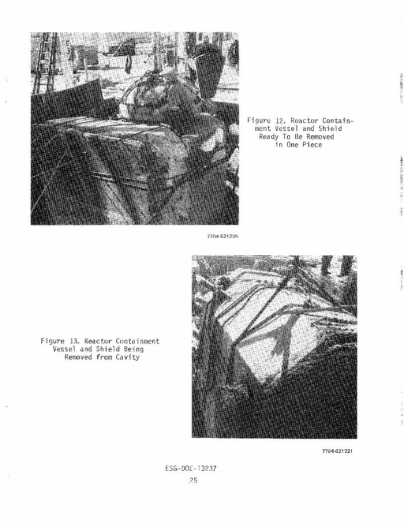
Figure 12. Reactor Contain- ment Vessel and Shield Ready To Be Removed
in One Piece
Figure 13. Reactor Containment Vessel and Shield Being
Removed from Cavity
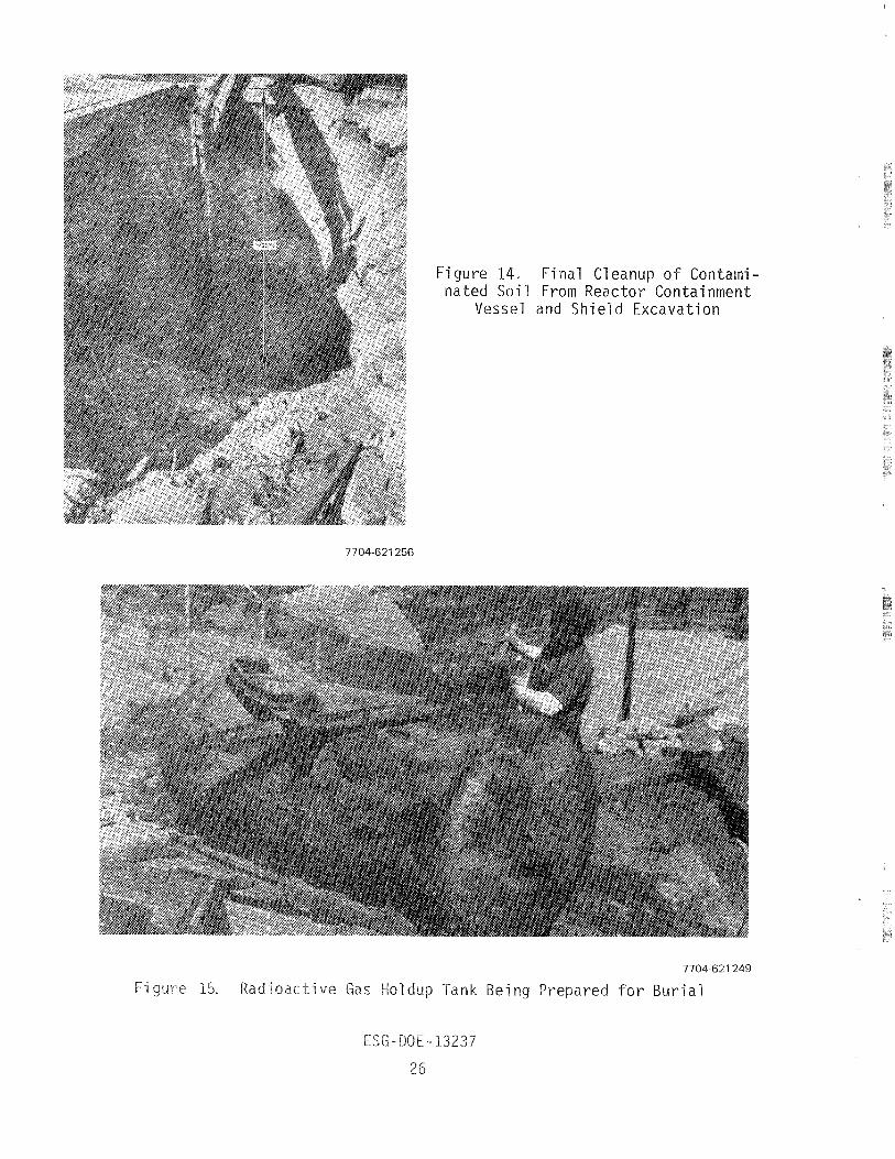
Figure 14. F ina l Cleanup o f Contami- n a t e d S o i l From Reac to r Containment
Vessel and S h i e l d Excavat ion
7704621 249
a c t i v e Gas Hol u p Tank Being Prepared f o r B u r i a l
4.3.2 Special Tooling, Equipment, or Techniques Required
No unique equipment was used. The concrete-breaki ng (Figure 11) and hoisting
equipment used were the largest commercial s ize locally available. The rental of
th i s equipment from commercial sources allowed the planned removal of large pieces
to proceed with dispatch and relat ive ease.
4.3.3 Special Access or - Si te Problems Affecting Decommissioning
The Building 010 s i t e was in the midst of operating nonradioactive f a c i l i -
t i e s . There was no interruption of the ac t iv i t i e s in these f a c i l i t i e s as a resu l t
of the decommissioning ac t iv i ty a t the Building 010 s i t e . This was due in large
part to the small s ize of the building and the relatively large surrounding paved
area. The work area had a temporary fence erected around i t , and the fenced area
was posted to r e s t r i c t access to that necessary for the project.
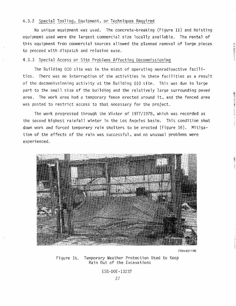
The work progressed through the Winter of 1977/1978, which was recorded as
the second highest ra infal l winter in the Los Angeles basin. This condition shut
down work and forced temporary rain she1 t e r s to be erected (Figure 16). Mi t iga-
tion of the effects of the rain was successful, and no unusual problems were
experienced.
Figure 16. Temporary Weather Protection Used to Keep Rain O u t of the Excavations
4 .4 S U B S E Q U E N T F A C I L I T Y U S E P L A N S
The s i t e i s to be used as a parking l o t . Eventually, there could be a new
structure erected on the s i t e suitable for unrestricted use.
TIVITY STATUS
5.1 PRE-DECOMMISSIONING CURIE INVENTORY OF ACTIVATED STRUCTURE, MATERIALS, AND EQU I PMENT
Total ac t iv i ty expected to be present in the various activated structures
was calculated on the basis of the total weight of each structure in the cases
of the containment vessel, cooling co i l s , s ta inless s t e e l , and reinforcing rods.
In the case of ordinary concrete, the total ac t iv i ty present was evaluated on
the basis of the volume of concrete present to the depth of one relaxation length
for thermal neutrons over the total surface exposed to the neutron flux. No
evaluation of total ac t iv i ty was performed in the cases of the s ta in less steel
and high-density concrete, as both materials were in portable plugs and thimbles.
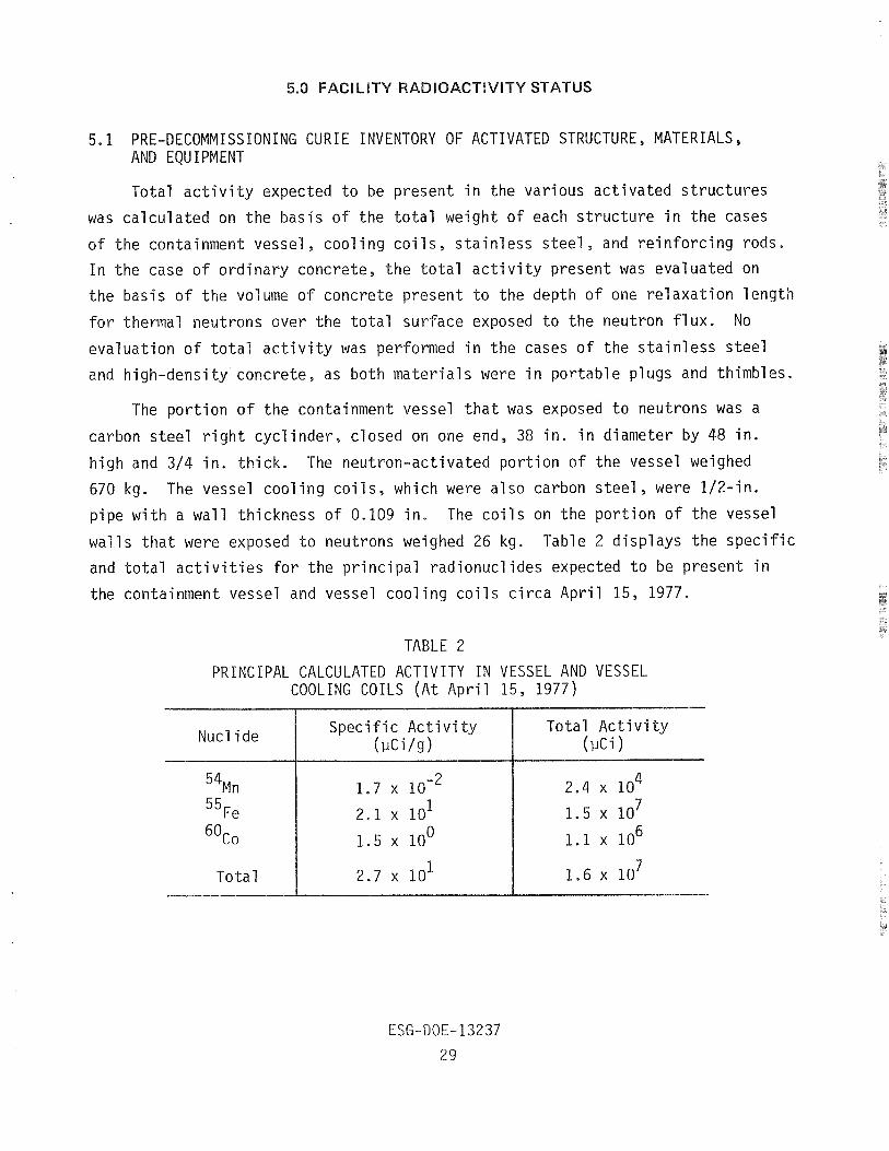
The portion of the containment vessel tha t was exposed to neutrons was a
carbon steel r ight cyclinder, closed on one end, 38 in . in diameter by 48 in .
h i g h and 314 in. thick. The neutron-activated portion of the vessel weighed
670 kg. The vessel cooling coi l s , which were also carbon s t e e l , were 112-in.
pipe with a wall thickness of 0.109 in. The coi ls on the portion of the vessel
walls that were exposed to neutrons weighed 26 kg. Table 2 displays the specific
and total ac t iv i t i e s for the principal radionuclides expected to be present in
the containment vessel and vessel cooling coi ls circa April 15, 1977.
TABLE 2
PRINCIPAL CALCULATED ACTIVITY IN VESSEL A N D VESSEL COOLING COILS ( A t April 15, 1977)
Total I 2.7 x 10 1 1 1.6 x 10⁷
Nucl i de Specific Activity Total Activity ( ~ l c i / s )
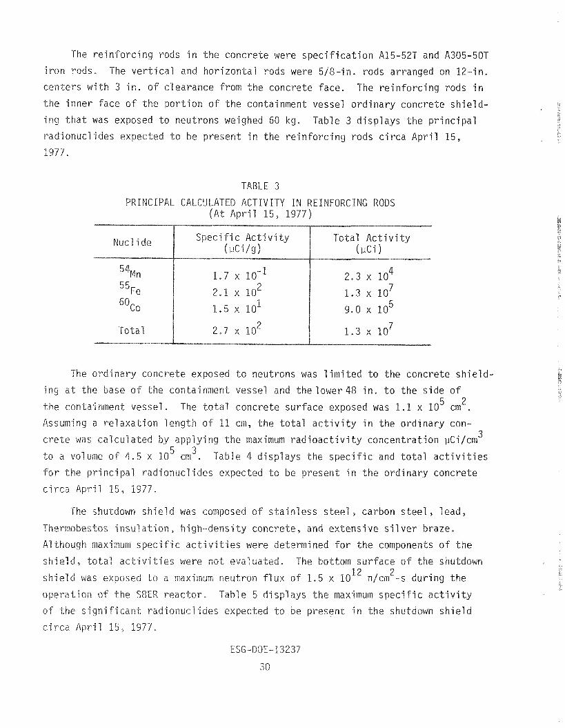
The reinforcing rods in the concrete were speci f ica t ion A15-52T and A305-50T
on rods. The ver t ica l and horizontal rods were 518-in. rods arranged on 12-in.
centers with 3 in . of clearance from the concrete face. The reinforcing rods in
the inner face of the portion of the containment vessel ordinary concrete shie ld-
t ha t was exposed t o neutrons weighed 60 kg. Table 3 displays the principal
ionuclides expected t o be prese t in the reinforcing rods c i rca April 15,
T A B L E 3
CIPAL CALCULATED ACTIVITY IN REINFO ( A t April 15, 1977)
Nucl i de Specif ic Activi ty Total Activi ty ( u w g )
5 4 ~ n
5 5 ~ e
6oco
Total
The ordinary concrete ex osed t o neutrons was l imited t o the concrete shie ld-
a t the base of the containment vessel and thelower48 in . t o the s ide of 5 2 the containment vessel . The t o t a l concrete surface exposed was 1 .1 x 10 cm .
Assuming a relaxation length of 11 cm, the to ta l a c t i v i t y in the ordinary con-
c r e t e was calculated y applying the maximum rad ioac t iv i ty concentration p~i/crn' 5 3 a volume of 4 ,5 x 10 cm . Ta 7e 4 displays the spec i f i c and t o t a l a c t i v i t i e s
r incipal radi nuclides expected t o be present in the ordinary concrete
c i rca April 15, 1977.
shield was composed of s t a i n l e s s s t e e , carbon s t e e l , lead,
concrete, and extensive s i l v e r braze.
pec i f i c a c t i v i t i e s were determined f o r the components of the
ottom surface of 2 x n/cm -s
e maximum spec i f i c a c t i v i t
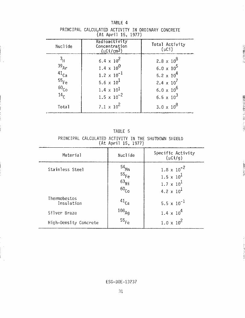
TABLE 4 PRINCIPAL CALCULATED ACTIVITY IN ORDINARY CONCRETE
(At April 15, 1977)
Radioacti vi t y Concentration
, ( u ~ i / c m 3 )
6.4 x 10 2
1.4 x loo
Total Ac t iv i ty ( N i 1
TABLE 5
PRINCIPAL CALCULATED ACTIVITY IN THE SHUTDOWN SHIELD (At April 15, 1977)
S t a i n l e s s S tee l
Thermobestos Insula t ion
Si 1 ver Braze
High-Densi t y Concrete
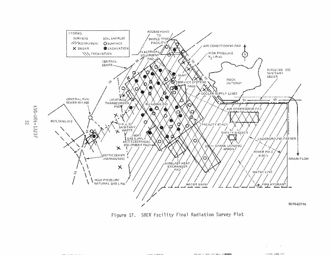
Figure 17 . S8ER F a c i l i t y Final Radiation Survey Plo t

The ins t rument t h i m b l e l i n e r s were s t a i n l e s s s t e e l . Table 6 d i s p l a y s t he
maximum s p e c i f i c a c t i v i t y o f t h e s i g n i f i c a n t r ad ionuc l i des expected t o be p resen t
c i r c a A p r i l 15, 1977.
TABLE 6
PRINCIPAL CALCULATED ACTIVITY I N STAINLESS STEEL INSTRUMENT
THIMBLES ( A t A p r i l 15, 1977)
A r a d i a t i o n measurement taken a t t he bottom o f an ins t rument t h imb le d u r i n g
October o f 1977 i n d i c a t e d a maximum r a d i a t i o n l e v e l o f 60 Rih. The major source
of t h i s gamma r a d i a t i o n appeared t o be t he a c t i v a t e d s t a i n l e s s s t e e l i n t h e
th imb les and t h e f ace o f t h e shutdown s h i e l d .
Nucl i d e
5.2 DECOMMISSIONING RADIOLOGICAL SURVEY OF BUILDINGS, INTERIORS, AND SUPPORT SYSTEMS
S p e c i f i c A c t i v i t y ( u c i / g )
Two pos t -ope ra t i on surveys were conducted - one as t h e f a c i l i t y was be ing
re leased f rom the r e a c t o r ope ra t i on p r o j e c t f o r o t h e r a c t i v i t i e s and one severa l
years l a t e r as r o u t i n e s u r v e i l l a n c e . These two surveys a re shown on F igure 4.
Surveys f o r t h e f i n a l decommissioning work were made as t he work progressed.
The e s s e n t i a l survey p o i n t s a r e recorded i n F igu re 17.
P r i o r t o b a c k f i l l i n g t h e excavat ions, approx imate ly 200 smear samples were
taken on t h e concre te r u b b l e and underground plumbing, i n c l u d i n g t h e s a n i t a r y
sewer l e a d i n g t o t h e abandoned l each f i e l d , t h a t was t o remain on t h e s i t e . 2 A l l r e s u l t s were documented a t l e s s than 50 dpm/100 cm 8. A l l smears were
counted f o r a and B a c t i v i t y on a Nuclear Measurements Corpora t ion automat ic
coun t ing system, w i t h an average background count o f 25 cpm i n t h e 6 channel and
a coun t ing e f f i c i e n c y f a c t o r o f 2.35 dpm/cpm f o r B. The e f f i c i e n c y f a c t o r
he net count r a t e f o r geometric an e lec t ron ic detection eff ic iency
amination was not suspected fo r t h i s
ver , had any o , i t would have been detected with t h i s automatic
counting system.
material sam es were counted on a Nuclear Chicago automatic counting
system with a KC1 s t a ackground of 20 counts per m i
s o i l originated from below 10 f t deep along the s ides of
etow the primary vaul t . The contaminated concrete
e f l oo r and lower s i es of the primary system vaul t . Concrete
from a portion of the primary system vaul t wall. All
samples were l e s s than 50 pCi/g gross 6. The ven t i l a t ion stack and some other
reactor support system uried piping had the highest level of radioactive con- 2 Smear samp icated 2500 dpm/100 cm maximum removable beta
a c t i v i t y .
During the dismantling and excavation a c t i v i t i e s , water and a i r samples
were collected fo r analys is and detection of radioact iv i ty . The r e su l t s were
sed t o assure the safe ty of the workers and t o monitor the discharge of e f f luen t s .
Water was co l l e c t e from the sump drain system and vessel p i t where ra in water
accumulated. Air was col lec ted by a continuous a i r sampler located in the im-
mediate v i c in i t y of the work area , and was per iodical ly examined f o r any col lec-
of radioactive material .
None of the water samples indicated over 4 .5 x lo-* pCi/ml, 6, which i s well
elow the l im i t of 3 x pCi/ml , 6 f o r strontium-90 in water released in u n -
r e s t r i c t ed areas . T samples were evaporated t o about 10 ml on a hot-
nd then dried ted counting planchette. An automatic counting
an average background of 20 cpm an 2,59 dpm/cpm eff ic iency f ac to r
was used t o measure t o water samples were collected a t the con-
o water remaining a t the f a c i l i t y
s i t e .
airborne radioactive par t i cu la te concen-
occurrf ng airborne rad ioac t iv i ty , exceeding
1 below the MPC f o r c bal t-60, 3 x 10-lo uCi/ml ,
fi-y in unres t r ic ted areas. The samples were collected on f i l t e r s in a vacuum
a i r sampler located in the immediate v i c in i t y of the decommissioning workers. 3 Air was drawn through the f i l t e r a t approximately 3 f t /h. Each sample com-
3 prised the f i l t r a t e from 2 t o 20 f t of a i r , depending on the potential exposure
and duration of the work. The f i l t e r with the captured material was immediately
placed in a P, y counter f o r a radia t ion measurement. Delayed counting 24 h
l a t e r showed a normal background decay t o 0.1 to 0.01 of the immediate count.
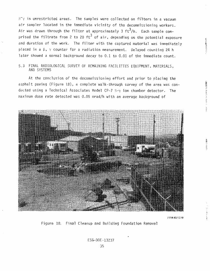
5 . 3 FINAL RADIOLOGICAL S U R V E Y OF REMAINING FACILITIES EQUIPMENT, MATERIALS, A N D SYSTEMS
A t the conclusion of the decommissioning e f f o r t and pr ior t o placing the
asphalt paving (Figure 18 ) , a complete walk-through survey of the area was con-
ducted using a Technical Associates Model CP-7 6-y ion chamber detector . The
maximum dose r a t e detected was 0.05 mradlh with an average background of
7704-621 279
Figure 18, Final Cleanup and Building Foundation Removal
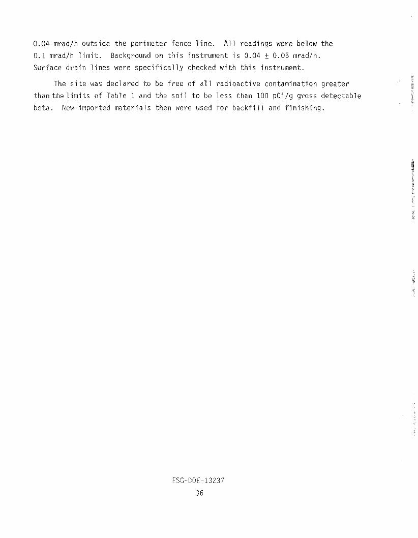
0.04 mrad/h outside the perimeter fence l i ne . All readings were below the
0.1 mrad/h l i m i t . Background on t h i s instrument i s 0.04 4 0.05 mrad/h.
l ines were spec i f i c a l l y checked with t h i s instrument.
The s i t e was declared to be f r e e of a l l radioactive contamination greater
than t h e l i m i t s of Table 1 and the so i l t o be l e s s than 100 pCi/g gross detectable
beta. New importe materials then were used fo r backfi l l and f in ishing.
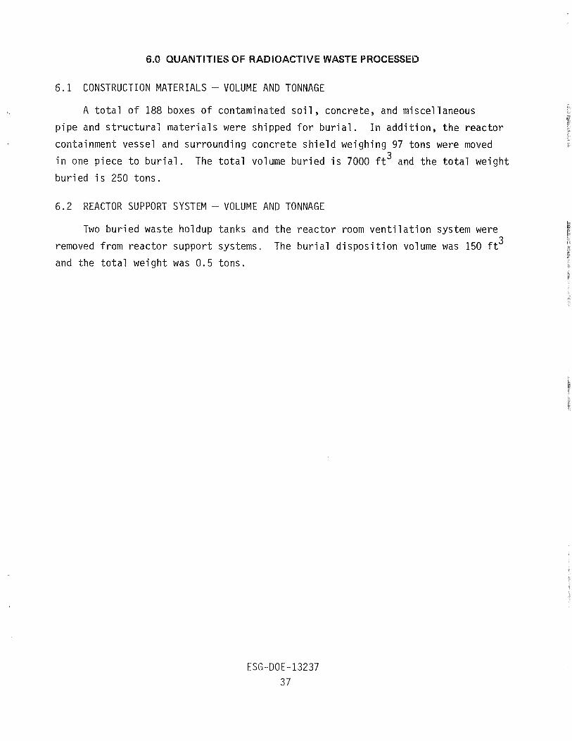
6.1 CONSTRUCTION MATERIALS -
A t o t a l o f 188 boxes o f
p i p e and s t r u c t u r a l m a t e r i a l s
- VOLUME AND TONNAGE
contaminated s o i l , concrete, and misce l laneous
were shipped f o r b u r i a l . I n a d d i t i o n , t h e r e a c t o r
containment vessel and surrounding concre te s h i e l d weigh ing 97 tons were moved 3 i n one p iece t o b u r i a l . The t o t a l volume b u r i e d i s 7000 f t and t h e t o t a l weight
b u r i e d i s 250 tons .
6.2 REACTOR SUPPORT SYSTEM - VOLUME AND TONNAGE
Two b u r i e d waste ho ldup tanks and t h e r e a c t o r room v e n t i l a t i o n system were
removed f rom r e a c t o r suppor t systems. The b u r i a l d i s p o s i t i o n volume was 150 f t 3
and the t o t a l we igh t was 0.5 tons.
7704-621 254
Packaging f o r
IAL
7.1 LOW SPECIFIC ACTIVITY (LSA) AND HIGH SPECIFIC ACTIVITY (HSA) TRANSPORTATION AND BURIAL COST
There was only LSA material t o be disposed o f , a s the reactor and associated
contaminated equipment had been removed and disposed of several years e a r l i e r ,
before the f a c i l i t y was declared surplus t o program needs.
All loose contaminated material was boxed and transported by commercial
truck t o the licensed NECO burial s i t e a t Beatty, Nevada. The reactor contain-
ment vessel and shie ld were wrapped with p l a s t i c sheeting and tarpaul ins f o r
the trip.
The cost of burial a t Beatty was increased s ign i f i can t ly during t h i s proj-
e c t from $2.65/ft3 t o $3.85/ft3. The containment vessel was buried a t the
higher r a t e .
The cost of t ranspor ta t ion was approximately $653 t o $775 per t r i p with a
20-ton load. The one ex t ra wide and heavy load of the shie ld and vessel cos t
$31,127, including the crane service fo r loading and unloading and the wide load
escor t service.
7.1.1 Special Packaging Costs
The packaging was standardized as much as possible (Figures 19 and 20).
The standard box i s a knockdown, corrugated-cardboard, double-wall container
t h a t wil l contain 33 f t " . This i s 1 ined with a p l a s t i c bag and banded fo r
added strength. The f i l l e d box i s banded f o r closure. Each box costs $30 t o
produce. Several l a rge r special boxes were prepared f o r odd-shaped s t ruc tu res .
Their cos t i s estimated a t $100 each. The wrapping of the containment vessel
and attached concrete shie ld involved placing some ex t r a , temporary lead shie ld-
ing on the s ides and wrapping the complete item with p l a s t i c sheeting. The t o t a l
cos t of the extra shielding and shipping protection i s estimated a t $3000, in-
cl udi ng l abor and material s .
7.2 DISPOSITION SITE
The disposi t ion s i t e f o r a l l radioactive waste taken from the Building 010
s i t e i s the NECO S i t e a t Beatty, Nevada (Figure 2 1 ) . I t i s operated by Nuclear
Engineering Company under a S ta te of Nevada l icense .
E L
8.1 TOTAL MAN-REM FOR PROJECT
The group of people working on the S8ER Facili ty decommissioning project
varied in composition as particular ta lents and personnel ava i lab i l i ty from
other similar assignments permitted. Over the period of project duration, the
total group exposure was 2.3 man-rem.
Packaging, handling, and warehousing radioactive waste materials a t the
nearby RMDF i s not included in the above total exposure because the operation
involves simultaneous exposure to radioactive waste from several projects.
fl The RMDF exposure due to processing the large reactor containment vessel
shield can be estimated, however, because i t was not mixed with other waste and
was shipped separately. The preparation for shipment, which included placing
temporary lead shielding and wrapping i t with plast ic sheeting, i s estimated to
increase the total exposure by 0.75 man-rem. The shield was warehoused for
6 months a t the RMDF because of some non-project-related shipping delays. During
t h i s time normal operations not associated with th i s project that were conducted
nearby had an estimated increased exposure from the shield source of another
0.5 man-rem. The added exposure that was incurred by loading the shield onto the
truck and monitoring the shipment i s estimated to increase the total exposure by
another 0.96 man-rem.
Including a l l of these ac t iv i t i e s together, the total estimated exposure
would be 4.5 man-rem.
8.2 M A X I M U M INDIVIDUAL DOSE
The maximum integrated dose received by an individual assigned t o the proj-
ec t over the time of active decommissioning was 660 mrem from a l l sources.
8.3 AVERAGE INDIVIDUAL DOSE
The average individual dose for a l l workers assigned to the decommissioning
roject , exclusive of supervision and other nonexposed personn I , was 140 mrem as
read from external dosimeters. Including the estimated RMDF exposure will in-
crease the average individual dose to 180 mrem. The routine bioassay of a l l
workers assigned to th i s project showed negligible internal exposure.
The S8ER Facili ty decommissioning program followed guidance contained in
ERDA (now D O E ) Manual Chapter 0524 for radiological safety and for maintaining
personnel exposure t o as low as practicable ( A L A P ) . This overall plan was im-
plemented for the specific task of Building 010 decommissioning in the ESG
e Energy Systems G ager of Health, Safety, an
was responsible for establ ishing standards of safety, examining proposed
azards, determining the safety measures tha t were necessary, and
ing the degree of comp iance with safety measures, contract safety re-
nts , l icenses, and regulations. Members of the HS&RS s t a f f prepared an
Operational Safety Plan in support of the decommissioning program, reviewed a l l
perational procedures documentation, and provided day-to-day health physics and
ygiene and sa surveillance of program ac t iv i t i e s . They also
ersons assigned to work in the radiologically
a t these persons were fu ly qualified "radiation
i l i a r i tywi th the operations in the posted areas
to work safely in these areas.
Since a decommissioning program i s a ser ies of nonroutine a c t i v i t i e s , pri-
rotection was provided by continuous monitoring of radiation exposures and
ination, and y a continuing review and evluation of the individual act ivi-
t i e s to minimize potentia exposures to radiation and radioactive contamination.
r i t t en plans for t e decommissioning had detailed reviews, incl uding con-
sideration of various appro es and the i r effectiveness in minimizing radiation
. These reviews co dered working times, the radio1 ogical hazards in-
and the proper use of protective clothing, shielding, and remote handling
t , although no remote ha dl ing was ernpl oyed.
Facili ty equipme a s necessary ventilation, cool ing, a
systems, were checked prior had continuing surveil ance to ensure
d , as require by the operations unde
t e , the use of area a i r sam
r a d i a t i o n and contaminat ion surveys. Mon i t o r i ng and p r o t e c t i v e equipment was
des ignated as necessary and i nc l uded personal f i l m badges, spec ia l badges f o r
tasks w i t h p o t e n t i a l h i gh exposure r i s k (processed a t s u i t a b l e i n t e r v a l s ) , pro-
t e c t i v e c l o t h i n g app rop r i a te t o t he work ing cond i t i ons , and r e s p i r a t o r s chosen
accord ing t o t h e hazard.
Dosimetry r e s u l t s , as recorded by f i l m badges and b ioassay data, and
r a d i a t i o n and con tamina t ion surveys were eva lua ted t o determine p o s s i b l e means
of improv ing t he c o n t r o l procedures and t o ensure maintenace o f exposures t o
as low as p r a c t i c a b l e .
For opera t ions i n areas i n which c o n d i t i o n s were n o t changing, r a d i a t i o n
l e v e l s were posted. I n most ins tances, however, t he r a d i a t i o n l e v e l changed
s i g n i f i c a n t l y d u r i n g t h e course o f t he work and was moni tored f r e q u e n t l y .
Procedures f o r ma jo r ope ra t i ons were submi t ted f o r r ev i ew and approval t o
t he Isotopes Committee of t he A1 Nuclear Safeguards Review Panel, who i n c l u d e
i n t h e i r cons ide ra t i ons e f f e c t i v e implementat ion of t h e ALAP program i n t h e
a c t i v i t i e s under rev iew.
9.1 PUBLIC AND PERSONNEL SAFETY
There were no a n t i c i p a t e d l a r g e o r d i f f i c u l t r a d i a t i o n c o n t r o l problems
w i th theS8ER F a c i l i t y decommissioning a c t i v i t y . Therefore, no spec ia l procedures
o r p recau t ions beyond t h e normal p r o j e c t a c t i v i t i e s were prepared. The work
proved t o be adequate ly c o n t r o l l e d us ing t h e s tandard ized procedures developed
f o r o t h e r s i m i l a r p r o j e c t s a t t he ESG/SSFL.
9.2 PROTECTIVE PROCEDURES
The p r o t e c t i v e procedukes i nc l uded those designed t o p r o t e c t workers and
t h e p u b l i c f rom unacceptable exposure t o t h e l ow- l eve l r a d i a t i o n p resen t a t t h e
s i t e . Continuous a i r sampl ing was performed du r i ng concre te -b reak ing opera t ions .
P r o t e c t i v e c l o t h i n g was requ i red . Complete containment o f a l l t r anspo r ted r a d i o -
a c t i v e waste was requ i red . Frequent mon i t o r i ng o f waste p r i o r t o removal en-
sured t h a t no unplanned exposure would occur. The containment vessel was r e -
moved w i t h i t s s h i e l d i n t a c t t o avo id hand l i ng an unshie lded, h i g h - i n t e n s i t y
source. Deep d i g g i n g was performed w i t h l ong reach equipment t o a v o i d hav ing
workers e n t e r i n g t h e excava t ion ( F i g u r e 14) .
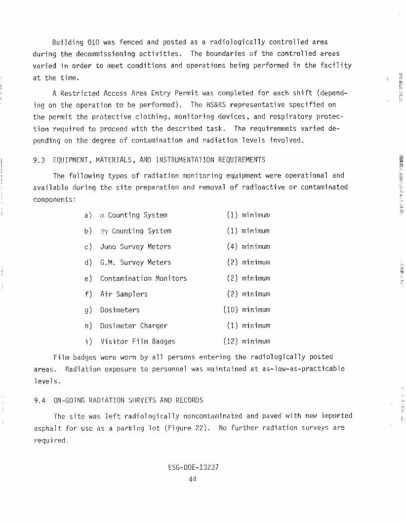
Building 010 was fenced and posted as a radiological ly controlled area
during the decommissioning a c t i v i t i e s . The boundaries of the controlled areas
varied i n order t o meet conditions and operations being performed in the f a c i l i t y
a t the time.
A Restricted Access Area Entry Permit was completed f o r each s h i f t (depend-
ing on the operation t o be performed). The HS&RS representat ive specif ied on
the permit the protect ive c lothing, monitoring devices, and respira tory protec-
t ion required t o proceed with the described t ask . The requirements varied de-
pending on the degree of contamination and radia t ion levels involved.
e 9.3 EQUIPMENT, MATERIALS, AND INSTRUMENTATION REQUIREMENTS
The following types of radiat ion monitoring equipment were operational and
avai lable during the s i t e preparation and removal of radioactive o r contaminated
components:
a ) a Counting System (1) minimum
b) By Counting System (1) m i n i m u m
c ) Juno Survey Meters
d) G.M. Survey Meters
( 4 ) minimum
(2) minimum
e ) Contamination Monitors ( 2 ) minimum
f ) Air Samplers ( 2 ) m i n i m u m
g ) Dosimeters (10) minimum
h ) Dosimeter Charger (1) minimum
i ) Vis i tor Film Badges (12) minimum
Film badges were worn by a l l persons entering the radiological ly posted
areas . Radiation exposure t o personnel was maintained a t as-low-as-practicable
1 eve1 s .
9.4 ON-GOING RADIATION SURVEYS A N D RECORDS
The s i t e was l e f t radiological ly noncontaminated and paved with new imported
asphalt f o r use as a parking l o t (Figure 22). No fu r the r radiat ion surveys a r e
requi red.
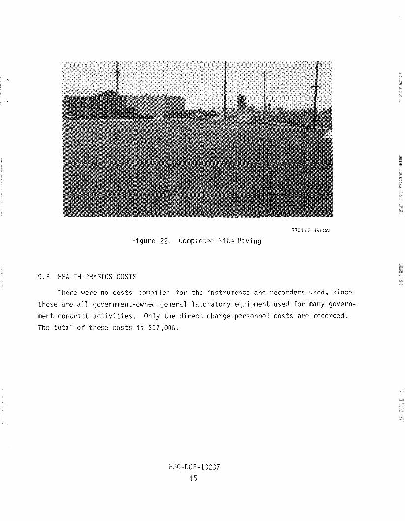
7704-6:?1496CN
Figure 22. Completed Si te Paving
9 .5 HEALTH PHYSICS COSTS
There were no costs compiled for the instruments and recorders used, since
these are a l l government-owned general laboratory equipment used for many govern-
ment contract ac t iv i t i e s . Only the d i rec t charge personnel costs are recorded.
The total o f these costs i s $27,000.

1
10.1 SALVAGEABLE MATERIAL A N D EQUIPMENT
Very l i t t l e of the original s t ruc tu re was salvaged. The principal items
were the e l e c t r i c a l transformers, crane d o l l i e s , and a few e l e c t r i c motors in
the heating and ven t i l a t ion system. Only the crane do l l i e s required decontami-
nation. I t was performed a t the Radioactive Material Disposal Facil i t y ( R M D F ) ,
which i s f u l l y equipped fo r t h i s a c t i v i t y . Estimated salvage value on the
government surplus 1 i s t i s $10,000.
The noncontaminated sampled concrete was used fo r some of the excavation
backfi l l and f o r drainage di tch repa i r in another nearby area.
10.2 FACILITIES AND SITE
No s t ruc tu res remain. The s i t e i s paved over f o r use as a parking l o t .
Since this i s a small area (114 ac re ) in a large leasehold (90 ac r e s ) , there i s
l i t t l e i f any value assigned t o the recovery of the s i t e as land area. The
principal benef i t i s the freedom from fu tu re surveil lance and l icensing require-
men t s .
11.1 ADMINISTRATIVE
The a d m i n i s t r a t i v e hours r e q u i r e d t o manage t h e t ask comprise m o n i t o r i n g
o f c o s t and schedule performance, q u a l i t y assurance, and procurement. The
t o t a l t ime i s recorded as 2100 manhours.
11.2 ENGINEERING AND LABOR
The Engineer ing and Labor a c t i v i t y i nc l udes p repa ra t i on o f p lans and pro-
cedures, decontaminat ion opera t ions , r a d i o a c t i v e waste hand l i ng and packaging,
maintenance suppor t , Hea l t h Physics suppor t , e tc . , f o r t he decommissioning work
and supe rv i s i on o f t h e c o n t r a c t o r s employed t o do t h e work. I t i s recorded as
6400 manhours.
11.3 SPECIAL PURCHASED S E R V I C E S
Purchased l a b o r f rom c o n t r a c t o r s i nc l udes a1 1 o f t h e s k i l l e d and u n s k i l l e d
1 abor. Sk i 11 ed l a b o r i n c l udes machine operators , p i p e f i t t e r s , and r i g g e r s .
U n s k i l l e d l a b o r i nc l udes general l a b o r e r s f o r hand d igg ing and m a t e r i a l s o r t i n g .
The con t r a c t 1 abor p rov ided 3500 manhours .
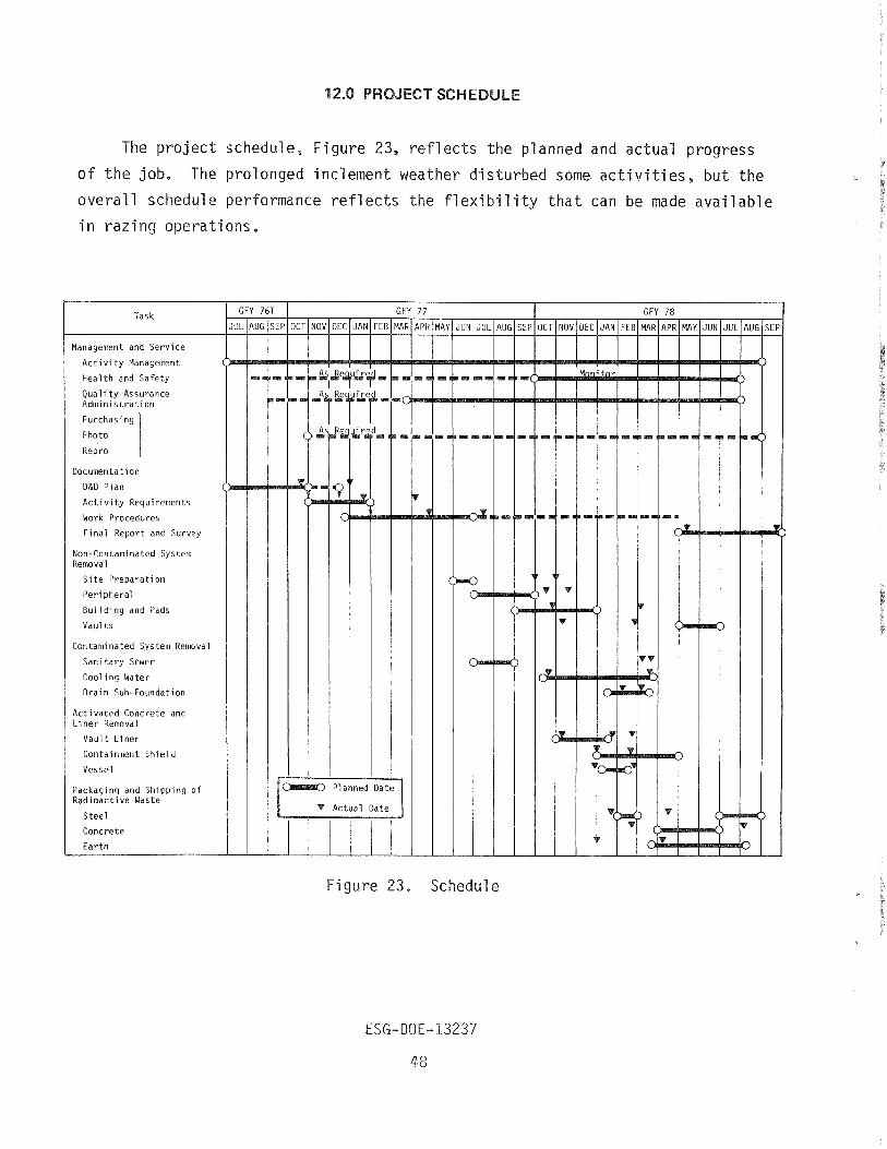
The project schedule, Figure 23, ref lects the planned and actual progress
of the job. The prolonged inclement weather disturbed some ac t iv i t i e s , b u t the
overall schedule performance ref1 ects the f l exi bil i ty that can be made avai 1 able
in razing operations.
Task
Management and Service
Activity Management
Health and Safety
Qua l i t y Assurance Administration
Purchasing
Photo
Repro
D&D Plan
I Documentation
Activity Requirements
Work Procedures
Final Report and Survey
Non-Contaminated System Removal
S i t e Preparation
Peripheral
Building and Pads
Vaults
Contaminated System Removal
Sanitary Sewer
Cooling Water
Drain Sub-Foundation
Activated Concrete and Liner Removal
Vault Liner
Containment Shield
Vessel
Packaging and Shipping of Radioactive Waste
Steel
Concrete
Earth
Figure 23 . Schedule
DECOMMISSIONING COSTS
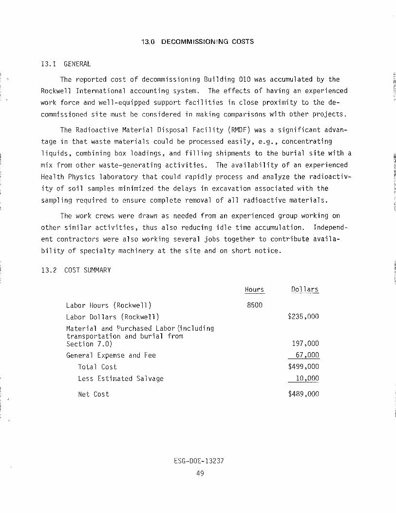
13.1 GENERAL
The reported cost of decommissioning Building 010 was accumulated by the
Rockwell International accounting system. The e f f ec t s of having an experienced
work force and well-equipped support f a c i l i t i e s in close proximity t o the de-
commissioned s i t e must be considered in making comparisons with other projects .
The Radioactive Material Disposal Fac i l i ty ( R M D F ) was a s ign i f i can t advan-
tage in t ha t waste materials could be processed ea s i l y , e .g . , concentrating
l iqu ids , combining box loadings, and f i l l i n g shipments t o the burial s i t e with a
mix from other waste-generating a c t i v i t i e s . The a v a i l a b i l i t y of an experienced
Health Physics laboratory t h a t could rapidly process and analyze the radioactiv-
i t y of so i l samples minimized the delays in excavation associated with the
sampling required t o ensure complete removal of a11 radioactive materials .
The work crews were drawn as needed from an experienced group working on
other s imi lar a c t i v i t i e s , thus a l so reducing i d l e time accumulation. Independ-
en t contractors were a l so working several jobs together t o contribute availa-
b i l i t y of spec ia l ty machinery a t the s i t e and on shor t notice.
13.2 COST SUMMARY
Labor Hours (Rockwell )
Labor Do1 1 a r s (Rockwell )
Material and Purchased Labor (i ncl udi ng t ranspor ta t ion and burial from Section 7.0)
General Expense and Fee
Total Cost
Less Estimated Salvage
Hours Do1 1 a r s
8500
$235,000
Net Cost