Embed Size (px)
Citation preview
Solidworks2009- surface modeling – Mouse
Non-Commercial Use
www.dicksonsham.com
Version 2a- June 2010 Written by Dickson Sham
A- 1
Solidworks 2009 Surface-modeling
(Tutorial 2-Mouse)
Surface-modeling
Solid-modeling
Assembly Design
Design with a Master Model
Solidworks2009- surface modeling – Mouse
Non-Commercial Use
www.dicksonsham.com
Version 2a- June 2010 Written by Dickson Sham
A- 2
Surface-modeling
Tutorial 2A– Import 2D outline drawing into Solidworks2009
– Build 3D curves based on the imported drawing
– Build the upper surfaces of the mouse
Tutorial 2B– Do the draft analysis to search any undercut portion on the
upper surfaces
– Adjust the curvature of the problem surface manually
– Build the lower surfaces of the mouse
– Convert the surfaces into a solid
Tutorial 2C– Build the parting surfaces based on the imported drawing
– Create components from the finished model
– Re-assemble the components into an assembly
– Modify the outlook of the master model and then get all
components updated automatically
Please be reminded that this series of tutorials is designed
to demonstrate a design approach with Solidworks, rather
than the command itself.

Solidworks2009- surface modeling – Mouse
Non-Commercial Use
www.dicksonsham.com
Version 2a- June 2010 Written by Dickson Sham
A- 3
Tutorial 2A• Create a new project folder
• Download mouse_outline.dxf on web
http://myweb.polyu.edu.hk/~mmdsham/Ex2.htm
• Enter Solidworks2009 by double-clicking its icon on the
desktop.
(BEFORE START, reset the layout of workbench if
necessary)
• Select “File/Open” on the menu bar and select the
drawing (mouse_outline.dxf)
• Select “Create new solidworks drawing”
• Select “Next”
• (You should have a preview); select “Next” again
• Select “Finish”
Not For Commercial Use

Solidworks2009- surface modeling – Mouse
Non-Commercial Use
www.dicksonsham.com
Version 2a- June 2010 Written by Dickson Sham
A- 4
Tutorial 2ATo confirm that the size of the drawing is correct:-
• Click “Annotations” icon
• Click “Smart Dimension” icon
• Click on the scale line of the drawing
• Check if the displayed dimension is 50mm; If
not, we need to enlarge or shrink the drawing
into the correct size.
To copy and paste the drawing into 3D space:-
• Multi-select all entities on the drawing, except
the scale bar;
• Select “Edit /Copy” on the top menu
Check if it is 50

Solidworks2009- surface modeling – Mouse
Non-Commercial Use
www.dicksonsham.com
Version 2a- June 2010 Written by Dickson Sham
A- 5
Tutorial 2A
• Select “File/New” on the menu bar;
• Select “Part”
• Click OK
• Select “View/Origins” on the top menu
• (A blue dot appears on the working area, which is the system origin)
• Click “Sketch” icon and select Front Plane
• Click on the origin
• Select “Edit/ Paste” on the top menu bar
• (All 2D elements are now pasted onto this sketch plane, Front Plane)
• Click “Exit Sketch” icon to exit

Solidworks2009- surface modeling – Mouse
Non-Commercial Use
www.dicksonsham.com
Version 2a- June 2010 Written by Dickson Sham
A- 6
Tutorial 2ATo hide the arc centerpoints and control points
of splines (optional):-
• Select “Tools/ Options…” on the top menu
• On the first tab page “System Options”, click
on “Sketch”
• Deselect the two options
– Display arc centerpoints in
part/assembly sketches
– Display entity points in part/assembly
sketches
• Click ok to complete
Hide arc centers
& control points

Solidworks2009- surface modeling – Mouse
Non-Commercial Use
www.dicksonsham.com
Version 2a- June 2010 Written by Dickson Sham
A- 7
Tutorial 2A
To split the drawing into three individual views and
position them:-
• Click tabpage “Features”
• Click “Reference Geometry”, then select “Plane”
• Select Front Plane on the tree
• Enter 150mm as D1
• Click ok to complete
• Create an offset plane, 150mm from Top Plane
• Create an offset plane, 150mm from Right Plane
• Duplicate two more “Sketch1” by copy-and-paste
function
• Drag “Sketch.1” to the position after “plane3” on
tree
• Rename them as “Front View”, “Top View” &
“Right View” (right-click the sketches and select
“Feature Properties”)

Solidworks2009- surface modeling – Mouse
Non-Commercial Use
www.dicksonsham.com
Version 2a- June 2010 Written by Dickson Sham
A- 8
Tutorial 2A
• Right-click on “Front View” on the tree and
select “Edit Sketch Plane”
• Select “Plane.1”
• Click ok to confirm
• Similarly, right-click “Top View” and select
“Edit Sketch Plane”;
• Select “Plane.2”
• Click ok to confirm
• Similarly, right-click “Right View” and select
“Edit Sketch Plane”;
• Select “Plane.3”
• Click ok to confirm
Edit sketch
plane
Solidworks2009- surface modeling – Mouse
Non-Commercial Use
www.dicksonsham.com
Version 2a- June 2010 Written by Dickson Sham
A- 9
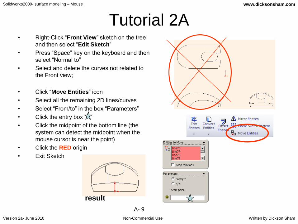
Tutorial 2A• Right-Click “Front View” sketch on the tree
and then select “Edit Sketch”
• Press “Space” key on the keyboard and then
select “Normal to”
• Select and delete the curves not related to
the Front view;
• Click “Move Entities” icon
• Select all the remaining 2D lines/curves
• Select “From/to” in the box “Parameters”
• Click the entry box
• Click the midpoint of the bottom line (the
system can detect the midpoint when the
mouse cursor is near the point)
• Click the RED origin
• Exit Sketch
result
Solidworks2009- surface modeling – Mouse
Non-Commercial Use
www.dicksonsham.com
Version 2a- June 2010 Written by Dickson Sham
A- 10
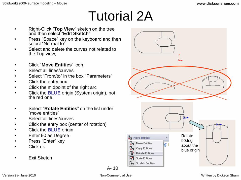
Tutorial 2A• Right-Click “Top View” sketch on the tree
and then select “Edit Sketch”
• Press “Space” key on the keyboard and then select “Normal to”
• Select and delete the curves not related to the Top view;
• Click “Move Entities” icon
• Select all lines/curves
• Select “From/to” in the box “Parameters”
• Click the entry box
• Click the midpoint of the right arc
• Click the BLUE origin (System origin), not the red one.
• Select “Rotate Entities” on the list under “move entities”
• Select all lines/curves
• Click the entry box (center of rotation)
• Click the BLUE origin
• Enter 90 as Degree
• Press “Enter” key
• Click ok
• Exit Sketch
Rotate
90deg
about the
blue origin

Solidworks2009- surface modeling – Mouse
Non-Commercial Use
www.dicksonsham.com
Version 2a- June 2010 Written by Dickson Sham
A- 11
Tutorial 2A• Right-Click “Right View” sketch on the tree
and then select “Edit Sketch”
• Press “Space” key on the keyboard and then select “Normal to”
• Select and delete the curves not related to the Right view;
• Click “Move Entities” icon
• Select all lines/curves
• Select “From/to” in the box “Parameters”
• Click the entry box
• Click the point
• Click the BLUE origin (System origin)
• Click “Move Entities” icon again
• Select all lines/curves
• Select “X/Y” in the box “Parameters”
• Enter -2.85 as X
• Click ok to complete
• Exit Sketch

Solidworks2009- surface modeling – Mouse
Non-Commercial Use
www.dicksonsham.com
Version 2a- June 2010 Written by Dickson Sham
A- 12
Tutorial 2A• (Now we have positioned the three views at
the correct places. These will be a good
reference for us to build the 3D in the middle of
the screen.)
• (We can compare our working 3D with the
reference at any standard viewpoint at any
time.)
To Hide all offset planes:-
• Multi-select Plane1, Plane2 & Plane3 on the
tree
• Right-Click and select “Hide”
Top view
Right view
Front view
Anytime when we press
“space” key on the
keyboard, we can select
a standard viewpoint
Not For Commercial Use
Solidworks2009- surface modeling – Mouse
Non-Commercial Use
www.dicksonsham.com
Version 2a- June 2010 Written by Dickson Sham
A- 13
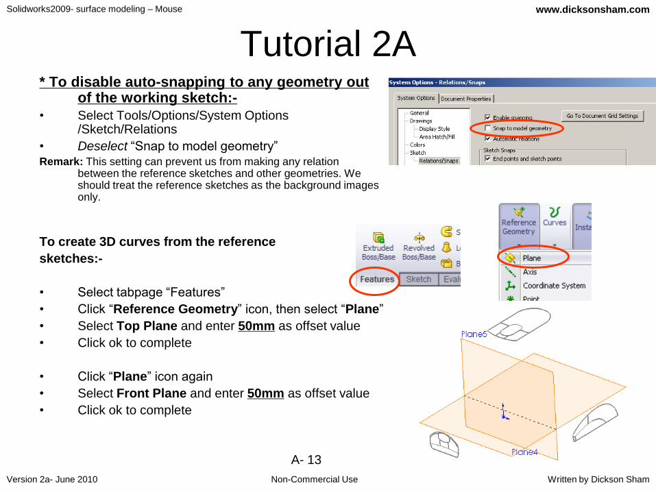
Tutorial 2A* To disable auto-snapping to any geometry out
of the working sketch:-
• Select Tools/Options/System Options /Sketch/Relations
• Deselect “Snap to model geometry”Remark: This setting can prevent us from making any relation
between the reference sketches and other geometries. We should treat the reference sketches as the background images only.
To create 3D curves from the reference
sketches:-
• Select tabpage “Features”
• Click “Reference Geometry” icon, then select “Plane”
• Select Top Plane and enter 50mm as offset value
• Click ok to complete
• Click “Plane” icon again
• Select Front Plane and enter 50mm as offset value
• Click ok to complete

Solidworks2009- surface modeling – Mouse
Non-Commercial Use
www.dicksonsham.com
Version 2a- June 2010 Written by Dickson Sham
A- 14
Tutorial 2A• Click “Sketch” icon and select “Plane4”;
• Press “Space” key on the keyboard and then select “Normal to”
• Draw an Arc (R90mm), with two ends symmetric
about the y-axis and its midpoint at the origin;
• (Remark: a centerline is needed to define the
symmetry of two arc ends)
• (Remark: To define symmetry, multi-select the two arc
ends first and then the centerline)
• (Remark: the arc is a little longer than the reference)
• Exit Sketch
• Click an open area to deselect the Sketch (Sketch4)
• Click “Sketch” icon and select “Plane5”;
• Draw an Arc (R150mm), with two ends symmetric
about the y-axis and the peak 11mm from the x-axis;
• Reminded that the arc should be a little bit longer than
the reference;
• Exit Sketch
origin
symmetric

Solidworks2009- surface modeling – Mouse
Non-Commercial Use
www.dicksonsham.com
Version 2a- June 2010 Written by Dickson Sham
A- 15
Tutorial 2A• Select “Insert / Curve / Projected…” on
the top menu bar
• Select “Sketch4” & “Sketch5”;
• Click ok to complete
• (“Sketch.4” and “Sketch.5” are both hidden
automatically after the projection)
• Hide “Plane4” & “Plane5” The new curve is
the intersection
between the
projections of both
curves
Sketch5
Sketch4
The new curve can fit the
shapes for both top view
and front view

Solidworks2009- surface modeling – Mouse
Non-Commercial Use
www.dicksonsham.com
Version 2a- June 2010 Written by Dickson Sham
A- 16
Tutorial 2A• Click “Reference Geometry” icon, then
select “Plane”
• Select Right Plane and enter 30.5mm as
offset value
• Click ok to complete
• Click “Sketch” icon and select the new
plane “Plane6”
• Draw two arcs as shown
• Reminded that two arcs must be tangent to
each other; one end of the small arc is
touching the x-axis; one end of the bigger
arc is just near y-axis
• (Remark: Do not make any relation with
other sketch)
• Exit Sketch
• Hide “Plane6”
Right Plane
New Plane

Solidworks2009- surface modeling – Mouse
Non-Commercial Use
www.dicksonsham.com
Version 2a- June 2010 Written by Dickson Sham
A- 17
Tutorial 2ATo create surfaces from 3D curves:-
• Click “3D Sketch” icon
• Select “Curve1” (projected curve) on the tree
• Click “Convert” icon
• Exit Sketch (by clicking “3d sketch” or “exit”)
• Click “3D Sketch” icon
• Select “Sketch6” on the tree
• Click “Convert Entities” icon
• Exit Sketch (by clicking “3d sketch” or “exit”)
(This is a limitation of Solidworks2009 that we cannot
create an extruded surface based on a
projected curve; but after converting it into 3D
Sketch, it is possible)
(This is another limitation of Solidworks2009 that we
cannot create an extruded surface along the
direction that is parallel to the sketch plane; but
after converting it into 3D Sketch, it is possible)
Sketch6 should match
the profile in Right
View
Curve1 Sketch6
Exit
sketch
Solidworks2009- surface modeling – Mouse
Non-Commercial Use
www.dicksonsham.com
Version 2a- June 2010 Written by Dickson Sham
A- 18
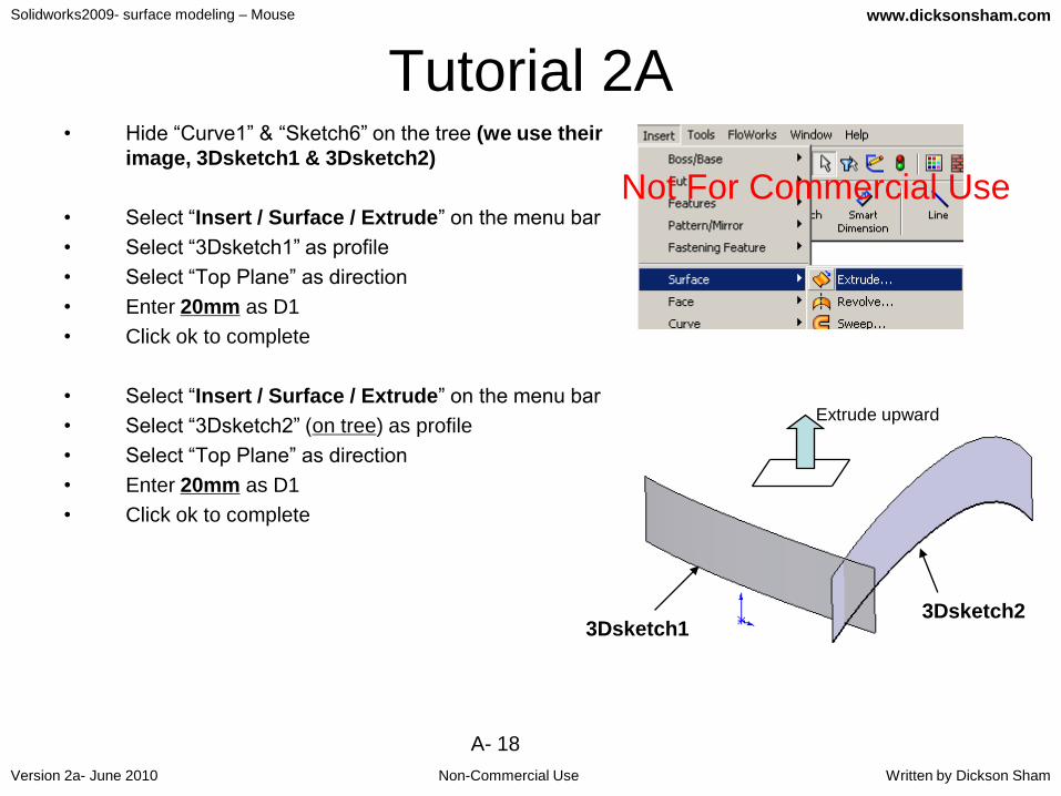
Tutorial 2A• Hide “Curve1” & “Sketch6” on the tree (we use their
image, 3Dsketch1 & 3Dsketch2)
• Select “Insert / Surface / Extrude” on the menu bar
• Select “3Dsketch1” as profile
• Select “Top Plane” as direction
• Enter 20mm as D1
• Click ok to complete
• Select “Insert / Surface / Extrude” on the menu bar
• Select “3Dsketch2” (on tree) as profile
• Select “Top Plane” as direction
• Enter 20mm as D1
• Click ok to complete
3Dsketch13Dsketch2
Extrude upward
Not For Commercial Use

Solidworks2009- surface modeling – Mouse
Non-Commercial Use
www.dicksonsham.com
Version 2a- June 2010 Written by Dickson Sham
A- 19
Tutorial 2ATo add a draft onto extruded surfaces:-
• Select tabpage “Features”, then click “Draft”
• Select “Parting Line” as Type of Draft
• Select “Top Plane” as Direction of Pull
• Click “Reverse Direction” icon
• Select the bottom edge of “Surface-Extrude1”
as the parting line
• Enter 5deg as Draft Angle
• Click ok to complete
• Click “Draft” again
• Select “Parting Line” as Type of Draft
• Select “Top Plane” as Direction of Pull
• Select the TWO bottom edges of “Surface-
Extrude2” as parting lines
• Enter 5deg as Draft Angle
• Click ok to complete
Draft Inward
Parting
linesParting
line

Solidworks2009- surface modeling – Mouse
Non-Commercial Use
www.dicksonsham.com
Version 2a- June 2010 Written by Dickson Sham
A- 20
Tutorial 2ATo duplicate a surface by mirroring:-
• Click “Mirror” icon
• Select “Right Plane” as Mirror Plane
• Click on “Bodies to Mirror”
• Select the surface “Draft2”
• Click ok to complete
To add a fillet between two surfaces:-
• Click “Fillet” icon
• Select “Face Fillet” as Type
• Enter 5mm as Radius
• Select the face
• Click “Reverse Face Normal”
• Click the entry box “Face Set 2” (pink color)
• Select the face
• Click ok to complete
Both Face Normals
pointing inward

Solidworks2009- surface modeling – Mouse
Non-Commercial Use
www.dicksonsham.com
Version 2a- June 2010 Written by Dickson Sham
A- 21
Tutorial 2ATo add another face fillet :-
• Click “Fillet” icon again
• Select “Face Fillet” as Type
• Enter 5mm as Radius
• Select the face
• Click “Reverse Face Normal”
• Click the entry box “Face Set 2” (pink color)
• Select the face
• Click ok to complete
To hide the surface:-
• Right- Click on any face of the surface
• Select “Hide”
Solidworks2009- surface modeling – Mouse
Non-Commercial Use
www.dicksonsham.com
Version 2a- June 2010 Written by Dickson Sham
A- 22
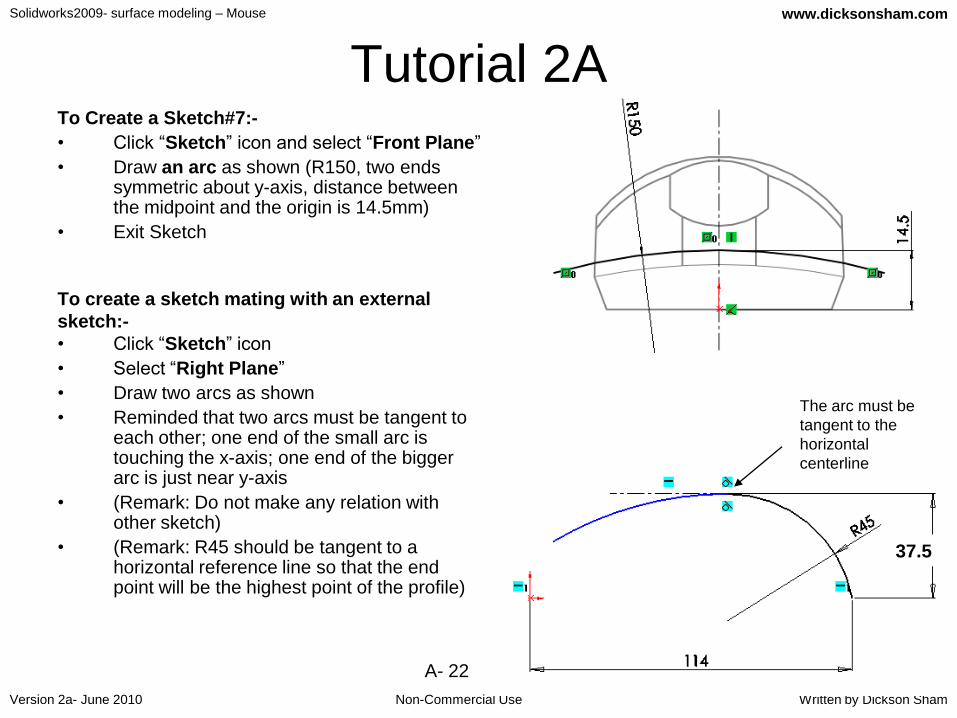
Tutorial 2ATo Create a Sketch#7:-
• Click “Sketch” icon and select “Front Plane”
• Draw an arc as shown (R150, two ends symmetric about y-axis, distance between the midpoint and the origin is 14.5mm)
• Exit Sketch
To create a sketch mating with an external
sketch:-
• Click “Sketch” icon
• Select “Right Plane”
• Draw two arcs as shown
• Reminded that two arcs must be tangent to each other; one end of the small arc is touching the x-axis; one end of the bigger arc is just near y-axis
• (Remark: Do not make any relation with other sketch)
• (Remark: R45 should be tangent to a horizontal reference line so that the end point will be the highest point of the profile)
The arc must be
tangent to the
horizontal
centerline
37.5
Solidworks2009- surface modeling – Mouse
Non-Commercial Use
www.dicksonsham.com
Version 2a- June 2010 Written by Dickson Sham
A- 23
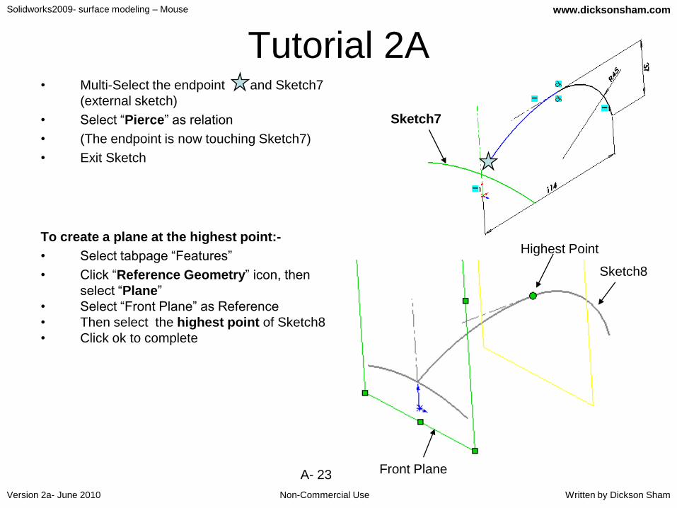
Tutorial 2A• Multi-Select the endpoint and Sketch7
(external sketch)
• Select “Pierce” as relation
• (The endpoint is now touching Sketch7)
• Exit Sketch
To create a plane at the highest point:-
• Select tabpage “Features”
• Click “Reference Geometry” icon, then
select “Plane”
• Select “Front Plane” as Reference
• Then select the highest point of Sketch8
• Click ok to complete
Sketch7
Highest Point
Front Plane
Sketch8

Solidworks2009- surface modeling – Mouse
Non-Commercial Use
www.dicksonsham.com
Version 2a- June 2010 Written by Dickson Sham
A- 24
Tutorial 2A
To create a sketch on the new plane:-
(Sketch#9)
• Click “Sketch” icon;
• Select the new plane “Plane7”;
• Draw an arc as shown; add a symmetry
constraint onto the endpoints;
• Then add a coincident relation between
the arc and the highest point of Sketch8
• Add a dimension R38mm onto the arc
• Remark: the endpoints should be a little
bit out of the background image
• Exit Sketch
Add a coincident
relation between the
arc and the highest
point of Sketch8
symmetry

Solidworks2009- surface modeling – Mouse
Non-Commercial Use
www.dicksonsham.com
Version 2a- June 2010 Written by Dickson Sham
A- 25
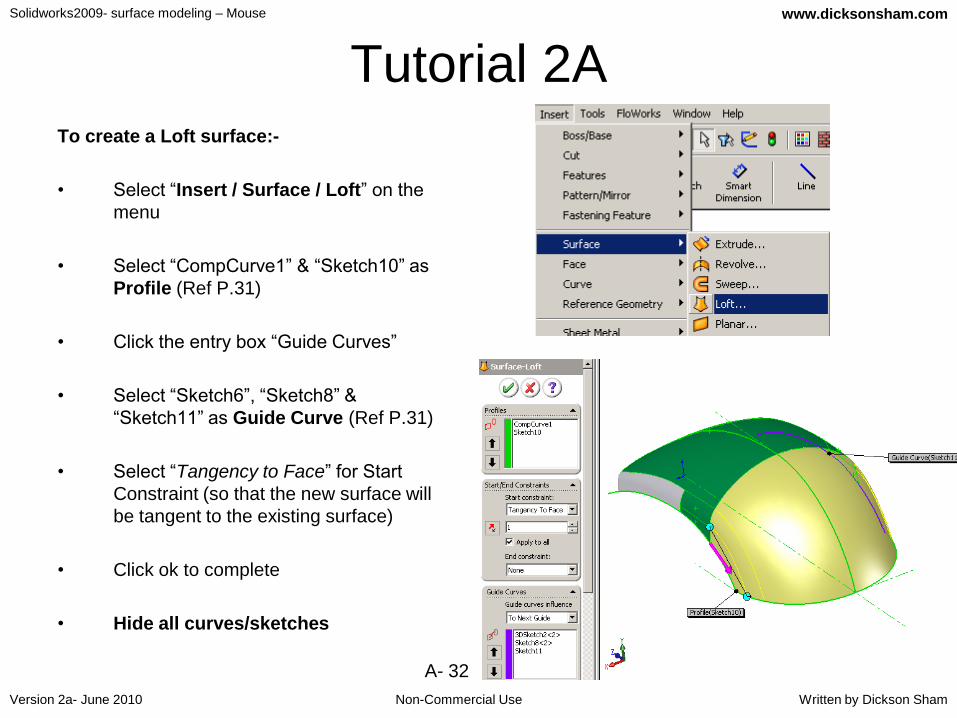
Tutorial 2ATo create a Loft Surface:-
• Select “Insert / Surface / Loft” on
the top menu
• Select “Sketch7” & “Sketch9” as
Profile
• Click the entry box “Guide Curves”
• Select “Sketch8” as Guide Curve
• Click ok to complete
(“Sketch7”, “Sketch8”, & “Sketch9”
are hidden automatically. If not,
hide them manually.)
Hide “Plane7” too Sketch7
Sketch8
Sketch9

Solidworks2009- surface modeling – Mouse
Non-Commercial Use
www.dicksonsham.com
Version 2a- June 2010 Written by Dickson Sham
A- 26
Tutorial 2ATo Trim surfaces and form a joined
surface:-
• Show “Fillet2” on the tree
• Select “Insert / Surface / Trim” on
the top menu bar
• Select “Mutual” as Trim Type
• Select surfaces “Fillet2” & „Surface-
Loft1”
• Select “Keep Selections”
• Select “Split all”
• Click the entry box (Pieces to keep)
• Select the two faces
• Click ok to complete
Fillet2
Surface-Loft1
Solidworks2009- surface modeling – Mouse
Non-Commercial Use
www.dicksonsham.com
Version 2a- June 2010 Written by Dickson Sham
A- 27
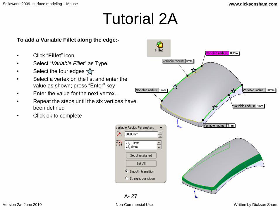
Tutorial 2ATo add a Variable Fillet along the edge:-
• Click “Fillet” icon
• Select “Variable Fillet” as Type
• Select the four edges
• Select a vertex on the list and enter the
value as shown; press “Enter” key
• Enter the value for the next vertex…
• Repeat the steps until the six vertices have
been defined
• Click ok to complete
Solidworks2009- surface modeling – Mouse
Non-Commercial Use
www.dicksonsham.com
Version 2a- June 2010 Written by Dickson Sham
A- 28
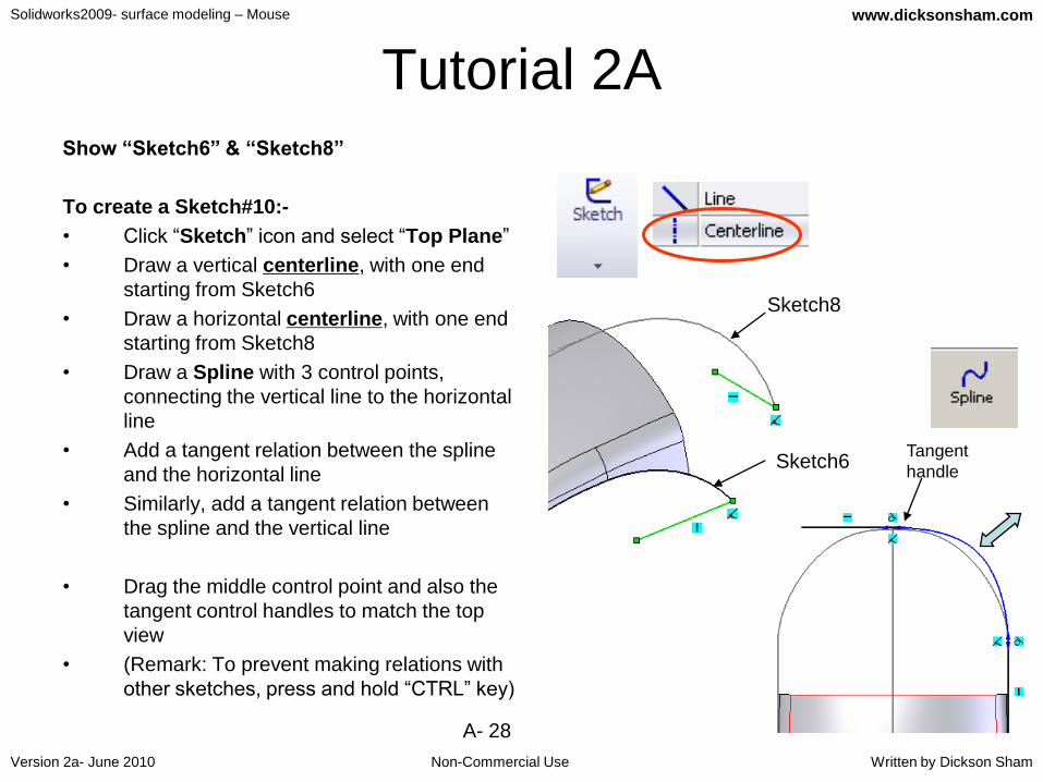
Tutorial 2AShow “Sketch6” & “Sketch8”
To create a Sketch#10:-
• Click “Sketch” icon and select “Top Plane”
• Draw a vertical centerline, with one end
starting from Sketch6
• Draw a horizontal centerline, with one end
starting from Sketch8
• Draw a Spline with 3 control points,
connecting the vertical line to the horizontal
line
• Add a tangent relation between the spline
and the horizontal line
• Similarly, add a tangent relation between
the spline and the vertical line
• Drag the middle control point and also the
tangent control handles to match the top
view
• (Remark: To prevent making relations with
other sketches, press and hold “CTRL” key)
Sketch8
Sketch6Tangent
handle

Solidworks2009- surface modeling – Mouse
Non-Commercial Use
www.dicksonsham.com
Version 2a- June 2010 Written by Dickson Sham
A- 29
Tutorial 2A• Draw another Vertical centerline, starting
from the origin
• Click “Mirror Entities” icon
• Select the Spline as “entities to mirror”
• Select the centerline as “mirror about”
• Click ok
• Exit Sketch
Draw a centerline
Result
Result

Solidworks2009- surface modeling – Mouse
Non-Commercial Use
www.dicksonsham.com
Version 2a- June 2010 Written by Dickson Sham
A- 30
Tutorial 2ATo duplicate Sketch6 about a mirror plane:-
• Click “Reference Geometry” icon, then select
“Plane”
• Select Right Plane on the tree
• Enter 30.5mm as D1
• Select “Reverse Direction”
• Click ok to complete
• Click “Sketch” icon and select the new Plane
• Multi-select all arcs of Sketch6
• Click “Convert Entities” icon
• Exit Sketch
• Hide “Plane8”
(This is a limitation of Solidworks2009 that
sketches, 3d sketches or 3d curves cannot be
mirrored in the 3D environment) Sketch6
Sketch
plane,
(Plane8)
Two arcs are
projected from
Sketch6 to this
sketch plane
Not For Commercial Use

Solidworks2009- surface modeling – Mouse
Non-Commercial Use
www.dicksonsham.com
Version 2a- June 2010 Written by Dickson Sham
A- 31
Tutorial 2ATo obtain a boundary of a surface (Loft1):-
• Select “insert / Curve / Composite” on the
menu bar
• Multi-select the five edges of the Loft
• Click ok to complete
CompCurve1
Sketch10Sketch6
Sketch11
Sketch8
Solidworks2009- surface modeling – Mouse
Non-Commercial Use
www.dicksonsham.com
Version 2a- June 2010 Written by Dickson Sham
A- 32
Tutorial 2ATo create a Loft surface:-
• Select “Insert / Surface / Loft” on the
menu
• Select “CompCurve1” & “Sketch10” as
Profile (Ref P.31)
• Click the entry box “Guide Curves”
• Select “Sketch6”, “Sketch8” &
“Sketch11” as Guide Curve (Ref P.31)
• Select “Tangency to Face” for Start
Constraint (so that the new surface will
be tangent to the existing surface)
• Click ok to complete
• Hide all curves/sketches

Solidworks2009- surface modeling – Mouse
Non-Commercial Use
www.dicksonsham.com
Version 2a- June 2010 Written by Dickson Sham
A- 33
Tutorial 2A
To improve the smoothness of a Loft Surface:-
One of the common strategies is to increase the
distance between two sections so that there is more
room to transform one section into the other one,
thus decreasing the shrink marks on the resultant
surface.
We are going to increase the
distance between two sections
The resultant surface has an
obvious shrink mark, which needs
further improvement
Solidworks2009- surface modeling – Mouse
Non-Commercial Use
www.dicksonsham.com
Version 2a- June 2010 Written by Dickson Sham
A- 34
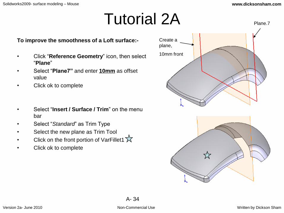
Tutorial 2ATo improve the smoothness of a Loft surface:-
• Click “Reference Geometry” icon, then select
“Plane”
• Select “Plane7” and enter 10mm as offset
value
• Click ok to complete
• Select “Insert / Surface / Trim” on the menu
bar
• Select “Standard” as Trim Type
• Select the new plane as Trim Tool
• Click on the front portion of VarFillet1
• Click ok to complete
Plane.7
Create a
plane,
10mm front
Solidworks2009- surface modeling – Mouse
Non-Commercial Use
www.dicksonsham.com
Version 2a- June 2010 Written by Dickson Sham
A- 35
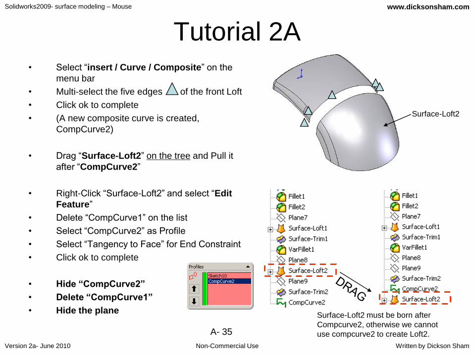
Tutorial 2A• Select “insert / Curve / Composite” on the
menu bar
• Multi-select the five edges of the front Loft
• Click ok to complete
• (A new composite curve is created,
CompCurve2)
• Drag “Surface-Loft2” on the tree and Pull it
after “CompCurve2”
• Right-Click “Surface-Loft2” and select “Edit
Feature”
• Delete “CompCurve1” on the list
• Select “CompCurve2” as Profile
• Select “Tangency to Face” for End Constraint
• Click ok to complete
• Hide “CompCurve2”
• Delete “CompCurve1”
• Hide the plane
Surface-Loft2
Surface-Loft2 must be born after
Compcurve2, otherwise we cannot
use compcurve2 to create Loft2.
Solidworks2009- surface modeling – Mouse
Non-Commercial Use
www.dicksonsham.com
Version 2a- June 2010 Written by Dickson Sham
A- 36
Tutorial 2A
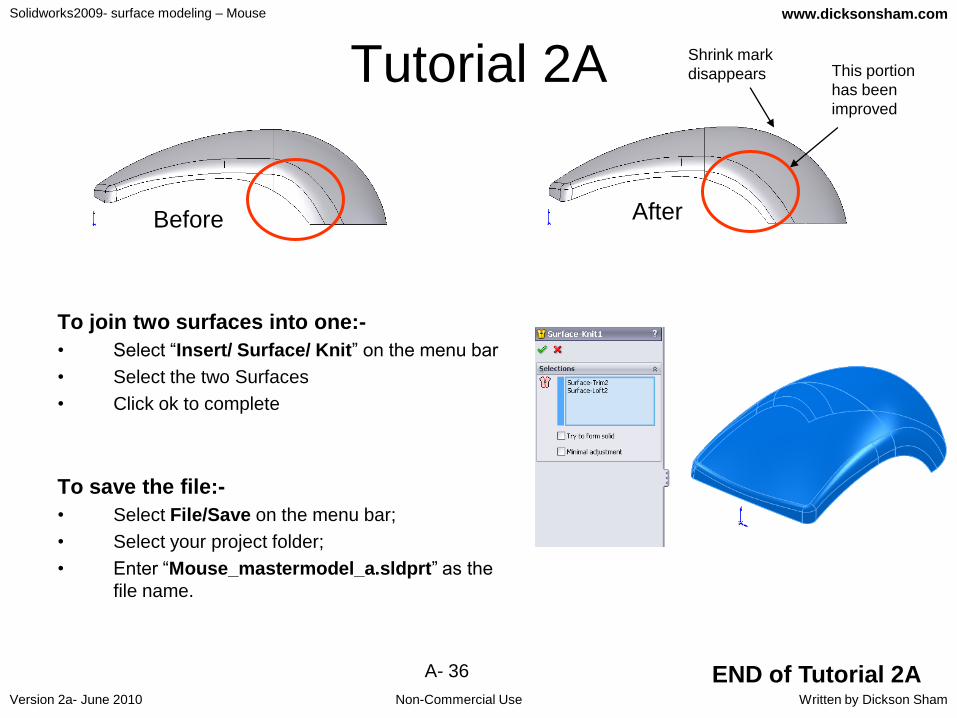
To join two surfaces into one:-
• Select “Insert/ Surface/ Knit” on the menu bar
• Select the two Surfaces
• Click ok to complete
To save the file:-
• Select File/Save on the menu bar;
• Select your project folder;
• Enter “Mouse_mastermodel_a.sldprt” as the
file name.
END of Tutorial 2A
Before After
This portion
has been
improved
Shrink mark
disappears

Solidworks2009- surface modeling – Mouse
Non-Commercial Use
www.dicksonsham.com
Version 2a- June 2010 Written by Dickson Sham
A- 37
Tutorial 2BWe continue to build the skin of the upper part. After that, we
need to check if the whole skin can meet the required
shape and has no undercut portion…
• Reopen the file “Mouse_mastermodel_a.sldprt”
• Press “Space” key to activate the orientation selection
• Click “Front View” icon to check the front view
• Click “Top View” icon to check the top view
• Click “Right View” icon to check the right view
(Remark: the surface should match the three reference views)
(Remark: In the real case, the dimensions & locations of all
control curves of the surfaces should be referred to these
imported reference views)
Not For Commercial Use

Solidworks2009- surface modeling – Mouse
Non-Commercial Use
www.dicksonsham.com
Version 2a- June 2010 Written by Dickson Sham
A- 38
Tutorial 2BTo make a sketch:-
• Click “Sketch” icon
• Select “Plane4”
• Multi-select the four curves on the sketch “Top
View”
• Click “Convert Entities” icon
• (We have 4 projected curves from “Top View”)
• Exit Sketch
To remove surface by the projection of a curve:-
• Select “Insert/ Surface / Trim” on the menu bar
• Select “Sketch12” as Trim Tool
• Select “Keep Selections” and then click on the
surface “Surface-Knit1”
• Click ok to complete
• (“Sketch12” is hidden automatically)
Sketch “Top View”
Click HERE
sketch12
Solidworks2009- surface modeling – Mouse
Non-Commercial Use
www.dicksonsham.com
Version 2a- June 2010 Written by Dickson Sham
A- 39
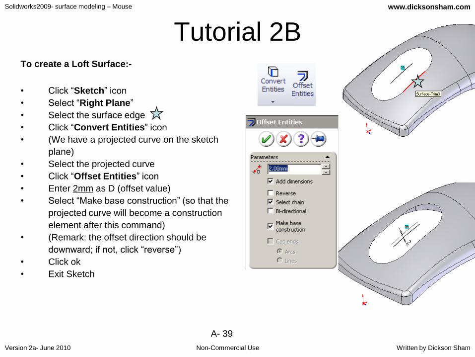
Tutorial 2BTo create a Loft Surface:-
• Click “Sketch” icon
• Select “Right Plane”
• Select the surface edge
• Click “Convert Entities” icon
• (We have a projected curve on the sketch
plane)
• Select the projected curve
• Click “Offset Entities” icon
• Enter 2mm as D (offset value)
• Select “Make base construction” (so that the
projected curve will become a construction
element after this command)
• (Remark: the offset direction should be
downward; if not, click “reverse”)
• Click ok
• Exit Sketch

Solidworks2009- surface modeling – Mouse
Non-Commercial Use
www.dicksonsham.com
Version 2a- June 2010 Written by Dickson Sham
A- 40
Tutorial 2B• Select “Insert / Surface / Loft” on the top menu bar
• Select the Surface Edge1
• Select “Sketch13”
• Select the Surface Edge3
• Click ok to complete
1
23

Solidworks2009- surface modeling – Mouse
Non-Commercial Use
www.dicksonsham.com
Version 2a- June 2010 Written by Dickson Sham
A- 41
Tutorial 2BTo create a Fill Surface:-
• Select “Insert / Surface/ Fill” on the
menu bar
• Select the edge
• Select “tangent” as curvature control
• Select the edge
• Select “contact” as curvature control
• Click ok to complete
To create another Fill surface:-
• Select “Insert / Surface/ Fill” on the
menu bar
• Select the edge
• Select “tangent” as curvature control
• Select the edge
• Select “contact” as curvature control
• Click ok to complete

Solidworks2009- surface modeling – Mouse
Non-Commercial Use
www.dicksonsham.com
Version 2a- June 2010 Written by Dickson Sham
A- 42
Tutorial 2BTo join surfaces as one:-
• Select “Insert/ Surface/ Knit” on the menu
bar
• Select all surfaces
• Click ok to complete
Trim3
Fill1
Loft3
Fill2

Solidworks2009- surface modeling – Mouse
Non-Commercial Use
www.dicksonsham.com
Version 2a- June 2010 Written by Dickson Sham
A- 43
Tutorial 2BTo do the draft analysis on the surface:-
• Select “View/Display/Draft Analysis” on the top menu bar
• Select “Top Plane” on Direction of Pull
• Enter 1deg as A (Angle)
• If the big surface has no undercut, it should either all Green
or all Red.
Green, draft > +1deg
Yellow, -1<draft<+1 deg
Red, draft < -1 deg
(Remark: the top faces are Green but the bottom faces are
Red; that means they must be molded out in opposite
directions)Red (bottom faces)
Green (top faces)
Mold out
directionTop Plane

Solidworks2009- surface modeling – Mouse
Non-Commercial Use
www.dicksonsham.com
Version 2a- June 2010 Written by Dickson Sham
A- 44
Tutorial 2BIf the big surface has no undercut, it should
either all Red or all Green.
• We find a portion with Zero Draft (Yellow) along
the parting line.
• (Yellow portion requires to add more draft)
• Click OK to exit
To modify the curvature of the problem surface:-
• Right-Click “Sketch10” on the tree
• Select “Edit Sketch”
• Draw a new centerline (10deg from the existing
vertical centerline) as shown
• Delete the tangent relation (between the spline
and the vertical centerline)
• Add another tangent relation between the spline and
the new centerline
• Exit Sketch
(All surfaces will be updated automatically)Draw a new centerline
Old
centerline
Solidworks2009- surface modeling – Mouse
Non-Commercial Use
www.dicksonsham.com
Version 2a- June 2010 Written by Dickson Sham
A- 45
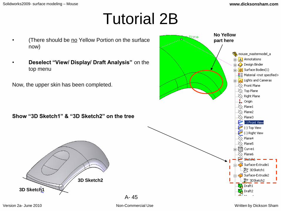
Tutorial 2B• (There should be no Yellow Portion on the surface
now)
• Deselect “View/ Display/ Draft Analysis” on the
top menu
Now, the upper skin has been completed.
Show “3D Sketch1” & “3D Sketch2” on the tree
No Yellow
part here
3D Sketch2
3D Sketch1
Solidworks2009- surface modeling – Mouse
Non-Commercial Use
www.dicksonsham.com
Version 2a- June 2010 Written by Dickson Sham
A- 46
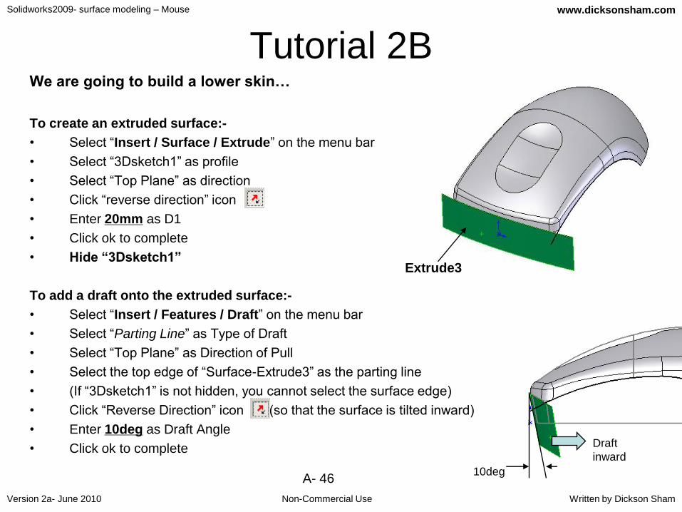
Tutorial 2BWe are going to build a lower skin…
To create an extruded surface:-
• Select “Insert / Surface / Extrude” on the menu bar
• Select “3Dsketch1” as profile
• Select “Top Plane” as direction
• Click “reverse direction” icon
• Enter 20mm as D1
• Click ok to complete
• Hide “3Dsketch1”
To add a draft onto the extruded surface:-
• Select “Insert / Features / Draft” on the menu bar
• Select “Parting Line” as Type of Draft
• Select “Top Plane” as Direction of Pull
• Select the top edge of “Surface-Extrude3” as the parting line
• (If “3Dsketch1” is not hidden, you cannot select the surface edge)
• Click “Reverse Direction” icon (so that the surface is tilted inward)
• Enter 10deg as Draft Angle
• Click ok to complete
Extrude3
Draft
inward
10deg

Solidworks2009- surface modeling – Mouse
Non-Commercial Use
www.dicksonsham.com
Version 2a- June 2010 Written by Dickson Sham
A- 47
Tutorial 2BTo ENable auto-snapping to any geometry out of
the working sketch:-
• Select Tools/Options/System Options /Sketch/Relations
• Select “Snap to model geometry”
To draw 3D curves in 3D environment:-
• Click “3D Sketch” icon
• Click “Centerline” icon
• Select the endpoint of “3DSketch2” as the start point
• (a red local coordinate system appears at this point)
• To define the second point, move the mouse cursor near
the y-axis until it is snapped onto the axis
• Click at the location where is around 20mm below the
local origin
• (a vertical centerline is created)
• Click “Line” icon
• Select the endpoint of “3DSketch2” as the start point
• Press “Space” key on the keyboard
• Select “Front” to switch the front view
• Draw an inclined line (~30mm Length)
• Add an angle dimension 10deg
• Exit Sketch
A local
coordinate
system
Solidworks2009- surface modeling – Mouse
Non-Commercial Use
www.dicksonsham.com
Version 2a- June 2010 Written by Dickson Sham
A- 48
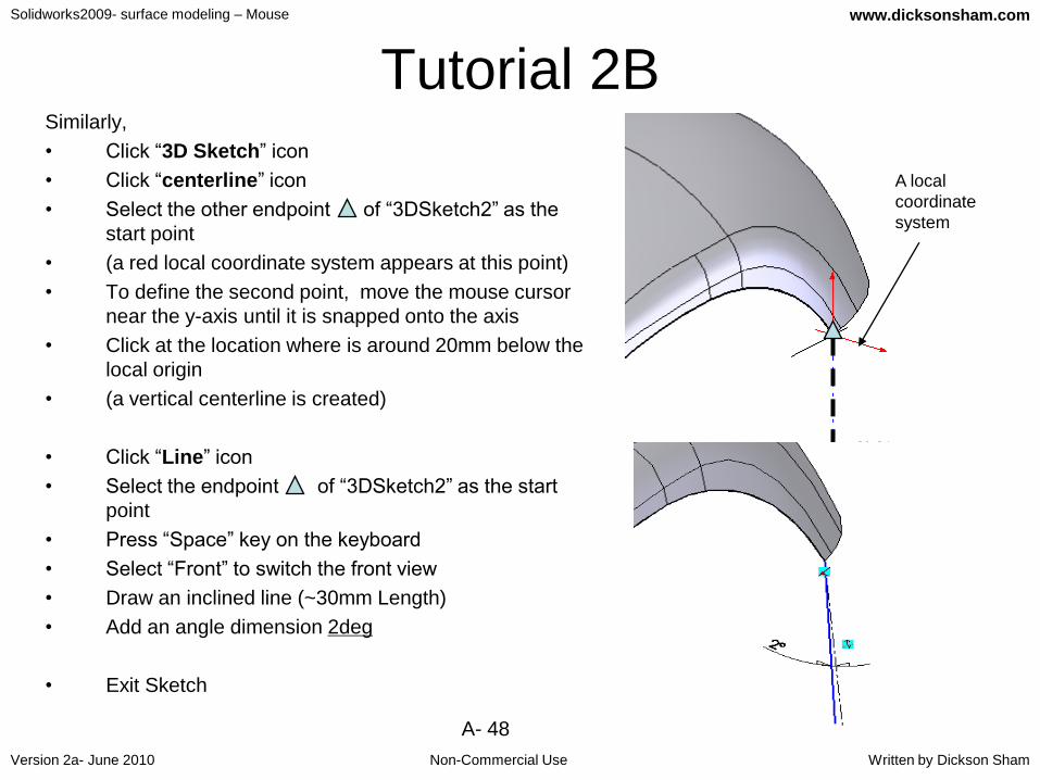
Tutorial 2BSimilarly,
• Click “3D Sketch” icon
• Click “centerline” icon
• Select the other endpoint of “3DSketch2” as the
start point
• (a red local coordinate system appears at this point)
• To define the second point, move the mouse cursor
near the y-axis until it is snapped onto the axis
• Click at the location where is around 20mm below the
local origin
• (a vertical centerline is created)
• Click “Line” icon
• Select the endpoint of “3DSketch2” as the start
point
• Press “Space” key on the keyboard
• Select “Front” to switch the front view
• Draw an inclined line (~30mm Length)
• Add an angle dimension 2deg
• Exit Sketch
A local
coordinate
system

Solidworks2009- surface modeling – Mouse
Non-Commercial Use
www.dicksonsham.com
Version 2a- June 2010 Written by Dickson Sham
A- 49
Tutorial 2BTo Create a Loft Surface:-
• Select “Insert / Surface / Loft” on the menu bar
• Select “3Dsketch3” & “3Dsketch4” as Profile
• Select “3Dsketch2” as guide curve
• Click ok to complete
• Hide all “3d Sketch”
3D
sketch3
3D
sketch4
3D sketch2

Solidworks2009- surface modeling – Mouse
Non-Commercial Use
www.dicksonsham.com
Version 2a- June 2010 Written by Dickson Sham
A- 50
Tutorial 2BTo duplicate a surface by mirroring:-
• Click “Mirror” icon
• Select “Right Plane” as Mirror Plane
• Click on “Bodies to Mirror”
• Select the surface “Loft4”
• Click ok to complete
To add a fillet between two surfaces:-
• Click “Fillet” icon
• Select “Face Fillet” as Type
• Enter 4.5mm as Radius
• Select the face
• Click the entry box “Face Set 2” (pink color)
• Select the face
• Click ok
Both Face Normals
pointing inward
Solidworks2009- surface modeling – Mouse
Non-Commercial Use
www.dicksonsham.com
Version 2a- June 2010 Written by Dickson Sham
A- 51
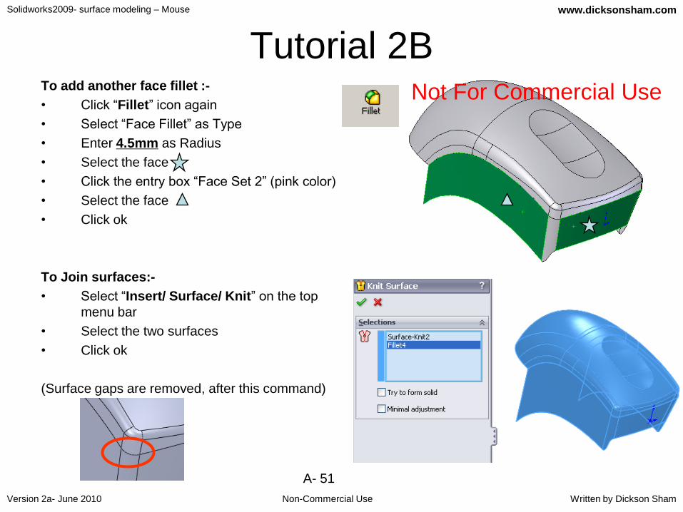
Tutorial 2BTo add another face fillet :-
• Click “Fillet” icon again
• Select “Face Fillet” as Type
• Enter 4.5mm as Radius
• Select the face
• Click the entry box “Face Set 2” (pink color)
• Select the face
• Click ok
To Join surfaces:-
• Select “Insert/ Surface/ Knit” on the top
menu bar
• Select the two surfaces
• Click ok
(Surface gaps are removed, after this command)
Not For Commercial Use

Solidworks2009- surface modeling – Mouse
Non-Commercial Use
www.dicksonsham.com
Version 2a- June 2010 Written by Dickson Sham
A- 52
Tutorial 2BTo create a bottom surface:-
• Click “Sketch” icon
• Select “Front Plane”
• Draw a straight line on x-axis, which is
long enough to go across the whole
model
• (no need to add a symmetric relation)
• Exit Sketch
• Select “Insert / Surface / Extrude” on the
menu bar
• Select the sketch as profile
• (Direction of extrusion is the normal of the
sketch plane, by default)
• Click “Reverse Direction” icon
• Enter 120mm as D1
• Click ok
Draw a line on
x-axis

Solidworks2009- surface modeling – Mouse
Non-Commercial Use
www.dicksonsham.com
Version 2a- June 2010 Written by Dickson Sham
A- 53
Tutorial 2BTo Trim & Join surfaces:-
• Select “Insert/ Surface/ Trim” on the top
menu bar
• Select “Mutual” as Trim Type
• Select the two surfaces
• Click on the entry box “Pieces to keep”
• Click on these two pieces
• Click ok
• (Two surfaces become one. No blue
edges (open edges) cannot be seen; in
other words, it is a CLOSED volume
without any opening)
result

Solidworks2009- surface modeling – Mouse
Non-Commercial Use
www.dicksonsham.com
Version 2a- June 2010 Written by Dickson Sham
A- 54
Tutorial 2BTo form a Solid:-
• Select “Insert/ Boss Bass/ Thicken” on
the top menu bar
• Select the surface
• Select “Create solid from enclosed
volume”
• Click ok
File/Save Mouse_mastermodel_a.sldprt
END of Tutorial 2B
A solid is created;
the surface is
removed from the
tree
1 Surface existed;
no solid bodies on
the tree
BeforeAfter

Solidworks2009- surface modeling – Mouse
Non-Commercial Use
www.dicksonsham.com
Version 2a- June 2010 Written by Dickson Sham
A- 55
Tutorial 2CWe’ve built the upper skin & the lower skin of the mouse. Now,
we are going to create parting surfaces, and then split the
solid into separate components.
• (Reopen the file “Mouse_mastermodel_a.sldprt”) ;
• Press “Space” key to activate the orientation selection
• Click “Front View” icon to check the front view;
• Click “Top View” icon to check the top view;
• Click “Right View” icon to check the right view;
(Remark: the solid should match the three reference views)
Solidworks2009- surface modeling – Mouse
Non-Commercial Use
www.dicksonsham.com
Version 2a- June 2010 Written by Dickson Sham
A- 56
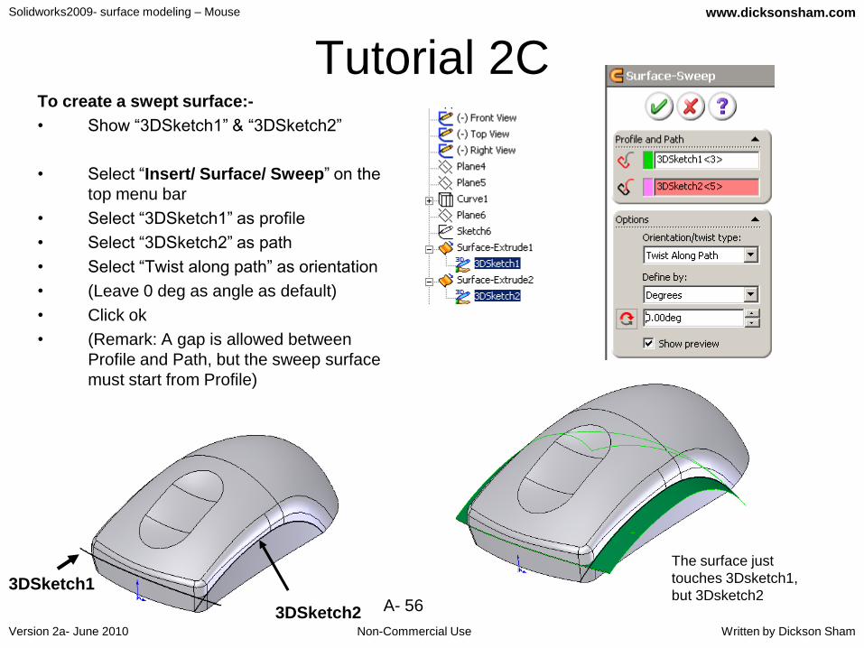
Tutorial 2CTo create a swept surface:-
• Show “3DSketch1” & “3DSketch2”
• Select “Insert/ Surface/ Sweep” on the
top menu bar
• Select “3DSketch1” as profile
• Select “3DSketch2” as path
• Select “Twist along path” as orientation
• (Leave 0 deg as angle as default)
• Click ok
• (Remark: A gap is allowed between
Profile and Path, but the sweep surface
must start from Profile)
3DSketch2
3DSketch1
The surface just
touches 3Dsketch1,
but 3Dsketch2

Solidworks2009- surface modeling – Mouse
Non-Commercial Use
www.dicksonsham.com
Version 2a- June 2010 Written by Dickson Sham
A- 57
Tutorial 2CTo extract a curve from the surface:-
• Click “ 3D Sketch” icon
• Multi-select all tangent edges (5 edges)
• Click “Convert Entities” icon
• Exit Sketch
• (Remark: In Solidworks2009, an extrude surface can only be built from a sketch. Therefore, we need to use “3D sketch” to extract surface edges, instead of using “Insert/Curve/Composite”)
To create an extruded surface:-
• Select “Insert/ Surface/ Extrude” on the top menu bar
• Select the new 3DSketch (“3DSketch5”)
• Select “Top Plane” as Direction
• Enter 3.0mm as D1
• Activate Direction2
• Enter 10.0mm as D2
• Click ok
Exit sketch

Solidworks2009- surface modeling – Mouse
Non-Commercial Use
www.dicksonsham.com
Version 2a- June 2010 Written by Dickson Sham
A- 58
Tutorial 2C
To create an Offset surface:-
• Select “Insert/ Surface/ Offset” on the
menu bar
• Select “Surface-Extrude5” (Click it on the
tree to select all faces)
• Enter 2.5mm as Offset value
• Click “ Reverse Direction” to make the
offset inward
• Click ok
Hide “Surface-Extrude5”
Hide “3DSketch1” & “3DSketch2”
Hide the solid body
Offset inward
“Surface-extrude5”
Result
Solidworks2009- surface modeling – Mouse
Non-Commercial Use
www.dicksonsham.com
Version 2a- June 2010 Written by Dickson Sham
A- 59
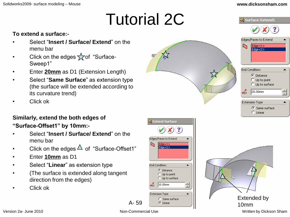
Tutorial 2CTo extend a surface:-
• Select “Insert / Surface/ Extend” on the
menu bar
• Click on the edges of “Surface-
Sweep1”
• Enter 20mm as D1 (Extension Length)
• Select “Same Surface” as extension type
(the surface will be extended according to
its curvature trend)
• Click ok
Similarly, extend the both edges of
“Surface-Offset1” by 10mm:-
• Select “Insert / Surface/ Extend” on the
menu bar
• Click on the edges of “Surface-Offset1”
• Enter 10mm as D1
• Select “Linear” as extension type
• (The surface is extended along tangent
direction from the edges)
• Click ok
Extended by
10mm

Solidworks2009- surface modeling – Mouse
Non-Commercial Use
www.dicksonsham.com
Version 2a- June 2010 Written by Dickson Sham
A- 60
Tutorial 2CTo create a line:-
• Click “ 3D Sketch” icon
• Click “Line” icon
• Select the two end points of the
surface
• Exit Sketch
To create an extruded surface:-
• Select “Insert / Surface/ Extrude”
on the menu bar
• Select the new 3D Sketch as profile
• Select “Front Plane” as direction
• Click “Reverse Direction” icon
• Enter 50mm as D1
• Click ok
Create an extruded
surface
Not For Commercial Use

Solidworks2009- surface modeling – Mouse
Non-Commercial Use
www.dicksonsham.com
Version 2a- June 2010 Written by Dickson Sham
A- 61
Tutorial 2CTo Trim & Join surfaces:-
• Select “Insert/Surface/Trim” on the
menu bar
• Select “Standard” as Trim type
• Select “Extend2” as Trim Tool
• Click on “Extrude6”
• Click ok
Similarly
• Select “Insert/Surface/Trim” on the
menu bar
• Select “Mutual” as Trim type
• Select all surfaces
• Click the entry box “Keep Selections”
• Click the three faces
• Click ok
Extend2
Extrude6
Solidworks2009- surface modeling – Mouse
Non-Commercial Use
www.dicksonsham.com
Version 2a- June 2010 Written by Dickson Sham
A- 62
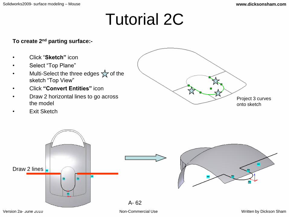
Tutorial 2CTo create 2nd parting surface:-
• Click “Sketch” icon
• Select “Top Plane”
• Multi-Select the three edges of the
sketch “Top View”
• Click “Convert Entities” icon
• Draw 2 horizontal lines to go across
the model
• Exit Sketch
Project 3 curves
onto sketch
Draw 2 lines

Solidworks2009- surface modeling – Mouse
Non-Commercial Use
www.dicksonsham.com
Version 2a- June 2010 Written by Dickson Sham
A- 63
Tutorial 2C• Select “Insert/ Surface/Extrude” on
the menu bar
• Select the new sketch as profile
• Enter 50mm as D1
• Click ok
SHOW the solid body
(Do it yourself)Extrude7
Trim6
SolidBody
show

Solidworks2009- surface modeling – Mouse
Non-Commercial Use
www.dicksonsham.com
Version 2a- June 2010 Written by Dickson Sham
A- 64
Tutorial 2CTo add a fillet on the solid:-
• Click “Fillet” icon
• Select “Constant radius” as type
• Select the edge
• Enter 1mm as radius
• (Select “Tangent Propagation”)
• Click ok
To hollow the solid:-
• Click “Shell” icon
• Enter 2.5mm as D1
• (Do not pick any face of the solid)
• Click ok
File/Save
(The MASTER model is finished, and
we are going to split it into separate
parts)
Select “view/display/section view”
then select “Right Plane”, you
can see that the solid has been
hollowed

Solidworks2009- surface modeling – Mouse
Non-Commercial Use
www.dicksonsham.com
Version 2a- June 2010 Written by Dickson Sham
A- 65
Tutorial 2CTo create the upper body:-
• Select File/New
• Select Part as type
• Click ok
• Select “Insert/Part…” on the top menu
• Select “Mouse_Mastermodel_a.sldprt”
• Click Open
• Select “Surface bodies” under the list of
“Transfer”
• Click ok (or Press Enter key to complete)
(Remark: All Surfaces of MasterModel will be copied
and pasted onto this new part!)
(Remark: On the tree of the new part, we have three
surfaces and a solid copied from the Master. If
the master is changed, the four elements will be
updated automatically!)
(Remark: If you right-click on “Mastermodel” and select
“List External Refs…”, you can see that the
bodies have been linked to an external file
“Mouse_Mastermodel_a.sldprt”)
NEW PART
Solid & Surfaces
from Master Model

Solidworks2009- surface modeling – Mouse
Non-Commercial Use
www.dicksonsham.com
Version 2a- June 2010 Written by Dickson Sham
A- 66
Tutorial 2C• Select “Insert / Surface/ Offset” on the menu bar
• Select “Surface-Extrude7” on tree (all faces will
be selected)
• Enter 0.5mm as value
• Click “Reverse Direction” icon to make the offset
inward
• Click ok
• Select “Insert / Cut / With Surface” on the menu
bar
• Select “ Offset1”
• Click “Reverse Direction” icon
• Click ok

Solidworks2009- surface modeling – Mouse
Non-Commercial Use
www.dicksonsham.com
Version 2a- June 2010 Written by Dickson Sham
A- 67
Tutorial 2C• Select “Insert / Cut / With Surface” on
the menu bar again
• Select “Trim6”
• Click “Reverse Direction” icon
• Click ok
Hide All Surfaces
• Click “Sketch” icon
• Select Top Plane
• Draw a profile as shown
• Exit Sketch
Trim6
Use “straight slot”

Solidworks2009- surface modeling – Mouse
Non-Commercial Use
www.dicksonsham.com
Version 2a- June 2010 Written by Dickson Sham
A- 68
Tutorial 2C• Click “Extruded Boss/Base” icon
• Select the new sketch
• Select “Offset” in the box “From”
• Enter 16.5mm
• Enter 33.5mm as D1 (Direction1)
• Deselect “Merge Result”
• Click ok
The Extruded solid
body is not added
onto the main body
Result: 2 solids

Solidworks2009- surface modeling – Mouse
Non-Commercial Use
www.dicksonsham.com
Version 2a- June 2010 Written by Dickson Sham
A- 69
Tutorial 2C• Click “Draft” icon
• Select “Neutral Plane” as Type of Draft
• Enter 20deg as Angle
• Select the side planar face as Neutral
Plane
• Click “Reverse Direction “ to make the
arrow point backwards
• Select the bottom face as Face to Draft
• Click ok
• Click “ Shell” icon
• Enter 1.5mm as D1 (wall thickness)
• Select the top face as “face to remove”
• Click ok
Face to draft
Neutral
Plane
Face to remove

Solidworks2009- surface modeling – Mouse
Non-Commercial Use
www.dicksonsham.com
Version 2a- June 2010 Written by Dickson Sham
A- 70
Tutorial 2C• Select “Insert / Surface / Offset” on the
menu bar
• Select the two faces of the main solid
• Enter 0mm as offset direction
• Click ok
• Select “ Insert / Cut / With Surface” on the
menu bar
• Click “Reverse Direction” to make the arrow
point upward
• Deselect “Auto-select”
• Select the solid “Shell1”
• Click ok
• Hide the cut solid & the offset surface
Solid-shell1
Surface-
Offset1

Solidworks2009- surface modeling – Mouse
Non-Commercial Use
www.dicksonsham.com
Version 2a- June 2010 Written by Dickson Sham
A- 71
Tutorial 2C• Click “ Extruded Cut” icon;
• Select “Sketch1”
• Click “Reverse Direction” to make the arrow
point upward
• Select “Through all” as D1
• Click ok
• Select “Insert / Features/ Combine” on the
menu bar
• Select “Add” as Operation type
• Select the two solid bodies (one visible &
one hidden)
• Click ok
• Click “Fillet” icon
• Select the sharp edge
• Enter 1mm as radius
• Click ok
File/Save as “Upper_body_a.sldprt”
then File/Close
Two solids are
added together

Solidworks2009- surface modeling – Mouse
Non-Commercial Use
www.dicksonsham.com
Version 2a- June 2010 Written by Dickson Sham
A- 72
Tutorial 2CTo create the lower body:-
• Select File/New
• Select Part as type
• Click ok
• Insert/Part…
• Select “Mouse_Mastermodel_a.sldprt”
• Click Open
• Select “Surface Bodies” under the list of “Transfer”
• Click ok
• Select “insert/ Surface/ Offset” on the menu bar
• Select “Trim6” on tree (all faces will be selected)
• Enter 0.5mm as value (offset downward)
• Click ok
• Select “insert/ Cut/ with surface” on the menu bar
• Select the surface “Offset.1”
• Click ok
• Hide all Surfaces
File/Save as “Lower_body_a.sldprt”
then File/Close
Trim6
Create an offset
surface (0.5mm lower)

Solidworks2009- surface modeling – Mouse
Non-Commercial Use
www.dicksonsham.com
Version 2a- June 2010 Written by Dickson Sham
A- 73
Tutorial 2CTo create the Left Button:-
• Select File/New
• Select Part as type
• Click ok
• Insert/Part…
• Select “Mouse_Mastermodel_a.sldprt”
• Click Open
• Select “Surface Bodies” under the list of “Transfer”
• Click ok
• Select “insert/ Cut/ with surface” on the menu bar
• Select the surface “Extrude7”
• (The arrow should point backwards)
• Click ok
• Select “insert/ Cut/ with surface” again
• Select the surface “Trim6”
• (The arrow should point downwards)
• Click ok
• Hide all Surfaces
Trim6
Extrude7
Solidworks2009- surface modeling – Mouse
Non-Commercial Use
www.dicksonsham.com
Version 2a- June 2010 Written by Dickson Sham
A- 74
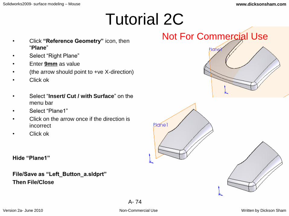
Tutorial 2C• Click “Reference Geometry” icon, then
“Plane”
• Select “Right Plane”
• Enter 9mm as value
• (the arrow should point to +ve X-direction)
• Click ok
• Select “Insert/ Cut / with Surface” on the
menu bar
• Select “Plane1”
• Click on the arrow once if the direction is
incorrect
• Click ok
Hide “Plane1”
File/Save as “Left_Button_a.sldprt”
Then File/Close
Not For Commercial Use

Solidworks2009- surface modeling – Mouse
Non-Commercial Use
www.dicksonsham.com
Version 2a- June 2010 Written by Dickson Sham
A- 75
Tutorial 2CSimilarly, create the Right button…
• Select File/New
• Select Part as type
• :
• (Ref to p.73, get the result as shown on the right)
• Click “Plane” icon
• Select “Right Plane”
• Enter 9mm as value
• (the arrow should point to -ve X-direction)
• Click ok
• Select “Insert/ Cut / with Surface” on the menu
• Select “Plane1”
• Click on the arrow once if the direction is
incorrect
• Click ok
Hide “Plane1”
File/Save as “Right_Button_a.sldprt”
Then File/Close
Solidworks2009- surface modeling – Mouse
Non-Commercial Use
www.dicksonsham.com
Version 2a- June 2010 Written by Dickson Sham
A- 76
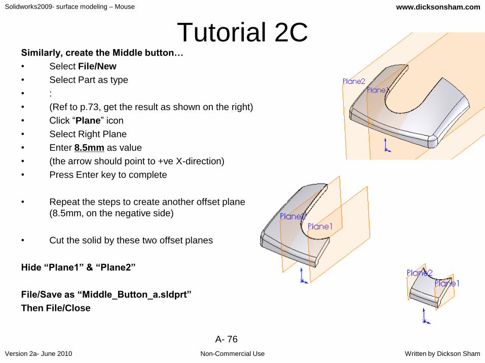
Tutorial 2CSimilarly, create the Middle button…
• Select File/New
• Select Part as type
• :
• (Ref to p.73, get the result as shown on the right)
• Click “Plane” icon
• Select Right Plane
• Enter 8.5mm as value
• (the arrow should point to +ve X-direction)
• Press Enter key to complete
• Repeat the steps to create another offset plane
(8.5mm, on the negative side)
• Cut the solid by these two offset planes
Hide “Plane1” & “Plane2”
File/Save as “Middle_Button_a.sldprt”
Then File/Close

Solidworks2009- surface modeling – Mouse
Non-Commercial Use
www.dicksonsham.com
Version 2a- June 2010 Written by Dickson Sham
A- 77
Tutorial 2CWe have split the master into separate parts. We
should always follow the rule that one file
contains one part.
Now we are going to assemble the parts into a product
• Select “File/New…” on the menu
• Click “Assembly” and then OK
To insert existing parts into the assembly:-
• Click “Browse…”
• Select the file “Lower_body_a.sldprt”
• Click “Open”
• Press Enter key to complete, or click OK
• Click “Insert Components” icon, repeat insert
other parts:
– Upper_body_a.sldprt
– Left_button_a.sldprt
– Middle_button_a.sldprt
– Right_button_a.sldprt

Solidworks2009- surface modeling – Mouse
Non-Commercial Use
www.dicksonsham.com
Version 2a- June 2010 Written by Dickson Sham
A- 78
Tutorial 2C• Download Scroll_button_a.CATpart on web:
http://myweb.polyu.edu.hk/~mmdsham/Ex2.htm
• Save it into your project folder.
• Click “Insert Components” icon
• Select the file, click Open
• Drop the part next to the assembly as shown
• Drag the part above the assembly by using
these two commands “Move component” and
“Rotate Component”
• (Remark: the scroll button is not symmetric,
the side with a hole should be closer to the
center of the mouse)
Drop here
A small hole
Solidworks2009- surface modeling – Mouse
Non-Commercial Use
www.dicksonsham.com
Version 2a- June 2010 Written by Dickson Sham
A- 79
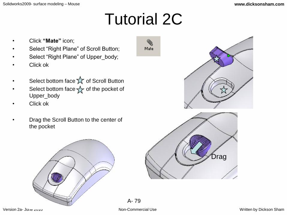
Tutorial 2C• Click “Mate” icon;
• Select “Right Plane” of Scroll Button;
• Select “Right Plane” of Upper_body;
• Click ok
• Select bottom face of Scroll Button
• Select bottom face of the pocket of
Upper_body
• Click ok
• Drag the Scroll Button to the center of
the pocket
Drag
Solidworks2009- surface modeling – Mouse
Non-Commercial Use
www.dicksonsham.com
Version 2a- June 2010 Written by Dickson Sham
A- 80
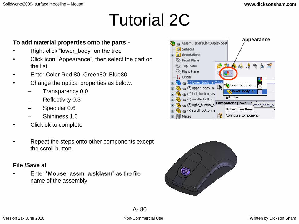
Tutorial 2CTo add material properties onto the parts:-
• Right-click “lower_body” on the tree
• Click icon “Appearance”, then select the part on
the list
• Enter Color Red 80; Green80; Blue80
• Change the optical properties as below:
– Transparency 0.0
– Reflectivity 0.3
– Specular 0.6
– Shininess 1.0
• Click ok to complete
• Repeat the steps onto other components except
the scroll button.
File /Save all
• Enter “Mouse_assm_a.sldasm” as the file
name of the assembly
appearance

Solidworks2009- surface modeling – Mouse
Non-Commercial Use
www.dicksonsham.com
Version 2a- June 2010 Written by Dickson Sham
A- 81
Tutorial 2CThe outlook of the mouse is controlled by the
Master Model. If we make any change on it,
the linked parts will be updated
automatically. Also, because all
components are created from one model,
their surfaces & boundaries can match
among themselves when assembled
together.
Now we are going to modify the master
model and see what will happen
on the corresponding parts…
MasterModel
Paste with link
Paste with link
Scroll Button
PCB
Signal Cord

Solidworks2009- surface modeling – Mouse
Non-Commercial Use
www.dicksonsham.com
Version 2a- June 2010 Written by Dickson Sham
A- 82
Tutorial 2C• File/Open... Mouse_mastermodel_a.sldprt
• Right-Click “Sketch.8” on the tree (which is
under “Surface-Loft1”
• Select “Edit Sketch”
• Change “37.5mm” to “40mm”
• Exit Sketch
• (Now the mastermodel will be updated)
• Select “Window/Mouse_assm_a.sldasm”
• Click Yes to rebuild the assembly
• (All parts will then be updated automatically)
END of Tutorial 2C
40mm
Not For Commercial Use

Solidworks2009- surface modeling – Mouse
Non-Commercial Use
www.dicksonsham.com
Version 2a- June 2010 Written by Dickson Sham
A- 83
For enquiries, please contact:
Dickson S.W. Sham
Email : [email protected]
Website : http://www.dicksonsham.com
http://www.youtube.com/dicksham
http://www.youtube.com/dickshamold