Embed Size (px)
Citation preview

OWNER-OPERATOR/PARTS MANUAL JANUARY 2003
LMC P.O. Box 428 HWY 84 West
Donalsonville, GA 39845 229-524-2197 1-800-332-8232
FAX 229-524-2531
ALLEN® 8803 UNITIZED TWIN HAY RAKE
LMC www.lmcarter.com
69-2000-88

MANUFACTURED BY:
LMC CALL: 1-800-332-8232 OR 229-524-2197
MAILING ADDRESS: P.O. BOX 428, DONALSONVILLE, GA 39845 SHIPPING ADDRESS: HWY 84 WEST, DONALSONVILLE, GA 39845
The Manufacturer reserves the right to make changes and improvements in the product at any time without notice. The Manufacturer shall not be obligated to incorporate such changes and improvements in products previously sold to any customer, nor shall the Manufacturer be obligated to replace previously sold products with customers incorporating such changes and improvements.
MACHINE IMPROVEMENTS
(ALL RIGHTS RESERVED)


Safety Messages 2-9 Description of the Rake 10 Shipping, Unloading, Site Assembly, and Delivery 11 Pre-Delivery and Delivery List 12—14 Description of Operation 15 Jack Operation, Hitching and Unhitching 16 Frame Height 17 Transporting the rake 18—19
Motor reversal, Hydraulic raking functions 20—21
Manual raking adjustments: Basket angle, Basket Tilt 22—23
Tine adjustment 24—25
Raking positions ( Basket Configurations) 26—31
Notes 32
Operation of the LMC 8803 Rake 33
Start-up 34—35
Operation (raking hay) 36—38
Shutdown 39
Emergency Procedures 40—42
The LMC basket rake hydraulic system 43
Understanding the LMC rake hydraulic system 44—54
Adjusting the LMC rake hydraulic system 56—68
Maintenance 69
Various Maintenance Procedures 70—86
Wiring Diagram, Electric Rake 87
Trouble Shooting 88
Parts Listing 89—112
Warranty Registration Card
Warranty
LMC 8803 RAKE OPERATORS MANUAL
1

SAFETY SYMBOLS
RECOGNIZE SAFETY INFORMATION
This is the safety symbol. When you see this, it means:
Follow recommended precautions and procedures:
ATTENTION! BECOME ALERT! YOUR SAFETY IS INVOLVED!
UNDERSTAND SIGNAL WORDS
A signal word —DANGER, WARNING, or CAUTION— is used with the safety-alert symbol. DANGER indicates imminently hazardous situations that, if not avoided, will result in serious injury, or death. WARNING indicates potentially hazardous situations that, if not avoided, could result in serious injury, or death. WARNING may also be used to alert against unsafe practices. CAUTION indicates potentially hazardous situations that, if not avoided, could result in minor or moderate injury. CAUTION may also be used to alert against unsafe practices.
DANGER
CAUTION
WARNING
FOLLOW SAFETY INSTRUCTIONS Carefully read all safety messages in this manual and on your machine safety signs. Keep safety signs in good condition. Remove missing or damaged safety signs. Contact LMC for replace-ment parts. Learn how to operate the machine and how to use controls properly. Do not let anyone operate without instruction. Keep your machine in proper working condition. Unauthorized modifications to the machine or disrepair may impair safety, or the machine function.
2

SAFETY PRECAUTIONS
3
ACCIDENTS CAN BE PREVENTED Without the complete cooperation of the implement operator, no accident prevention program can be successful. The operator anticipating the results before an accident occurs and taking ac-tion to remedy the situation can prevent many accidents. No power driven equipment, whether it be for transportation or processing, whether it is used on the highway, in the field, or in the shop, can be safer than the person at the controls. If accidents are to be prevented, the operators who accept these responsibilities seriously will accomplish it. Elimination of careless acts and unsafe operation will be a help in getting your safety program off to a good start.
READ THE OPERATORS MANUAL — BE ALERT
CAUTION: BEFORE APPROACHING OR ENTERING ANY MECHANISM TO SERVICE, INSPECT, OR MAKE ADJUSTMENTS.
A. LOWER UNIT TO THE GROUND B. SHUT THE TRACTOR OFF C. LOCK THE TRACTOR’S PARKING BRAKE D. REMOVE THE KEY
PREPARE FOR EMERGENCIES Be prepared in the event of personal injury, fire, or environmental problem. Keep handy a first aid kit, tools, equipment, supplies, fire extinguisher, and proper attire for han-dling chemicals associated with the machinery usage. Keep handy the emergency numbers for doctors, ambulance service, hospital, fire department, and any other emergency personnel.
WARNING: AVOID HIGH-PRESSURE FLUIDS
Escaping fluid under pressure can penetrate the skin causing serious injury. Shut off tractor before connecting or disconnecting hydraulic lines at tractor. Relieve pressure before unhooking hydraulic or other lines. Tighten all connections before applying pressure. Keep hand and body away from pinholes and components that may eject Fluids under pressure. Use a piece of cardboard to search for leaks. If ANY fluid is injected into the skin, it must be surgically removed within a few hours by a Doctor familiar with this type of injury.

4
SAFETY PRECAUTIONS
1. Never connect hydraulic lines or operate any portion of the machine unless machine is hitched to tow vehicle or tractor.
2. Do not operate hydraulic systems when hydraulic leaks are present.
3. Never ride the machine during transport or movement.
4. Always observe local traffic laws when transporting unit on public roads.
5. Always operate machine in a careful, controlled manner.
6. Personnel operating and working with this machinery and in any related duties must be properly trained and free of conditions or substances that may impair safety or good judgment.
7. Personnel operating and working with this machinery must not wear loose, dangling or unbuttoned clothing which could tangle in machinery.
8. Do not exceed 90 RPM basket speed or serious rake damage may result.
9. Always stay clear of parts that can move and entangle, pinch or crush.
10. System hydraulic pressure is to be set at minimum possible for proper operation. DO NOT EXCEED 2000 psi WORKING PRESSURE OR 2500 psi MAXIMUM PRESSURE.
11. Keep out of machine when in use.
12. Before starting machine, always check area around machine to verify that all personnel are clear.
13. Before transport or unhitching, always tie back hydraulic lines.
14. Before transport or unhitching, always tie back wires or cable with attached control panel, and place in the storage box.
15. Daily inspect fasteners for tightness (bolts, pins, etc.)
16. Always use proper procedures and equipment for handling, transporting, and storing any chemical associated with the usage of the machinery.
17. Before transport, always verify that no part of the machine can swing or slide out into the other traffic lanes, or drag on the roadway.
18. Before transport, inspect lug bolts and tire inflation.
19. Always park machine on flat ground for unhitching or storage. Before unhitching, place chocks in front and behind all transport wheels to prevent rolling when unhitched and parked.

5
SAFETY PRECAUTIONS
20. Stand clear of tongue, framework and tow vehicle or tractor when operating jack or working with hitch. Look around to be sure that if something slipped or accidentally moved that no harm would occur.
21. Always lock brakes on tractor or towing vehicle, place in parking gear, and shut off tractor or towing vehicle before working with rake jack or unhitching rake.
22. Do not attempt to use torch or welding arc around the machine when in the crop, in the field, or around other flammable items.
23. Always wear proper safety attire for each usage condition or service procedure.
24. READ AND OBSERVE SAFETY SIGNS.
25. ALWAYS USE A PROPER HITCH PIN WITH A SAFETY CLIP INSTALLED TO HITCH THE RAKE TO THE DRAWBAR OF THE TRACTOR OR TOWING VEHICLE.
26. THE EQUIPMENT DOES NOT HAVE BRAKES. DO NOT TOW AT SPEEDS OVER 20 MPH.
27. OPERATOR IS TO TURN ON FLASHING WARNING LIGHTS WHENEVER TRAVELING ON A HIGHWAY, EXCEPT WHERE SUCH USE IS PROHIBITED BY LAW.
28. MAXIMUM FIELD SPEED NOT TO EXCEED 7 MPH.

6
Safety signs must be kept legible. Replace any safety sign that becomes illegible (unreadable) or is missing.
Safety signs are supplied separately from equipment parts. It is the responsibility of the customer to purchase and affix safety signs per the equipment manufacture’s current recommendation, to any equipment part to be used during repair.
When ordering new equipment parts to be used during repair, always be sure to order any safety sign(s) to be affixed to that part. Safety signs can be ordered for LMC components from:
LMC P.O. Box 428 Donalsonville, GA 31745 Phone: 229-524-2197 800-332-8232 Fax: 229-524-2531
How to apply safety signs with self-adhesive backs:
1. Wash surface clean using a degreasing soap and water solution to remove all oil, solvent, and dust.
2. Use a square and pencil to mark decal location.
3. Using a wet cloth or spray bottle, apply a film of water to decal location.
4. Position decal and apply to equipment. Use a wet cloth or squeegee to remove air bubbles from each decal immediately after application.
SAFETY SIGNS
CUSTOMER RESPONSIBILITY
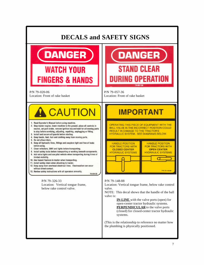
P/N 79-057-36 Location: Front of rake basket
P/N 79-020-06 Location: Front of rake basket
7
DECALS and SAFETY SIGNS
P/N 79-326-33 Location: Vertical tongue frame, below rake control valve.
P/N 79-148-88 Location: Vertical tongue frame, below rake control valve. NOTE: This decal shows that the handle of the ball valve is:
IN-LINE with the valve ports (open) for open-center tractor hydraulic systems. PERPENDICULAR to the valve ports (closed) for closed-center tractor hydraulic systems.
(This is the relationship to reference no matter how the plumbing is physically positioned.
8
DECALS and SAFETY SIGNS
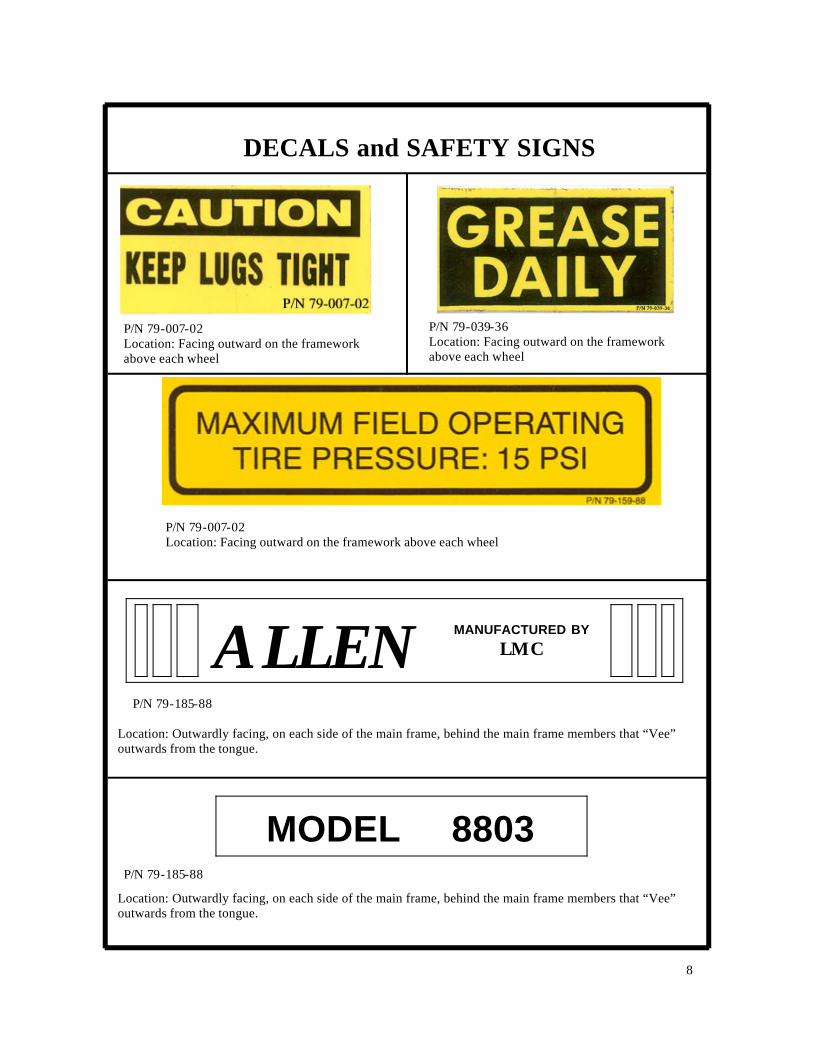
P/N 79-007-02 Location: Facing outward on the framework above each wheel
P/N 79-039-36 Location: Facing outward on the framework above each wheel
P/N 79-185-88
ALLEN MANUFACTURED BY
LMC
Location: Outwardly facing, on each side of the main frame, behind the main frame members that “Vee” outwards from the tongue.
MODEL 8803 P/N 79-185-88
Location: Outwardly facing, on each side of the main frame, behind the main frame members that “Vee” outwards from the tongue.
P/N 79-007-02 Location: Facing outward on the framework above each wheel

9
DECALS and SAFETY SIGNS

10
DESCRIPTION OF THE LMC 8803 RAKE
The LMC 8803 Rake is a hydraulically driven rake used in many heavy and custom applications. The unitized frame is extended outward to each side for raking hay and retracted for transport to and from the field. Hydraulic motors, allowing constant basket speed even if the tractor ground speed changes, drive the left-hand delivery and right-hand delivery baskets. Controls for the rake can be either manually operated levers or an electric control panel. The operator keeps the rake control console handy for easy access while in the tractor seat. The following V-SETUP REFERENCE applies to the standard configuration of the LMC/ALLEN 8803 RAKE.
Obtaining Assistance: We at LMC appreciate your choice of this rake. If you need assistance, you can reach LMC at: LMC P.O. Box 428 Donalsonville, GA 31745 Phone: (800) 332-8232 (229) 524-2197

11
SHIPPING, UNLOADING, SITE ASSEMBLY AND DELIVERY OF THE
LMC 8803 RAKE The LMC 8803 Rake is shipped in a partially assembled condition. Before hoisting any component from the truck or container, be sure that it is secured in a manner that will not allow accidental movement or falling.
BEFORE ATTEMPTING TO UNLOAD, ASSEMBLE, OR DELIVER THE COTTON CART, READ THE SAFETY SECTION OF THIS MANUAL. BE ESPECIALLY AWARE OF THE FOLLOWING PRECAUTIONS:
CAUTION
? Always wear proper safety attire for each usage condition or service procedure.
? During unloading and assembly, always stand clear. Look around to be sure that if something slipped or accidentally moved that no harm would occur.
? Stand clear of tongue, framework and tow vehicle or tractor when operating jack or working with hitch. Look around to be sure that if something slipped or accidentally moved that no harm would occur.
? Before transport, inspect lugs bolts and tire inflation
? Before transport, always verify that no part of the machine can swing or slide out into other traffic lanes or drag on the roadway.
Pictures and instructions can be found throughout this manual to assist in the required site assembly. Refer to the transport instructions in the manual prior to delivery of the Cotton Cart to the customer or work site. See the Delivery Checklist prior to delivery or operation of the rake. (Next Page)
12
PRE-DELIVERY AND DELIVERY LIST FOR THE DEALER, CUSTOMER, AND OPERATOR
LMC 8803 RAKE
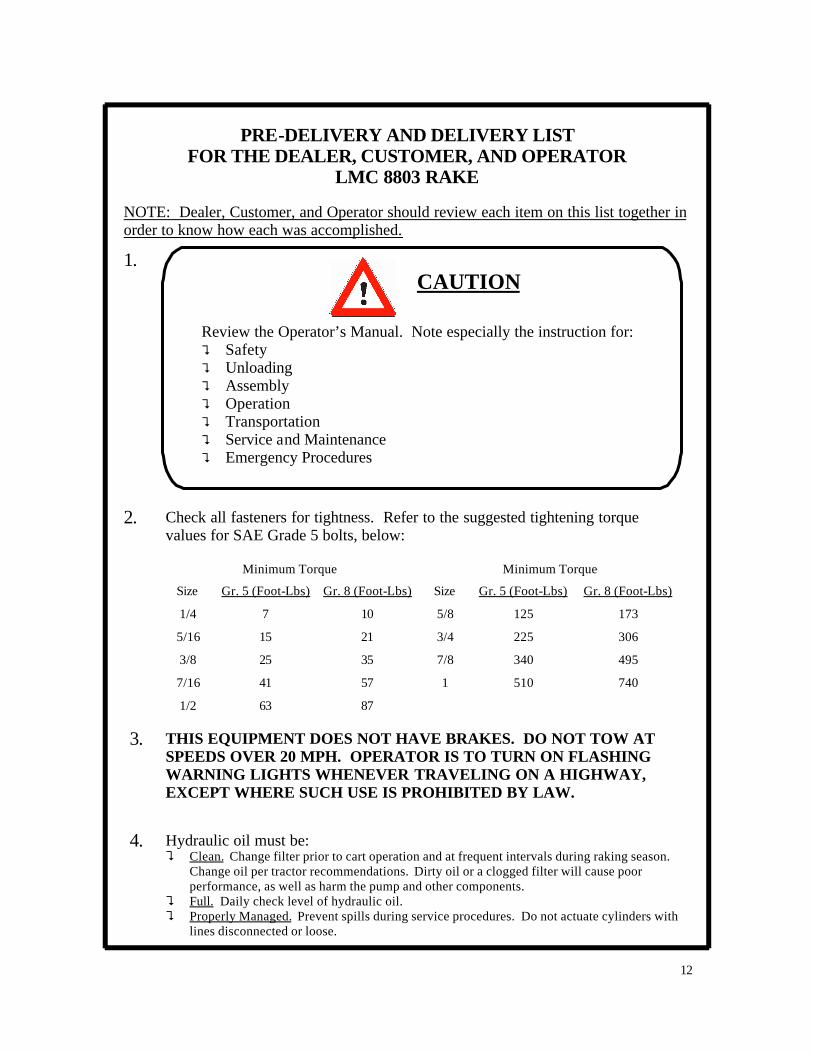
NOTE: Dealer, Customer, and Operator should review each item on this list together in order to know how each was accomplished.
Review the Operator’s Manual. Note especially the instruction for: ? Safety ? Unloading ? Assembly ? Operation ? Transportation ? Service and Maintenance ? Emergency Procedures
CAUTION 1.
2. Check all fasteners for tightness. Refer to the suggested tightening torque values for SAE Grade 5 bolts, below:
Minimum Torque
Size Gr. 5 (Foot-Lbs) Size Gr. 5 (Foot-Lbs)
1/4 7 5/8 125
5/16 15 3/4 225
3/8 25 7/8 340
7/16 41 1 510
1/2 63
Minimum Torque
Gr. 8 (Foot-Lbs)
10
21
35
57
87
Gr. 8 (Foot-Lbs)
173
306
495
740
3. THIS EQUIPMENT DOES NOT HAVE BRAKES. DO NOT TOW AT SPEEDS OVER 20 MPH. OPERATOR IS TO TURN ON FLASHING WARNING LIGHTS WHENEVER TRAVELING ON A HIGHWAY, EXCEPT WHERE SUCH USE IS PROHIBITED BY LAW.
4. Hydraulic oil must be: ? Clean. Change filter prior to cart operation and at frequent intervals during raking season.
Change oil per tractor recommendations. Dirty oil or a clogged filter will cause poor performance, as well as harm the pump and other components.
? Full. Daily check level of hydraulic oil. ? Properly Managed. Prevent spills during service procedures. Do not actuate cylinders with
lines disconnected or loose.

13
PRE-DELIVERY AND DELIVERY LIST FOR THE DEALER, CUSTOMER, AND OPERATOR
LMC 8803 RAKE 5.
CAUTION: BEFORE APPROACHING OR ENTERING ANY MECHANISM TO SERVICE, INSPECT, OR MAKE ADJUSTMENTS.
A. LOWER UNIT TO THE GROUND B. SHUT THE TRACTOR OFF C. LOCK THE TRACTOR’S PARKING BRAKE D. REMOVE THE KEY
Inspect rake systems (cont’d):
A. With the hydraulic hoses NOT connected to the tractor, turn the rake disc by hand. All parts should move freely. Tines should clear the stripper bars by at least 1/2”. If a stripper bar ahs become bent in shipment, then straighten using the rake hickey bar or pipe wrench.
B. With the hydraulic hoses NOT connected to the tractor, review the hydraulic system for proper tightness of all fittings.
C. With the tractor engine shut off, connect the hydraulic hoses to the tractor. D. Read and follow the instructions in the manual for “Adjusting the LMC/ALLEN Rake Hydraulic
System” for further explanation regarding adjustments. E. Start with the rake flow control set at about 1-1/2”. Slowly and carefully turn on the tractor
hydraulics to begin operation. The rake baskets should be turning very slowly. F. With the tractor safely parked and while keeping clear of the rake, visually inspect for loose
parts and hydraulic leaks. Should there be any problems, follow all safety procedures, especially the messages given with this step and remedy the problem.
WARNING: AVOID HIGH-PRESSURE FLUIDS
1. Escaping fluid under pressure can penetrate the skin causing serious injury. 2. Shut off tractor before connecting or disconnecting hydraulic lines at tractor. 3. Relieve pressure before unhooking hydraulic or other lines. Tighten all connections be-
fore applying pressure. Keep hand and body away from pinholes and components that may eject fluids under pressure. Use a piece of cardboard to search for leaks.
4. If ANY fluid is injected into the skin, a doctor familiar with this type of injury must surgi-cally remove it within a few hours.
CAUTION
Never place or insert anything in basket or other moving parts during operation. DO NOT EXCEED 2200 psi WORKING PRESSURE or 2500 psi MAXIMUM PRESSURE. System hydraulic pressure is to be set at minimum possible for proper operation.
6. Tractor requirements: Nine (9) gallons per minute continuous flow.
14
PRE-DELIVERY AND DELIVERY LIST FOR THE DEALER, CUSTOMER, AND OPERATOR
LMC COTTON CART
NOTE: Dealer, Customer, and Operator should review each item on this list together in order to know how each was accomplished.
7. Warranty Registration:
Customer must complete and send in the warranty registration card that is attached to the back of the manual. Warranty validation will not occur unless warranty registration cart is returned to:
LMC P.O. Box 428 Donalsonville, GA 31745 Attn: Warranty Department Phone: (229) 524-2197 (800) 332-8232
8. Record the serial number here for future reference. Serial Number: __________________________________________________
(PHOTOCOPY THIS PAGE)
(PHOTOCOPY THIS PAGE)
LMC welcomes any comments regarding the condition of the rake upon arrival at the dealership or farm. Comments: _____________________________________________________________________________________________________________________________________________________________________________________________________________________________________________________________________________________________________________________________________________________________________________________________________________________________________________________________________________________ Signature: Mail to: LMC , P.O. Box 428, Donalsonville, GA 31745
15
SETUP AND DESCRIPTION OF CONTROLS LMC 8803 RAKE
CAUTION
Read all SAFETY MESSAGES at the beginning of this manual before attempting any of the procedures described in this section.
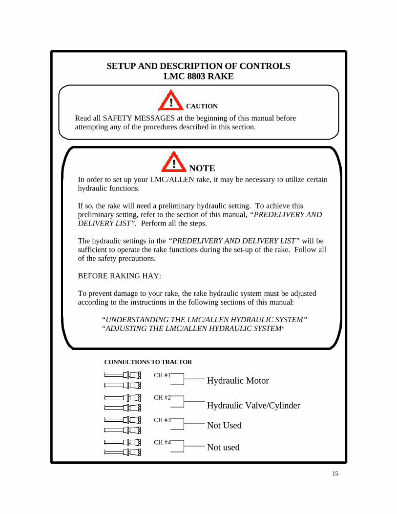
NOTE In order to set up your LMC/ALLEN rake, it may be necessary to utilize certain hydraulic functions. If so, the rake will need a preliminary hydraulic setting. To achieve this preliminary setting, refer to the section of this manual, “PREDELIVERY AND DELIVERY LIST”. Perform all the steps. The hydraulic settings in the “PREDELIVERY AND DELIVERY LIST” will be sufficient to operate the rake functions during the set-up of the rake. Follow all of the safety precautions. BEFORE RAKING HAY: To prevent damage to your rake, the rake hydraulic system must be adjusted according to the instructions in the following sections of this manual: “UNDERSTANDING THE LMC/ALLEN HYDRAULIC SYSTEM” “ADJUSTING THE LMC/ALLEN HYDRAULIC SYSTEM”
CH #1
CONNECTIONS TO TRACTOR
CH #3
CH #4
CH #2
Hydraulic Motor
Hydraulic Valve/Cylinder
Not Used
Not used

16
JACK OPERATION LMC 8803 RAKE
CAUTION
Stand clear of tongue, framework and tow vehicle or tractor when operating jack or working with hitch. Look around to be sure that if something slipped or accidentally moved that no harm would occur. Always park machine on flat ground for unhitching or storage. Before unhitching, place chocks in front and behind all transport wheels to prevent rolling when unhitched and parked. Always lock brakes on tractor or tow vehicle, place in parking gear and shut off tractor or vehicle before working with the rake jack or unhitching rake.
ALWAYS USE A PROPER HITCH PIN WITH A SAFETY CLIP INSTALLED TO HITCH THE RAKE TO THE DRAWBAR OF THE TRACTOR OR TOWING VEHICLE. (See figure, next page.)
Read the following safety precautions, then sequentially follow the instructions given below. A pictorial reference is provided.
HITCHING Using the jack’s crank handle, raise or lower the rake tongue to align the rake hitch with the draw-bar of the tractor or tow vehicle. Securely hitch rake to tractor using a proper hitch pin with a safety clip installed. Use t he jack’s crank handle to take the pressure off of the jack foot. Pull the jack foot pin and push the jack foot fully up inside the leg of the jack. Insert jack foot pin into the aligned holes in the leg of the jack and the raised foot. Use the jack’s crank handle to fully retract the leg of the jack to the transport position.
UNHITCHING Before unhitching the rake from the tractor or tow vehicle, pull the jack foot pin and lower the jack
foot as far as possible to have aligned holes in the side of leg and foot of the jack. Insert the jack foot pin into the aligned holes. Using the rake’s crank handle, raise the rake hitch off of the draw-bar of the tractor or tow vehicle. After chocking front and back of the rake wheels, unhitch the rake.
17
FRAME HEIGHT LMC 8803 RAKE
CAUTION
Stand clear of tongue, framework and tow vehicle or tractor when operating jack or working with hitch. Look around to be sure that if something slipped or accidentally moved that no harm would occur. Always lock brakes on tractor or tow vehicle, place in parking gear and shut off tractor or vehicle before working with the rake jack or unhitching rake.
ALWAYS USE A PROPER HITCH PIN WITH A SAFETY CLIP INSTALLED TO HITCH THE RAKE TO THE DRAWBAR OF THE TRACTOR OR TOWING VEHICLE.
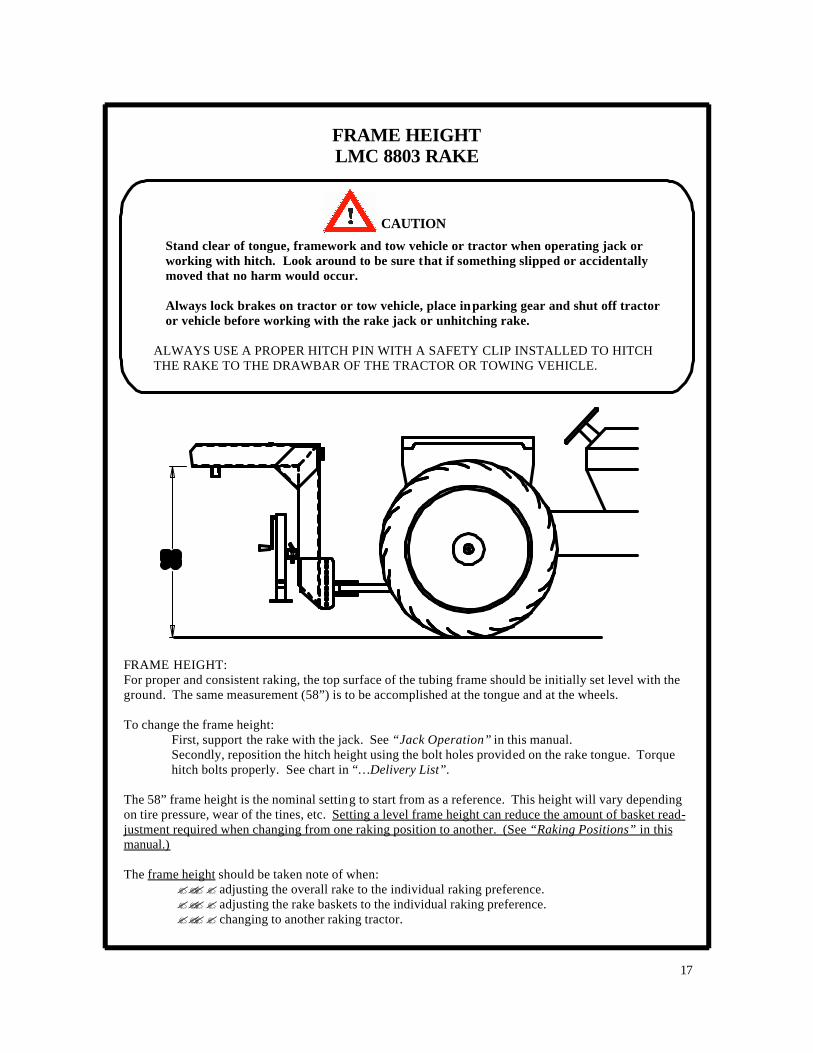
FRAME HEIGHT: For proper and consistent raking, the top surface of the tubing frame should be initially set level with the ground. The same measurement (58”) is to be accomplished at the tongue and at the wheels. To change the frame height:
First, support the rake with the jack. See “Jack Operation” in this manual. Secondly, reposition the hitch height using the bolt holes provided on the rake tongue. Torque hitch bolts properly. See chart in “…Delivery List”.
The 58” frame height is the nominal setting to start from as a reference. This height will vary depending on tire pressure, wear of the tines, etc. Setting a level frame height can reduce the amount of basket read-justment required when changing from one raking position to another. (See “Raking Positions” in this manual.) The frame height should be taken note of when:
???? adjusting the overall rake to the individual raking preference. ???? adjusting the rake baskets to the individual raking preference. ???? changing to another raking tractor.

18
TRANSPORTATION LMC 8803 RAKE
CAUTION
Read all safety instructions at the beginning of the manual. Especially regard the following: ALWAYS USE A PROPER HITCH PIN WITH A SAFETY CLIP INSTALLED TO HITCH THE RAKE TO THE DRAWBAR OF THE TRACTOR OR TOWING VEHICLE. THIS EQUIPMENT DOES NOT HAVE BRAKES. DO NOT TOW AT SPEEDS OVER 20 MPH. OPERATOR IS TO TURN ON FLASHING WARNING LIGHTS WHENEVER TRAVELING ON A HIGHWAY, EXCEPT WHERE SUCH USE IS PROHIBITED BY LAW. Never connect hydraulic lines or operate any portion of the machine unless machine is hitched to tow ve-hicle or tractor. Never ride on the machine during transport or movement. Always observe local traffic laws when transporting unit on public roads. Personnel operating and working with this machinery and in any related duties must be properly trained and free of conditions or substances that may impair safety or good judgment. Before transport or unhitching, always tie back hydraulic hoses. Before transport or unhitching, always tie back wires or cable with attached control panel and place in the storage box. Before transport, always verify that no part of the machine can swing or slide out into other traffic lanes or drag on the roadway. Before transport, inspect lug bolts and tire inflation. Always park machine on flat ground for unhitching or storage. Before unhitching, place chocks in front and behind all transport wheels to prevent rolling when unhitched and parked. Stand clear of tongue, framework and tow vehicle or tractor when operating jack or working with hitch. Look around to be sure that of something slipped or accidentally moved that no harm would occur. Always lock brakes on tractor or tow vehicle, place in parking gear and shut off tractor or vehicle before working with the rake jack or unhitching rake. TRANSPORTING INSTRUCTIONS: While following safety procedures, put the rake into the compact transport position, as shown on the next page. Drive slowly (20 mph or less). Drive carefully, always being aware of the rake’s position in rela -tion to traffic and roadside objects.

19
TRANSPORTATION LMC 8803 RAKE
TOP VIEW

20
MOTOR REVERSAL CONTROLS: HYDRAULIC RAKING FUNCTIONS
LMC BASKET RAKE
CAUTION
Read all Safety Messages at the beginning of this manual before attempting any of the procedures described in this section.
Regard especially the following:
BEFORE APPROACHING OR ENTERING ANY MECHANISM TO SERVICE, INSPECT OR MAKE ADJUSTMENTS: A. LOWER UNIT TO THE GROUND. B. SHUT THE TRACTOR OFF. C. LOCK THE TRACTOR’S PARKING BRAKE. D. REMOVE THE KEY.
CAUTION
WARNING: AVOID HIGH-PRESSURE FLUIDS
1. Escaping fluid under pressure can penetrate the skin causing serious injury. 2. Shut off tractor before connecting or disconnecting hydraulic lines at tractor. 3. Relieve pressure before unhooking hydraulic or other lines. Tighten all connections be-
fore applying pressure. Keep hand and body away from pinholes and components that may eject fluids under pressure. Use a piece of cardboard to search for leaks.
4. If ANY fluid is injected into the skin, a doctor familiar with this type of injury must surgi-cally remove it within a few hours.
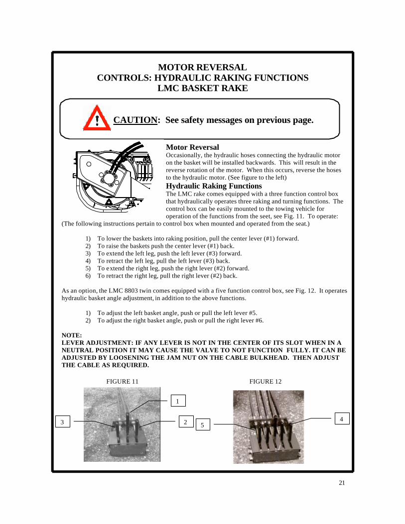
Motor Reversal Occasionally, the hydraulic hoses connecting the hydraulic motor on the basket will be installed backwards. This will result in the reverse rotation of the motor. When this occurs, reverse the hoses to the hydraulic motor. (See figure to the left) Hydraulic Raking Functions The LMC rake comes equipped with a three function control box that hydraulically operates three raking and turning functions. The control box can be easily mounted to the towing vehicle for operation of the functions from the seet, see Fig. 11. To operate:
(The following instructions pertain to control box when mounted and operated from the seat.)
1) To lower the baskets into raking position, pull the center lever (#1) forward. 2) To raise the baskets push the center lever (#1) back. 3) To extend the left leg, push the left lever (#3) forward. 4) To retract the left leg, pull the left lever (#3) back. 5) To extend the right leg, push the right lever (#2) forward. 6) To retract the right leg, pull the right lever (#2) back.
As an option, the LMC 8803 twin comes equipped with a five function control box, see Fig. 12. It operates hydraulic basket angle adjustment, in addition to the above functions.
1) To adjust the left basket angle, push or pull the left lever #5. 2) To adjust the right basket angle, push or pull the right lever #6.
NOTE: LEVER ADJUSTMENT: IF ANY LEVER IS NOT IN THE CENTER OF ITS SLOT WHEN IN A NEUTRAL POSITION IT MAY CAUSE THE VALVE TO NOT FUNCTION FULLY. IT CAN BE ADJUSTED BY LOOSENING THE JAM NUT ON THE CABLE BULKHEAD. THEN ADJUST THE CABLE AS REQUIRED.
21
MOTOR REVERSAL CONTROLS: HYDRAULIC RAKING FUNCTIONS
LMC BASKET RAKE
CAUTION: See safety messages on previous page.
FIGURE 11
1
2 3
FIGURE 12
4 5

22
MANUAL RAKING ADJUSTMENTS BASKET ANGLE AND BASKET TILT
LMC BASKET RAKE
CAUTION
Read all Safety Messages at the beginning of this manual before attempting any of the procedures described in this section.
Regard especially the following:
BEFORE APPROACHING OR ENTERING ANY MECHANISM TO SERVICE, INSPECT OR MAKE ADJUSTMENTS: A. LOWER UNIT TO THE GROUND. B. SHUT THE TRACTOR OFF. C. LOCK THE TRACTOR’S PARKING BRAKE. D. REMOVE THE KEY Stay clear of the tines and framework. Look around to be sure that if something slipped or accidentally moved, no harm would occur.
CAUTION

NOTE: BEFORE MAKING ANY OF THE FOLLOWING ADJUSTMENTS, LOWER THE BASKETS AS ILLUSTRAED IN FIGURE 11—HYDRAULIC RAKING FUNCTIONS. THIS WILL PREVENT DAMMAGE TO THE FRAME AND MAKE IT EASIER TO MAKE THE ADJUSTMENTS. Manual Raking Adjustments Basket angle: To adjust the angle of the basket, remove the keeper pin and swing the basket until the desired angle is found then replace the pin. NOTE: MANUAL ADJUSTMENT OF THE BASKET ANGLE IS FOUND ONLY ON RAKES WITH THREE (3) FUNCTION CONTROL BOXES. Basket Tilt: The rake also comes equipped with a screw adjustment bar to position the tilt of the basket in relation to the ground.
1) Loosen the locking device. 2) Turn the bar for desired basket tilt. 3) When the basket is perpendicular to
the ground, a loose fluffy windrow is made.
4) When the basket is tilted forward to the ground a tight, more compact windrow is made.
5) Tighten the locking device.
23
BASKET ANGLE AND BASKET TILT LMC BASKET RAKE
CAUTION: See safety messages on previous page.
24
TINE ADJUSTMENT LMC BASKET RAKE
CAUTION
Read all Safety Messages at the beginning of this manual before attempting any of the procedures described in this section.
Regard especially the following:
BEFORE APPROACHING OR ENTERING ANY MECHANISM TO SERVICE, INSPECT OR MAKE ADJUSTMENTS: A. LOWER UNIT TO THE GROUND. B. SHUT THE TRACTOR OFF. C. LOCK THE TRACTOR’S PARKING BRAKE. D. REMOVE THE KEY Stay clear of the tines and framework. Look around to be sure that if something slipped or accidentally moved, no harm would occur.
CAUTION
PREPARING FOR TINE ADJUSTMENT Following all safety instructions the following must be accomplished before the tines can be adjusted:
1. Rake hitched to tractor. See “JACK OPERATION.” 2. Frame height set level. See “FRAME HEIGHT”. 3. Rake hydraulics set for operation. See “ADJUSTING THE LMC/ALLEN RAKE HYDRAU-
LIC SYSTEM” or Rake hydraulic given a preliminary setting. See “PREDELIVERY AND DELIVERY LIST”.
4. Rake frame and baskets positioned as actually intended for raking. See “MANUAL RAK-ING
ADJUSTMENTS”, “RAKING POSITIONS”, “HYDRAULIC RAKING FUNCTIONS”.
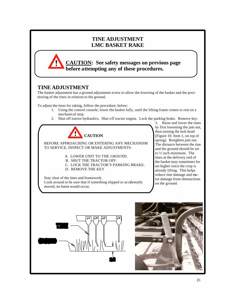
TINE ADJUSTMENT The basket adjustment has a ground adjustment screw to allow the lowering of the basket and the posi-tioning of the tines in relation to the ground. To adjust the tines for raking, follow the procedure, below:
1. Using the control console, lower the basket fully, until the lifting frame comes to rest on a mechanical stop.
2. Shut off tractor hydraulics. Shut off tractor engine. Lock the parking brake. Remove key. 3. Raise and lower the tines by first loosening the jam nut, then turning the bolt head (Figure 16: Item 1, on top of spring). Retighten jam nut. The distance between the tine and the ground should be set to ½ inch minimum. The tines at the delivery end of the basket may sometimes be set higher since the crop is already lifting. This helps reduce tine damage and mo-tor damage from obstructions on the ground.
25
TINE ADJUSTMENT LMC BASKET RAKE
BEFORE APPROACHING OR ENTERING ANY MECHANISM TO SERVICE, INSPECT OR MAKE ADJUSTMENTS: A. LOWER UNIT TO THE GROUND. B. SHUT THE TRACTOR OFF. C. LOCK THE TRACTOR’S PARKING BRAKE. D. REMOVE THE KEY Stay clear of the tines and framework. Look around to be sure that if something slipped or accidentally moved, no harm would occur.
CAUTION
CAUTION: See safety messages on previous page before attempting any of these procedures.
26
RAKING POSITIONS LMC BASKET RAKE
CAUTION
Read all SAFETY MESSAGES at the beginning of this manual before attempting any of the procedures described in this section.
Regard especially the following: BEFORE APPROACHING OR ENTERING ANY MECHANISM TO SERVICE, INSPECT, OR MAKE ADJUSTMENTS:
A. LOWER UNIT TO THE GROUND. B. SHUT THE TRACTOR OFF. C. LOCK THE TRACTOR’S PARKING BRAKE. D. REMOVE THE KEY.
STAND CLEAR Look around to be sure that if something slipped or accidentally moved that no harm would occur. Personnel operating and working with machinery must not wear loose, dangling or unbuttoned clothing that could tangle in machinery.
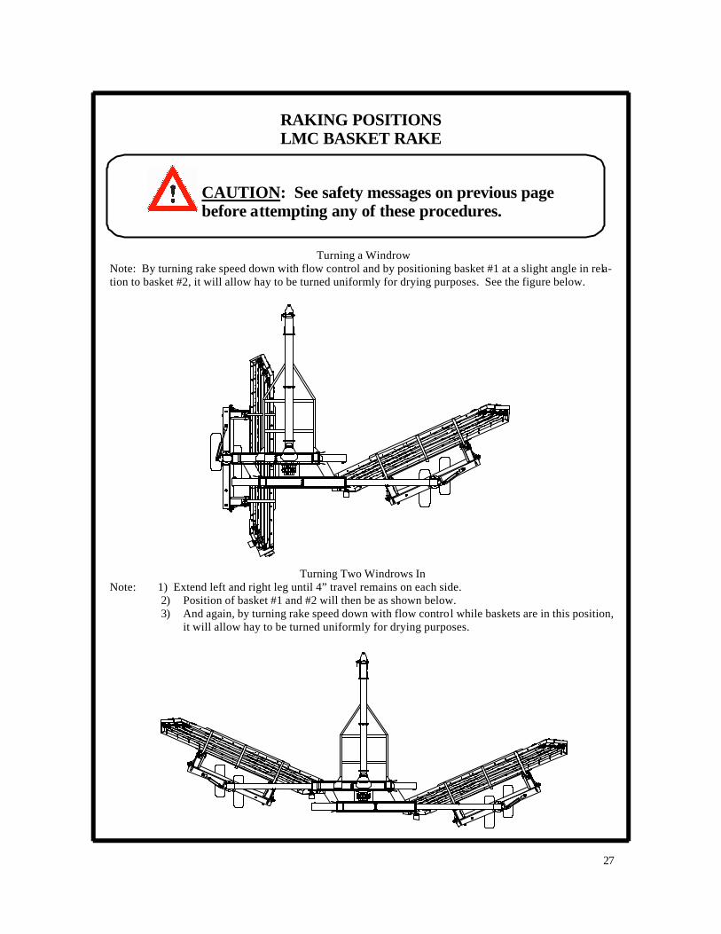
Turning a Windrow Note: By turning rake speed down with flow control and by positioning basket #1 at a slight angle in rela-tion to basket #2, it will allow hay to be turned uniformly for drying purposes. See the figure below.
Turning Two Windrows In
Note: 1) Extend left and right leg until 4” travel remains on each side. 2) Position of basket #1 and #2 will then be as shown below. 3) And again, by turning rake speed down with flow control while baskets are in this position,
it will allow hay to be turned uniformly for drying purposes.
27
RAKING POSITIONS LMC BASKET RAKE
CAUTION: See safety messages on previous page before attempting any of these procedures.

28
RAKING POSITIONS LMC BASKET RAKE
CAUTION
Read all SAFETY MESSAGES at the beginning of this manual before attempting any of the procedures described in this section.
Regard especially the following: BEFORE APPROACHING OR ENTERING ANY MECHANISM TO SERVICE, INSPECT, OR MAKE ADJUSTMENTS:
A. LOWER UNIT TO THE GROUND. B. SHUT THE TRACTOR OFF. C. LOCK THE TRACTOR’S PARKING BRAKE. D. REMOVE THE KEY.
STAND CLEAR Look around to be sure that if something slipped or accidentally moved that no harm would occur. Personnel operating and working with machinery must not wear loose, dangling or unbuttoned clothing that could tangle in machinery.
The LMC 8803 Rake is equipped with a variety of adjustments to give the operator the flexibility to handle light or heavy cuttings, to make fluffy or tight windrows, to turn two windrows, to combine several windrows, etc.
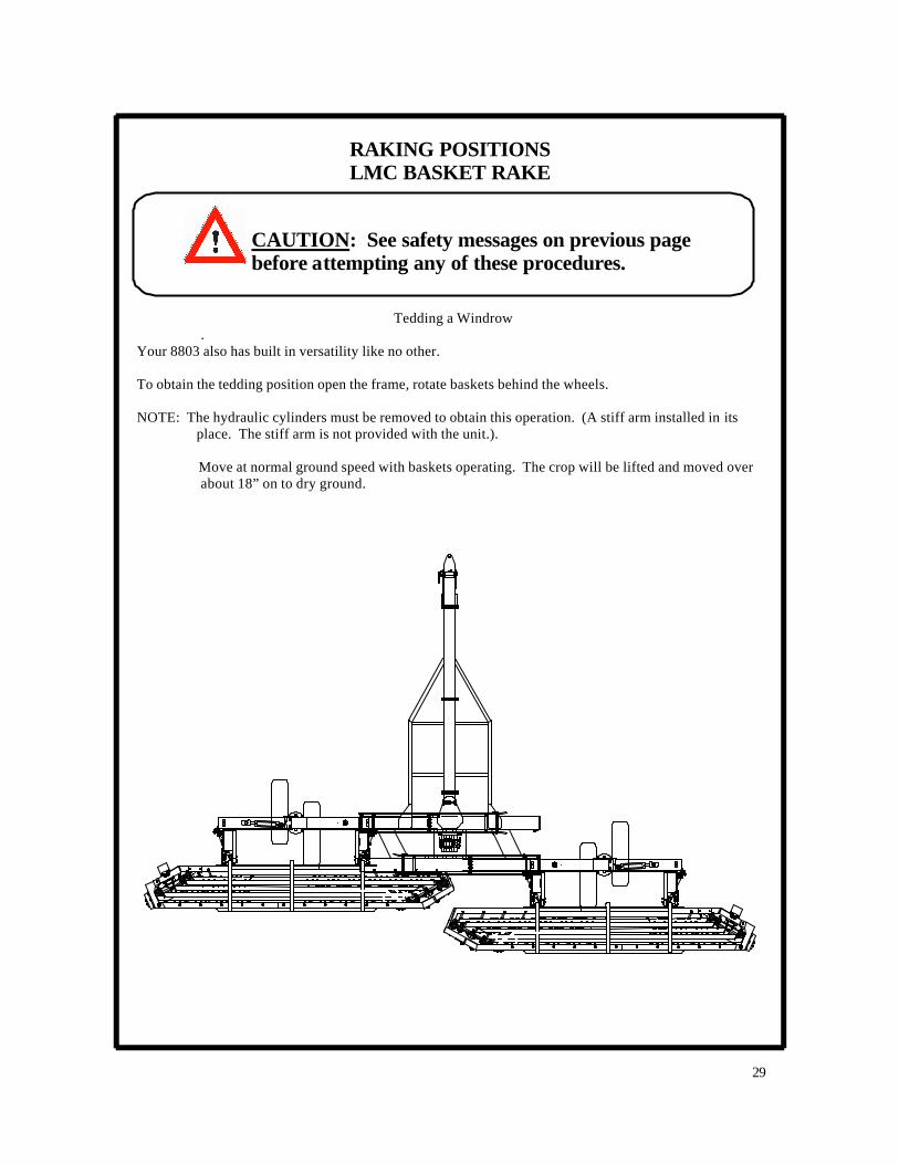
Tedding a Windrow .
Your 8803 also has built in versatility like no other. To obtain the tedding position open the frame, rotate baskets behind the wheels. NOTE: The hydraulic cylinders must be removed to obtain this operation. (A stiff arm installed in its
place. The stiff arm is not provided with the unit.).
Move at normal ground speed with baskets operating. The crop will be lifted and moved over about 18” on to dry ground.
29
RAKING POSITIONS LMC BASKET RAKE
CAUTION: See safety messages on previous page before attempting any of these procedures.

30
RAKING POSITIONS LMC BASKET RAKE
Read all SAFETY MESSAGES at the beginning of this manual before attempting any of the procedures described in this section.
Regard especially the following: BEFORE APPROACHING OR ENTERING ANY MECHANISM TO SERVICE, INSPECT, OR MAKE ADJUSTMENTS:
A. LOWER UNIT TO THE GROUND. B. SHUT THE TRACTOR OFF. C. LOCK THE TRACTOR’S PARKING BRAKE. D. REMOVE THE KEY.
STAND CLEAR Look around to be sure that if something slipped or accidentally moved that no harm would occur. Personnel operating and working with machinery must not wear loose, dangling or unbuttoned clothing that could tangle in machinery.
CAUTION
The LMC 8803 Rake is equipped with a variety of adjustments to give the operator the flexibility to handle light or heavy cuttings, to make fluffy or tight windrows, to turn two windrows, to combine several windrows, etc.
WARNING: AVOID HIGH-PRESSURE FLUIDS
1. Escaping fluid under pressure can penetrate the skin causing serious injury. 2. Shut off tractor before connecting or disconnecting hydraulic lines at tractor. 3. Relieve pressure before unhooking hydraulic or other lines. Tighten all connections be-
fore applying pressure. Keep hand and body away from pinholes and components that may eject fluids under pressure. Use a piece of cardboard to search for leaks.
4. If ANY fluid is injected into the skin, a doctor familiar with this type of injury must surgi-cally remove it within a few hours.
31
RAKING POSITIONS LMC BASKET RAKE
CAUTION: See safety messages on previous page before attempting any of these procedures.
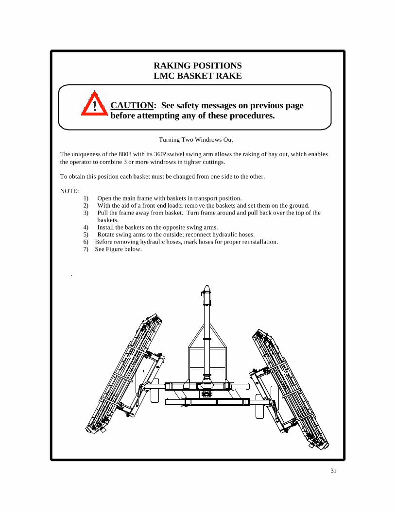
Turning Two Windrows Out The uniqueness of the 8803 with its 360? swivel swing arm allows the raking of hay out, which enables the operator to combine 3 or more windrows in tighter cuttings. To obtain this position each basket must be changed from one side to the other. NOTE:
1) Open the main frame with baskets in transport position. 2) With the aid of a front-end loader remo ve the baskets and set them on the ground. 3) Pull the frame away from basket. Turn frame around and pull back over the top of the
baskets. 4) Install the baskets on the opposite swing arms. 5) Rotate swing arms to the outside; reconnect hydraulic hoses. 6) Before removing hydraulic hoses, mark hoses for proper reinstallation. 7) See Figure below.

32
NOTES

33
OPERATION OF THE
LMC 8803 RAKE
TOPICS:
START-UP
OPERATION
SHUT-DOWN
EMERGENCY PROCEDURES

34
STARTUP LMC 8803 RAKE
ACCIDENTS CAN BE PREVENTED Without the complete cooperation of the implement operator, no accident prevention program can be successful. The operator anticipating the results before an accident occurs and taking ac-tion to remedy the situation can prevent many accidents. No power driven equipment, whether it be for transportation or processing, whether it is used on the highway, in the field, or in the shop, can be safer than the person at the controls. If accidents are to be prevented, the operators who accept these responsibilities seriously will accomplish it. Elimination of careless acts and unsafe operation will be a help in getting your safety program off to a good start.
READ THE OPERATORS MANUAL – BE ALERT
CAUTION
1. Never connect hydraulic lines or operate any portion of the machine unless ma-chine is hitched to tow vehicle or tractor.
2. Do not operate hydraulic systems when hydraulic leaks are present. 3. Never ride on the machine during transport or movement. 4. Always observe local traffic laws when transporting unit on public roads. 5. Always operate machine in a careful, controlled manner. 6. Personnel operating and working with this machinery and in any related duties
must be properly trained and free of conditions or substances that may impair safety or good judgment.
7. Personnel operating and working with this machinery must not wear loose, dan-gling or unbuttoned clothing that could tangle in machinery.
8. Do not exceed 90 rpm basket speed or serious rake damage may result. 9. Always stay clear of parts that can move and entangle, pinch or crush. 10. System Hydraulic pressure is to be set at minimum possible for proper operation.
DO NOT EXCEED 2000-psi WORKING PRESSURE OR 2700 psi MAXIMUM PRESSURE.
11. Keep out of machi ne when in use. 12. Before starting machine, always check area around machine to verify that all per-
sonnel are clear. 13. Daily inspect fasteners for tightness (bolts, pins, etc.).
READ AND OBSERVE SAFETY SIGNS

35
RAKING POSITIONS LMC BASKET RAKE
CAUTION: See safety messages on previous page before attempting any of these procedures.
PREPARATION FOR START-UP Before starting the rake, the following should be accomplished: 1. Operator has reviewed and understood all of the safety messages in this manual. 2. Operator has become familiar with all of the controls and rake setting as described in this man-
ual. 3. The rake has been properly hitched to the tractor as described in the “SET-UP” section of this
manual. 4. Operator has given the rake an inspection for machine condition. 5. The rake hoses have been properly connected to the tractor remote connectors as per the section
“ADJUSTING THE LMC/ALLEN RAKE HYDRAULIC SYSTEM” in this manual. 6. The rake hydraulic system has been properly set according to the instructions in
“UNDERSTANDING THE LMC/ALLEN RAKE HYDRAULIC SYSTEM”, and “ADJUSTING THE LMC/ALLEN RAKE HYDRAULIC SYSTEM” in this manual.
7. The rake has been set, according to this manual, for: level frame, basket tilt, basket angle, and tine adjustment.
8. Tractor has been verified to have a new or clean hydraulic filter. 9. Tractor reservoir is full with clean hydraulic oil. 10. Control console has been affixed securely near convenient reach of the operator’s position in
the tractor seat.
START -UP After completion of the “PREPARATION FOR START-UP”, do the following: 1. Crank tractor and let engine idle out of gear and with tractor brake applied. 2. Slowly start the tractor remote hydraulic system per the recommended method for hydraulic
motor operation in the tractor manual. 3. Slowly increase the tractor engine speed to operational field rpm (usually 2000-2500 rpm). See
tractor manual for details. 4. The basket should be rotating at 85-90 rpm. Place the tractor in proper gear and gently begin
traveling.
36
OPERATION LMC 8803 RAKE
ACCIDENTS CAN BE PREVENTED Without the complete cooperation of the implement operator, no accident prevention program can be successful. The operator anticipating the results before an accident occurs and taking ac-tion to remedy the situation can prevent many accidents. No power driven equipment, whether it be for transportation or processing, whether it is used on the highway, in the field, or in the shop, can be safer than the person at the controls. If accidents are to be prevented, the operators who accept these responsibilities seriously will accomplish it. Elimination of careless acts and unsafe operation will be a help in getting your safety program off to a good start.
READ THE OPERATORS MANUAL – BE ALERT
1. Do not operate hydraulic systems when hydraulic leaks are present. 2. Never ride on the machine during transport or movement. 3. Always observe local traffic laws when transporting unit on public roads. 4. Personnel operating and working with this machinery and in any related du-
ties must be properly trained and free of conditions or substances that may impair safety or good judgment.
5. Personnel operating and working with this machinery must not wear loose, dangling or unbuttoned clothing that could tangle in machinery.
6. Do not exceed 90-rpm basket speed or serious rake damage may result. 7. Always stay clear of parts that can move and entangle, pinch or crush. 8. System hydraulic pressure is to be set at minimum possible for proper opera-
tion. DO NOT EXCEED 2000-psi WORKING PRESSURE OR 2700 psi MAXIMUM PRESSURE.
9. Keep out of machine when in use.
MAXIMUM FIELD SPEED NOT TO EXCEED 7 MPH. READ AND OBSERVE SAFETY SIGNS.
CAUTION
CAUTION: See safety messages on previous page before attempting any of these procedures.

37
OPERATION LMC 8803 RAKE
CAUTION: See safety messages on previous page before attempting any of these procedures.
PREPARATION FOR OPERATION To operate the rake, the steps must be completed as shown in the sections of this manual “PREPARATION FOR START-UP”, and “START-UP”. At the end of the “START-UP” proce-dures, the rake is being towed by the tractor in the field. OPERATION 1. Setting the Rake Position.
The desired “Width of Windrow” is maintained by adjusting the Basket Angle and the position of the Telescoping Extension Arms . The following relationships apply: A steeper basket angle allows a faster ground speed in heavy hay. A steeper basket angle assists gentler handling of the crop (leaf retention). A more flat basket angle allows for a wider swath. 2. If the rake has difficulty in heavy hay, the following applies:
??? Verify that the baskets are at 85-90 RPM, but no faster. ??? Have the tractor pump checked (pressure, flow rate, slippage). ??? Install the heavy-duty motors and flow control available from LMC.
3. Depress clutch to maintain engine RPM and reduce ground speed when approaching
heavy clumps of hay.
4. Remember that the baskets must be rotating for the other rake control to work.
5. Raise baskets when turning the tractor, as at the end of a swath.
38
OPERATION LMC 8803 RAKE
CAUTION: See safety messages on previous page before attempting any of these procedures.
OPERATION, (continued)
6 If basket “hairs over” with hay, then the basket RPM is likely too fast for the crop condition and ground speed.
7. If the front of the basket dips down so that the tines are contacting the ground, then there
is likely too much loose motion in the extension arms. This can be remedied by installation of Half-Shims behind the Poly-Slide Bearings. See “MAINTENANCE” Section for proper placement and installation instructions.
8. Occasionally the basket may load up with hay and stall or jam. If this occurs, utilize the following procedures: A. Allow the basket to clear itself with the operator staying in the tractor seat using a
suitable combination of the following efforts: ??? Raising the Basket. ??? Depressing the clutch to slow the tractor while maintaining engine RPM. ??? Breaking the tractor to a full stop, then slowly backing up, if necessary. ??? Starting and stopping the tractor hydraulics in order to repeatedly start and
stop the rake basket.
B. Shut off the tractor. Follow the safety procedures below.
Read all SAFETY MESSAGES at the beginning of this manual before attempting any of the procedures described in this section.
Regard especially the following: BEFORE APPROACHING OR ENTERING ANY MECHANISM TO SERVICE, INSPECT, OR MAKE ADJUSTMENTS:
A. LOWER UNIT TO THE GROUND. B. SHUT THE TRACTOR OFF. C. LOCK THE TRACTOR’S PARKING BRAKE. D. REMOVE THE KEY.
STAND CLEAR
Look around to be sure that if something slipped or accidentally moved that no harm would occur. Personnel operating and working with machinery must not wear loose, dangling or unbuttoned clothing that could tangle in machinery.
CAUTION
Very carefully, remove the jammed hay.
39
SHUTDOWN LMC 8803 RAKE
CAUTION: See safety messages on previous page before attempting any of these procedures.
.SHUT-DOWN 1. Prior to shutting off the tractor hydraulic system, operate the rake hydraulic system as
required (basket cylinders, extension arms, etc.) 2. Shut off the tractor hydraulic system. 3. Place the tractor in the proper parking gear and apply parking brake. Shut off engine. 4. Review the sections in this manual that pertain to the next anticipated function, such as:
??? SAFETY PRECAUTIONS ??? JACK OPERATION – hitching and unhitching ??? TRANSPORTING THE RAKE ??? MAINTENANCE

40
EMERGENCY PROCEDURES LMC 8803 RAKE
1. Before an emergency occurs know all the safety information relating to this machinery, its re-lated systems and components, associated equipment (example: tractor, tow vehicle, etc.) and any chemicals used in relation to this equipment.
Below are a few of the safety messages in this manual. You should review all relevant safety infor-mation.
ACCIDENTS CAN BE PREVENTED Without the complete cooperation of the implement operator, no accident prevention program can be successful. The operator anticipating the results before an accident occurs and taking ac-tion to remedy the situation can prevent many accidents. No power driven equipment, whether it be for transportation or processing, whether it is used on the highway, in the field, or in the shop, can be safer than the person at the controls. If accidents are to be prevented, the operators who accept these responsibilities seriously will accomplish it. Elimination of careless acts and unsafe operation will be a help in getting your safety program off to a good start.
READ THE OPERATORS MANUAL – BE ALERT
BEFORE APPROACHING OR ENTERING ANY MECHANISM TO SERVICE, INSPECT, OR MAKE ADJUSTMENTS:
A. LOWER UNIT TO THE GROUND. B. SHUT THE TRACT OR OFF. C. LOCK THE TRACTOR’S PARKING BRAKE. D. REMOVE THE KEY.
CAUTION
PREPARE FOR EMERGENCIES
Be prepared in the event of personal injury, fire, or environmental problem. Keep handy a first aid kit, tools, equipment, supplies, fire extinguisher, and proper attire for han-dling chemicals associated with the machinery usage. Keep handy the emergency numbers for doctors, ambulance service, hospital, fire department, and any other emergency personnel.
41
EMERGENCY PROCEDURES LMC 8803 RAKE
Before an emergency occurs, have a clear understanding with associated personnel of signals, procedures, and words to use in the event of an emergency. Avoid communication that could be confused (example: “NO!” and “GO!” sound alike, especially in a noisy environment).
2. In the event of an emergency, judge the situation quickly, then take appropriate action. Such action may include:
??? Relieving the harmful situation using the machinery controls. ??? Shutting off power to the machinery.
In the rush of handling emergencies, always keep safety in mind so as to avoid further injury or damage.
3. If it necessary to operate the rake hydraulic cylinders without operation of the rake bas-kets, there is a method. THIS IS A TEMPORARY MEASURE. REVIEW ALL OF THE SAFETY MESSAGES AT THE BEGINNING OF THIS MANUAL PRIOR TO ATTEMPT-ING THESE PROCEDURES. Especially regard the following:
WARNING: AVOID HIGH-PRESSURE FLUIDS
1. Escaping fluid under pressure can penetrate the skin causing serious injury. 2. Shut off tractor before connecting or disconnecting hydraulic lines at tractor. 3. Relieve pressure before unhooking hydraulic or other lines. Tighten all connections be-
fore applying pressure. Keep hand and body away from pinholes and components that may eject fluids under pressure. Use a piece of cardboard to search for leaks.
4. If ANY fluid is injected into the skin, a doctor familiar with this type of injury must surgi-cally remove it within a few hours.
BEFORE APPROACHING OR ENTERING ANY MECHANISM TO SERVICE, INSPECT, OR MAKE ADJUSTMENTS:
A. LOWER UNIT TO THE GROUND. B. SHUT THE TRACT OR OFF. C. LOCK THE TRACTOR’S PARKING BRAKE. D. REMOVE THE KEY.
ALWAYS STAY CLEAR OF PARTS THAT CAN MOVE AND ENTANGLE, PINCH OR CRUSH.
CAUTION
42
SHUTDOWN LMC 8803 RAKE
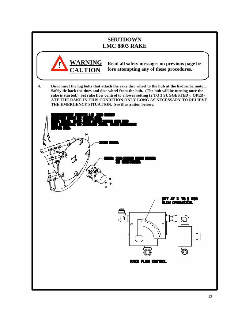
4. Disconnect the lug bolts that attach the rake disc wheel to the hub at the hydraulic motor. Safely tie back the tines and disc wheel from the hub. (The hub will be turning once the rake is started.) Set rake flow control to a lower setting (2 TO 3 SUGGESTED). OPER-ATE THE RAKE IN THIS CONDITION ONLY LONG AS NECESSARY TO RELIEVE THE EMERGENCY SITUATION. See illustration below:.
WARNING CAUTION
Read all safety messages on previous page be-fore attempting any of these procedures.
43
THE LMC BASKET RAKE
HYDRAULIC SYSTEM
TOPICS:
UNDERSTANDING THE LMC/ALLEN HYDRAULIC SYSTEM
ADJUSTING THE LMC/ALLEN RAKE HYDRAULIC SYSTEM
44
UNDERSTANDING THE LMC RAKE HYDRAULIC SYSTEM
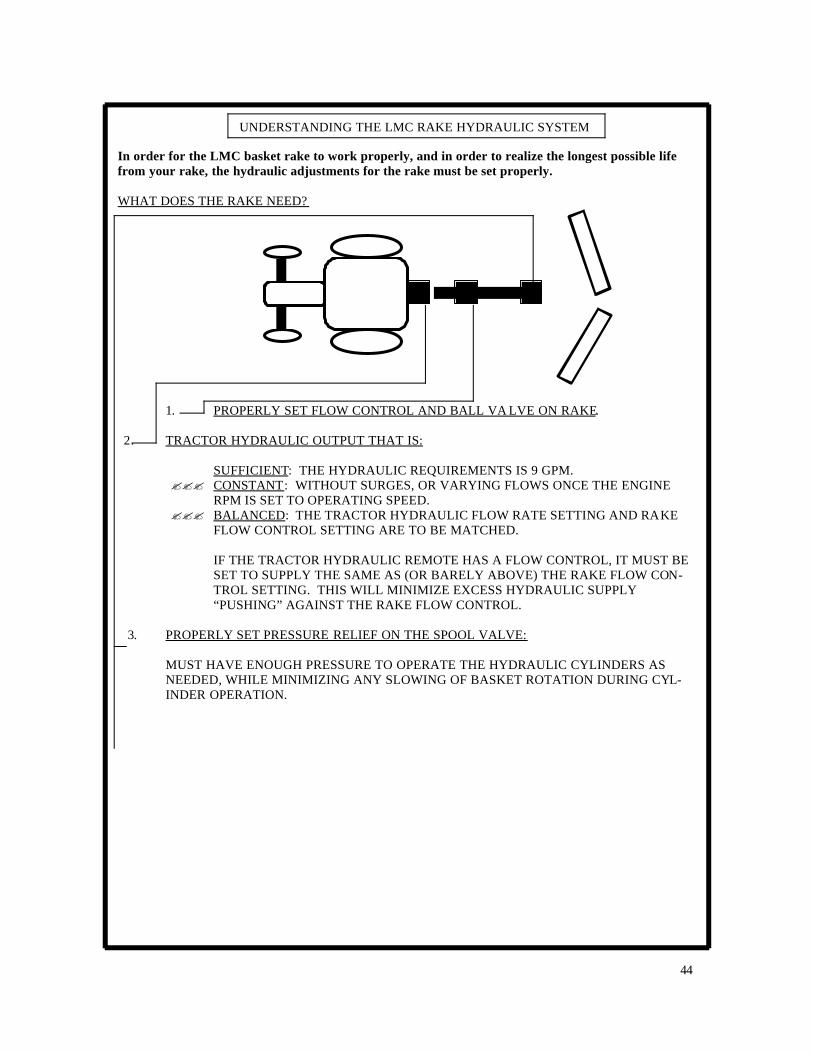
In order for the LMC basket rake to work properly, and in order to realize the longest possible life from your rake, the hydraulic adjustments for the rake must be set properly. WHAT DOES THE RAKE NEED?
1. PROPERLY SET FLOW CONTROL AND BALL VA LVE ON RAKE. 2. TRACTOR HYDRAULIC OUTPUT THAT IS:
SUFFICIENT: THE HYDRAULIC REQUIREMENTS IS 9 GPM. ??? CONSTANT: WITHOUT SURGES, OR VARYING FLOWS ONCE THE ENGINE
RPM IS SET TO OPERATING SPEED. ??? BALANCED: THE TRACTOR HYDRAULIC FLOW RATE SETTING AND RAKE
FLOW CONTROL SETTING ARE TO BE MATCHED. IF THE TRACTOR HYDRAULIC REMOTE HAS A FLOW CONTROL, IT MUST BE SET TO SUPPLY THE SAME AS (OR BARELY ABOVE) THE RAKE FLOW CON-TROL SETTING. THIS WILL MINIMIZE EXCESS HYDRAULIC SUPPLY “PUSHING” AGAINST THE RAKE FLOW CONTROL.
3. PROPERLY SET PRESSURE RELIEF ON THE SPOOL VALVE:
MUST HAVE ENOUGH PRESSURE TO OPERATE THE HYDRAULIC CYLINDERS AS NEEDED, WHILE MINIMIZING ANY SLOWING OF BASKET ROTATION DURING CYL-INDER OPERATION.

45
UNDERSTANDING THE LMC RAKE HYDRAULIC SYSTEM
1. UNDERSTANDING THE FLOW CONTROL AND BALL VALVE ON THE RAKE An understanding of these components is very important. You may indeed check their adjustments several times while getting the rake set-up to run with each different tractor.
The pressure gauge has been eliminated. Most of today's tractors have hydraulic moni-toring systems which eliminates the need for a pressure gauge. However, gauges can be provided per customer request. SIDE-LEVER adjusts the amount of flow allowed to the motors. The 0—10 digits are reference numbers for ease in repeating a cer-tain setup. The numbers DO NOT represent a certain rate (GPM, etc).
The ball valve is set open or closed depend-ing on the type of hydraulic system on the tractor. For most tractors (open-center), the ball valve is set open. Close the valve for closed center tractors. The ball valve setting will be discussed in more detail in the section “ADJUSTING THE LMC RAKE HYDRAULIC SYSTEM”.
46
UNDERSTANDING THE LMC RAKE HYDRAULIC SYSTEM
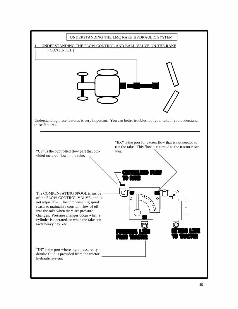
1. UNDERSTANDING THE FLOW CONTROL AND BALL VALVE ON THE RAKE (CONTINUED) Understanding these features is very important. You can better troubleshoot your rake if you understand these features.
“EX” is the port for excess flow that is not needed to run the rake. This flow is returned to the tractor reser-voir. “CF” is the controlled flow part that pro-
vided metered flow to the rake.
The COMPENSATING SPOOL is inside of the FLOW CONTROL VALVE and is not adjustable. The compensating spool reacts to maintain a constant flow of oil into the rake when there are pressure changes. Pressure changes occur when a cylinder is operated, or when the rake con-tacts heavy hay, etc.
“IN” is the port where high pressure hy-draulic fluid is provided from the tractor hydraulic system.
47
UNDERSTANDING THE LMC RAKE HYDRAULIC SYSTEM
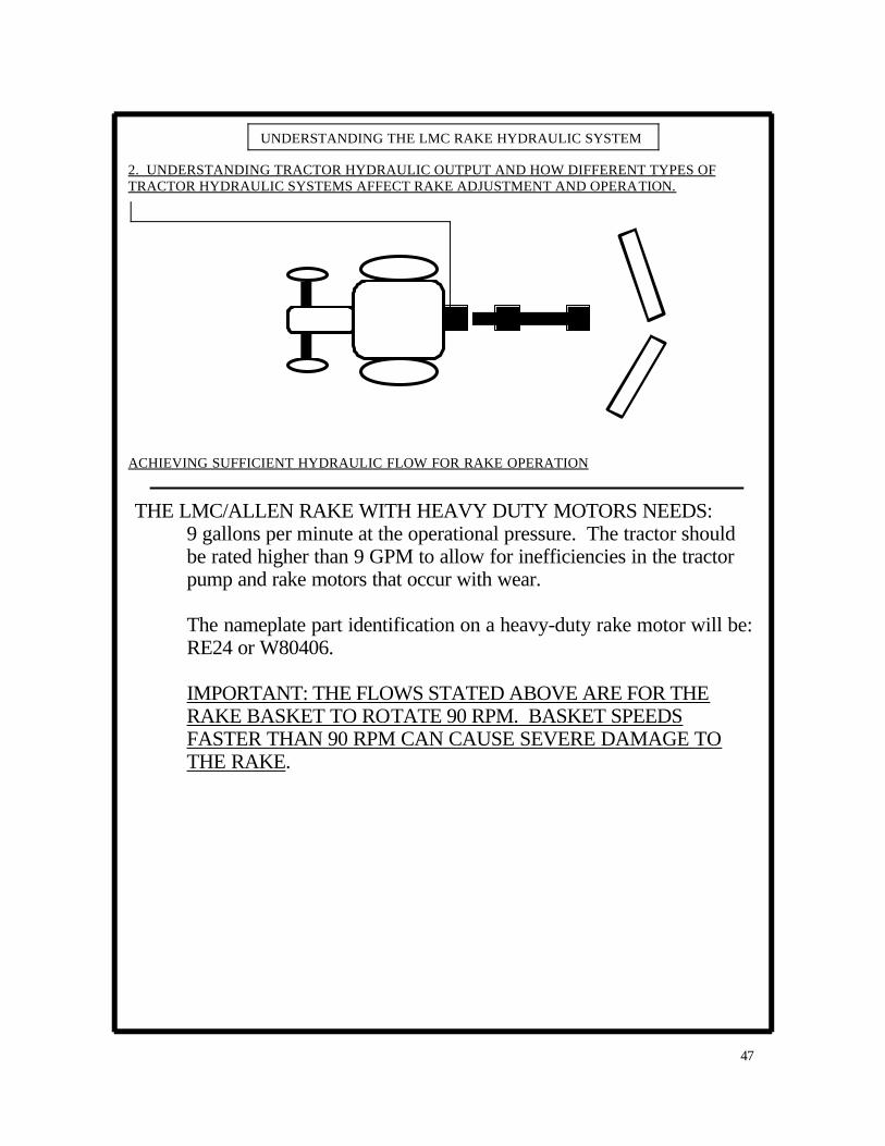
2. UNDERSTANDING TRACTOR HYDRAULIC OUTPUT AND HOW DIFFERENT TYPES OF TRACTOR HYDRAULIC SYSTEMS AFFECT RAKE ADJUSTMENT AND OPERATION. ACHIEVING SUFFICIENT HYDRAULIC FLOW FOR RAKE OPERATION
THE LMC/ALLEN RAKE WITH HEAVY DUTY MOTORS NEEDS: 9 gallons per minute at the operational pressure. The tractor should be rated higher than 9 GPM to allow for inefficiencies in the tractor pump and rake motors that occur with wear. The nameplate part identification on a heavy-duty rake motor will be: RE24 or W80406. IMPORTANT: THE FLOWS STATED ABOVE ARE FOR THE RAKE BASKET TO ROTATE 90 RPM. BASKET SPEEDS FASTER THAN 90 RPM CAN CAUSE SEVERE DAMAGE TO THE RAKE.

48
UNDERSTANDING THE LMC RAKE HYDRAULIC SYSTEM
2. UNDERSTANDING TRACTOR HYDRAULIC OUTPUT AND HOW DIFFERENT TYPES OF TRACTOR HYDRAULIC SYSTEMS AFFECT RAKE ADJUSTMENT AND OPERATION. (CONTINUED) ACHIEVING SUFFICIENT HYDRAULIC FLOW FOR RAKE OPERATION
Hydraulic flow that is “constant” means flow without surges, or other variances, once the engine rpm is set to operating speed. PERFECTLY CONSTANT FLOW IS NOT POSSIBLE. However, the hydraulic controls on the LMC rake allow for settings that minimize surging and other variances of supply flow into the rake. Surges and other variances in flow cause problems such as over speeding of the basket after a cylinder is actuated or the baskets raising “by themselves” while raking hay. ACHIEVING CONSTANT FLOW USING A TRACTOR WITH BASIC OPEN-CENTER OR BASIC CLOSED-CENTER HYDRAULIC SYSTEM. The settings are the simplest, when connecting to tractors that utilize a basic open-center, or basic closed-center hydraulic system. With these tractors, once the engine rpm is set, the hydraulic flow to the rake re-mains approximately the same. The ball valve on the rake flow control “EX” port can be set to open for open-center tractors, or closed for closed-center tractors. Starting with the rake flow control set near 0 (zero), the side lever arm of the rake flow control is rotated clockwise until the basket is counted to be ro-tating at 90 RPM. The thumbscrew of the side lever spool is then tightened finger tight to retain the adjust-ment.

49
UNDERSTANDING THE LMC RAKE HYDRAULIC SYSTEM
2. UNDERSTANDING TRACTOR HYDRAULIC OUTPUT AND HOW DIFFERENT TYPES OF TRACTOR HYDRAULIC SYSTEMS AFFECT RAKE ADJUSTMENT AND OPERATION. (CONTINUED) OBTAINING CONSTANT FLOW USING A TRACTOR WITH BUILT -IN FLOW CONTROLS and THE IMPORTANCE OF BALANCED FLOW.
Tractors with built-in flow controls pose a special problem. Which flow control is to be used to actually control the rake? Some tractors literature states that only the tractor flow control should be used, and any implement flow control should be opened to full-flow to reduce any restrictions (hence, heat build-up, etc.) in the hydraulic circuit. Whereas, this may indeed assure that the tractor is not “pushing” too much flow at the rake flow control, this method does not provide for constant flow. Here’s why: In the following scenario (figure A), the tractor flow control is providing the only flow-control restriction in the circuit. What happens if the tractor suddenly sends a surge of fluid (engine is revved higher, or pres-sure compensation “kicks in”)? Or, what happens if the tractor suddenly reduces the flow (engine RPM slowed, etc.)? The rake flow control is opened too much. Such that:
a. The basket rotation over speeds, at times. (The rake flow control provides no protection against surges from the tractor.)
b. The basket rotation slows, at times. (The rake flow control is creating no backpressure in the supply line. A slight amount of back-pressure is needed in the supply line during normal op-eration, so that if, for instance, the tractor engine rpm is reduced, then the back-pressure in the supply line may decrease, but the flow to the rake and the basket rotation speed will remain fairly constant.)
Figure A—Simplified Diagram of Flow Controls
Tractor Flow Control (Example: set at 5 GPM
Rake Flow Control (Example: set at 16 GPM

50
UNDERSTANDING THE LMC RAKE HYDRAULIC SYSTEM
2. UNDERSTANDING TRACTOR HYDRAULIC OUTPUT AND HOW DIFFERENT TYPES OF TRACTOR HYDRAULIC SYSTEMS AFFECT RAKE ADJUSTMENT AND OPERATION. (CONTINUED) OBTAINING CONSTANT FLOW USING A TRACTOR WITH BUILT -IN FLOW CONTROLS and THE IMPORTANCE OF BALA NCED FLOW. (continued)
What can happen if the tractor flow control is either fully opened or opened too much, and the rake flow control is used to control the flow? See Figure B. a. Excess heat builds up in the fluid any time that excess fluid is pushed over a relief valve,
or through a flow control valve. Hot fluid degrades more quickly, can harm the hydraulic comp o-nents, and may result in reduced basket rpm.
b. Tractors with pressure sensing or load sensing hydraulic systems may send unpredictable
surges of fluid into the rake flow control, or may try to supply a steady, very high pressure (2500+ psi). These conditions can be noted by watching the rake pressure gauge. Operational symptoms may include:
???? Tractor hydraulic system emits a “whistling” sound. ???? Rake pressure gauge reads pressures over 1000 psi with the rake stationary, the
baskets at 90 RPM, and no cylinders being operated. ???? After the control handle is released from operating a rake cylinder, the rake bas-
kets momentarily over speed, sometimes allowing the tine bars to clatter against the rake framework.
The rake baskets creep upward “by themselves” while the rake is being towed across a field.
Figure B—Simplified Diagram of Flow Controls
Tractor Flow Control (Example: set at 20 GPM
Rake Flow Control (Example: set at 5 GPM

51
UNDERSTANDING THE LMC RAKE HYDRAULIC SYSTEM
2. UNDERSTANDING TRACTOR HYDRAULIC OUTPUT AND HOW DIFFERENT TYPES OF TRACTOR HYDRAULIC SYSTEMS AFFECT RAKE ADJUSTMENT AND OPERATION. (CONTINUED) OBTAINING CONSTANT FLOW USING A TRACTOR WITH BUILT -IN FLOW CONTROLS and THE IMPORTANCE OF BALA NCED FLOW. (continued)
What is the optimum setting for the flow controls of the tractor and the rake in order to achieve the best rake life and performance? See Figure C.
Note of Caution: The following instructions should be compared with the technical instructions for your tractor. If there seems to be a difference, then call a service representative from your tractor company. The LMC/ALLEN RAKE is similar to many imple ments that have hydraulic motors requiring definitive control for which your tractor company should provide technical support.
The optimum setting of the flow control for the LMC rake is the BALANCED condition as shown in Figure C. A step-by-step method for achieving balanced flow controls is described farther on in these hydraulic instructions. The Balanced Flow Control condition utilizes the assumption that since the tractor has flow controls, it is internally equipped to properly manage excess flow capacity, rather than sending the excess flow externally to the rake flow control where heat will be added to the hydraulic fluid.
Figure C—Simplified Diagram of Flow Controls
Tractor Flow Control (Example: set barely above 5 GPM
Rake Flow Control
52
UNDERSTANDING THE LMC RAKE HYDRAULIC SYSTEM
2. UNDERSTANDING TRACTOR HYDRAULIC OUTPUT AND HOW DIFFERENT TYPES OF TRACTOR HYDRAULIC SYSTEMS AFFECT RAKE ADJUSTMENT AND OPERATION. (CONTINUED) OBTAINING CONSTANT FLOW USING A TRACTOR WITH BUILT -IN FLOW CONTROLS and THE IMPORTANCE OF BALA NCED FLOW. (continued)
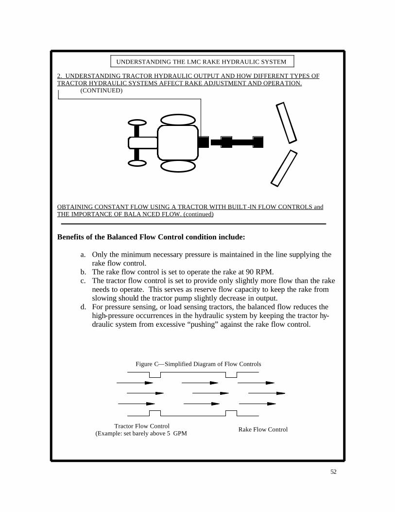
Benefits of the Balanced Flow Control condition include:
a. Only the minimum necessary pressure is maintained in the line supplying the rake flow control.
b. The rake flow control is set to operate the rake at 90 RPM. c. The tractor flow control is set to provide only slightly more flow than the rake
needs to operate. This serves as reserve flow capacity to keep the rake from slowing should the tractor pump slightly decrease in output.
d. For pressure sensing, or load sensing tractors, the balanced flow reduces the high-pressure occurrences in the hydraulic system by keeping the tractor hy-draulic system from excessive “pushing” against the rake flow control.
Figure C—Simplified Diagram of Flow Controls
Tractor Flow Control (Example: set barely above 5 GPM
Rake Flow Control
53
UNDERSTANDING THE LMC RAKE HYDRAULIC SYSTEM
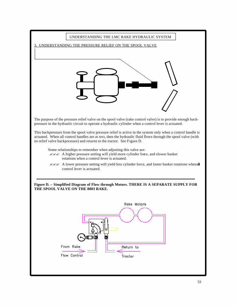
3. UNDERSTANDING THE PRESSURE RELIEF ON THE SPOOL VALVE The purpose of the pressure relief valve on the spool valve (rake control valve) is to provide enough back-pressure in the hydraulic circuit to operate a hydraulic cylinder when a control lever is actuated. This backpressure from the spool valve pressure relief is active in the system only when a control handle is actuated. When all control handles are at rest, then the hydraulic fluid flows through the spool valve (with no relief valve backpressure) and returns to the tractor. See Figure D.
Some relationships to remember when adjusting this valve are: ??? A higher pressure setting will yield more cylinder force, and slower basket
rotations when a control lever is actuated.
??? A lower pressure setting will yield less cylinder force, and faster basket rotations when a control lever is actuated.
Figure D. – Simplified Diagram of Flow through Motors. THERE IS A SEPARATE SUPPLY FOR THE SPOOL VALVE ON THE 8803 RAKE.
54
UNDERSTANDING THE LMC RAKE HYDRAULIC SYSTEM
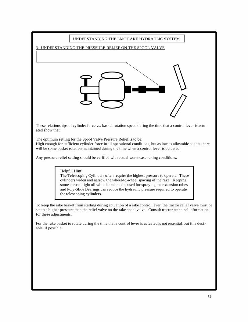
3. UNDERSTANDING THE PRESSURE RELIEF ON THE SPOOL VALVE These relationships of cylinder force vs. basket rotation speed during the time that a control lever is actu-ated show that: The optimum setting for the Spool Valve Pressure Relief is to be: High enough for sufficient cylinder force in all operational conditions, but as low as allowable so that there will be some basket rotation maintained during the time when a control lever is actuated. Any pressure relief setting should be verified with actual worst-case raking conditions.
Helpful Hint: The Telescoping Cylinders often require the highest pressure to operate. These cylinders widen and narrow the wheel-to-wheel spacing of the rake. Keeping some aerosol light oil with the rake to be used for spraying the extension tubes and Poly-Slide Bearings can reduce the hydraulic pressure required to operate the telescoping cylinders.
To keep the rake basket from stalling during actuation of a rake control lever, the tractor relief valve must be set to a higher pressure than the relief valve on the rake spool valve. Consult tractor technical information for these adjustments. For the rake basket to rotate during the time that a control lever is actuated is not essential, but it is desir-able, if possible.

55
NOTES
56
ADJUSTING THE LMC/ALLEN RAKE HYDRAULIC SYSTEM
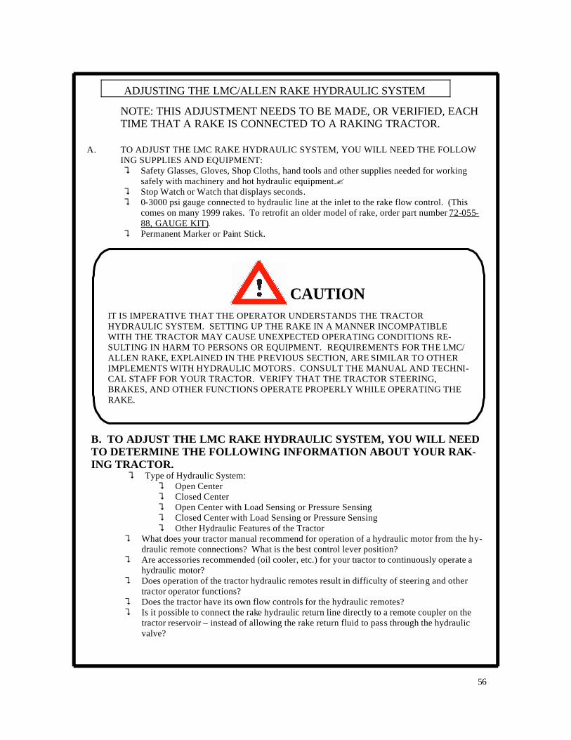
NOTE: THIS ADJUSTMENT NEEDS TO BE MADE, OR VERIFIED, EACH TIME THAT A RAKE IS CONNECTED TO A RAKING TRACTOR.
A. TO ADJUST THE LMC RAKE HYDRAULIC SYSTEM, YOU WILL NEED THE FOLLOW ING SUPPLIES AND EQUIPMENT:
? Safety Glasses, Gloves, Shop Cloths, hand tools and other supplies needed for working safely with machinery and hot hydraulic equipment.?
? Stop Watch or Watch that displays seconds. ? 0-3000 psi gauge connected to hydraulic line at the inlet to the rake flow control. (This
comes on many 1999 rakes. To retrofit an older model of rake, order part number 72-055-88, GAUGE KIT).
? Permanent Marker or Paint Stick.
CAUTION IT IS IMPERATIVE THAT THE OPERATOR UNDERSTANDS THE TRACTOR HYDRAULIC SYSTEM. SETTING UP THE RAKE IN A MANNER INCOMPATIBLE WITH THE TRACTOR MAY CAUSE UNEXPECTED OPERATING CONDITIONS RE-SULTING IN HARM TO PERSONS OR EQUIPMENT. REQUIREMENTS FOR THE LMC/ALLEN RAKE, EXPLAINED IN THE PREVIOUS SECTION, ARE SIMILAR TO OTHER IMPLEMENTS WITH HYDRAULIC MOTORS. CONSULT THE MANUAL AND TECHNI-CAL STAFF FOR YOUR TRACTOR. VERIFY THAT THE TRACTOR STEERING, BRAKES, AND OTHER FUNCTIONS OPERATE PROPERLY WHILE OPERATING THE RAKE.
B. TO ADJUST THE LMC RAKE HYDRAULIC SYSTEM, YOU WILL NEED TO DETERMINE THE FOLLOWING INFORMATION ABOUT YOUR RAK-ING TRACTOR.
? Type of Hydraulic System: ? Open Center ? Closed Center ? Open Center with Load Sensing or Pressure Sensing ? Closed Center with Load Sensing or Pressure Sensing ? Other Hydraulic Features of the Tractor
? What does your tractor manual recommend for operation of a hydraulic motor from the hy-draulic remote connections? What is the best control lever position?
? Are accessories recommended (oil cooler, etc.) for your tractor to continuously operate a hydraulic motor?
? Does operation of the tractor hydraulic remotes result in difficulty of steering and other tractor operator functions?
? Does the tractor have its own flow controls for the hydraulic remotes? ? Is it possible to connect the rake hydraulic return line directly to a remote coupler on the
tractor reservoir – instead of allowing the rake return fluid to pass through the hydraulic valve?
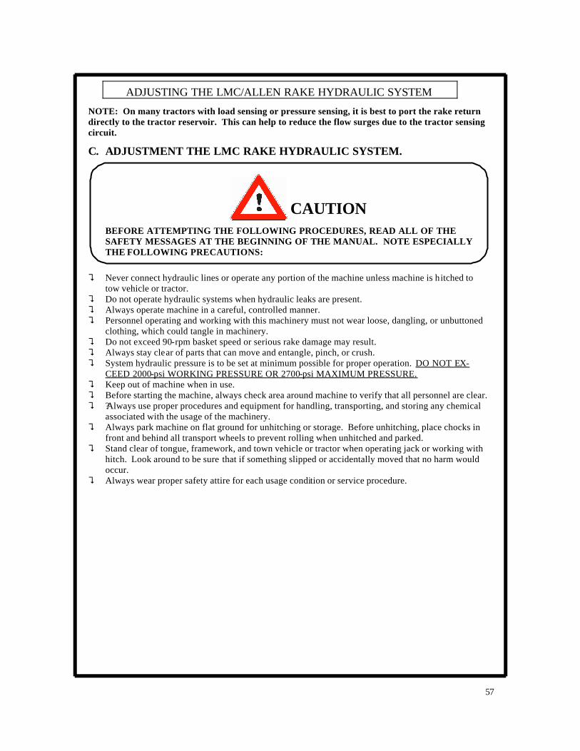
C. ADJUSTMENT THE LMC RAKE HYDRAULIC SYSTEM.
? Never connect hydraulic lines or operate any portion of the machine unless machine is hitched to tow vehicle or tractor.
? Do not operate hydraulic systems when hydraulic leaks are present. ? Always operate machine in a careful, controlled manner. ? Personnel operating and working with this machinery must not wear loose, dangling, or unbuttoned
clothing, which could tangle in machinery. ? Do not exceed 90-rpm basket speed or serious rake damage may result. ? Always stay clear of parts that can move and entangle, pinch, or crush. ? System hydraulic pressure is to be set at minimum possible for proper operation. DO NOT EX-
CEED 2000-psi WORKING PRESSURE OR 2700-psi MAXIMUM PRESSURE. ? Keep out of machine when in use. ? Before starting the machine, always check area around machine to verify that all personnel are clear. ? ?Always use proper procedures and equipment for handling, transporting, and storing any chemical
associated with the usage of the machinery. ? Always park machine on flat ground for unhitching or storage. Before unhitching, place chocks in
front and behind all transport wheels to prevent rolling when unhitched and parked. ? Stand clear of tongue, framework, and town vehicle or tractor when operating jack or working with
hitch. Look around to be sure that if something slipped or accidentally moved that no harm would occur.
? Always wear proper safety attire for each usage condition or service procedure.
CAUTION BEFORE ATTEMPTING THE FOLLOWING PROCEDURES, READ ALL OF THE SAFETY MESSAGES AT THE BEGINNING OF THE MANUAL. NOTE ESPECIALLY THE FOLLOWING PRECAUTIONS:
57
ADJUSTING THE LMC/ALLEN RAKE HYDRAULIC SYSTEM
NOTE: On many tractors with load sensing or pressure sensing, it is best to port the rake return directly to the tractor reservoir. This can help to reduce the flow surges due to the tractor sensing circuit.

C. ADJUSTMENT THE LMC RAKE HYDRAULIC SYSTEM. (continued)
1. Make sure that the rake hydraulic lines ARE NOT connected to the tractor. 2. As per the safety messages, hitch the rake to the tractor and connect the hydraulic lines. 3. Before turning on the tractor hydraulics, first set the rake flow control side lever to 2-1/2. 4. Set the ball valve to open or closed, as required for the type of tractor hydraulic system.
See figure, below: Rake Flow Control
CAUTION BEFORE ATTEMPTING THE FOLLOWING PROCEDURES, READ ALL OF THE SAFETY MESSAGES AT THE BEGINNING OF THE MANUAL. NOTE ESPECIALLY THE FOLLOWING PRECAUTIONS:
58
ADJUSTING THE LMC/ALLEN RAKE HYDRAULIC SYSTEM
WARNING: AVOID HIGH-PRESSURE FLUIDS
1. Escaping fluid under pressure can penetrate the skin causing serious injury. 2. Shut off tractor before connecting or disconnecting hydraulic lines at tractor. 3. Relieve pressure before unhooking hydraulic or other lines. Tighten all connections be-
fore applying pressure. Keep hand and body away from pinholes and components that may eject fluids under pressure. Use a piece of cardboard to search for leaks.
4. If ANY fluid is injected into the skin, a doctor familiar with this type of injury must surgi-cally remove it within a few hours.
C. ADJUSTMENT THE LMC RAKE HYDRAULIC SYSTEM. (continued)
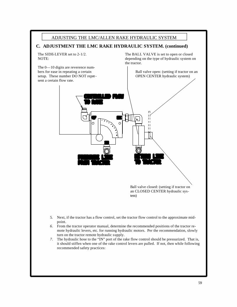
5. Next, if the tractor has a flow control, set the tractor flow control to the approximate mid-point.
6. From the tractor operator manual, determine the recommended positions of the tractor re-mote hydraulic levers, etc. for running hydraulic motors. Per the recommendation, slowly turn on the tractor remote hydraulic supply.
7. The hydraulic hose to the “IN” port of the rake flow control should be pressurized. That is, it should stiffen when one of the rake control levers are pulled. If not, then while following recommended safety practices:
59
ADJUSTING THE LMC/ALLEN RAKE HYDRAULIC SYSTEM
The SIDE-LEVER set to 2-1/2. NOTE: The 0—10 digits are reverence num-bers for ease in repeating a certain setup. These number DO NOT repre-sent a certain flow rate.
The BALL VALVE is set to open or closed depending on the type of hydraulic system on the tractor.
Ball valve open: (setting if tractor on an OPEN CENTER hydraulic system)
Ball valve closed: (setting if tractor on an CLOSED CENTER hydraulic sys-tem)
C. ADJUSTMENT THE LMC RAKE HYDRAULIC SYSTEM. (continued)
? Using rake control levers, relieve pressure in the rake hydraulic system. ? Shut off the tractor remote hydraulic supply. ? Shut off the tractor engine. ? With the tractor engine shut-off, again use tractor and rake control levers, to try and relieve
any pressure in the rake hydraulic system. ? Now connect the hoses correctly to the tractor.
Repeat all phases of this step until proper hose connection is accomplished: 8. At this point, the rake should be properly connected to the tractor and the baskets should be turning
very slowly. To set the baskets to the proper speed of 85 to 90 RPM, do the following:
NOTE: If the tractor DOES NOT have flow controls, then the flow adjustment for the rake is now com-plete. Proceed to the instructions for “Adjustment of the Pressure Relief on the Rake Spool Valve.” If the tractor DOES have f low controls, continue with the following instructions.
60
ADJUSTING THE LMC/ALLEN RAKE HYDRAULIC SYSTEM
CAUTION BEFORE ATTEMPTING THE FOLLOWING PROCEDURES, READ ALL OF THE SAFETY MESSAGES AT THE BEGINNING OF THE MANUAL. NOTE ESPECIALLY THE FOLLOWING PRECAUTIONS:
BEFORE ATTEMPTING THE FOLLOWING PROCEDURES, READ ALL OF THE SAFETY MESSAGES IN THIS MANUAL. NOTE ESPECIALLY:
1. With a watch, time the rotations of the mark on the Disc Wheel. 90 RPM = 90
revolutions in 60 seconds, or 45 revolutions in 30 seconds. 2. At the rake flow control, slowly move the side-lever one or two digits to a higher
setting. Count the rake basket RPM. 3. Repeat this step until 85-90 basket RPM is achieved.
CAUTION

C. ADJUSTMENT THE LMC RAKE HYDRAULIC SYSTEM. (continued)
61
ADJUSTING THE LMC/ALLEN RAKE HYDRAULIC SYSTEM
RAKE PRESSURE GAUGE
RAKE FLOW CONTROL
EXAMPLE: The pressure jumps up 100 psi to register 600 psi on the gauge at the instant the ball valve is closed while testing for the balanced flow condition.
500 psi is a typical operational pressure when oil is warmed, no cylinders are in operation, and only the baskets are running at 90 RPM.
Example of Pressure Jump Noted When Checking for Balanced Flow
Note that it is preferable to have the lowest “jump” possible in pressure (0-100 psi) that will allow proper rake operation. This helps assure that the rake flow control is bypassing and heating the minimum possible amount of fluid. To re-duce the “jump” in pressure, keep the rake flow control setting as-is, and reduce the tractor flow control setting.

C. ADJUSTMENT THE LMC RAKE HYDRAULIC SYSTEM. (continued)
62
ADJUSTING THE LMC/ALLEN RAKE HYDRAULIC SYSTEM
If the rake will not turn 85-90 RPM with the rake flow control at the highest setting, then: ? Set the rake flow control side lever to 2- ½, and then increase the tractor flow control 1 turn ? Slowly increase the setting of the rake flow control side lever until 85-90 RPM is achieved.
If the rake baskets are rotating faster than 90 RPM then decrease the setting of the rake flow control side lever until 85-90 rpm is achieved.
BALANCING THE TRACTOR FLOW CONTROL AND THE RAKE FLOW CONTROL To verify that the tractor is trying to supply only slightly more fluid than the rake needs, perform the fol-lowing steps:?
? With the tractor engine at field operational speed (usually 2000-2300 RPM), and the rake bas-ket rotation at 85-90 RPM, repeatedly move the rake ball valve handle back and forth to the open and closed positions while watching the pressure gauge on the rake.
? Note that at the same instant that the ball valve is closed, the pressure gauge should have a momentary “jump” of not more than 0-200 psi above the operational pressure. See the fo l-lowing example.
NOTE: At this point, if the raking tractor hydraulic system DOES NOT have load sensing or pressure sensing then move directly to the instruction for “ADJUSTMENT OF THE SPOOL VALVE PRESSURE RELIEF.” If the raking tractor hydraulic system, DOES have load sensing or pressure sensing continue on in the following instructions.
Ball Valve Open (Setting if tractor has OPEN CENTER hydraulic system
Ball Valve Closed (Setting if tractor has CLOSED CENTER hydraulic system

C. ADJUSTMENT THE LMC RAKE HYDRAULIC SYSTEM. (continued)
63
ADJUSTING THE LMC/ALLEN RAKE HYDRAULIC SYSTEM
If you have not done so already, you should read the section of this manual “UNDERSTANDING THE LMC/ALLEN RAKE HYDRAULIC SYSTEM”. Reading that section will help provide understanding of the cause and effect relationship of the following rake symptoms.
Symptoms of Tractor Flow Control not Balanced with Rake Flow Control:
Symptom: Basket rises by itself while raking hay.
Symptom: After raising the baskets, or operating other cylinders: at the instant that the control lever is released, the baskets over-speed and may even clatter against the frame of the rake.
Symptom: After raising the baskets, or operating other cylinders: after the control lever is released, pressure remains above 1000-2000 psi and does not return to the normal raking pressure of 500-700 psi.
Symptom: Pressure on the rake pressure gauge is continuously above 1000 psi when only the bas-kets are operating (no cylinders operating). Ideally, after the oil is at operating temperature, the pressure gauge should read 500-700 psi when only the baskets are operating. Possible Remedies for Above Symptoms: Read through the section of this manual “UNDERSTANDING THE LMC/ALLEN RAKE HYDRAULIC SYSTEM”. Then, review the type of system that you are using. Proceed again through these adjustments instructions and verify that the proper rake and tractor settings are used. Give special attention to the instructions for “Balancing the Tractor Flow Control and the Rake Flow Control”.

C. ADJUSTMENT THE LMC RAKE HYDRAULIC SYSTEM. (continued)
64
ADJUSTING THE LMC/ALLEN RAKE HYDRAULIC SYSTEM
If the above remedies do not help, then inquire with your tractor manufacturer’s hydraulic staff about the feasibility of connecting the rake return line directly to the tractor reservoir port, instead of having the rake return line connected to a port on a tractor hydraulic remote valve.
Tractor hydraulic systems have evolved much over time, and continue to have new developments. If the tractor cannot seem to be adjusted to operate the rake properly, then use the following rake information to describe the requirements to your tractor manufacturer’s hydraulic technical staff if seeking their assis-tance.
LMC/ALLEN RAKE HYDRAULIC SYSTEM: Operating Flow Rate: 9 gpm for heavy-duty motors Flow capacity of Rake Flow Control Valve: 16 gpm
Note: 16 gpm includes the “CF” (controlled flow or operational flow rate) plus the “EX” flow (excess flow not needed and therefore returned to tank).
Pressure requirements for baskets idling at 85-90 rpm (no hay being raked), oil at operating tem-perature, and no cylinders being operated: 500-700 psi, typical Pressure requirements for operation of a cylinder: 1500-2000 psi, typical. The pressure relief on the spool valve used to operate the cylinders sets this pressure.
Maximum tractor hydraulic remote supply pressure = 2500 psi. This is determined by the remote hydraulic system setting of the tractor. Refer to the tractor manual for adjustment instructions.
CAUTION Certain tractors supply remote hydraulic fluid at pressures above 2500 psi. Although there is a safety factor associated with hydraulic ratings, NEVER ALLOW THE LMC/ALLEN RAKE TO BE RUN ON A TRACTOR THAT SUPPLIES REMOTE HYDRAULIC FLUID AT PRESSURE OVER 2700 PSI.

C. ADJUSTMENT THE LMC RAKE HYDRAULIC SYSTEM. (continued)
65
ADJUSTING THE LMC/ALLEN RAKE HYDRAULIC SYSTEM
Rake Hydraulic Circuit, Basic Description:
Hydraulic fluid leaves the tractor, passes through a pressure compensated flow control valve, then passes through the first hydraulic motor, then the second hydraulic motor. The hydraulic oil then passes through an open-centered spool valve used to occasionally operate the cylinders, and then the oil passes from this valve to the tractor.
Open center tractor hydraulics and the rake ball valve:
When oil is in the pressure compensated flow control valve the extra flow not needed for the rake does not pass through the “EX” port since the rake ball valve is closed. The tractor is supposed to automati-cally adjust its pump output to the lower flow requirement. Closed center tractor hydraulics and the rake ball valve: When oil is in the pressure compensated flow control valve the extra flow not needed for the rake does not pass through the “EX” port since the rake ball valve is closed. The tractor is supposed to automati-cally adjust its pump output to the lower flow requirement. The pressure relief valve on the spool valve provides pressure when a lever is pulled in order to oper-ate the cylinders. The check valve allows the rake motors to free wheel and slow down gently when the hydraulic flow is ceased.
Note About Hydraulic Quick Connectors:
Quick Connectors on hydraulic supply hoses: As with any coupler, there may be some restriction in the lines because of theses couplers. Quick couplers usually present no problem for rake requirements, but may cause erratic responses in tractors having high capacity pumps with load sensing or pressure sensing hydraulic systems.

D. ADJUSTMENT OF THE PRESSURE RELIEF AT THE SPOOL VALVE
66
ADJUSTING THE LMC/ALLEN RAKE HYDRAULIC SYSTEM
CAUTION BEFORE ATTEMPTING THE FOLLOWING PROCEDURES, READ ALL OF THE SAFETY MESSAGES AT THE BEGINNING OF THE MANUAL. NOTE ESPECIALLY THE FOLLOWING PRECAUTIONS:
? Never connect hydraulic lines or operate any portion of the machine unless machine is hitched to tow vehicle or tractor.
? Do not operate hydraulic systems when hydraulic leaks are present. ? Always operate machine in a careful, controlled manner. ? Personnel operating and working with this machinery must not wear loose, dangling, or un-
buttoned clothing that could tangle in machinery. ? Always stay clear of parts that can move and entangle, pinch, or crush. ? System hydraulic pressure is to be set at minimum possible for proper operation. DO NOT
EXCEED 2000-psi WORKING PRESSURE OR 2700-psi MAXIMUM PRESSURE. ? Before starting the machine, always check area around machine to verify that all personnel
are clear. ? Always use proper procedures and equipment for handling, transporting, and storing any
chemical associated with the usage of the machinery. ? Always park machine on flat ground for unhitching or storage. Before unhitching, place
chocks in front and behind all transport wheels to prevent rolling when unhitched and parked.
? Stand clear of tongue, framework, and towing vehicle or tractor when operating jack or working with hitch. Look around to be sure that if something slipped or accidentally moved that no harm would occur.
? Always wear proper safety attire for each usage condition or service procedure. ? Keep out of machine when in use.
To set the pressure relief at the spool valve follow these steps: 1. Hitch the LMC/ALLEN rake to the tractor. 2. Connect the hydraulic hoses to the tractor, and set the hydraulic adjustments as per the in-
structions in “C. Adjustment of the LMC/ALLEN Hydraulic System”. 3. If the tractor has its own flow controls, make sure that the tractor flow control and the rake
flow control are balanced, as per the instructions in “C. Adjustment of the LMC/ALLEN Hy-draulic System”.

D. ADJUSTMENT OF THE PRESSURE RELIEF AT THE SPOOL VALVE
67
ADJUSTING THE LMC/ALLEN RAKE HYDRAULIC SYSTEM
4. Start the tractor. While driving forward, using the rake control, extend both Extension Arms to allow maximum width between the rake wheels. Next fully pivot both baskets to allow the maximum space between then. See Figure: Position of Rake Baskets Prior to Servicing Spool Valve.
5. Using the rake controls, raise the baskets fully. After the baskets have fully risen, continue to hold the
rake control in the “Basket Raise” position and at the same time read the pressure from the rake pres-sure gauge. The pressure reading indicates the setting of the spool valve pressure relief. The gauge should read a steady pressure between 1500 to 2000 psi. If the pressure is above 2000 psi, the follo w-ing conditions may exist:
A) The tractor flow control is opened too much and has not been brought into balance with the
rake flow control. The tractor has likely already been trying to “push” too much fluid through the rake flow control. The tractor is trying to “push” as much flow into the system as needed to achieve the maximum tractor pressure. (This maximum tractor pressure is the high pressure at which the tractor normally would release a control lever from detent after a remote cylinder has fully extended.) Suggested Remedy: Follow the instructions for “Balancing the Tractor Flow Control and the Rake Flow Control”, as seen previously in these instructions.
B) The ball valve on the rake flow control is improperly set for the type of tractor hydraulic sys-tem that is being used. Suggested Remedy: Follow the instructions for adjusting the rake flow control valve. Note especially the sections regarding the setting of the rake ball valve.
C) The tractor has a large capacity pump such that the 5 or 9 gallon per minute requirement for proper rake operation is a “low” flow for the tractor. The tractor load sensing or pressure sensing function responds erratically at the “low” flow of 5 to 9 gallons per minute. Sug-gested Remedy: Consult with your tractor manufacturer hydraulic staff to determine a mean of connecting the rake or setting the tractor that will allow proper rake operation.
D) The pressure relief of the spool valve needs to be set. Remedy: Proceed through the remain-der of these instructions:
Extend the Extension Arms, and orient the baskets, as shown, for maximum width possible.
RAKE SPOOL VALVE
Tractor flow control
Rake flow control

D. ADJUSTMENT OF THE PRESSURE RELIEF AT THE SPOOL VALVE
68
ADJUSTING THE LMC/ALLEN RAKE HYDRAULIC SYSTEM
?? To adjust the setting of the pressure relief valve at the spool valve, the following objectives must be kept in mind.?? System back pressure due to the pressure relief valve must not exceed 2000 psi. Typical set-
tings range from 1500 to 2000 psi. ? Enough back pressure to operate all of the cylinders. The extension cylinders are usually the
most difficult and should be used to verify proper adjustment. ? No more back pressure than is necessary, since a higher backpressure reduces the basket
speed during cylinder operation. Helpful Hint: Keeping aerosol lubricant (drying type) handy to apply on the extension tubes and poly wear pads can reduce the hydraulic pressure setting required to extend and retract the extension arms.
NOTICE Tractor must be towing rake while the extension arms are being extended or retracted. Rake MUST NOT be sitting still or else damage to the tires or rake is likely to occur. Never operate a rake with the extension arms fully extended. If an extension arm fully extends, you should retract it about 4 inches prior to towing the rake any farther. This assists the ability of the rake to withstand unexpected shock loads, rough terrain, etc.
Repeat the following sequence until an acceptable setting is accomplished. ? Read the system pressure as per the method in Step 5, above. ? Using the rake operator control, lower the baskets and relieve any other hydraulic pressure
in the rake. ? Shut off the tractor. ? Go to the relief valve, loosen the locking nut, and rotate 1 turn. ? Usually, clockwise = increase pressure setting counter clockwise = decrease pressure setting. ? Re-tighten the locknut. ? Start the tractor. Read the system pressure as per Step 5.

69
MAINTENANCE
LMC 8803 RAKE
70
MAINTENANCE LMC BASKET RAKE
WARNING: AVOID HIGH-PRESSURE FLUIDS
1. Escaping fluid under pressure can penetrate the skin causing serious injury. 2. Shut off tractor before connecting or disconnecting hydraulic lines at tractor. 3. Relieve pressure before unhooking hydraulic or other lines. Tighten all connections be-
fore applying pressure. Keep hand and body away from pinholes and components that may eject fluids under pressure. Use a piece of cardboard to search for leaks.
4. If ANY fluid is injected into the skin, a doctor familiar with this type of injury must surgi-cally remove it within a few hours.
Read all SAFETY MESSAGES at the beginning of this manual before attempting any of the procedures described in this section.
Regard especially the following: BEFORE APPROACHING OR ENTERING ANY MECHANISM TO SERVICE, INSPECT, OR MAKE ADJUSTMENTS:
A. LOWER UNIT TO THE GROUND. B. SHUT THE TRACTOR OFF. C. LOCK THE TRACTOR’S PARKING BRAKE. D. REMOVE THE KEY.
STAND CLEAR
Look around to be sure that if something slipped or accidentally moved that no harm would occur. Personnel operating and working with machinery must not wear loose, dangling or unbuttoned clothing that could tangle in machinery.
CAUTION

71
LMC BASKET RAKE
WARNING CAUTION
Read all safety messages on previous page be-fore attempting any of these procedures.
Stripper Bar Alignment Keep the stripper bar ribs aligned to prevent contact with the tines at any point as the basket revolves. There should be a minimum of ½” clearance at all times. See Fig. 19. 1) To align ribs for clearance, use either a hickey or pipe wrench as illustrated to re-position the stripper
bar.
“HICKEY BAR”
Fig. 19
HYDRAULIC ORBITAL MOTOR REMOVAL
To replace the orbital motor follow this proce-dure 1) Support the basket by wrapping a chain
around the tine bar and securing it to the frame, see Fig. 20, Item 1.
2) Remove the four motor mounting bolts see, Fig. 20, Item 2.
3) Remove the center motor shaft bolt, see Fig. 20, Item 3.
4) With a port-a-press, press the motor shaft out of the hub.
5) To install the orbital motor, reverse the process.
Fig. 20

72
MAINTENANCE LMC BASKET RAKE
WARNING: AVOID HIGH-PRESSURE FLUIDS
1. Escaping fluid under pressure can penetrate the skin causing serious injury. 2. Shut off tractor before connecting or disconnecting hydraulic lines at tractor. 3. Relieve pressure before unhooking hydraulic or other lines. Tighten all connections be-
fore applying pressure. Keep hand and body away from pinholes and components that may eject fluids under pressure. Use a piece of cardboard to search for leaks.
4. If ANY fluid is injected into the skin, a doctor familiar with this type of injury must surgi-cally remove it within a few hours.
Read all SAFETY MESSAGES at the beginning of this manual before attempting any of the procedures described in this section.
Regard especially the following: BEFORE APPROACHING OR ENTERING ANY MECHANISM TO SERVICE, INSPECT, OR MAKE ADJUSTMENTS:
A. LOWER UNIT TO THE GROUND. B. SHUT THE TRACTOR OFF. C. LOCK THE TRACTOR’S PARKING BRAKE. D. REMOVE THE KEY.
STAND CLEAR
Look around to be sure that if something slipped or accidentally moved that no harm would occur. Personnel operating and working with machinery must not wear loose, dangling or unbuttoned clothing that could tangle in machinery.
CAUTION
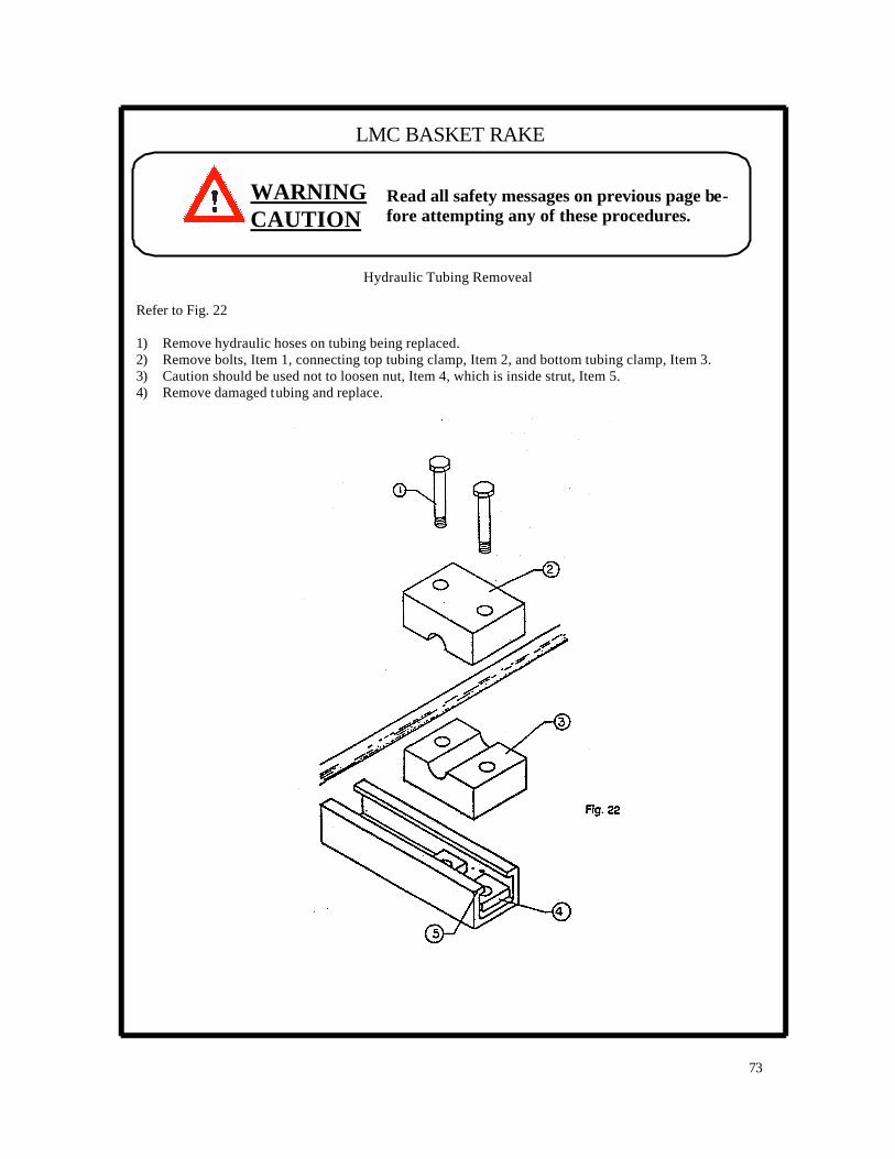
73
LMC BASKET RAKE
WARNING CAUTION
Read all safety messages on previous page be-fore attempting any of these procedures.
Hydraulic Tubing Removeal
Refer to Fig. 22 1) Remove hydraulic hoses on tubing being replaced. 2) Remove bolts, Item 1, connecting top tubing clamp, Item 2, and bottom tubing clamp, Item 3. 3) Caution should be used not to loosen nut, Item 4, which is inside strut, Item 5. 4) Remove damaged tubing and replace.

74
MAINTENANCE LMC BASKET RAKE
WARNING: AVOID HIGH-PRESSURE FLUIDS
1. Escaping fluid under pressure can penetrate the skin causing serious injury. 2. Shut off tractor before connecting or disconnecting hydraulic lines at tractor. 3. Relieve pressure before unhooking hydraulic or other lines. Tighten all connections be-
fore applying pressure. Keep hand and body away from pinholes and components that may eject fluids under pressure. Use a piece of cardboard to search for leaks.
4. If ANY fluid is injected into the skin, a doctor familiar with this type of injury must surgi-cally remove it within a few hours.
Read all SAFETY MESSAGES at the beginning of this manual before attempting any of the procedures described in this section.
Regard especially the following: BEFORE APPROACHING OR ENTERING ANY MECHANISM TO SERVICE, INSPECT, OR MAKE ADJUSTMENTS:
A. LOWER UNIT TO THE GROUND. B. SHUT THE TRACTOR OFF. C. LOCK THE TRACTOR’S PARKING BRAKE. D. REMOVE THE KEY.
STAND CLEAR
Look around to be sure that if something slipped or accidentally moved that no harm would occur. Personnel operating and working with machinery must not wear loose, dangling or unbuttoned clothing that could tangle in machinery.
CAUTION

75
LMC BASKET RAKE
WARNING CAUTION
Read all safety messages on previous page be-fore attempting any of these procedures.
Removal of Lift Cylinder There are times when the removal of the lift cylinder or adjustment or components are necessary. The following procedure should be followed. See Fig. 24.
1) Place below the basket frame, Item 1, a jack stand or other suitable blocking means. 2) Lower the basket by turning the adjustment handle, Item 2, until the basket frame is resting
on the jack stand and all tension has been removed from the lift cylinders. 3) Remove hydraulics hose, (not shown), from lift cylinder. 4) Remove cotter key on cylinder pin and then remove the pin. The cylinder is now free on the
bottom. 5) Remove cylinder pin from cylinder rod on top and bottom. 6) Cylinder should now be free and replacement of the parts made. 7) Reverse process for installation.
ADJUSTMENT HANDLE, ITEM #2
ADJUSTMENT HANDLE, ITEM #2 Fig. 24

76
MAINTENANCE LMC BASKET RAKE
WARNING: AVOID HIGH-PRESSURE FLUIDS
1. Escaping fluid under pressure can penetrate the skin causing serious injury. 2. Shut off tractor before connecting or disconnecting hydraulic lines at tractor. 3. Relieve pressure before unhooking hydraulic or other lines. Tighten all connections be-
fore applying pressure. Keep hand and body away from pinholes and components that may eject fluids under pressure. Use a piece of cardboard to search for leaks.
4. If ANY fluid is injected into the skin, a doctor familiar with this type of injury must surgi-cally remove it within a few hours.
Read all SAFETY MESSAGES at the beginning of this manual before attempting any of the procedures described in this section.
Regard especially the following: BEFORE APPROACHING OR ENTERING ANY MECHANISM TO SERVICE, INSPECT, OR MAKE ADJUSTMENTS:
A. LOWER UNIT TO THE GROUND. B. SHUT THE TRACTOR OFF. C. LOCK THE TRACTOR’S PARKING BRAKE. D. REMOVE THE KEY.
STAND CLEAR
Look around to be sure that if something slipped or accidentally moved that no harm would occur. Personnel operating and working with machinery must not wear loose, dangling or unbuttoned clothing that could tangle in machinery.
CAUTION

Removal and Installation of Tines The rakes tines are mounted individually so that they can be replaced easily without removing the tine bar or discarding a pair of teeth, see. Fig 25.
1) Shorten the replacement tine to the length of the other tines on the bar. 2) Remove 3/8” x 2 ½” bolt, Item 1, that connects the tine, Item 2, to the tine bar, Item 3. 3) Attach new tine to tine bar. Caution should be used to make sure new tines are replaced in the
same sequence and pattern as the other tines. 4) When installing any rubber-mounted tine, pull tines into saddle before tightening the mounting
belt. 5) The tines should be checked and straightened periodically to keep them from contacting the
stripper bars and contributing to failures. 6) Tighten the tine mounting bolts to 20 ft. lb. of torque. 7) Follow same procedure for installation of optional multi tines.
Tine Bar Replacement The tine bar has been designed to make changing or replacing it very easy. Refer to Fig. 25.
1) Remove tines, Item 2, from tine bar, Item 3. 2) Remove 3/4” x 4” long bearing bolt, Item 4 that fastens the tine bar to the disc Item 5. 3) Remove tine bar from the disc. 4) Reverse the process to install.
Bearing Replacement 1) Remove Item 7 & 6 from Item 4. 2) Remove Item 9 & 10 from Item 11. ( Typical in three locations per bearing.) 3) Remove bad bearing and position new bearing. 4) Place Item 11 in place and position Item 9 and 10 back in place. 5) Position Item 4 through bearing. 6) Place tine bar back against bearing and add Item 6 and 7. 7) Securely tighten Item 7 on Item 4.
77
LMC BASKET RAKE
WARNING CAUTION
Read all safety messages on previous page be-fore attempting any of these procedures.

78
MAINTENANCE LMC BASKET RAKE
WARNING: AVOID HIGH-PRESSURE FLUIDS
1. Escaping fluid under pressure can penetrate the skin causing serious injury. 2. Shut off tractor before connecting or disconnecting hydraulic lines at tractor. 3. Relieve pressure before unhooking hydraulic or other lines. Tighten all connections be-
fore applying pressure. Keep hand and body away from pinholes and components that may eject fluids under pressure. Use a piece of cardboard to search for leaks.
4. If ANY fluid is injected into the skin, a doctor familiar with this type of injury must surgi-cally remove it within a few hours.
Read all SAFETY MESSAGES at the beginning of this manual before attempting any of the procedures described in this section.
Regard especially the following: BEFORE APPROACHING OR ENTERING ANY MECHANISM TO SERVICE, INSPECT, OR MAKE ADJUSTMENTS:
A. LOWER UNIT TO THE GROUND. B. SHUT THE TRACTOR OFF. C. LOCK THE TRACTOR’S PARKING BRAKE. D. REMOVE THE KEY.
STAND CLEAR
Look around to be sure that if something slipped or accidentally moved that no harm would occur. Personnel operating and working with machinery must not wear loose, dangling or unbuttoned clothing that could tangle in machinery.
CAUTION

79
LMC BASKET RAKE
WARNING CAUTION
Read all safety messages on previous page be-fore attempting any of these procedures.
Swing Arm Bushing Replacement Remove basket from swing arm. Remove swing cylinder or top link and mounting bracket. (This depends on which model you have.) Raise main frame #3 off of lower half #2. Inspect guides in #3 (Replace if needed.) Replace bronze bushings in swing arm #1. Reverse above for installation. See Fig. 26
Fig. 26

80
MAINTENANCE LMC BASKET RAKE
WARNING: AVOID HIGH-PRESSURE FLUIDS
1. Escaping fluid under pressure can penetrate the skin causing serious injury. 2. Shut off tractor before connecting or disconnecting hydraulic lines at tractor. 3. Relieve pressure before unhooking hydraulic or other lines. Tighten all connections be-
fore applying pressure. Keep hand and body away from pinholes and components that may eject fluids under pressure. Use a piece of cardboard to search for leaks.
4. If ANY fluid is injected into the skin, a doctor familiar with this type of injury must surgi-cally remove it within a few hours.
Read all SAFETY MESSAGES at the beginning of this manual before attempting any of the procedures described in this section.
Regard especially the following: BEFORE APPROACHING OR ENTERING ANY MECHANISM TO SERVICE, INSPECT, OR MAKE ADJUSTMENTS:
A. LOWER UNIT TO THE GROUND. B. SHUT THE TRACTOR OFF. C. LOCK THE TRACTOR’S PARKING BRAKE. D. REMOVE THE KEY.
STAND CLEAR
Look around to be sure that if something slipped or accidentally moved that no harm would occur. Personnel operating and working with machinery must not wear loose, dangling or unbuttoned clothing that could tangle in machinery.
CAUTION
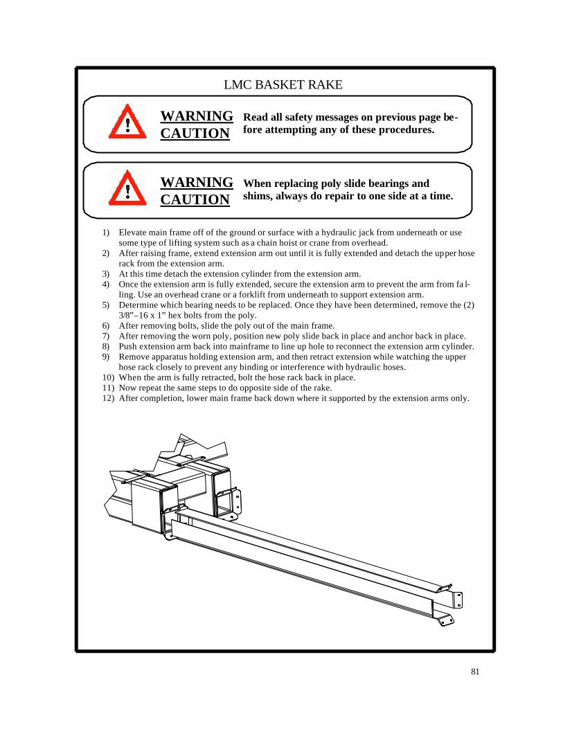
81
LMC BASKET RAKE
WARNING CAUTION
Read all safety messages on previous page be-fore attempting any of these procedures.
1) Elevate main frame off of the ground or surface with a hydraulic jack from underneath or use some type of lifting system such as a chain hoist or crane from overhead.
2) After raising frame, extend extension arm out until it is fully extended and detach the upper hose rack from the extension arm.
3) At this time detach the extension cylinder from the extension arm. 4) Once the extension arm is fully extended, secure the extension arm to prevent the arm from fa l-
ling. Use an overhead crane or a forklift from underneath to support extension arm. 5) Determine which bearing needs to be replaced. Once they have been determined, remove the (2)
3/8”–16 x 1” hex bolts from the poly. 6) After removing bolts, slide the poly out of the main frame. 7) After removing the worn poly, position new poly slide back in place and anchor back in place. 8) Push extension arm back into mainframe to line up hole to reconnect the extension arm cylinder. 9) Remove apparatus holding extension arm, and then retract extension while watching the upper
hose rack closely to prevent any binding or interference with hydraulic hoses. 10) When the arm is fully retracted, bolt the hose rack back in place. 11) Now repeat the same steps to do opposite side of the rake. 12) After completion, lower main frame back down where it supported by the extension arms only.
WARNING CAUTION
When replacing poly slide bearings and shims, always do repair to one side at a time.

82
MAINTENANCE LMC BASKET RAKE
WARNING: AVOID HIGH-PRESSURE FLUIDS
1. Escaping fluid under pressure can penetrate the skin causing serious injury. 2. Shut off tractor before connecting or disconnecting hydraulic lines at tractor. 3. Relieve pressure before unhooking hydraulic or other lines. Tighten all connections be-
fore applying pressure. Keep hand and body away from pinholes and components that may eject fluids under pressure. Use a piece of cardboard to search for leaks.
4. If ANY fluid is injected into the skin, a doctor familiar with this type of injury must surgi-cally remove it within a few hours.
Read all SAFETY MESSAGES at the beginning of this manual before attempting any of the procedures described in this section.
Regard especially the following: BEFORE APPROACHING OR ENTERING ANY MECHANISM TO SERVICE, INSPECT, OR MAKE ADJUSTMENTS:
A. LOWER UNIT TO THE GROUND. B. SHUT THE TRACTOR OFF. C. LOCK THE TRACTOR’S PARKING BRAKE. D. REMOVE THE KEY.
STAND CLEAR
Look around to be sure that if something slipped or accidentally moved that no harm would occur. Personnel operating and working with machinery must not wear loose, dangling or unbuttoned clothing that could tangle in machinery.
CAUTION

83
LMC BASKET RAKE
WARNING CAUTION
Read all safety messages on previous page be-fore attempting any of these procedures.
Spindle Replacement Instructions 1) Remove hub, Item 1, and bearings, Item 2. See Fig. 28 2) Remove spindle bolt, Item 3. 3) Remove spindle. 4) Replace spindle bolt, bearing, and hub.
Fig. 28

84
MAINTENANCE LMC BASKET RAKE
WARNING: AVOID HIGH-PRESSURE FLUIDS
1. Escaping fluid under pressure can penetrate the skin causing serious injury. 2. Shut off tractor before connecting or disconnecting hydraulic lines at tractor. 3. Relieve pressure before unhooking hydraulic or other lines. Tighten all connections be-
fore applying pressure. Keep hand and body away from pinholes and components that may eject fluids under pressure. Use a piece of cardboard to search for leaks.
4. If ANY fluid is injected into the skin, a doctor familiar with this type of injury must surgi-cally remove it within a few hours.
Read all SAFETY MESSAGES at the beginning of this manual before attempting any of the procedures described in this section.
Regard especially the following: BEFORE APPROACHING OR ENTERING ANY MECHANISM TO SERVICE, INSPECT, OR MAKE ADJUSTMENTS:
A. LOWER UNIT TO THE GROUND. B. SHUT THE TRACTOR OFF. C. LOCK THE TRACTOR’S PARKING BRAKE. D. REMOVE THE KEY.
STAND CLEAR
Look around to be sure that if something slipped or accidentally moved that no harm would occur. Personnel operating and working with machinery must not wear loose, dangling or unbuttoned clothing that could tangle in machinery.
CAUTION

85
LMC BASKET RAKE
WARNING CAUTION
Read all safety messages on previous page be-fore attempting any of these procedures.
Trouble Shooting – 8803 3 & 5 Spool Valve
1) After operating rake for a short period of time, check hydraulic fittings on valve for leaks.
Tighten fittings as required. See Fig. 30 & 31. 2) If any portion of the 3 or 5 spool valve does not function properly, check these items.
A. Center cable in control box per Fig. 30. B. Check for contamination in the valve ports.
1. Caution: make sure lines are not pressurized before removing hoses. 2. Remove hose, Item 1, from fitting. 3. Remove fitting, Item 2. 4. Remove hex bushing, Item 3. 5. Give visual check for debris in port. Then clean out port. 6. Replace components.
3) Debris can collect in 5-spool valve outer ports because of orifices in the valve.
Fig. 30
Fig. 31
Item 1 Item 2
Item 3

86
LMC BASKET RAKE
WARNING CAUTION
Read all safety messages on previous page be-fore attempting any of these procedures.
Electronic Control Box
1) If the control box, Item 1, is completely non-functional, check the fuse inside the control box. If the fuse is satisfactory, check the condition of the 12V battery source.
2) Electric Switches, Items 2,3,4,5,6
If only one function is non-operable, this could indicate a faulty switch. Or again, there could be a failure in the electrical cable.
3) The manual flow control, controls basket RPM – not to exceed 90 RPM.
95% OF MALFUNCTIONS ARE DUE TO INFREQUENT REPLACEMENT OF THE HY-DRAULIC FILTER.
NOTE: RAKE MUST BE HITCHED TO TRACTOR TO HAVE A GROUND CONNECTION
Fig. 32
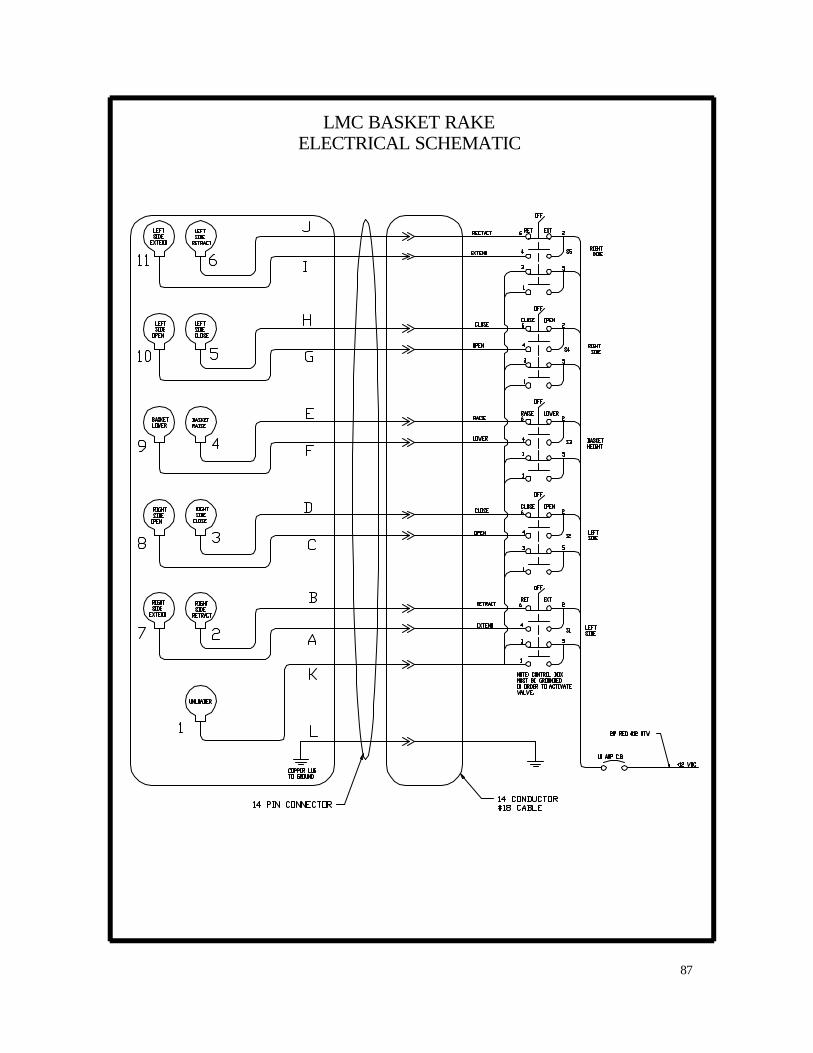
87
LMC BASKET RAKE ELECTRICAL SCHEMATIC

88
LMC BASKET RAKE TROUBLESHOOTING
PROBLEM CAUSE CORRECTION Tine bar breaking in half 1. Basket running too fast. 1. Slow basket speed down so
that it does not exceed 90 RPM
Front basket idler spindle breaking.
1. Basket height set too low, tines are digging into the ground
2. Basket running too fast
1. Adjust basket height so that tines do not touch the ground. Tines shoe be within 1/2” of the ground, but not actually in contact with the ground.
2. Slow basket speed down so that is does not exceed 90 RPM.
Disc wheels idler spindle breaking
1. Loose tine bar head bolts. 2. Tine bar head bearing. 3. Basket speed too fast.
1. Tighten tine bar head bolts. 2. Replace tine bar head bear-
ing. 3. Slow basket speed down so
that it does not exceed 90 RPM.
Baskets fail to operate when hydraulic remote valve is opened.
1. Check valve #79-211-88 in in the open position.
1. Replace hub, using new bolt, lock washer, and flat washer.
2. Remove and clean flow con-trol valve or replace the valve with a new one.
Baskets rise during field opera-tion.
1. System back pressure is ex-cessive, because return oil flow is restricted.
Read the HYDRAULICS section of OWNER’S MANUAL.
Rake function fails to operate. 1. Manual control cable out of adjustment.
2. Wire came off solenoid ad-justment. (Electric control valve only)
3. Solenoid defective. (Electric control valve only)
4. Hydraulic motor or cylinder is bypassing hydraulic oil in-ternally.
1. Adjust cable to take up slack. 2. Replace wire and tighten
spade connector. 3. Replace solenoid. 4. Install new seal kit in defec-
tive part.
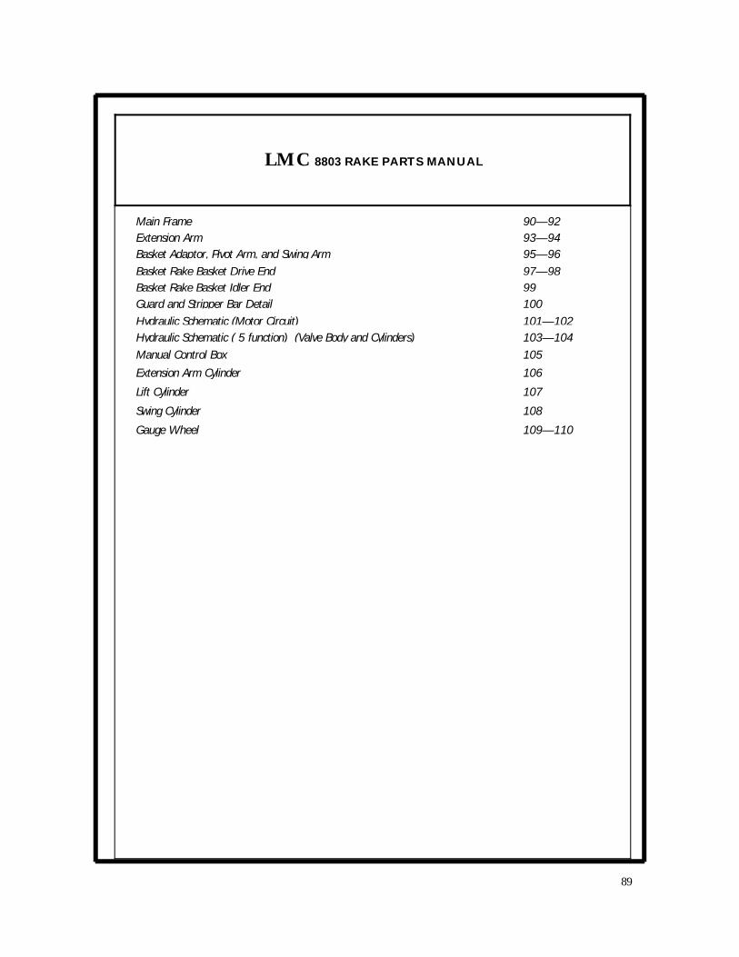
Main Frame 90—92 Extension Arm 93—94 Basket Adaptor, Pivot Arm, and Swing Arm 95—96 Basket Rake Basket Drive End 97—98 Basket Rake Basket Idler End 99 Guard and Stripper Bar Detail 100 Hydraulic Schematic (Motor Circuit) 101—102 Hydraulic Schematic ( 5 function) (Valve Body and Cylinders) 103—104 Manual Control Box 105
Extension Arm Cylinder 106
Lift Cylinder 107
Swing Cylinder 108
Gauge Wheel 109—110
LMC 8803 RAKE PARTS MANUAL
89

MAIN FRAME LMC 8803 RAKE
ITEM NO. DESCRIPTION PART NO. QUANTITY
1 WELDMENT, 8803 MAIN FRAME 85-1066-88 1
2 CYLINDER, 2-1/2” DIA. X 70” STROKE 79-1023-88 2
3 PLATE, 3/5 FUNCTION SPOOL VALVE MOUNT 93-1187-88 1
4 PIN, CLEVIS (WITH 2 COTTER PINS) 77-003-85 4
5 POLY, EXTENSION ARM SLIDE 68-1007-88 16
6 WELDMENT, 8803 EXTENSION ARM 85-1064-88 2
7 WELDMENT, RAKE JACK 85-1030-88 1
8 PIN, 5/8” X 3” BENT ARM 128007 1
9 PIN, #12, 3/16” X 3-1/2” HAIR 126004 1
10 WELDMENT, HICKEY BAR 85-014-85 1
VALVE BODY MOUNT PLATE FASTENERS
NOT SHOWN NUT, 5/16-18UNC STOVER HEX 1412-1000 8
NOT SHOWN WASHER, 5/16” SAE FLAT 4402-1000 8
NOT SHOWN BOLT, 5/16” X 1” GRADE 5 HEX 2816-1010 8
NOT SHOWN NUT, 3/8” UNC STOVER HEX 1412-1200 32
POLY SLIDE BEARING FASTENERS
NOT SHOWN WASHER, 3/8” SAE FLAT 4402-1200 32
NOT SHOWN BOLT, 3/8” X 1” GRADE 5 HEX 2816-1210 32
90
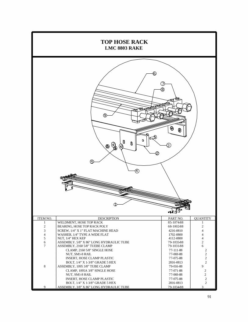
TOP HOSE RACK LMC 8803 RAKE
91
ITEM NO. DESCRIPTION PART NO. QUANTITY 1 WELDMENT, HOSE TOP RACK 85-1074-88 1 2 BEARING, HOSE TOP RACK POLY 68-1002-88 2 3 SCREW, 1/4” X 1” FLAT MACHINE HEAD 4216-0810 4 4 WASHER, 1/4” TYPE A WIDE FLAT 1702-0800 4 5 NUT, 1/4” HEX KEP 4112-0800 4 6 ASSEMBLY, 5/8” X 86” LONG HYDRAULIC TUBE 79-1035-88 2 7 ASSEMBLY, 2160 5/8” TUEBE CLAMP 79-1031-88 6 CLAMP, 2160 5/8” SINGLE HOSE 77-111-88 2 NUT, SM1-8 RAIL 77-069-88 2 INSERT, HOSE CLAMP PLASTIC 77-075-88 2 BOLT, 1/4” X 1-3/8” GRADE 5 HEX 2816-0813 2 8 ASSEMBLY, 1095 3/8” TUBE CLAMP 79-016-88 9 CLAMP, 1095A 3/8” SINGLE HOSE 77-071-88 2 NUT, SM1-8 RAIL 77-069-88 2 INSERT, HOSE CLAMP PLASTIC 77-075-88 2 BOLT, 1/4” X 1-3/8” GRADE 5 HEX 2816-0813 2 9 ASSEMBLY, 3/8” X 86” LONG HYDRAULIC TUBE 79-1034-88 3

FLOW CONTROL/ HOSE CLAMP LMC 8803 RAKE
92
ITEM NO. DESCRIPTION PART NO. QUANTITY 1 WELDMENT, 8803 RAKE MAIN FRAME 85-1067-88 1 2 VALVE, 16GPM FC51-1/2 FLOW CONTROL 79-211-88 1 3 NUT, 1/4” HEX KEP 4112-0800 2 4 BOLT, 1/4” X 2-1/2” LONG GR. 5 HEX 2816-0824 2 5 ELBOW, #10MJ—#8MP 90 DEG 79-1026-88 2 6 NIPPLE, #8MP—#8MP HEX 79-068-38 1
10 ASSEMBLY, 2160 5/8” TUEBE CLAMP 79-1031-88 9 CLAMP, 2160 5/8” SINGLE HOSE 77-111-88 2 NUT, SM1-8 RAIL 77-069-88 2 INSERT, HOSE CLAMP PLASTIC 77-075-88 2 BOLT, 1/4” X 1-3/8” GRADE 5 HEX 2816-0813 2
11 ASSEMBLY, 2127 1/2” TUBE CLAMP 79-012-88 6 CLAMP, 2127 1/2” SINGLE HOSE 77-072-88 2 NUT, SM1-8 RAIL 77-069-88 2 INSERT, HOSE CLAMP PLASTIC 77-075-88 2 BOLT, 1/4” X 1-3/8” GRADE 5 HEX 2816-0813 2
12 ASSEMBLY, 1/2” X 92” LONG HYDRAULIC TUBE 84-018-88 2
7 ELBOW, #8MP —#8FP STREET 90 DEG 79-069-88 1 8 VALVE, BALL 79-072-88 1 9 TEE, #10MJ—#10MJ—#8MP 79-1025-88 1
13 ASSEMBLY, 5/8” X 92” LONG HYDRAULIC TUBE 79-1032-88 2 14 ELBOW, #10MJ—#10FJS 45 DEG 79-1033-88 1

RIGHT/LEFT HAND EXTENSION ARM LMC 8803 RAKE
93

RIGHT/LEFT HAND EXTENSION ARM LMC 8803 RAKE
Quantities are for both left and right hand arms
94
ITEM NO. DESCRIPTION PART NO. QUANTITY
1 WELDMENT, 8803 EXTENSION ARM 85-1064-88 2
2 WELDMENT, 8803 UPPER AXLE TUBE 85-1073-88 2
3 WELDMENT, 8802 SWING ARM 85-1028-88 2
11 BUSHING, SWING ARM BRONZE 94-1016-88 4
4 PLATE, SWING ARM CYLINDER LUG 93-1090-88 2
NOT SHOWN BUSHING, HARDENED CONNEX 79-190-88 4
8 PIN, CLEVIS (WITH 2 COTTER PINS) 77-003-85 2
9 BOLT, 1/2” X 2” LONG GRADE 5 HEX 2816-1620 4
10 NUT, 1/2” STOVER HEX 1412-1600 4
12 WELDMENT, R.H. LOWER AXLE 85-1070-88 1
12 WELDMENT, L.H. LOWER AXLE (NOT SHOWN) 85-1071-88 1
13 ADAPTOR, #4MJ—#6MP STRAIGHT 79-228-88 4
14 NUT, 7/8” STOVER HEX 1412-2800 2
15 BOLT, 7/8” DIA. X 6” LONG GRADE 5 HEX 2816-2860 2
16 CLAMP, 3222/222D TWIN HOSE HALF 79-1028-38 4
17 PLATE, GD-3D CLAMP TOP COVER 77-037-38 2
18 BOLT, 5/16” X 2” LONG GRADE 5 HEX 2816-1020 2
5 CYLINDER, 2” DIA. X 8” STROKE ASAE 79-158-88 2
6 WELDMENT, SWING ARM CYLINDER PIN 85-1032-88 2
7 PIN, 3/16” X 2” LONG COTTER 77-015-04 2
19 CLAMP, 2127 1/2” SINGLE HOSE 77-072-88 4
20 PLATE, SCP2 CLAMP COVER 123011 2
21 BOLT, HB-2 STANDARD HEX 123012 2
22 WHEEL, 15 X 6LB, 6-6-4.62, 1.25+ 79-017-88 4
23 TIRE, 8.5/9-15K, SMOOTH 79-018-88 4
24 BOLT, 3/8” X 3” GRADE 5 HEX 2816-1230 4
25 ROUND, SPINDLE, Q888 HUB 96-034-88 4
26 NUT, 3/8” STOVER HEX 1412-1200 4
27 SEAL, Q888 HUB GREASE 77-006-02 4
28 BEARING, Q888 HUB INNER 77-007-02 4
29 HUB, Q888, 6 BOLT (WITH RACE) 77-001-02 4
30 BOLT, 1/2”-20 X 1-1/4” LONG LUG 77-013-02 24
31 BEARING, Q888 HUB OUTER 77-008-02 4
32 WASHER, Q888 HUB SPINDLE 77-005-02 4
33 NUT, 7/8” CASTLE (CNQ888) 77-004-02 4
34 PIN, 5/32” X 1-3/4” LONG COTTER 77-011-02 4
35 CAP, Q888 HUB DUST 77-012-02 4
36 BOLT, 1” X 2-1/2” LONG GRADE 8 HEX 2818-3224 12
37 WASHER, 1” DIA. LOCK 1602-3200 12
38 NUT, 1” GRADE 8 HEX 0814-3200 12

BASKET ADAPTOR, PIVOT ARM, AND SWING ARM LMC 8803 RAKE
95

BASKET ADAPTOR, PIVOT ARM, AND SWING ARM LMC 8803 RAKE
96
ITEM NO. DESCRIPTION PART NO. QUANTITY
1 & 9 PIN, CLEVIS (WITH 2 COTTER PINS) 77-003-85 1
2 BOLT, 7/16” X 3” #3 PLOW 0315-1430 4
3 NUT, 7/16” HEX 812-1400 4
4 BOLT, 1/2” X 1-1/2” GRADE 5 HEX 2816-1614 4
5 BOLT, 1/2’ X 3” GRADE 5 HEX 2816-1630 4
6 NUT, 1/2” HEX KEP 4112-1600 8
7 POLY, PIVOT ARM/BASKET BUMPER R.H. 68-1003-88 1
8 POLY, PIVOT ARM/BASKET BUMPER L.H. 68-1004-88 1
10 PIN, 3/16” X 2” LONG COTTER 77-015-04 4
11 TOP LINK, TL1630 CAT. 1 79-022-88 1
12 BEARING, KHFT 207-20 2 HOLE 79-025-88 2
13 PIN, 1/4” DIA. LYNCH 79-045-06 6
14 PIN, 3/4” DIA. X 3” CLEVIS 79-081-88 2
15 CYLINDER, 2” DIA. X 6” STROKE (SINGLE ACTING) 79-1006-88 1
16 FITTING, 5/16” DRIVE IN GREASE 79-6441-40 1
17 ASSEMBLY, GROUND PRESSURE ADJUSTING ARM 84-1025-88 2
WELDMENT, ADJUSTING ARM, GROUND PRESSURE 85-138-88 1
NUT, 3/4” HEX JAM 1014-2400 1
SCREW, SOC HEAD, 3/8”-16 UNC X 3/8” SET 1911-1203 1
BUSHING, UHMW BOLT GUIDE 77-066-88 1
WASHER, 3/4” FLAT SAE 4402-2400 2
SPRING, 1.234 O.D. X .191 WD X 9.5 LONG 79-204-88 1
BOLT, 3/4” X 9-1/2” GRADE 5 HEX 2816-24170 1
TRUNNION, BOLT GUIDE 95-001-88 1
18 WELDMENT, 8802 SWING ARM 85-1028-88 1
19 WELDMENT, BASKET RAKE PIVOT ARM 85-1031-88 1
20 WELDMENT, BASKET STAND OFF 85-128-88 2
21 BAR, BASKET LIFT CYLINDER MOUNT 93-1099-88 4
22 BUSHING, LINKAGE SPACER 94-084-88 4
23 PIN, CYLINDER CLEVIS 96-015-88 1
24 ADAPTOR, 11’-6” LH DELIVERY BASKET 85-1056-88 1
ADAPTOR, 11’-6” RH DELIVERY BASKET 85-1057-88 1
ADAPTOR, 10’-6” LH DELIVERY BASKET 85-1058-88 1
ADAPTOR, 10’-6” RH DELIVERY BASKET 85-1059-88 1

TYPICAL BASKET DRIVE END LMC 8803 RAKE
97
RH DELIVERY SHOWN
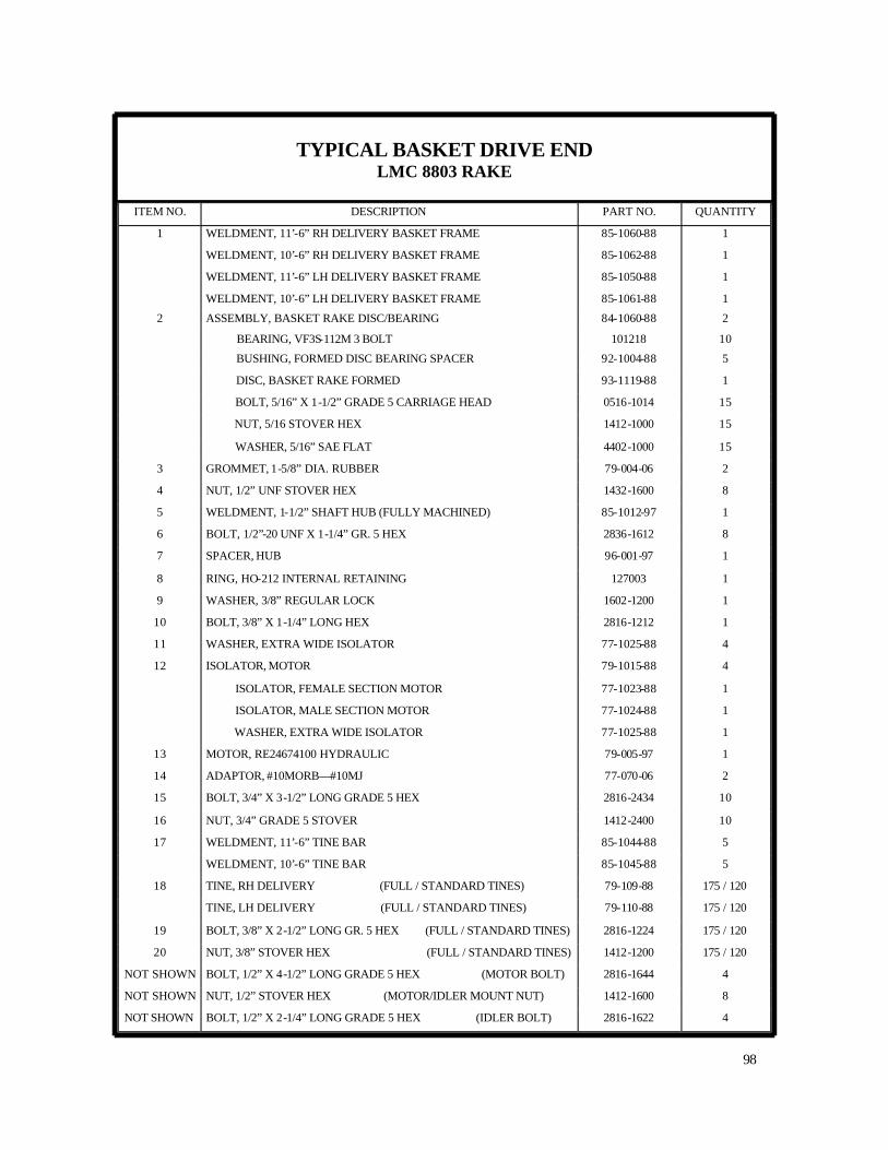
TYPICAL BASKET DRIVE END LMC 8803 RAKE
98
ITEM NO. DESCRIPTION PART NO. QUANTITY
1 WELDMENT, 11’-6” RH DELIVERY BASKET FRAME 85-1060-88 1
WELDMENT, 10’-6” RH DELIVERY BASKET FRAME 85-1062-88 1
WELDMENT, 11’-6” LH DELIVERY BASKET FRAME 85-1050-88 1
WELDMENT, 10’-6” LH DELIVERY BASKET FRAME 85-1061-88 1
2 ASSEMBLY, BASKET RAKE DISC/BEARING 84-1060-88 2
BEARING, VF3S-112M 3 BOLT 101218 10
BUSHING, FORMED DISC BEARING SPACER 92-1004-88 5
DISC, BASKET RAKE FORMED 93-1119-88 1
BOLT, 5/16” X 1-1/2” GRADE 5 CARRIAGE HEAD 0516-1014 15
NUT, 5/16 STOVER HEX 1412-1000 15
WASHER, 5/16” SAE FLAT 4402-1000 15
3 GROMMET, 1-5/8” DIA. RUBBER 79-004-06 2
4 NUT, 1/2” UNF STOVER HEX 1432-1600 8
5 WELDMENT, 1-1/2” SHAFT HUB (FULLY MACHINED) 85-1012-97 1
6 BOLT, 1/2”-20 UNF X 1-1/4” GR. 5 HEX 2836-1612 8
7 SPACER, HUB 96-001-97 1
8 RING, HO-212 INTERNAL RETAINING 127003 1
9 WASHER, 3/8” REGULAR LOCK 1602-1200 1
10 BOLT, 3/8” X 1-1/4” LONG HEX 2816-1212 1
11 WASHER, EXTRA WIDE ISOLATOR 77-1025-88 4
12 ISOLATOR, MOTOR 79-1015-88 4
ISOLATOR, FEMALE SECTION MOTOR 77-1023-88 1
ISOLATOR, MALE SECTION MOTOR 77-1024-88 1
WASHER, EXTRA WIDE ISOLATOR 77-1025-88 1
13 MOTOR, RE24674100 HYDRAULIC 79-005-97 1
14 ADAPTOR, #10MORB—#10MJ 77-070-06 2
15 BOLT, 3/4” X 3-1/2” LONG GRADE 5 HEX 2816-2434 10
16 NUT, 3/4” GRADE 5 STOVER 1412-2400 10
17 WELDMENT, 11’-6” TINE BAR 85-1044-88 5
WELDMENT, 10’-6” TINE BAR 85-1045-88 5
18 TINE, RH DELIVERY (FULL / STANDARD TINES) 79-109-88 175 / 120
TINE, LH DELIVERY (FULL / STANDARD TINES) 79-110-88 175 / 120
19 BOLT, 3/8” X 2-1/2” LONG GR. 5 HEX (FULL / STANDARD TINES) 2816-1224 175 / 120
20 NUT, 3/8” STOVER HEX (FULL / STANDARD TINES) 1412-1200 175 / 120
NOT SHOWN BOLT, 1/2” X 4-1/2” LONG GRADE 5 HEX (MOTOR BOLT) 2816-1644 4
NOT SHOWN NUT, 1/2” STOVER HEX (MOTOR/IDLER MOUNT NUT) 1412-1600 8
NOT SHOWN BOLT, 1/2” X 2-1/4” LONG GRADE 5 HEX (IDLER BOLT) 2816-1622 4

TYPICAL BASKET IDLER END LMC 8803 RAKE
99
ITEM NO. DESCRIPTION PART NO. QUANTITY
1 WELDMENT, BASKET IDLER HUB SHAFT 85-1011-88 1
2 SEAL, 1-1/2” SINGLE LIP 77-006-87 1
3 BEARING, #L44643 77-045-88 2
4 HUB, IDLER (WITH CUPS) 77-012-87 1
5 WASHER, SW625 SPINDLE 77-003-87 1
6 NUT, 5/8” UNF CASTLE 77-001-87 1
7 PIN, 5/16” X 1-1/2’ LONG COTTER 77-002-87 1
8 CAP, HUB DUST 77-007-87 1
RH DELIVERY SHOWN
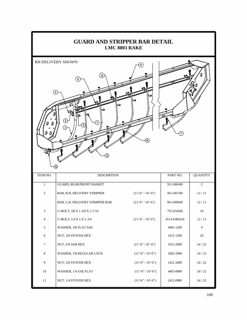
GUARD AND STRIPPER BAR DETAIL LMC 8803 RAKE
100
ITEM NO. DESCRIPTION PART NO. QUANTITY
1 GUARD, REAR/FRONT BASKET 92-1000-88 2
2 BAR, R.H. DELIVERY STRIPPER (11’-6” / 10’-6”) 96-1007-88 12 / 11
BAR, L.H. DELIVERY STRIPPER BAR (11’-6” / 10’-6”) 96-1008-88 12 / 11
3 U-BOLT, 3/8 X 1-3/8 X 2-7/16 79-1018-88 10
4 U-BOLT, 1/4 X 1 X 1-3/4 (11’-6” / 10’-6”) 45114-081610 12 / 11
5 WASHER, 3/8 FLAT SAE 4402-1200 4
6 NUT, 3/8 STOVER HEX 1412-1200 20
7 NUT, 5/8 JAM HEX (11’-6” / 10’-6”) 1012-2000 24 / 22
8 WASHER, 5/8 REGULAR LOCK (11’-6” / 10’-6”) 1602-2000 24 / 22
9 NUT, 5/8 STOVER HEX (11’-6” / 10’-6”) 1412-2000 24 / 22
10 WASHER, 1/4 SAE FLAT (11’-6” / 10’-6”) 4402-0800 24 / 22
11 NUT, 1/4 STOVER HEX (11’-6” / 10’-6”) 1412-0800 24 / 22
RH DELIVERY SHOWN
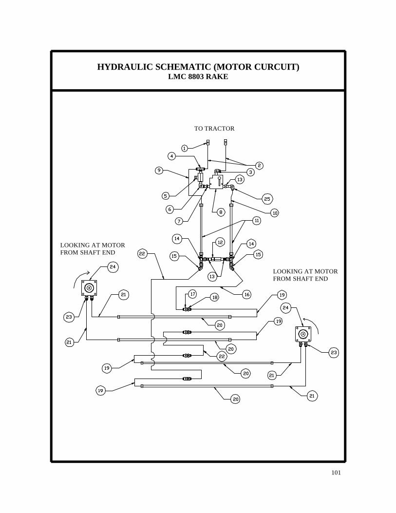
HYDRAULIC SCHEMATIC (MOTOR CURCUIT) LMC 8803 RAKE
101
TO TRACTOR
LOOKING AT MOTOR FROM SHAFT END
LOOKING AT MOTOR FROM SHAFT END
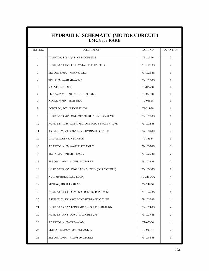
HYDRAULIC SCHEMATIC (MOTOR CURCUIT) LMC 8803 RAKE
102
ITEM NO. DESCRIPTION PART NO. QUANTITY
1 ADAPTOR, S71-4 QUICK DISCONNECT 79-212-36 2
2 HOSE, 5/8” X 66” LONG VALVE TO TRACTOR 79-1027-88 2
3 ELBOW, #10MJ—#8MP 90 DEG 79-1026-88 1
4 TEE, #10MJ—#10MJ—#8MP 79-1025-88 1
5 VALVE, 1/2” BALL 79-072-88 1
6 ELBOW, #8MP —#8FP STREET 90 DEG 79-069-88 1
7 NIPPLE, #8MP—#8MP HEX 79-068-38 1
8 CONTROL, FC51 E TYPE FLOW 79-211-88 1
9 HOSE, 5/8” X 20” LONG MOTOR RETURN TO VALVE 79-1029-88 1
10 HOSE, 5/8” X 18” LONG MOTOR SUPPLY FROM VALVE 79-1028-88 1
11 ASSEMBLY, 5/8” X 92” LONG HYDRAULIC TUBE 79-1032-88 2
12 VALVE, DPIFF-4P-65 CHECK 79-146-88 1
13 ADAPTOR, #10MJ—#8MP STRAIGHT 79-1037-38 3
14 TEE, #10MJ—#10MJ—#10FJS 79-1030-88 2
15 ELBOW, #10MJ—#10FJS 45 DEGREE 79-1033-88 2
16 HOSE, 5/8” X 45” LONG RACK SUPPLY (FOR MOTORS) 79-1036-88 1
17 NUT, #10 BULKHEAD LOCK 79-243-06A 4
18 FITTING, #10 BULKHEAD 79-243-06 4
19 HOSE, 5/8” X 64” LONG BOTTOM TO TOP RACK 79-1039-88 4
20 ASSEMBLY, 5/8” X 86” LONG HYDRAULIC TUBE 79-1035-88 4
21 HOSE, 5/8” X 120” LONG MOTOR SUPPLY/RETURN 79-1024-88 4
22 HOSE, 5/8” X 68” LONG RACK RETURN 79-1037-88 2
23 ADAPTOR, #10MORB—#10MJ 77-070-06 4
24 MOTOR, RE24674100 HYDRAULIC 79-005-97 2
25 ELBOW, #10MJ—#10FJS 90 DEGREE 79-1052-88 1
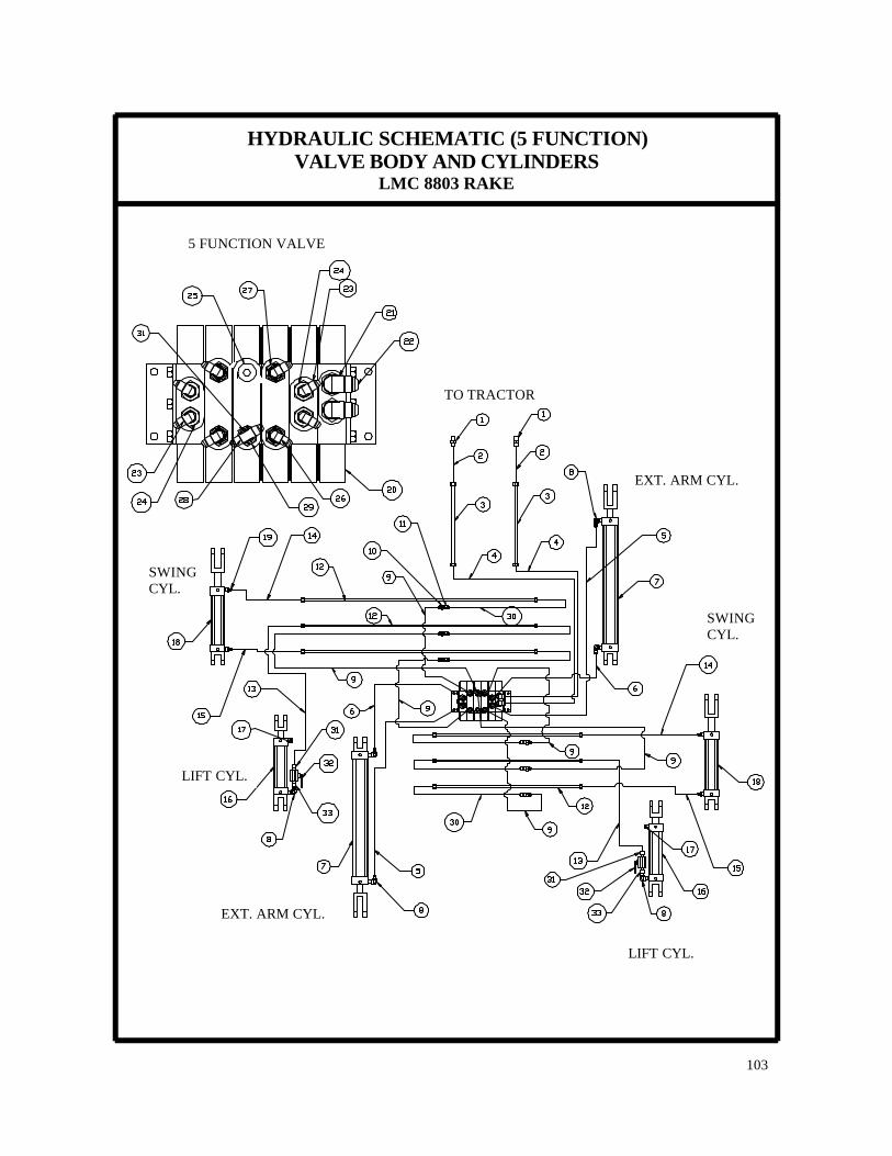
HYDRAULIC SCHEMATIC (5 FUNCTION) VALVE BODY AND CYLINDERS
LMC 8803 RAKE
103
5 FUNCTION VALVE
EXT. ARM CYL.
EXT. ARM CYL.
LIFT CYL.
LIFT CYL.
TO TRACTOR
SWING CYL.
SWING CYL.

HYDRAULIC SCHEMATIC (5 FUNCTION) VALVE BODY AND CYLINDERS
LMC 8803 RAKE
104
ITEM NO. DESCRIPTION PART NO. QUANTITY
1 ADAPTOR, S71-4 QUICK DISCONNECT 79-212-36 2
2 HOSE, 1/2” X 66” LONG RAKE SUPPLY/RETURN 79-068-88 2
3 ASSEMBLY, 1/2” X 92” LONG HYDRAULIC TUBE 84-018-88 2
4 HOSE, 1/2” X 51” LONG VALVE SUPPLY/RETURN 79-015-88 2
5 HOSE, 1/4” X 46” LONG EXTENSION ARM CYLINDER 79-1043-88 2
6 HOSE, 1/4” X 60” LONG EXTENSION ARM CYLINDER 79-1042-88 2
7 CYLINDER, 2-1/2” DIA. X 70” STROKE 79-1023-88 2
8 ELBOW, #6MJ—#6MP 90 DEGREE 79-1000-88 6
9 HOSE, 1/4” X 30” LONG VALVE TO RACK 79-101-88 6
10 FITTING, #6 BULKHEAD 79-013-88 6
11 NUT, #6 BULKHEAD LOCK 79-1002-88 6
12 ASSEMBLY, 3/8” X 86” LONG HYDRAULIC TUBE 79-1034-88 6
13 HOSE, 1/4” X 80” LONG BASKET LIFT CYLINDER 79-167-88 2
14 HOSE, 1/4” X 42” LONG SWING CYLINDER 79-064-88 2
15 HOSE, 1/4” X 42” LONG SWING CYLINDER 79-064-88 2
16 CYLINDER, 6” SINGLE ACTING BASKET LIFT 79-1006-88 2
17 BREATHER, 3/8” BRASS 79-172-88 2
18 CYLINDER, 2 X 8 SWING 79-158-88 2
19 ADAPTOR, #4MJ—#6MP STRAIGHT 79-228-88 4
20 VALVE, 8803 5 FUNCTION ELECTRIC 79-1041-88 1
21 ADAPTOR, #8MJ—#10MORB STRAIGHT 79-050-88 2
22 ELBOW, #8MJ—#8FJS 90 DEGREE 77-058-06 2
23 ELBOW, #4MJ—#4FJS 90 DEGREE 79-097-88 4
24 ADAPTOR, #4MJ—#8MORB STRAIGHT 79-169-88 4
25 PLUG, #8MORB HOLLOW HEX 79-029-85 1
26 ELBOW, #4MJ—#4MORB 90 DEG 79-052-88 4
27 ADAPTOR, #8MORB—#4FORB W/ 1/16 ORIFICE 79-197-88 4
28 TEE, #4MJ—#4MJ—#4FJS SWIVEL BRANCH 79-099-88 1
29 ADAPTOR, #8MORB—#4FORB 79-054-88 1
30 HOSE, 1/4” X 64” LONG BOTTOM TO TOP RACK 79-1038-88 6
NOT SHOWN KIT, 8803 5 FUNCTION CONTROL BOX 72-059-88 1
BAR, BUSS 72-057-88 1
BOX, 5 FUNCTION ELECTRICAL CONTROL 79-223-88 1
HARNESS, 21 FT. WIRING 79-224-88 1
31 ADAPTOR, #6MP —#6MJ STRAIGHT 79-1001-88 2
NOT SHOWN ADAPTOR, #8MJ UNION 79-1014-38 2
32 VALVE, 3/8” NPT BALL 79-1050-88 2
33 ADAPTOR, #6MP —#6FJS STRAIGHT 79-1051-88 2
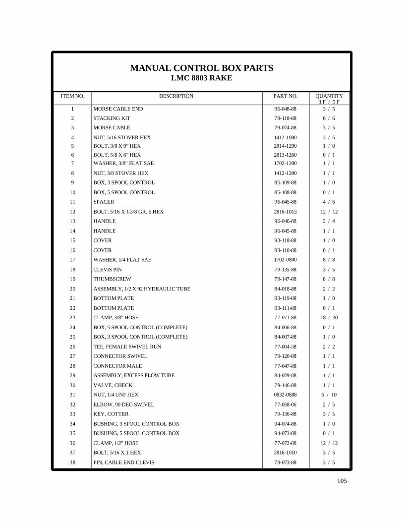
MANUAL CONTROL BOX PARTS LMC 8803 RAKE
105
ITEM NO. DESCRIPTION PART NO. QUANTITY 3 F / 5 F
1 MORSE CABLE END 96-048-88 3 / 5
2 STACKING KIT 79-118-88 6 / 6
3 MORSE CABLE 79-074-88 3 / 5
4 NUT, 5/16 STOVER HEX 1412-1000 3 / 5
5 BOLT, 3/8 X 9” HEX 2814-1290 1 / 0
6 BOLT, 5/8 X 6” HEX 2813-1260 0 / 1
7 WASHER, 3/8” FLAT SAE 1702-1200 1 / 1
8 NUT, 3/8 STOVER HEX 1412-1200 1 / 1
9 BOX, 3 SPOOL CONTROL 85-109-88 1 / 0
10 BOX, 5 SPOOL CONTROL 85-108-88 0 / 1
11 SPACER 96-045-88 4 / 6
12 BOLT, 5/16 X 1-3/8 GR. 5 HEX 2816-1013 12 / 12
13 HANDLE 96-046-88 2 / 4
14 HANDLE 96-045-88 1 / 1
15 COVER 93-118-88 1 / 0
16 COVER 93-110-88 0 / 1
17 WASHER, 1/4 FLAT SAE 1702-0800 8 / 8
18 CLEVIS PIN 79-135-88 3 / 5
19 THUMBSCREW 79-147-88 8 / 8
20 ASSEMBLY, 1/2 X 92 HYDRAULIC TUBE 84-018-88 2 / 2
21 BOTTOM PLATE 93-119-88 1 / 0
22 BOTTOM PLATE 93-111-88 0 / 1
23 CLAMP, 3/8” HOSE 77-071-88 18 / 30
24 BOX, 5 SPOOL CONTROL (COMPLETE) 84-006-88 0 / 1
25 BOX, 3 SPOOL CONTROL (COMPLETE) 84-007-88 1 / 0
26 TEE, FEMALE SWIVEL RUN 77-004-38 2 / 2
27 CONNECTOR SWIVEL 79-120-88 1 / 1
28 CONNECTOR MALE 77-047-88 1 / 1
29 ASSEMBLY, EXCESS FLOW TUBE 84-029-88 1 / 1
30 VALVE, CHECK 79-146-88 1 / 1
31 NUT, 1/4 UNF HEX 0832-0888 6 / 10
32 ELBOW, 90 DEG SWIVEL 77-058-06 2 / 5
33 KEY, COTTER 79-136-88 3 / 5
34 BUSHING, 3 SPOOL CONTROL BOX 94-074-88 1 / 0
35 BUSHING, 5 SPOOL CONTROL BOX 94-073-88 0 / 1
36 CLAMP, 1/2” HOSE 77-072-88 12 / 12
37 BOLT, 5/16 X 1 HEX 2816-1010 3 / 5
38 PIN, CABLE END CLEVIS 79-073-88 3 / 5

EXTENSION ARM CYLINDER LMC 8803 RAKE
106
ITEM NO. DESCRIPTION PART NO. QUANTITY
1 ROD CLEVIS 77-1035-88 2
2 CYLINDER ROD 77-1036-88 2
3 SEAL 77-1037-88 2
4 ROD CAP 77-1038-88 2
5 BACKUP WASHER 77-1039-88 4
6 O-RING 77-1040-88 4
7 ROD SEAL 77-1041-88 2
8 PISTON 77-1042-88 2
9 NUT, 3/4” UNF HEX LOCK 1411-2400 2
10 BARREL 77-1043-88 2
11 NUT, 3/8” HEX 0811-1200 16
12 O-RING 77-1044-88 2
13 PISTON RING 77-1045-88 2
14 CLEVIS CAP 77-1046-88 2
NOT SHOWN SEAL KIT 77-1048-88 2
15 TIE ROD 77-1047-88 8
79-1023-88

LIFT CYLINDER LMC 8803 RAKE
107
79-1006-88
ITEM NO. DESCRIPTION PART NO. QUANTITY
1 ROD CLEVIS 77-133-88 2
2 CYLINDER ROD 77-1030-88 2
3 SEAL 77-135-88 2
4 ROD CAP 77-136-88 2
5 BACKUP WASHER 77-137-88 4
6 O-RING 77-138-88 4
7 ROD SEAL 77-139-88 2
8 PISTON 77-1031-88 2
9 NUT, 3/4” UNF HEX LOCK 1411-2400 2
10 BARREL 77-141-88 2
11 NUT, 3/8” HEX 0811-1200 16
12 SEAL, PISTON 77-1032-88 2
13 PISTON RING 77-143-88 2
14 CLEVIS CAP 77-144-88 2
NOT SHOWN SEAL KIT 77-1034-88 2
15 TIE ROD 77-1033-88 8

SWING CYLINDER LMC 8803 RAKE
108
ITEM NO. DESCRIPTION PART NO. QUANTITY
1 ROD CLEVIS 77-133-88 2
2 CYLINDER ROD 77-134-88 2
3 SEAL 77-135-88 2
4 ROD CAP 77-136-88 2
5 BACKUP WASHER 77-137-88 4
6 O-RING 77-138-88 4
7 ROD SEAL 77-139-88 2
8 PISTON 77-140-88 2
9 NUT, 3/4” UNF HEX LOCK 1411-2400 2
10 BARREL 77-141-88 2
11 NUT, 3/8” HEX 0811-1200 16
12 O-RING 77-142-88 2
13 PISTON RING 77-143-88 2
14 CLEVIS CAP 77-144-88 2
NOT SHOWN SEAL KIT 77-152-88 2
15 TIE ROD 77-145-88 8
79-158-88

GAUGE WHEEL LMC 8803 RAKE
109

GAUGE WHEEL LMC 8803 RAKE
110
ITEM NO. DESCRIPTION PART NO. QUANTITY
1 GAUGE WHEEL MOUNT, FRONT RIGHT 85-1042-88 1
GAUGE WHEEL MOUNT, FRONT LEFT 85-1041-88 1
2 ARM, PIVOT 85-1043-88 1
3 ADJUSTABLE ARM 79-022-88 1
4 BOLT, 3/4” X 5” LONG HEX 2816-2450 1
5 NUT, 3/4” STOVER HEX 1412-2400 2
6 BOLT, 3/4” X 8” LONG HEX 2816-2480 1
7 PIN, 3/4” X 3-3/4” CLEVIS 79-082-88 2
8 PIN, 3/16” X 2” COTTER 77-015-04 2
9 GREASE FITTING 79-6441-40 1
10 BUSHING, GAUGE WHEEL PIVOT 94-032-88 1
11 YOKE 85-020-88 1
12 ASSEMBLY, TIRE AND WHEEL 79-177-88 1
NOT SHOWN PIN, 1/4” X 3” COTTER 79-089-88 1
NOT SHOWN U-BOLT, 1/2 X 2” X 3” 79-006-22 2
NOT SHOWN NUT, 1/2” STOVER HEX 1412-1600 4

NOTES
111

NOTES
112

DATE SERVICED SERVICE PERFORMED
PARTS REPLACED
MAINTENANCE RECORD
113