Embed Size (px)
Citation preview
Pierre Clavel agrees, pointing out the W-CDMA network’s
sensitivity to inter-cell soft handover areas is the main culprit.
“Unlike TDMA-based GSM, UMTS is W-CDMA-based and
provides only a 5 MHz wide spectrum shared according to
coding across all subscribers in the cell,” explains Clavel.
“Cell overlap quickly eats into capacity and increases
interference problems.” The answer, he believes, will be a
focus on more precision tailoring of the antenna ‘footprint’.
The TMA debateThe use of tower mounted amplifiers (TMAs) in the
UMTS network also raises some curly questions and fierce
debates. The argument for TMAs in UMTS runs like this –
as the W-CDMA modulation spreads the signal thinly across the
5 MHz allocated band, the uplink signal in particular is very
close to the physical noise limit.
Not so easy says Helmut Heinz. “Inter-cell interference
is a big issue with W-CDMA. This means the UMTS system is
actually more C/I-limited than the GSM 2G system,” Heinz
explains. “The TMAs will bring everything up, not just the
wanted signal!”
Nevertheless Heinz predicts that TMAs will become
‘more or less standard’ in the new UMTS networks. “These
[TMAs] are so well established around the world in 1800 GSM.
It’s a trend I suppose.”
RFS’s Michel agrees, suggesting that at least in the
beginning, TMAs will be standard fare. “We plan to develop
3G TMAs, because most OEMs at this stage intend to use them.
This may change, as increases in subscriber base and traffic over
time will cause cell densification and could actually decrease
this early need for sensitivity.”
3G RF - the long termJust how 3G deployment will pan out is, at this stage,
anyone’s guess. Kari Junttila believes that many operators will
tackle it as they’ve done with GSM and DCS – an initial dash
for coverage, then revert to focus on capacity, customisation
and network optimisation. But, he points out, there are other
options. “You can even consider starting with macro-micro cells
in areas where you know you’ll have large capacity and will
need high quality service. This avoids the cost of reworking
older macros at a later stage. It comes down to a compromise
between network financing and quality.”
According to Clavel, the 3G-future will usher in even
more advanced RF technology to meet maturing network
needs. Miniaturisation will be the order of the day, as
will customisation.
“We’re also predicting an even greater move towards
integration of services into the antenna – multi-bands, filters
and other active devices, all packed into a compact antenna
package,” says Clavel. “Ultimately, we’ll be providing higher
levels of customisation, so that antennas will be tailored to
precisely match base station characteristics.”
Back in today’s time zone, the prime objective of
first-phase 3G deployment will remain implementation speed.
A comprehensive cache of base station RF options – single,
multi- and broadband antennas, multiplexers, filters and
TMAs – will be the weaponry required to win on this all-
important first 3G battlefield.
Company BackgroundRadio Frequency Systems is a global designer and
manufacturer of antenna and cable systems, offering total-
package solutions for wireless infrastructure.
RFS serves operators, OEMs, distributors and system
integrators in the broadcast, cellular, land-mobile and microwave
market sectors. An ISO-compliant organisation with cutting-edge
engineering capabilities, innovative product design, proven field
support and customer service facilities that span the globe, RFS
is a leader in wireless communications.
Technical enquiries:Pierre Clavel, Cellular Antenna Product Manager,
Radio Frequency Systems,
Telephone +33 134 236032.
E-mail: [email protected]
Patrick C. Nobileau, VP Mobile Antenna Systems
Radio Frequency Systems Inc,
Telephone +1 704 426 6017
E-mail: [email protected]
R F S T h e C l e a r C h o i c e i n W i r e l e s s ™
RF OPTIONSFOR 3G
FAST TRACK
“Radio FrequencySystems explores
how cellular operatorswill practically realise
3G networks from a base station
RF perspective.”
Please visit us on the internet at www.rfsworld.com
RFS Mercosul
Tel: +55-11 4781 2433
Fax: +55-11 4781 1651
RFS China
Tel: +86-21 5774 4500
Fax: +86-21 5774 4633
RFS Americas
Tel: +1-203 630 3311
Fax: +1-203 821 3850
RFS Australia
Tel: +61-3 9751 8400
Fax: +61-3 9761 5711
RFS Europe
Tel: +49-511 676 2520
Fax: +49-511 676 2521
• Bangkok• Beijing• Bezons • Calgary• Charlotte• Corvallis• Glendale Heights
• Hannover• Hillerød • Hong Kong• Jakarta• Johannesburg• Lannion• London
• Markham• Marlboro• Melbourne• Meriden• Mexico• Miami• Monza
• Moscow• Phoenix• Richardson• Sào Paulo• Shanghai• Singapore• Trignac
RADIO FREQUENCY SYSTEMS
But this, he says, is minor when
compared to the GSM-to-UMTS migration –
“the move from GSM to UMTS is not simply
a shift in operating spectrum; it is a
complete change in RF technology. It will
require entirely new infrastructure to be
implemented – and at a pace we’ve not
seen before!”
High speed This raises an interesting issue. How
will new base station infrastructure be
deployed at record speeds in regions such
as Europe where base station site
acquisition is all but impossible?
According to many in the industry, co-
siting and even multiband antennas and
feeder cable sharing will become a 3G
practical reality. Siemens’ director of RF
engineering, Helmut Heinz, believes the
financial and timing realities of realising
virgin 3G sites will outweigh the
disadvantages of co-siting. “The true
cost of a new site – the concrete, the
towers, mains, air conditioning and the
site itself – is very much comparable to the
cost of the base station alone. Factoring
this in with the difficulty of acquiring new
sites, I’m sure operators will try to use as
many existing sites as possible, particularly
in the first phase.”
Environmental issues, he says,
will force many operators to also
consider multi-band antenna
deployment. In particularly
congested urban sites,
multiplexed feeder cable
solutions may also
prove necessary where
new feeder cabling
is difficult.
Others view 3G
deployment from a
more purist RF aspect,
citing limited flexibility
in cell planning and
intermodulation as
long-term drawback to
co-location. Radio network
planning manager with new
Spanish UMTS-only operator XFERA,
Kari Junttila, supports this view. Junttila
recently completed five years with Finnish
operator Sonera (formerly Telecom Finland),
where he was instrumental in guiding the
operator through its first phase 3G roll-out.
“At Sonera we tried to avoid co-siting
wherever possible,” Junttila says. “In my
opinion this is the greatest 3G deployment
challenge – to keep the two radio systems
separate.” Nevertheless, he acknowledges
that co-siting and even antenna sharing will
be a necessity in some cases. “We all know
about the lack of antenna sites. From a
global perspective, co-siting is certainly not
the best technical solution, but it is
probably the easiest solution.”
Antenna optionsRFS’s Clavel acknowledges that
gauging market opinion at such a volatile
stage is difficult, but believes a broad and
innovative antenna product set will
ultimately best equip operators to
meet the 3G challenge. “The need to
deploy 3G quickly will place operators in
situations where decisions will need to be
made almost instantly,” reflects Clavel.
“We’re endeavoring to provide the widest
antenna product set to ensure optimal site
fit-out flexibility.”
The RFS 3G antenna series includes a
family of cross-polarised UMTS-only antenna
and a series of dual-band DCS/UMTS
antennas, both launched during the
European summer 2000. Clavel describes
the four-connector dual band series as
‘antenna à la carte’, as the company plans
to offer these in customer selected
combinations of existing DCS and UMTS
antenna range, fitted within a DCS antenna-
sized radome.
‘Antenna à la carte’ will provide a
range of independently factory-set fixed
electrical tilts (FET) and variable electrical
tilts (VET) for each band. This, Clavel
emphasises, offers huge advantage over
conventional broadband 3G antenna
solutions. “Providing such as VET on a
band-by-band basis in a single multi-band
package allows the operator to achieve fully
optimised radiation patterns. ‘Antenna à la
carte’ permits the user to realise completely
independent optimisation and to evolve this
optimisation with the network
requirements.”
Launched in May 2000, RFS has
also produced a broadband two-connector
antenna for the DCS/UMTS market.
The advantage of this product, Clavel
explains, is that it can grow with the
operator’s 3G needs. “Despite imminent
UMTS roll-out, operators continue the
deployment of 1800 spectrum as an
upgrade of existing GSM network. The
operators can use the broadband antenna
today for DCS 1800 layout – and if a co-
sited UMTS service is required in the future,
this can be realised by fitting a diplexer,”
Clavel points out.
Triple band antenna technology -
providing UMTS, DCS and GSM services
from a single antenna – is also being
developed, with an RFS tri-band
prototype successfully deployed at
sites across Europe. “This is a
world’s first; a three times fixed
tilt antenna in the same form
factor as our dual band
antenna. The main area we see
these being used is by
operators currently operating
dual band GSM/DCS networks.”
A dual band GSM/UMTS antenna
also been developed by RFS,
based on the tri-band technology.
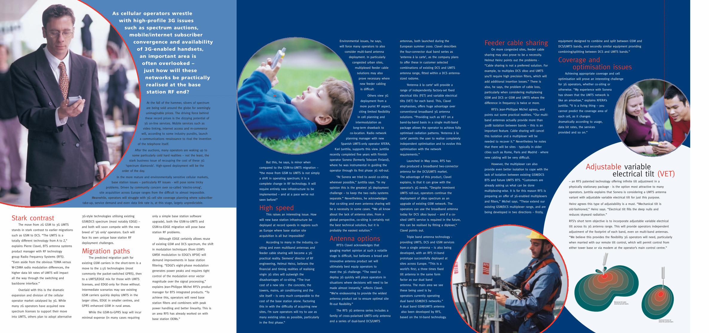
Mechanical tilt yields distorted azimuth beams.
Electrical tilt does notdistort the azimuth beam.
As cellular operators wrestle with high-profile 3G issues
such as spectrum auctions,mobile/internet subscriber
convergence and availabilityof 3G-enabled handsets, an important area is often overlooked – just how will thesenetworks be practicallyrealised at the basestation RF end?
At the fall of the hammer, slivers of spectrum
are being sold around the globe for seemingly
unimaginable prices. The driving force behind
these record prices is the dizzying potential of
3G on-line services. Mobile services such as
video linking, internet access and m-commerce
will, according to some industry pundits, launch
a communications renaissance to rival the invention
of the telephone itself.
After the auctions, many operators are waking up to
some particularly cold hard realities – not the least, the
stark business issue of recouping the cost of these 3G
‘spectrum diamonds’. High-speed deployment will be the
order of the day.
In the more mature and environmentally sensitive cellular markets,
base station issues – particularly RF issues - will pose some tricky
problems. Driven by community concern over so-called ‘electro-smog’,
site acquisition across Europe ranges from the difficult to almost impossible.
Meanwhile, operators will struggle with 3G cell site coverage planning where subscriber
take-up, service demand and even data link rate is, at this stage, largely unpredictable.
equipment designed to combine and split between GSM and
DCS/UMTS bands, and secondly similar equipment providing
combining/splitting between DCS and UMTS bands.”
Coverage andoptimisation issues
Achieving appropriate coverage and cell
optimisation will prove an interesting challenge
for 3G operators, whether co-siting or
otherwise. “My experience with Sonera
has shown that the UMTS network is
like an amoebae,” explains XFERA’s
Junttila. “It is a living thing – you
cannot predict the coverage area of
each cell, as it changes
dramatically according to usage,
data bit rates, the services
provided and so on.”
Feeder cable sharingOn more congested sites, feeder cable
sharing may also prove to be a necessity.
Helmut Heinz points out the problems -
“Cable sharing is not a preferred solution. For
example, to multiplex DCS 1800 and UMTS
you’ll require high precision filters, which will
add additional insertion losses.” There is
also, he says, the problem of cable loss,
particularly when considering multiplexing
GSM and DCS or GSM and UMTS where the
difference in frequency is twice or more.
RFS’s Jean-Phillippe Michel agrees, and
points out some practical realities. “Our multi-
band antennas actually provide more than
30dB isolation between bands – this is an
important feature. Cable sharing will cancel
this isolation and a multiplexer will be
needed to recover it.” Nevertheless he notes
that there will be sites - typically in older
cities such as Rome, Paris and Madrid - where
new cabling will be very difficult.
However, the multiplexer can also
provide even better isolation to cope with the
lack of isolation between existing GSM/DCS
BTS and future UMTS BTS. “Customers are
already asking us what can be done
multiplexing-wise. It is for this reason RFS is
preparing an offer of 3G-enabled multiplexers
and filters,” Michel says. “These extend our
existing GSM/DCS multiplexer range, and are
being developed in two directions – firstly,
Stark contrast The move from 2G GSM to 3G UMTS
stands in stark contrast to earlier migrations
such as GSM to DCS. “The UMTS is a
totally different technology from A to Z,”
explains Pierre Clavel, BTS antenna systems
product manager with RF technology
group Radio Frequency Systems (RFS).
“Even aside from the obvious TDMA versus
W-CDMA radio modulation differences, the
higher data bit rates of UMTS will impact
all the way through the switching and
backbone interface.”
Overlaid with this is the dramatic
expansion and division of the cellular
operator market catalysed by 3G. While
many 2G operators have acquired new
spectrum licenses to support their move
into UMTS, others plan to adopt alternative
3G-style technologies utilising existing
GSM/DCS spectrum (most notably EDGE) –
and both will soon compete with the new
breed of ‘3G only’ operators. Each will
face its own unique base station RF
deployment challenges.
Migration pathsThe predicted migration path for
existing GSM carriers in the short-term is a
move to the 2.5G technologies (most
commonly the packet-switched GPRS), then
to a UMTS/EDGE mix for those with UMTS
licenses, and EDGE-only for those without.
Intermediate scenarios may see existing
GSM carriers quickly deploy UMTS in the
larger cities, EDGE in smaller centres, and
GPRS enhanced GSM in rural areas.
While the GSM-to-GPRS leap will incur
minimal expense (in many cases requiring
only a simple base station software
upgrade), both the GSM-to-UMTS and
GSM-to-EDGE migration will pose base
station RF problems.
Although EDGE certainly allows reuse
of existing GSM and DCS spectrum, the shift
in modulation techniques (from GSM’s
GMSK modulation to EDGE’s 8PSK) will
demand improvements in base station
filtering. “EDGE’s eight-phase modulation
generates power peaks and requires tight
control of the modulation error vector
magnitude over the signal processing,”
explains Jean-Philippe Michel RFS’s product
manager for BTS integrated products. “To
achieve this, operators will need base
station filters and combiners with peak
power handling and better linearity. This is
an area RFS has already worked on with
base station OEMs.”
– an RFS patented technology offering infinite tilt adjustment in a
physically stationary package - is the option most attractive to many
operators. Junttila explains that Sonera is considering a UMTS antenna
variant with adjustable variable electrical tilt for just this purpose.
Heinz agrees this type of adjustability is a must. “Mechanical tilt is
old-fashioned,” Heinz says. “Electrical tilt fills the deep nulls and
reduces skyward radiation.”
RFS’s short term objective is to incorporate adjustable variable electrical
tilt across its 3G antenna range. This will provide operators independent
adjustment of the footprint of each band, even on multi-band antennas.
“We believe this provides the flexibility 3G operators will need, particularly
when married with our remote tilt control, which will permit control from
either tower base or via modem at the operator’s main control centre.”
Adjustable variableelectrical tilt (VET)