Embed Size (px)
Citation preview
Related Information
851
FIBERSENSORS
LASERSENSORS
PHOTOELECTRICSENSORS
MICROPHOTOELECTRIC
SENSORS
AREASENSORS
SAFETY LIGHT CURTAINS /
SAFETY COMPONENTSPRESSURE /
FLOWSENSORS
INDUCTIVEPROXIMITY
SENSORS
PARTICULARUSE SENSORS
SENSOROPTIONS
SIMPLEWIRE-SAVING
UNITS
WIRE-SAVING SYSTEMS
MEASUREMENTSENSORS
STATIC CONTROL DEVICES
LASERMARKERS
PLC
HUMAN MACHINE INTERFACES
ENERGY MANAGEMENT
SOLUTIONS
FA COMPONENTS
MACHINE VISION SYSTEMS
UV CURING SYSTEMS
Selection Guide
Amplifier Built-in
Amplifier-separated
Other Products
GA-311/GH
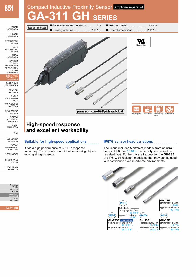
High-speed responseand excellent workability
Suitable for high-speed applicationsIt has a high performance of 3.3 kHz response frequency. These sensors are ideal for sensing objects moving at high speeds.
IP67G sensor head variationsThe lineup includes 5 different models, from an ultra-compact 2.8 mm 0.110 in diameter type to a spatter-resistant type. Furthermore, all except for the GH-2SE are IP67G oil-resistant models so that they can be used with confidence even in adverse environments.
GH-8SE Sensing range: 0 to 4.0 mm 0 to 0.157 in Appearance: ø8 mm ø0.315 in
GH-2SE Sensing range: 0 to 1.2 mm 0 to 0.047 in Appearance: ø2.8 mm ø0.110 in
GH-F8SE Sensing range: 0 to 4.0 mm 0 to 0.157 in Appearance: ø8 mm ø0.315 in
Spatter-resistant GH-5SE Sensing range: 0 to 2.4 mm 0 to 0.094 in Appearance: ø5.4 mm ø0.213 in
GH-3SE Sensing range: 0 to 1.8 mm 0 to 0.071 in Appearance: ø3.8 mm ø0.150 in
IP67G
IP67G
IP67G IP67G
Recognition
Self-diagnosis
diagnosis
Oil resistant Metal embeddingpossible
With adjuster
Compact Inductive Proximity Sensor Amplifier-separated
GA-311 GH SERIES General terms and conditions ............. F-3 Selection guide ............................. P.781~
Glossary of terms........................ P.1576~ General precautions ................... P.1579~
panasonic.net/id/pidsx/global
Compact Inductive Proximity Sensor GA-311 GH SERIES 852
FIBERSENSORS
LASERSENSORS
PHOTOELECTRICSENSORS
MICROPHOTOELECTRICSENSORS
AREASENSORS
SAFETY LIGHT CURTAINS /SAFETY COMPONENTSPRESSURE / FLOWSENSORSINDUCTIVEPROXIMITYSENSORS
PARTICULARUSE SENSORS
SENSOROPTIONS
SIMPLEWIRE-SAVINGUNITS
WIRE-SAVING SYSTEMS
MEASUREMENTSENSORS
STATIC CONTROL DEVICES
LASERMARKERS
PLC
HUMAN MACHINE INTERFACES
ENERGY MANAGEMENT SOLUTIONS
FA COMPONENTS
MACHINE VISION SYSTEMS
UV CURING SYSTEMS
Selection GuideAmplifier Built-inAmplifier-separatedOther Products
GA-311/GH
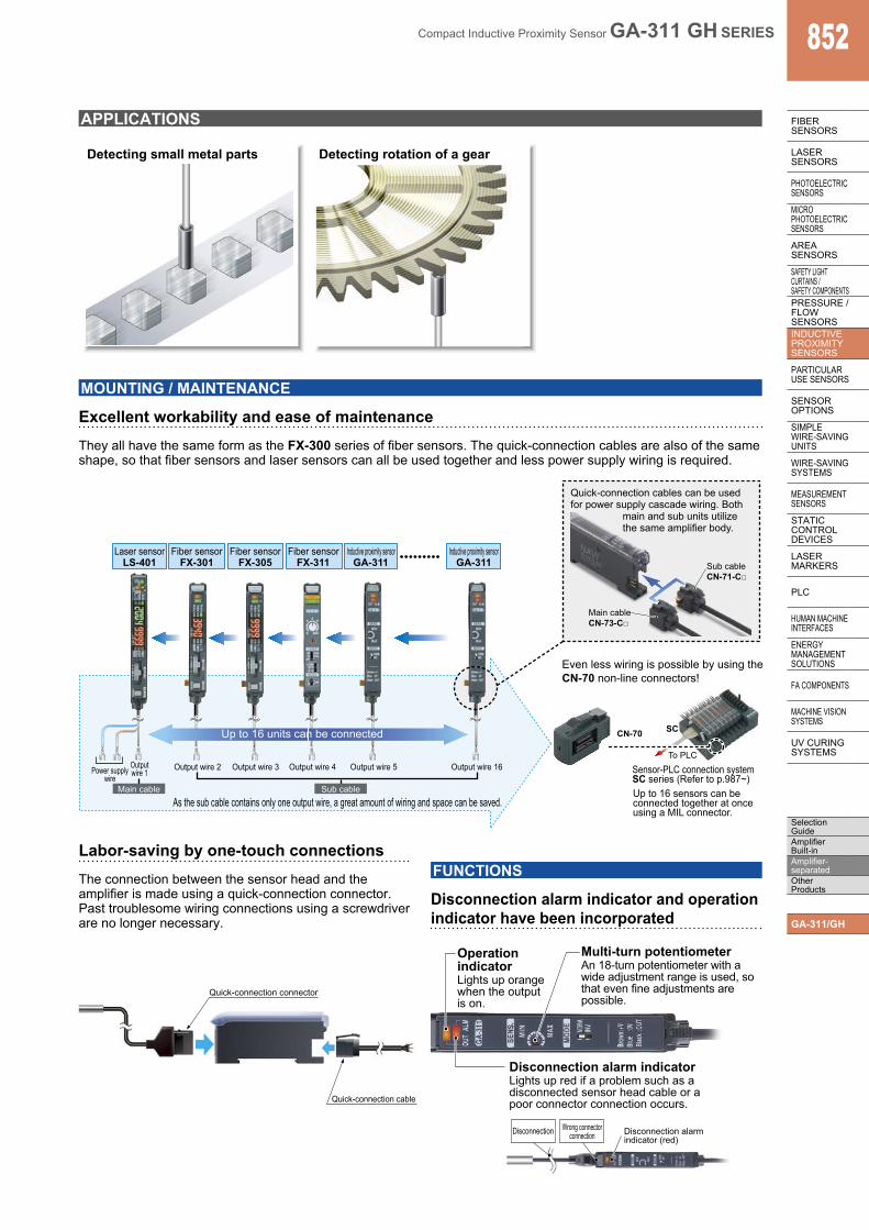
APPLICATIONS
Detecting small metal parts Detecting rotation of a gear
MOUNTING / MAINTENANCE
Excellent workability and ease of maintenanceThey all have the same form as the FX-300 series of fiber sensors. The quick-connection cables are also of the same shape, so that fiber sensors and laser sensors can all be used together and less power supply wiring is required.
Sub cable CN-71-C
Main cable CN-73-C
CN-70
To PLC
Power supply wire
As the sub cable contains only one output wire, a great amount of wiring and space can be saved.
Output wire 1
Output wire 2 Output wire 3 Output wire 4 Output wire 5
Main cable Sub cable
Output wire 16
Up to 16 units can be connected SC
Sensor-PLC connection systemSC series (Refer to p.987~)Up to 16 sensors can be connected together at once using a MIL connector.
Quick-connection cables can be used for power supply cascade wiring. Both
main and sub units utilize the same amplifier body.
Even less wiring is possible by using the CN-70 non-line connectors!
Fiber sensor FX-301
Laser sensor LS-401
Fiber sensor FX-305
Fiber sensor FX-311
Inductive proximity sensor GA-311
Inductive proximity sensorGA-311
FUNCTIONS
Disconnection alarm indicator and operation indicator have been incorporated
Labor-saving by one-touch connectionsThe connection between the sensor head and the amplifier is made using a quick-connection connector. Past troublesome wiring connections using a screwdriver are no longer necessary.
Quick-connection connector
Quick-connection cable
Multi-turn potentiometer An 18-turn potentiometer with a wide adjustment range is used, so that even fine adjustments are possible.
Operation indicator Lights up orange when the output is on.
Disconnection alarm indicatorLights up red if a problem such as adisconnected sensor head cable or apoor connector connection occurs.
Disconnection alarmindicator (red)
Disconnection Wrong connectorconnection
Compact Inductive Proximity Sensor GA-311 GH SERIES853
FIBERSENSORS
LASERSENSORS
PHOTO-ELECTRICSENSORS
MICROPHOTO-
ELECTRICSENSORS
AREASENSORS
SAFETY LIGHT CURTAINS /
SAFETY COMPONENTSPRESSURE /
FLOWSENSORS
INDUCTIVEPROXIMITY
SENSORS
PARTICULARUSE
SENSORS
SENSOROPTIONS
SIMPLEWIRE-SAVING
UNITS
WIRE-SAVING SYSTEMS
MEASURE-MENT
SENSORS
STATIC CONTROL DEVICES
LASERMARKERS
PLC
HUMAN MACHINE
INTERFACES
ENERGY MANAGEMENT
SOLUTIONS
FA COMPONENTS
MACHINE VISION
SYSTEMS
UV CURING
SYSTEMS
Selection Guide
Amplifier Built-in
Amplifier-separated
Other Products
GA-311/GH
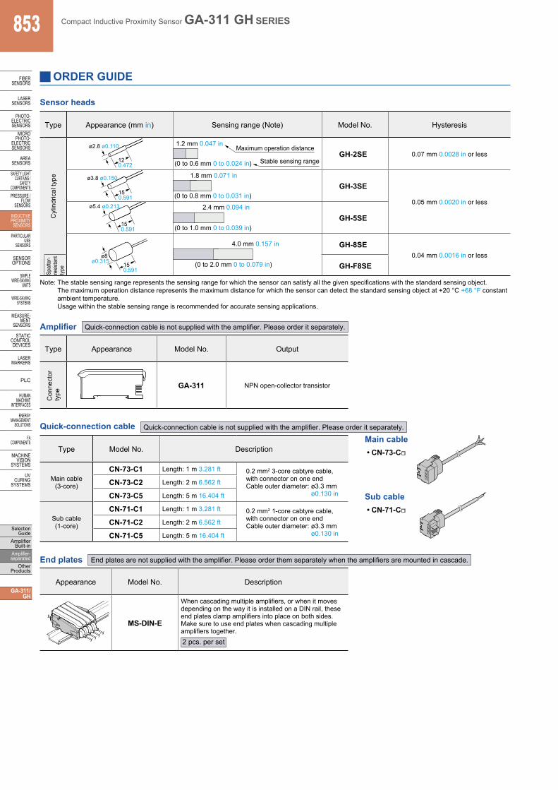
Sensor heads
Note: The stable sensing range represents the sensing range for which the sensor can satisfy all the given specifications with the standard sensing object. The maximum operation distance represents the maximum distance for which the sensor can detect the standard sensing object at +20 °C +68 °F constant ambient temperature. Usage within the stable sensing range is recommended for accurate sensing applications.
Amplifier Quick-connection cable is not supplied with the amplifier. Please order it separately.
Type Appearance Model No. Output
Con
nect
orty
pe
GA-311 NPN open-collector transistor
Quick-connection cable Quick-connection cable is not supplied with the amplifier. Please order it separately.
Type Model No. Description
Main cable(3-core)
CN-73-C1 Length: 1 m 3.281 ft 0.2 mm2 3-core cabtyre cable, with connector on one endCable outer diameter: ø3.3 mm
ø0.130 inCN-73-C2 Length: 2 m 6.562 ft
CN-73-C5 Length: 5 m 16.404 ft
Sub cable(1-core)
CN-71-C1 Length: 1 m 3.281 ft 0.2 mm2 1-core cabtyre cable, with connector on one endCable outer diameter: ø3.3 mm
ø0.130 inCN-71-C2 Length: 2 m 6.562 ft
CN-71-C5 Length: 5 m 16.404 ft
Main cable
Sub cable• CN-71-C
• CN-73-C
End plates End plates are not supplied with the amplifier. Please order them separately when the amplifiers are mounted in cascade.
Appearance Model No. Description
MS-DIN-E
When cascading multiple amplifiers, or when it moves depending on the way it is installed on a DIN rail, these end plates clamp amplifiers into place on both sides. Make sure to use end plates when cascading multiple amplifiers together.2 pcs. per set
Type Appearance (mm in) Sensing range (Note) Model No. Hysteresis
Cyl
indr
ical
type
120.472
ø2.8 ø0.110
(0 to 0.6 mm 0 to 0.024 in)
1.2 mm 0.047 inMaximum operation distance
Stable sensing rangeGH-2SE 0.07 mm 0.0028 in or less
150.591
ø3.8 ø0.150 1.8 mm 0.071 in
(0 to 0.8 mm 0 to 0.031 in)GH-3SE
0.05 mm 0.0020 in or less
150.591
ø5.4 ø0.213
(0 to 1.0 mm 0 to 0.039 in)
2.4 mm 0.094 in
GH-5SE
ø8 ø0.315
150.591
4.0 mm 0.157 in
(0 to 2.0 mm 0 to 0.079 in)
GH-8SE0.04 mm 0.0016 in or less
Spat
ter-
resis
tant
ty
pe GH-F8SE
ORDER GUIDE
Compact Inductive Proximity Sensor GA-311 GH SERIES 854
FIBERSENSORS
LASERSENSORS
PHOTO-ELECTRICSENSORSMICROPHOTO-ELECTRICSENSORS
AREASENSORS
SAFETY LIGHT CURTAINS /SAFETY COMPONENTSPRESSURE / FLOWSENSORS
INDUCTIVEPROXIMITYSENSORS
PARTICULARUSE SENSORS
SENSOROPTIONS
SIMPLEWIRE-SAVINGUNITS
WIRE-SAVING SYSTEMS
MEASURE-MENTSENSORS
STATIC CONTROL DEVICES
LASERMARKERS
PLC
HUMAN MACHINE INTERFACES
ENERGY MANAGEMENT SOLUTIONS
FA COMPONENTS
MACHINE VISION SYSTEMS
UV CURING SYSTEMS
Selection GuideAmplifier Built-inAmplifier-separatedOther Products
GA-311/GH
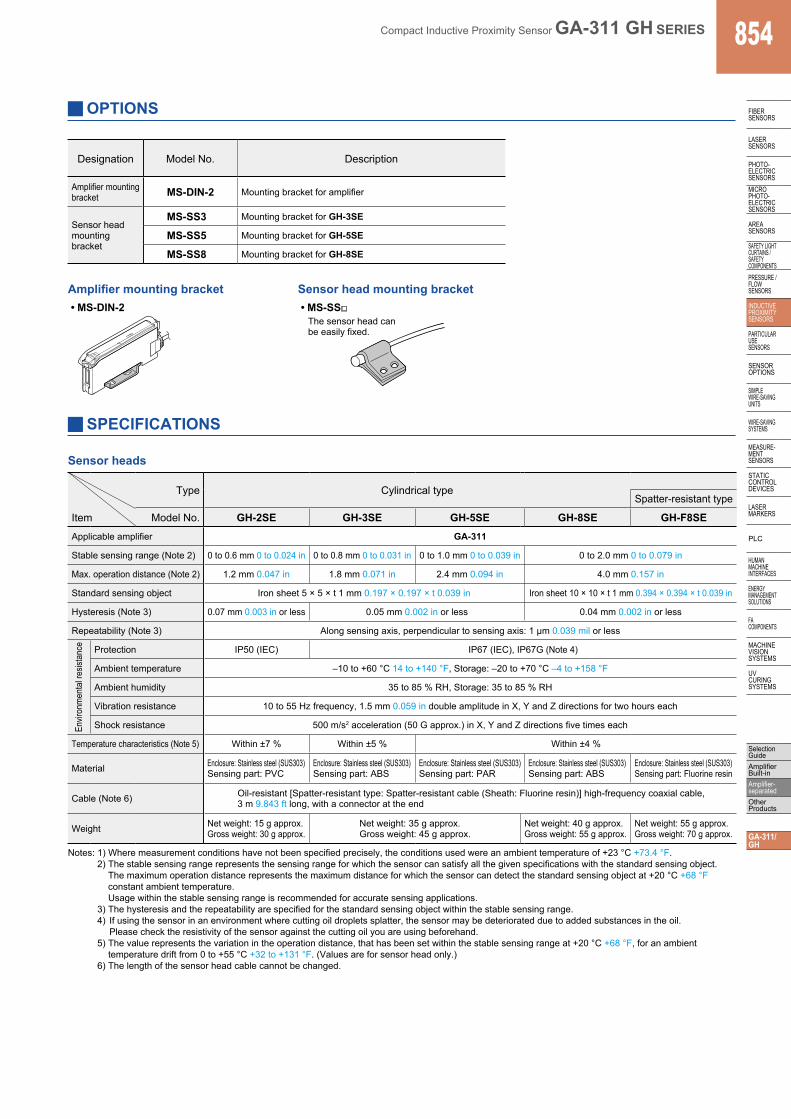
OPTIONS
Notes: 1) Where measurement conditions have not been specified precisely, the conditions used were an ambient temperature of +23 °C +73.4 °F.2) The stable sensing range represents the sensing range for which the sensor can satisfy all the given specifications with the standard sensing object.
The maximum operation distance represents the maximum distance for which the sensor can detect the standard sensing object at +20 °C +68 °F constant ambient temperature. Usage within the stable sensing range is recommended for accurate sensing applications.
3) The hysteresis and the repeatability are specified for the standard sensing object within the stable sensing range.4) If using the sensor in an environment where cutting oil droplets splatter, the sensor may be deteriorated due to added substances in the oil.
Please check the resistivity of the sensor against the cutting oil you are using beforehand.5) The value represents the variation in the operation distance, that has been set within the stable sensing range at +20 °C +68 °F, for an ambient
temperature drift from 0 to +55 °C +32 to +131 °F. (Values are for sensor head only.)6) The length of the sensor head cable cannot be changed.
SPECIFICATIONS
Sensor heads
Type Cylindrical typeSpatter-resistant type
Item Model No. GH-2SE GH-3SE GH-5SE GH-8SE GH-F8SEApplicable amplifier GA-311
Stable sensing range (Note 2) 0 to 0.6 mm 0 to 0.024 in 0 to 0.8 mm 0 to 0.031 in 0 to 1.0 mm 0 to 0.039 in 0 to 2.0 mm 0 to 0.079 in
Max. operation distance (Note 2) 1.2 mm 0.047 in 1.8 mm 0.071 in 2.4 mm 0.094 in 4.0 mm 0.157 in
Standard sensing object Iron sheet 5 × 5 × t 1 mm 0.197 × 0.197 × t 0.039 in Iron sheet 10 × 10 × t 1 mm 0.394 × 0.394 × t 0.039 in
Hysteresis (Note 3) 0.07 mm 0.003 in or less 0.05 mm 0.002 in or less 0.04 mm 0.002 in or less
Repeatability (Note 3) Along sensing axis, perpendicular to sensing axis: 1 µm 0.039 mil or less
Envir
onm
enta
l res
istan
ce Protection IP50 (IEC) IP67 (IEC), IP67G (Note 4)
Ambient temperature –10 to +60 °C 14 to +140 °F, Storage: –20 to +70 °C –4 to +158 °F
Ambient humidity 35 to 85 % RH, Storage: 35 to 85 % RH
Vibration resistance 10 to 55 Hz frequency, 1.5 mm 0.059 in double amplitude in X, Y and Z directions for two hours each
Shock resistance 500 m/s2 acceleration (50 G approx.) in X, Y and Z directions five times each
Temperature characteristics (Note 5) Within ±7 % Within ±5 % Within ±4 %
Material Enclosure: Stainless steel (SUS303)Sensing part: PVC
Enclosure: Stainless steel (SUS303)Sensing part: ABS
Enclosure: Stainless steel (SUS303)Sensing part: PAR
Enclosure: Stainless steel (SUS303)Sensing part: ABS
Enclosure: Stainless steel (SUS303)Sensing part: Fluorine resin
Cable (Note 6) Oil-resistant [Spatter-resistant type: Spatter-resistant cable (Sheath: Fluorine resin)] high-frequency coaxial cable, 3 m 9.843 ft long, with a connector at the end
Weight Net weight: 15 g approx. Gross weight: 30 g approx.
Net weight: 35 g approx.Gross weight: 45 g approx.
Net weight: 40 g approx. Gross weight: 55 g approx.
Net weight: 55 g approx. Gross weight: 70 g approx.
Designation Model No. Description
Amplifier mounting bracket MS-DIN-2 Mounting bracket for amplifier
Sensor head mounting bracket
MS-SS3 Mounting bracket for GH-3SE
MS-SS5 Mounting bracket for GH-5SE
MS-SS8 Mounting bracket for GH-8SE
Amplifier mounting bracket• MS-DIN-2
Sensor head mounting bracket• MS-SS
The sensor head canbe easily fixed.
Compact Inductive Proximity Sensor GA-311 GH SERIES855
FIBERSENSORS
LASERSENSORS
PHOTO-ELECTRICSENSORS
MICROPHOTO-
ELECTRICSENSORS
AREASENSORS
SAFETY LIGHT CURTAINS /
SAFETY COMPONENTSPRESSURE /
FLOWSENSORS
INDUCTIVEPROXIMITY
SENSORS
PARTICULARUSE
SENSORS
SENSOROPTIONS
SIMPLEWIRE-SAVING
UNITS
WIRE-SAVING SYSTEMS
MEASURE-MENT
SENSORS
STATIC CONTROL DEVICES
LASERMARKERS
PLC
HUMAN MACHINE
INTERFACES
ENERGY MANAGEMENT
SOLUTIONS
FA COMPONENTS
MACHINE VISION
SYSTEMS
UV CURING
SYSTEMS
Selection Guide
Amplifier Built-in
Amplifier-separated
Other Products
GA-311/GH
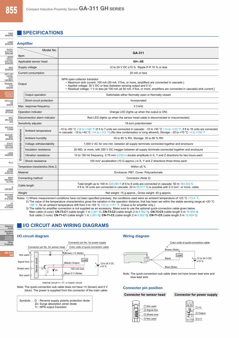
SPECIFICATIONS
Amplifier
Notes: 1) Where measurement conditions have not been specified precisely, the conditions used were an ambient temperature of +23 °C +73.4 °F.2) The value of the temperature characteristics gives the variation in the operation distance, that has been set within the stable sensing range at +20 °C
+68 °F, for an ambient temperature drift from 0 to +55 °C +32 to +131 °F. (Value is for amplifier only.)3) The cable for amplifier connection is not supplied as an accessory. Make sure to use the optional quick-connection cable given below.
Main cable (3-core): CN-73-C1 (cable length 1 m 3.281 ft), CN-73-C2 (cable length 2 m 6.562 ft), CN-73-C5 (cable length 5 m 16.404 ft) Sub cable (1-core): CN-71-C1 (cable length 1 m 3.281 ft), CN-71-C2 (cable length 2 m 6.562 ft), CN-71-C5 (cable length 5 m 16.404 ft)
Model No.GA-311
Item
Applicable sensor head GH-SE
Supply voltage 12 to 24 V DC ±10 % Ripple P-P 10 % or less
Current consumption 25 mA or less
OutputNPN open-collector transistor
• Maximum sink current: 100 mA (50 mA, if five, or more, amplifiers are connected in cascade.)• Applied voltage: 30 V DC or less (between sensing output and 0 V)• Residual voltage: 1 V or less [at 100 mA (at 50 mA, if five, or more, amplifiers are connected in cascade) sink current.]
Output operation Switchable either Normally open or Normally closed
Short-circuit protection Incorporated
Max. response frequency 3.3 kHz
Operation indicator Orange LED (lights up when the output is ON)
Disconnection alarm indicator Red LED (lights up when the sensor head cable is disconnected or misconnected)
Sensitivity adjuster 18-turn potentiometer
Env
ironm
enta
l res
ista
nce Ambient temperature –10 to +60 °C +14 to +140 °F (If 4 to 7 units are connected in cascade: –10 to +50 °C +14 to +122 °F, if 8 to 16 units are connected
in cascade: –10 to +45 °C +14 to +113 °F) (No dew condensation or icing allowed), Storage: –20 to +70 °C –4 to +158 °F
Ambient humidity 35 to 85 % RH, Storage: 35 to 85 % RH
Voltage withstandability 1,000 V AC for one min. between all supply terminals connected together and enclosure
Insulation resistance 20 MΩ, or more, with 250 V DC megger between all supply terminals connected together and enclosure
Vibration resistance 10 to 150 Hz frequency, 0.75 mm 0.030 in double amplitude in X, Y and Z directions for two hours each
Shock resistance 100 m/s2 acceleration (10 G approx.) in X, Y and Z directions three times each
Temperature characteristics (Note 2) Within ±5 %
Material Enclosure: PBT, Cover: Polycarbonate
Connecting method Connector (Note 3)
Cable length Total length up to 100 m 328.084 ft (if 5 to 8 units are connected in cascade: 50 m 164.042 ft, if 9 to 16 units are connected in cascade: 20 m 65.617 ft) is possible with 0.3 mm2, or more, cable.
Weight Net weight: 15 g approx., Gross weight: 40 g approx.
I/O CIRCUIT AND WIRING DIAGRAMS
I/O circuit diagram Wiring diagram
Note: The quick-connection sub cable does not have +V (brown) and 0 V (blue). The power is supplied from the connector of the main cable.
100 mA max.
(Blue) 0 V (Note)
12 to 24 V DC±10 %
(Brown) +V (Note) Not used
(Black) Output
Color code of quick-connection cable
Users’ circuit Internal circuit
Connector pin No. for power supply
Connector pin No. for sensor head
Tr
D
ZD
Load Signal line
Shield wire
Not used
1 1
4
3
3 2
2
Sen
sor c
ircui
t
– +
12 to 24 V DC±10 %
Brown (Note)
Black
Blue (Note)
Color code of quick-connection cable
Load
– +
Connector pin position
Note: The quick-connection sub cable does not have brown lead wire and blue lead wire.
Not usedSignal line
Not used
Shield wire
1
2
3
4
Connector for sensor head
+V
Output
0 V
1
3
2
Connector for power supply
Symbols … D : Reverse supply polarity protection diodeZD: Surge absorption zener diodeTr : NPN output transistor
Compact Inductive Proximity Sensor GA-311 GH SERIES 856
FIBERSENSORS
LASERSENSORS
PHOTO-ELECTRICSENSORSMICROPHOTO-ELECTRICSENSORS
AREASENSORS
SAFETY LIGHT CURTAINS /SAFETY COMPONENTSPRESSURE / FLOWSENSORS
INDUCTIVEPROXIMITYSENSORS
PARTICULARUSE SENSORS
SENSOROPTIONS
SIMPLEWIRE-SAVINGUNITS
WIRE-SAVING SYSTEMS
MEASURE-MENTSENSORS
STATIC CONTROL DEVICES
LASERMARKERS
PLC
HUMAN MACHINE INTERFACES
ENERGY MANAGEMENT SOLUTIONS
FA COMPONENTS
MACHINE VISION SYSTEMS
UV CURING SYSTEMS
Selection GuideAmplifier Built-inAmplifier-separatedOther Products
GA-311/GH
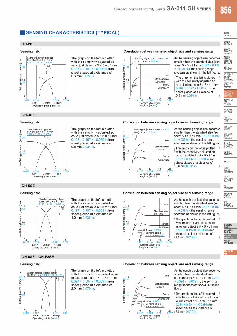
SENSING CHARACTERISTICS (TYPICAL)
GH-2SE
Sensing field
The graph on the left is plotted with the sensitivity adjusted so as to just detect a 5 × 5 × t 1 mm 0.197 × 0.197 × t 0.039 in iron sheet placed at a distance of 0.6 mm 0.024 in.
Correlation between sensing object size and sensing range
As the sensing object size becomes smaller than the standard size (iron sheet 5 × 5 × t 1 mm 0.197 × 0.197 × t 0.039 in), the sensing range shortens as shown in the left figure.
The graph on the left is plotted with the sensitivity adjusted so as to just detect a 5 × 5 × t 1 mm 0.197 × 0.197 × t 0.039 in iron sheet placed at a distance of 0.6 mm 0.024 in.0
0.50.020
10.039
Set
ting
dist
ance
L (m
m in
)
Left RightCenterOperating point ℓ (mm in)
20.079
10.039
0 10.039
20.079
ℓL
Standard sensing object Iron sheet 5 × 5 × t 1 mm0.197 × 0.197 × t 0.039 in
0.50.020
10.039
Sen
sing
rang
e L
(mm
in)
0 50.197
100.394
150.591
200.787
Sensing object side length a (mm in)
t 1 mm t 0.039 inSensing object a × a mm a × a in
L
Iron
BrassAluminum
Stainless steel (SUS304)
GH-3SE
Sensing field
The graph on the left is plotted with the sensitivity adjusted so as to just detect a 5 × 5 × t 1 mm 0.197 × 0.197 × t 0.039 in iron sheet placed at a distance of 0.8 mm 0.031 in.
As the sensing object size becomes smaller than the standard size (iron sheet 5 × 5 × t 1 mm 0.197 × 0.197 × t 0.039 in), the sensing range shortens as shown in the left figure.
Correlation between sensing object size and sensing range
The graph on the left is plotted with the sensitivity adjusted so as to just detect a 5 × 5 × t 1 mm 0.197 × 0.197 × t 0.039 in iron sheet placed at a distance of 0.8 mm 0.031 in.
ℓL
0
0.50.020
10.039
Set
ting
dist
ance
L (m
m in
)
Left RightCenterOperating point ℓ (mm in)
20.079
10.039
0 10.039
20.079
Standard sensing object Iron sheet 5 × 5 × t 1 mm0.197 × 0.197 × t 0.039 in
0.50.020
10.039
Sen
sing
rang
e L
(mm
in)
0 50.197
100.394
150.591
200.787
Sensing object side length a (mm in)
t 1 mm t 0.039 inSensing object a × a mm a × a in
L
Iron
BrassAluminum
Stainless steel (SUS304)
GH-5SE
Sensing field
The graph on the left is plotted with the sensitivity adjusted so as to just detect a 5 × 5 × t 1 mm 0.197 × 0.197 × t 0.039 in iron sheet placed at a distance of 1.0 mm 0.039 in.
As the sensing object size becomes smaller than the standard size (iron sheet 5 × 5 × t 1 mm 0.197 × 0.197 × t 0.039 in), the sensing range shortens as shown in the left figure.
Correlation between sensing object size and sensing range
The graph on the left is plotted with the sensitivity adjusted so as to just detect a 5 × 5 × t 1 mm 0.197 × 0.197 × t 0.039 in iron sheet placed at a distance of 1.0 mm 0.039 in.
ℓL
0
0.50.020
10.039
Set
ting
dist
ance
L (m
m in
)
Left RightCenterOperating point ℓ (mm in)
40.157
20.079
0 20.079
40.157
Standard sensing object Iron sheet 5 × 5 × t 1 mm0.197 × 0.197 × t 0.039 in
L t 1 mm t 0.039 in
0.50.020
10.039
Sen
sing
rang
e L
(mm
in)
0 50.197
100.394
150.591
200.787
Sensing object side length a (mm in)
Sensing object a × a mm a × a in
Iron
BrassAluminum
Stainless steel (SUS304)
GH-8SE GH-F8SE
Sensing field
The graph on the left is plotted with the sensitivity adjusted so as to just detect a 10 × 10 × t 1 mm 0.394 × 0.394 × t 0.039 in iron sheet placed at a distance of 2.0 mm 0.079 in.
As the sensing object size becomes smaller than the standard size (iron sheet 10 × 10 × t 1 mm 0.394 × 0.394 × t 0.039 in), the sensing range shortens as shown in the left figure.
Correlation between sensing object size and sensing range
The graph on the left is plotted with the sensitivity adjusted so as to just detect a 10 × 10 × t 1 mm 0.394 × 0.394 × t 0.039 in iron sheet placed at a distance of 2.0 mm 0.079 in.
ℓL
0
10.039
20.079
Set
ting
dist
ance
L (m
m in
)
Left RightCenterOperating point ℓ (mm in)
100.394
50.197
0 50.197
100.394
Standard sensing object Iron sheet 10 × 10 × t 1 mm 0.394 × 0.394 × t 0.039 in
L
1 0.039
2 0.079
Sen
sing
rang
e L
(mm
in)
0 5 0.197
10 0.394
15 0.591
20 0.787
Sensing object side length a (mm in)
Iron
Brass
Aluminum
Stainless steel (SUS304)
Sensing object a × a mm a × a in
t 1 mm t 0.039 in
Compact Inductive Proximity Sensor GA-311 GH SERIES857
FIBERSENSORS
LASERSENSORS
PHOTO-ELECTRICSENSORS
MICROPHOTO-
ELECTRICSENSORS
AREASENSORS
SAFETY LIGHT CURTAINS /
SAFETY COMPONENTSPRESSURE /
FLOWSENSORS
INDUCTIVEPROXIMITY
SENSORS
PARTICULARUSE
SENSORS
SENSOROPTIONS
SIMPLEWIRE-SAVING
UNITS
WIRE-SAVING SYSTEMS
MEASURE-MENT
SENSORS
STATIC CONTROL DEVICES
LASERMARKERS
PLC
HUMAN MACHINE
INTERFACES
ENERGY MANAGEMENT
SOLUTIONS
FA COMPONENTS
MACHINE VISION
SYSTEMS
UV CURING
SYSTEMS
Selection Guide
Amplifier Built-in
Amplifier-separated
Other Products
GA-311/GH
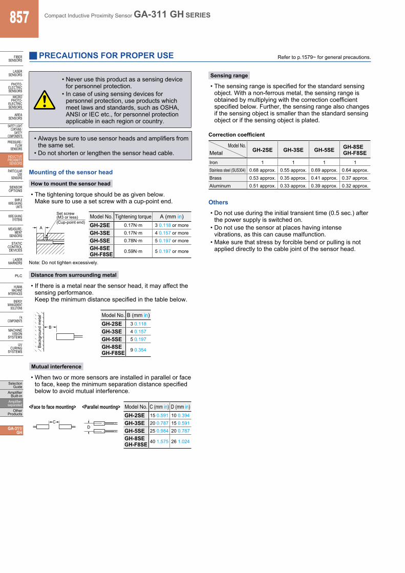
PRECAUTIONS FOR PROPER USE Refer to p.1579~ for general precautions.
Others
• Do not use during the initial transient time (0.5 sec.) after the power supply is switched on.
• Do not use the sensor at places having intense vibrations, as this can cause malfunction.
• Make sure that stress by forcible bend or pulling is not applied directly to the cable joint of the sensor head.
Mounting of the sensor head
How to mount the sensor head
• The tightening torque should be as given below. Make sure to use a set screw with a cup-point end.
Note: Do not tighten excessively.
Sensing range
A
Set screw(M3 or less)(Cup-point end)
Model No. Tightening torque A (mm in)GH-2SE 0.17N·m 3 0.118 or more
GH-3SE 0.17N·m 4 0.157 or more
GH-5SE 0.78N·m 5 0.197 or moreGH-8SEGH-F8SE 0.59N·m 5 0.197 or more
Distance from surrounding metal
• If there is a metal near the sensor head, it may affect the sensing performance. Keep the minimum distance specified in the table below.
B
Bac
kgro
und
met
al Model No. B (mm in)GH-2SE 3 0.118
GH-3SE 4 0.157
GH-5SE 5 0.197GH-8SEGH-F8SE 9 0.354
Mutual interference
• When two or more sensors are installed in parallel or face to face, keep the minimum separation distance specified below to avoid mutual interference.
<Face to face mounting> <Parallel mounting>
CD
Model No. C (mm in) D (mm in)GH-2SE 15 0.591 10 0.394
GH-3SE 20 0.787 15 0.591
GH-5SE 25 0.984 20 0.787GH-8SEGH-F8SE 40 1.575 26 1.024
Correction coefficient
Model No.Metal GH-2SE GH-3SE GH-5SE GH-8SE
GH-F8SEIron 1 1 1 1Stainless steel (SUS304) 0.68 approx. 0.55 approx. 0.69 approx. 0.64 approx.Brass 0.53 approx. 0.35 approx. 0.41 approx. 0.37 approx.Aluminum 0.51 approx. 0.33 approx. 0.39 approx. 0.32 approx.
• Always be sure to use sensor heads and amplifiers from the same set.
• Do not shorten or lengthen the sensor head cable.
• The sensing range is specified for the standard sensing object. With a non-ferrous metal, the sensing range is obtained by multiplying with the correction coefficient specified below. Further, the sensing range also changes if the sensing object is smaller than the standard sensing object or if the sensing object is plated.
• Never use this product as a sensing device for personnel protection.
• In case of using sensing devices for personnel protection, use products which meet laws and standards, such as OSHA, ANSI or IEC etc., for personnel protection applicable in each region or country.
Compact Inductive Proximity Sensor GA-311 GH SERIES 858
FIBERSENSORS
LASERSENSORS
PHOTO-ELECTRICSENSORSMICROPHOTO-ELECTRICSENSORS
AREASENSORS
SAFETY LIGHT CURTAINS /SAFETY COMPONENTSPRESSURE / FLOWSENSORS
INDUCTIVEPROXIMITYSENSORS
PARTICULARUSE SENSORS
SENSOROPTIONS
SIMPLEWIRE-SAVINGUNITS
WIRE-SAVING SYSTEMS
MEASURE-MENTSENSORS
STATIC CONTROL DEVICES
LASERMARKERS
PLC
HUMAN MACHINE INTERFACES
ENERGY MANAGEMENT SOLUTIONS
FA COMPONENTS
MACHINE VISION SYSTEMS
UV CURING SYSTEMS
Selection GuideAmplifier Built-inAmplifier-separatedOther Products
GA-311/GH
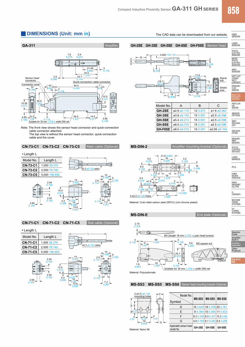
GA-311 Amplifier GH-2SE GH-3SE GH-5SE GH-8SE GH-F8SE Sensor head
Note: The front view shows the sensor head connector and quick-connection cable connector attached. The top view is without the sensor head connector, quick-connection cable and the cover.
80.315
60.236
17.60.693 Signal
line
BA
C 3,000 118.110
Shield wire
( )
18.10.713( )
160.630( )
12.20.480
180.709
Model No. A B CGH-2SE ø2.8 ø0.110 12 0.472 ø1.6 ø0.063
GH-3SE ø3.8 ø0.150 15 0.591 ø2.5 ø0.098GH-5SE ø5.4 ø0.213 15 0.591 ø2.5 ø0.098GH-8SE ø8.0 ø0.315 15 0.591 ø2.5 ø0.098
GH-F8SE ø8.0 ø0.315 15 0.591 ø2.65 ø0.104
CN-73-C1 CN-73-C2 CN-73-C5 Main cable (Optional)
L
2.65 0.104
2.54 0.100
2.54 0.100 0.2
0.008 13.6 0.535
10 0.394
14 0.551
7.2 0.283
3 0.118
2.9 0.114
6 0.236
10 0.394
ø3.3 ø0.130 cable
7 0.276
10.5 0.413
• Length L
Model No. Length LCN-73-C1 1,000 39.370
CN-73-C2 2,000 78.740
CN-73-C5 5,000 196.850
Sub cable (Optional)CN-71-C1 CN-71-C2 CN-71-C5
L
2.65 0.104
2.54 0.100
2.54 0.100 0.2
0.008 13.6 0.535
10 0.394
14 0.551
7.2 0.283
3 0.118
2.9 0.114
6 0.236
10 0.394
ø3.3 ø0.130 cable
7 0.276
10.5 0.413
• Length L
Model No. Length L
CN-71-C1 1,000 39.370
CN-71-C2 2,000 78.740
CN-71-C5 5,000 196.850
MS-DIN-2 Amplifier mounting bracket (Optional)
3.20.126
8.50.335
5.20.205
21.6 0.85016
0.630
5.20.205
3.20.126
50.197
100.394
351.378
271.063
20.079
t 1t 0.039
0.40.016
7.5 0.295 4.2 0.165
20.079ø1.8
ø0.071
2-ø3.2 ø0.126 holes
MS-DIN-E End plate (Optional)
2.75 0.108
4 0.157
3 0.118
M3 (length 18 mm 0.709 in) pan head screws
M3 square nut 5.6 0.220
24.7 0.972
1.6 0.063
32 1.260
60 2.362 15
0.591
3 0.118
Suitable for 35 mm 1.378 in width DIN rail
MS-SS3 MS-SS5 MS-SS8 Sensor head mounting bracket (Optional)
D E
F
G
4 0.157
40.157
80.315
40.157
160.630
2-ø3.5 ø0.138mounting holes Model No.
MS-SS3 MS-SS5 MS-SS8Symbol
D 16 0.630 18 0.709 20 0.787E 9 0.354 10 0.394 11 0.433F 6.3 0.248 8.3 0.327 10.3 0.406G 4.9 0.193 6.1 0.240 6.5 0.256
Applicable sensor head model No. GH-3SE GH-5SE GH-8SE
DIMENSIONS (Unit: mm in) The CAD data can be downloaded from our website.
Material: Cold rolled carbon steel (SPCC) (Uni-chrome plated)
Material: Polycarbonate
Material: Nylon 66