Embed Size (px)
Citation preview
AC
-D
C
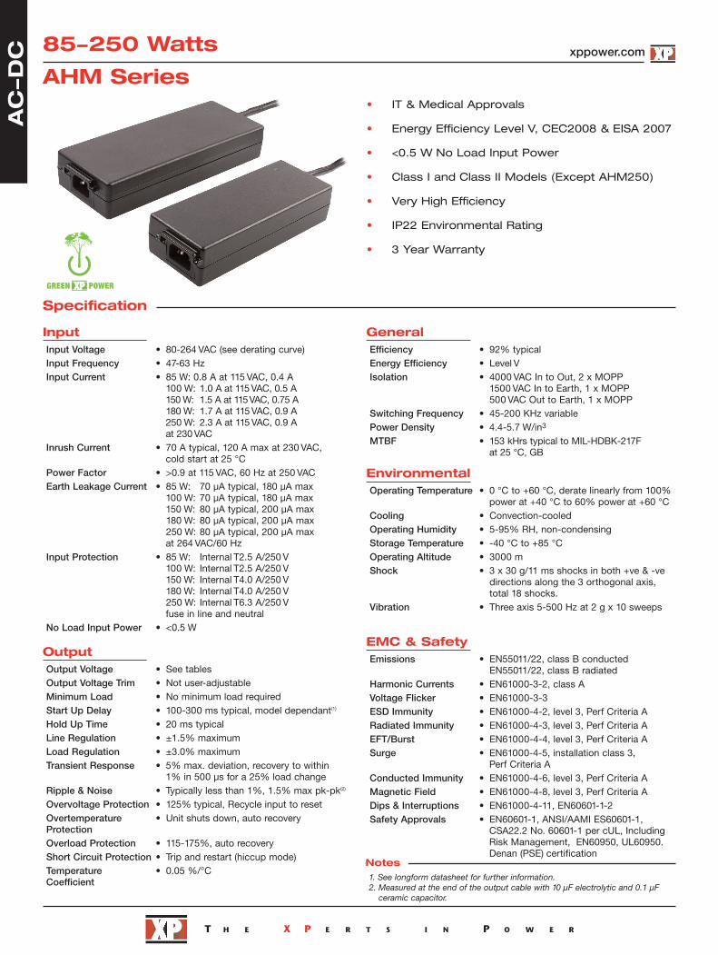
Specification
85-250 Watts
• IT & Medical Approvals
• Energy Efficiency Level V, CEC2008 & EISA 2007
• <0.5 W No Load Input Power
• Class I and Class II Models (Except AHM250)
• Very High Efficiency
• IP22 Environmental Rating
• 3 Year Warranty
AHM Series
InputInput Voltage • 80-264 VAC (see derating curve)Input Frequency • 47-63 HzInput Current • 85 W: 0.8 A at 115 VAC, 0.4 A
100 W: 1.0 A at 115 VAC, 0.5 A150 W: 1.5 A at 115 VAC, 0.75 A180 W: 1.7 A at 115 VAC, 0.9 A250 W: 2.3 A at 115 VAC, 0.9 A at 230 VAC
Inrush Current • 70 A typical, 120 A max at 230 VAC, cold start at 25 °C
Power Factor • >0.9 at 115 VAC, 60 Hz at 250 VACEarth Leakage Current • 85 W: 70 µA typical, 180 µA max
100 W: 70 µA typical, 180 µA max 150 W: 80 µA typical, 200 µA max180 W: 80 µA typical, 200 µA max250 W: 80 µA typical, 200 µA max at 264 VAC/60 Hz
Input Protection • 85 W: Internal T2.5 A/250 V100 W: Internal T2.5 A/250 V150 W: Internal T4.0 A/250 V 180 W: Internal T4.0 A/250 V250 W: Internal T6.3 A/250 V fuse in line and neutral
No Load Input Power • <0.5 W
OutputOutput Voltage • See tablesOutput Voltage Trim • Not user-adjustableMinimum Load • No minimum load requiredStart Up Delay • 100-300 ms typical, model dependant(1)
Hold Up Time • 20 ms typicalLine Regulation • ±1.5% maximumLoad Regulation • ±3.0% maximumTransient Response • 5% max. deviation, recovery to within
1% in 500 µs for a 25% load change Ripple & Noise • Typically less than 1%, 1.5% max pk-pk(2)
Overvoltage Protection • 125% typical, Recycle input to resetOvertemperature • Unit shuts down, auto recoveryProtectionOverload Protection • 115-175%, auto recoveryShort Circuit Protection • Trip and restart (hiccup mode)Temperature • 0.05 %/°CCoefficient
xppower.com
GeneralEfficiency • 92% typicalEnergy Efficiency • Level VIsolation • 4000 VAC In to Out, 2 x MOPP
1500 VAC In to Earth, 1 x MOPP500 VAC Out to Earth, 1 x MOPP
Switching Frequency • 45-200 KHz variablePower Density • 4.4-5.7 W/in3
MTBF • 153 kHrs typical to MIL-HDBK-217F at 25 °C, GB
EnvironmentalOperating Temperature • 0 °C to +60 °C, derate linearly from 100%
power at +40 °C to 60% power at +60 °CCooling • Convection-cooledOperating Humidity • 5-95% RH, non-condensingStorage Temperature • -40 °C to +85 °COperating Altitude • 3000 mShock • 3 x 30 g/11 ms shocks in both +ve & -ve
directions along the 3 orthogonal axis, total 18 shocks.
Vibration • Three axis 5-500 Hz at 2 g x 10 sweeps
EMC & SafetyEmissions • EN55011/22, class B conducted
EN55011/22, class B radiated Harmonic Currents • EN61000-3-2, class AVoltage Flicker • EN61000-3-3ESD Immunity • EN61000-4-2, level 3, Perf Criteria ARadiated Immunity • EN61000-4-3, level 3, Perf Criteria AEFT/Burst • EN61000-4-4, level 3, Perf Criteria ASurge • EN61000-4-5, installation class 3,
Perf Criteria AConducted Immunity • EN61000-4-6, level 3, Perf Criteria AMagnetic Field • EN61000-4-8, level 3, Perf Criteria ADips & Interruptions • EN61000-4-11, EN60601-1-2Safety Approvals • EN60601-1, ANSI/AAMI ES60601-1,
CSA22.2 No. 60601-1 per cUL, IncludingRisk Management, EN60950, UL60950.Denan (PSE) certification
1. See longform datasheet for further information.2. Measured at the end of the output cable with 10 µF electrolytic and 0.1 µF
ceramic capacitor.
Notes
Optional Input Connector Retention (-A)
1.40 (35.7)
AC
-D
C
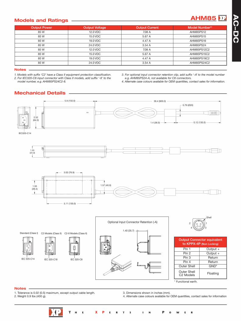
AHM85Models and Ratings
Mechanical Details
Notes
Notes
Output Power Output Voltage Output Current Model Number(1)
85 W 12.0 VDC 7.08 A AHM85PS12
85 W 15.0 VDC 5.67 A AHM85PS15
85 W 19.0 VDC 4.47 A AHM85PS19
85 W 24.0 VDC 3.54 A AHM85PS24
85 W 12.0 VDC 7.08 A AHM85PS12C2
85 W 15.0 VDC 5.67 A AHM85PS15C2
85 W 19.0 VDC 4.47 A AHM85PS19C2
85 W 24.0 VDC 3.54 A AHM85PS24C2
1. Tolerance is 0.02 (0.5) maximum, except output cable length.2. Weight 0.9 lbs (400 g).
3. Dimensions shown in inches (mm). 4. Alternate case colours available for OEM quantities, contact sales for information
Output Connector equivalent to KPPX-4P (Non Locking)
Pin 1 Output +Pin 2 Output +Pin 3 ReturnPin 4 Return
Outer Shell GND*
Outer ShellC2 Models Floating
0.79 (Ø20)
5.12 (130.0)1.4 (36.0)
36.4 (900.0)5.9 (150.0)
IEC320-C14
2.52(64.0)
1.45(37.0)
3.02 (76.9)
1.57 (40.0)
5.11 (130.0)
1.55(39.4)
12
4 3
IEC 320-C14
Shell
IEC 320-C18 IEC 320-C8
C2 Models (Class II) C2-8 Models (Class II)Standard (Class I)
1. Models with suffix ‘C2’ have a Class II equipment protection classification.2. For IEC320-C8 input connector with Class II models, add suffix ‘-8’ to the
model number, e.g. AHM85PS24C2-8.
3. For optional input connector retention clip, add suffix ‘-A’ to the model numbere.g. AHM85PS24-A, not available for C8 connectors.
4. Alternate case colours available for OEM quantities, contact sales for information.
* Functional earth.

IEC 320-C14 IEC 320-C18 IEC 320-C8
C2 Models (Class II) C2-8 Models (Class II)Standard (Class I)
AC
-D
C AHM100Models and Ratings
Mechanical Details
Notes
Notes
Output Power Output Voltage Output Current Model Number(1)
100 W 12.0 VDC 8.33 A AHM100PS12
100 W 15.0 VDC 6.67 A AHM100PS15
100 W 19.0 VDC 5.26 A AHM100PS19
100 W 24.0 VDC 4.16 A AHM100PS24
100 W 48.0 VDC 2.08 A AHM100PS48
100 W 12.0 VDC 8.33 A AHM100PS12C2
100 W 15.0 VDC 6.67 A AHM100PS15C2
100 W 19.0 VDC 5.26 A AHM100PS19C2
100 W 24.0 VDC 4.16 A AHM100PS24C2
100 W 48.0 VDC 2.08 A AHM100PS48C2
1. Tolerance is 0.02 (0.5) maximum, except output cable length.2. Weight 1.1 lbs (500 g).
3. Dimensions shown in inches (mm).
Output Connector equivalent to KPPX-4P (Non Locking)
Pin 1 Output +Pin 2 Output +Pin 3 ReturnPin 4 Return
Outer Shell GND*
Outer ShellC2 Models Floating
Optional Input Connector Retention (-A)
1.40 (35.7)
1. Models with suffix ‘C2’ have a class II equipment protection classification.2. For IEC320-C8 input connector with class II models, add suffix ‘-8’ to the model
number, e.g. AHM100PS24C2-8.
3. For optional input connector retention clip, add suffix ‘-A’ to the model numbere.g. AHM100PS24-A, not available for C8 connectors.
4. Alternate case colours available for OEM quantities, contact sales for information.
12
4 3
Shell
0.79 (Ø20)
5.12 (130.0)1.4 (36.0)
36.4 (900.0)6.29 (160.0)0.2 (5.0)
2.52(64.0)
1.45(37.0)
3.02 (76.9)
1.57 (40.0)
5.11 (130.0)
1.55(39.4)
* Functional earth.
IEC 320-C14 IEC 320-C18 IEC 320-C8
C2 Models (Class II) C2-8 Models (Class II)Standard (Class I)
AC
-D
C
Output Connector equivalent to KPPX-4P (Non Locking)
Pin 1 Output +Pin 2 Output +Pin 3 ReturnPin 4 Return
Outer Shell GND*
Outer ShellC2 Models Floating
Optional Input Connector Retention (-A)
1.40 (35.7)
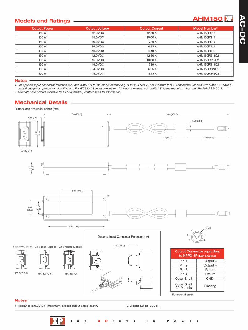
AHM150Models and Ratings
Mechanical Details
Notes
Notes
Dimensions shown in inches (mm).
Output Power Output Voltage Output Current Model Number(1)
150 W 12.0 VDC 12.50 A AHM150PS12
150 W 15.0 VDC 10.00 A AHM150PS15
150 W 19.0 VDC 7.89 A AHM150PS19
150 W 24.0 VDC 6.25 A AHM150PS24
150 W 48.0 VDC 3.13 A AHM150PS48
150 W 12.0 VDC 12.50 A AHM150PS12C2
150 W 15.0 VDC 10.00 A AHM150PS15C2
150 W 19.0 VDC 7.89 A AHM150PS19C2
150 W 24.0 VDC 6.25 A AHM150PS24C2
150 W 48.0 VDC 3.13 A AHM150PS48C2
1. Tolerance is 0.02 (0.5) maximum, except output cable length. 2. Weight 1.3 lbs (600 g).
1.45(37.0)
3.94 (100.3)
6.8 (173.0)
1.58(40.30)
2.02(51.5)
0.79 (Ø20)
5.12 (130.0)1.4 (36.0)
36.4 (900.0)7.8 (200.0)
0.19 (4.9)
IEC320-C14
3.15(80.0)
1. For optional input connector retention clip, add suffix ‘-A’ to the model number e.g. AHM150PS24-A, not available for C8 connectors. Models with suffix ‘C2’ have aclass II equipment protection classification. For IEC320-C8 input connector with class II models, add suffix ‘-8’ to the model number, e.g. AHM150PS24C2-8.
2. Alternate case colours available for OEM quantities, contact sales for information.
12
4 3
Shell
* Functional earth.

AC
-D
C
Mechanical Details
Notes1. For optional input connector retention clip, add suffix ‘-A’ to the model number e.g. AHM180PS24-A, not available for C8 connectors. Models with suffix ‘C2’ have aclass II equipment protection classification. For IEC320-C8 input connector with class II models, add suffix ‘-8’ to the model number, e.g. AHM180PS24C2-8.
2. Alternate case colours available for OEM quantities, contact sales for information.
0.193 (4.9)
3.15(80.0)
1.61(41.0)
2.02(51.5) 1.58
(40.3)
7.87 (200.0) 35.43 (900.0)
0.79 (Ø20.0)
5.12 (130.0)1.41 (36.0)
3.94 (100.3)
6.81 (173.0)
1. Dimensions shown in inches (mm). Tolerance is 0.02 (0.5) maximum,except output cable length.
2. Weight 1.4 lbs (620 g)
Notes
Dimensions shown in inches (mm).
Output Power Output Voltage Output Current Model Number165 W 12.0 VDC 13.75 A AHM180PS12
180 W 15.0 VDC 12.00 A AHM180PS15
180 W 19.0 VDC 9.47 A AHM180PS19
180 W 24.0 VDC 7.50 A AHM180PS24
180 W 48.0 VDC 3.75 A AHM180PS48
165 W 12.0 VDC 13.75 A AHM180PS12C2
180 W 15.0 VDC 12.00 A AHM180PS15C2
180 W 19.0 VDC 9.47 A AHM180PS19C2
180 W 24.0 VDC 7.50 A AHM180PS24C2
180 W 48.0 VDC 3.75 A AHM180PS48C2
AHM180Models and Ratings
Shell
134
2
Optional Input Connector Retention (-A)
1.40 (35.7)
* Functional earth.
IEC 320-C14 IEC 320-C18 IEC 320-C8
C2 Models (Class II) C2-8 Models (Class II)Standard (Class I)Output Connector equivalent to KPPX-4P (Non Locking)
Pin 1 Output +Pin 2 Output +Pin 3 ReturnPin 4 Return
Outer Shell GND*
Outer ShellC2 Models Floating

18-Sept-17
Mechanical Details
Derating Curve
Notes1. For optional input connector retention clip, add suffix ‘-A’ to the model number e.g. AHM250PS24T-A.2. For 6 pin DIN connector, remove ‘T’ from the end of the model number e.g. AHM250PS24 (DIN connector for medical applications only).
IEC 320-C14
IEC 320-C14
8.8 (223.0)35.43 (900.0)
0.79 (Ø 20.0)
1.417 (36.0)
8.58 (218.0)
Optional 6 pin DIN connector shown(for medical applications only)
Standard Molex 6 pin Connector
0.2 (5.0)
1.457 (37.0)
0.063 (1.60)
Shell
7.41 (188.40)
2.37 (60.20)1.97 (50.20)
5.12 (130.20)
0.79 (Ø 20.0)
4.134 (105.0)1.417 (36.0)
1
2
3
6
4
5
3.484(88.50)
12
3
645
1. Dimensions shown in inches (mm). Tolerance is 0.02(0.5) maximum, except output cable length.
2. Weight 2.2 lbs (1000 g).
Notes
Dimensions shown in inches (mm).
Output Power Output Voltage Output Current Model Number(2)
210 W 12.0 VDC 17.50 A AHM250PS12T
220 W 15.0 VDC 14.66 A AHM250PS15T
240 W 19.0 VDC 12.63 A AHM250PS19T
250 W 24.0 VDC 10.41 A AHM250PS24T
250 W 48.0 VDC 5.21 A AHM250PS48T
40
50
80
60
70
90
100
80 85 90 100 110 240 250 264
AHM85,100,150 & 180 Models
AHM250 Models
Out
put
Pow
er (%
)
AC
-D
C
AHM250Models and Ratings
Optional Input Connector Retention (-A)
1.40 (35.7)
* Functional earth.
OUTPUT CONNECTOR
Pin No. Molex PartNo.: 50-36-1672
DIN PartNo.: DIN45322
Pin 1 Return Output +Pin 2 Return ReturnPin 3 Return ReturnPin 4 Output + ReturnPin 5 Output + Output +Pin 6 Ouput + Ouput +
Outer Shell GND*

![[XLS]navy-training-transformation2.wikispaces.com · Web view0 15 15 85 85 100 100 5 85 100 0.3 1 0.35 0.35 1 85 85 85 85 85 85 85 85 85 85 85 85 85 85 85 85 85 85 85 85 15 15 5 11.5](https://img.pdfslide.us/doc/110x75/5adf226a7f8b9a6e5c8bbbe3/xlsnavy-training-view0-15-15-85-85-100-100-5-85-100-03-1-035-035-1-85-85-85.jpg)