Embed Size (px)
Citation preview
A LaymanA Layman’’s Guide to HARTs Guide to HART®®
Communications with Communications with FIELDVUEFIELDVUE®® InstrumentsInstruments
Jeff VonAhnenRick OsbornFIELDVUE Technical SupportEmerson Process ManagementFisher Valve DivisionMarshalltown, Iowa
Page 2
PresentersPresenters
Jeff VonAhnenFIELDVUE Technical Support
Rick OsbornFIELDVUE Technical Support
Page 3
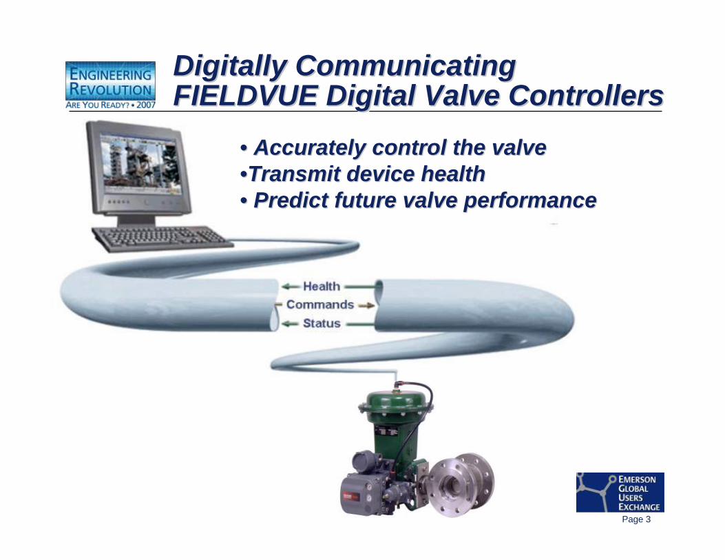
Digitally Communicating FIELDVUE Digital Valve ControllersDigitally Communicating Digitally Communicating FIELDVUE Digital Valve ControllersFIELDVUE Digital Valve Controllers
•• Accurately control the valveAccurately control the valve••Transmit device healthTransmit device health•• Predict future valve performancePredict future valve performance
Page 4
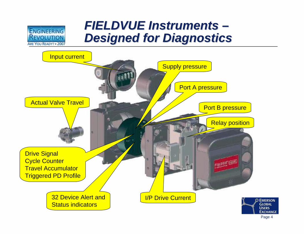
FIELDVUE Instruments –Designed for DiagnosticsFIELDVUE Instruments FIELDVUE Instruments ––Designed for DiagnosticsDesigned for Diagnostics
Actual Valve Travel
Input current
I/P Drive Current
Relay position
Port B pressure
Port A pressure
Supply pressure
32 Device Alert andStatus indicators
Drive SignalCycle CounterTravel AccumulatorTriggered PD Profile
Page 5
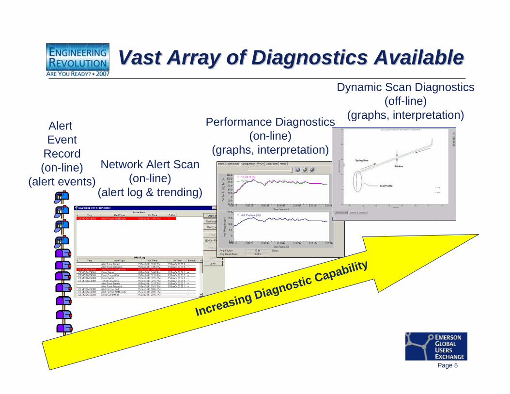
Vast Array of Diagnostics AvailableVast Array of Diagnostics AvailableVast Array of Diagnostics Available
Increasing Diagnostic Capability
Alert Event
Record(on-line)
(alert events)Network Alert Scan
(on-line)(alert log & trending)
Performance Diagnostics(on-line)
(graphs, interpretation)
Dynamic Scan Diagnostics(off-line)
(graphs, interpretation)
Page 6
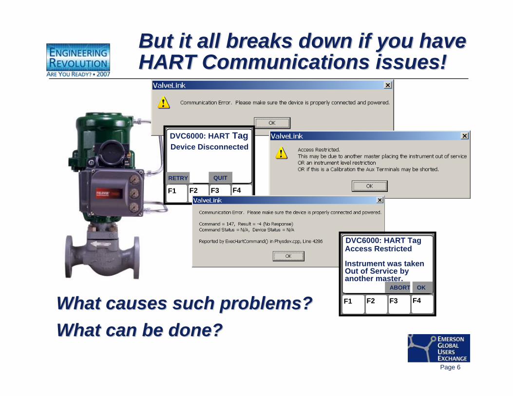
But it all breaks down if you have HART Communications issues!But it all breaks down if you have But it all breaks down if you have HART Communications issues!HART Communications issues!
F1 F2 F3 F4
DVC6000: HART TagDevice Disconnected
RETRY QUIT
What causes such problems?What causes such problems?What can be done?What can be done?
F1 F2 F3 F4
DVC6000: HART TagAccess Restricted
Instrument was takenOut of Service byanother master.
ABORT OK
Page 7
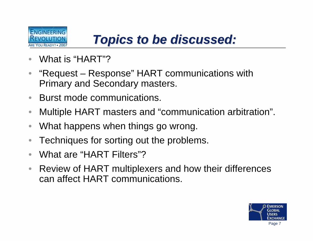
Topics to be discussed:Topics to be discussed:Topics to be discussed:• What is “HART”?• “Request – Response” HART communications with
Primary and Secondary masters.• Burst mode communications.• Multiple HART masters and “communication arbitration”.• What happens when things go wrong.• Techniques for sorting out the problems.• What are “HART Filters”?• Review of HART multiplexers and how their differences
can affect HART communications.
Page 8
So, what is So, what is ““HARTHART””??
Page 9
According to the HART®
Communication Foundation Website:According to the HARTAccording to the HART®®
Communication Foundation Website:Communication Foundation Website:HART:
• is a master-slave field communications protocol • was developed in the late 1980's to facilitate communication with Smart
field devices. • is an acronym for “Highway Addressable Remote Transducer”.• makes use of the Bell 202 Frequency Shift Keying (FSK) standard to
superimpose digital communication signals at a low level on top of the 4-20mA, enabling two-way field communication to take place and makes it possible for additional information beyond just the normal process variable to be communicated to/from a smart field instrument.
• communicates at 1200 bps without interrupting the 4-20mA signal• allows a host application (master) to get two or more digital updates per
second from a field device. • due to the phase continuous digital FSK signal is phase continuous,
creates no interference with the 4-20mA signal.

Page 10
Overload! Overload!Overload! Overload!Overload! Overload!
OK, let’s slow it down a bit …

Page 11
HART HART ““Physical LayerPhysical Layer””
-- the electrical signalsthe electrical signals
Page 12
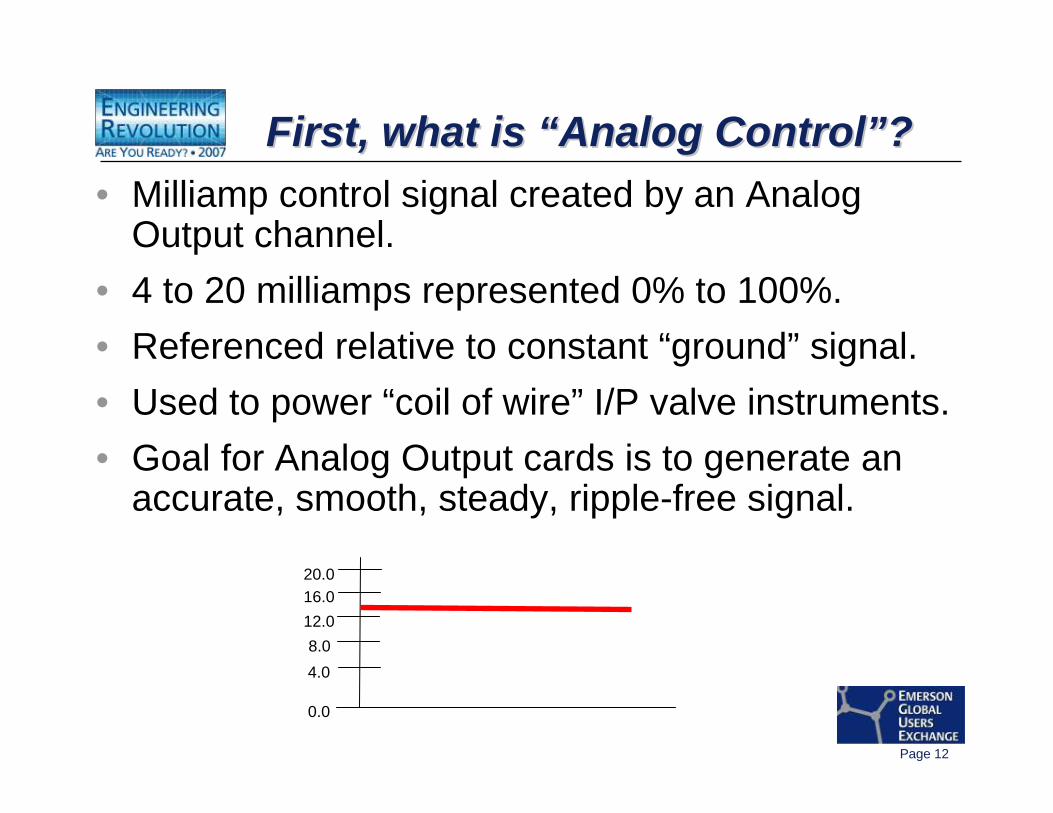
First, what is “Analog Control”?First, what is First, what is ““Analog ControlAnalog Control””??• Milliamp control signal created by an Analog
Output channel.• 4 to 20 milliamps represented 0% to 100%.• Referenced relative to constant “ground” signal.• Used to power “coil of wire” I/P valve instruments.• Goal for Analog Output cards is to generate an
accurate, smooth, steady, ripple-free signal.
4.08.0
12.016.020.0
0.0
Page 13
What is “HART” communication?What is What is ““HARTHART”” communication?communication?
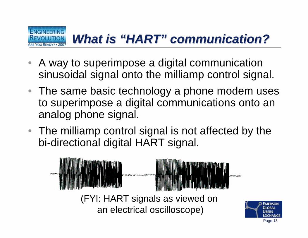
• A way to superimpose a digital communication sinusoidal signal onto the milliamp control signal.
• The same basic technology a phone modem uses to superimpose a digital communications onto an analog phone signal.
• The milliamp control signal is not affected by the bi-directional digital HART signal.
(FYI: HART signals as viewed on an electrical oscilloscope)
Page 14
What is “HART” communication?What is What is ““HARTHART”” communication?communication?
• A different waveform for a transmitter on an Analog Input channel compared to a digital valve controller on an Analog Output channel.
• Depends on what the “1000 pound gorilla” is for each kind of channel.
Page 15
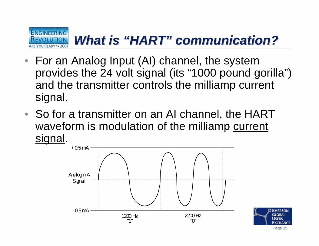
What is “HART” communication?What is What is ““HARTHART”” communication?communication?• For an Analog Input (AI) channel, the system
provides the 24 volt signal (its “1000 pound gorilla”) and the transmitter controls the milliamp current signal.
• So for a transmitter on an AI channel, the HART waveform is modulation of the milliamp current signal.
Analog mASignal
2200 Hz1200 Hz"1" "0"
+ 0.5 mA
- 0.5 mA
Page 16
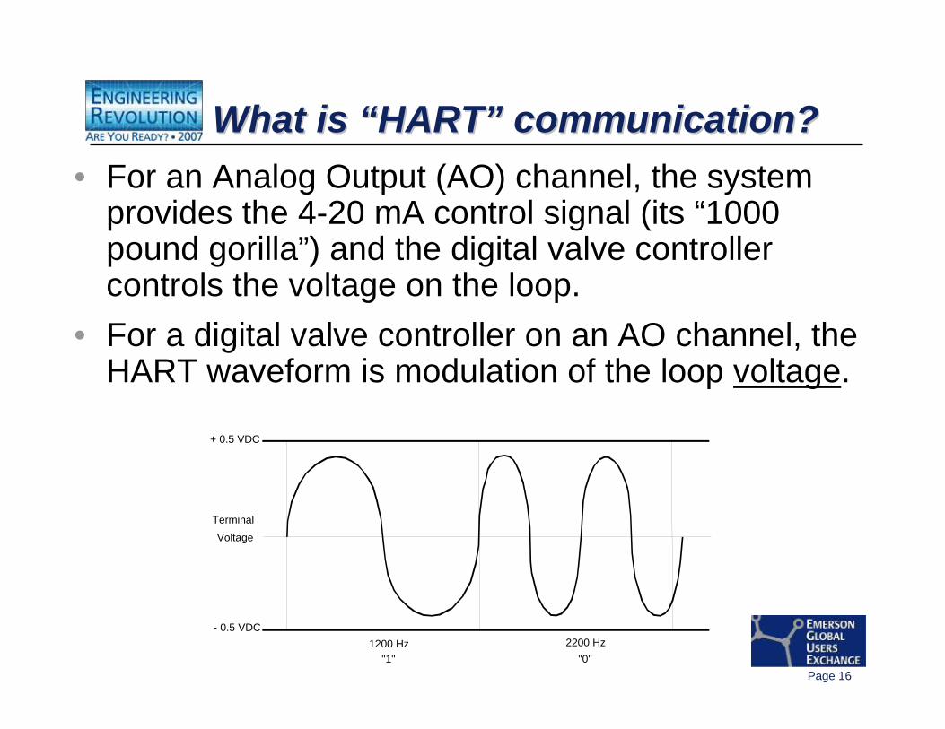
What is “HART” communication?What is What is ““HARTHART”” communication?communication?• For an Analog Output (AO) channel, the system
provides the 4-20 mA control signal (its “1000 pound gorilla”) and the digital valve controller controls the voltage on the loop.
• For a digital valve controller on an AO channel, the HART waveform is modulation of the loop voltage.
TerminalVoltage
2200 Hz1200 Hz"1" "0"
+ 0.5 VDC
- 0.5 VDC
Page 17
HART CommunicationsHART Communications
-- Possible Physical Layer Possible Physical Layer problemsproblems
Page 18
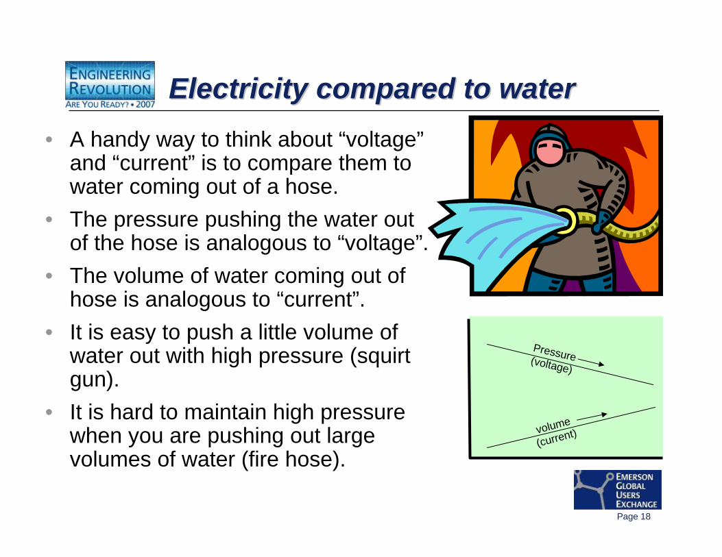
Electricity compared to waterElectricity compared to waterElectricity compared to water• A handy way to think about “voltage”
and “current” is to compare them to water coming out of a hose.
• The pressure pushing the water out of the hose is analogous to “voltage”.
• The volume of water coming out of hose is analogous to “current”.
• It is easy to push a little volume of water out with high pressure (squirt gun).
• It is hard to maintain high pressure when you are pushing out large volumes of water (fire hose).
volume
(current)
Pressure(voltage)
Page 19
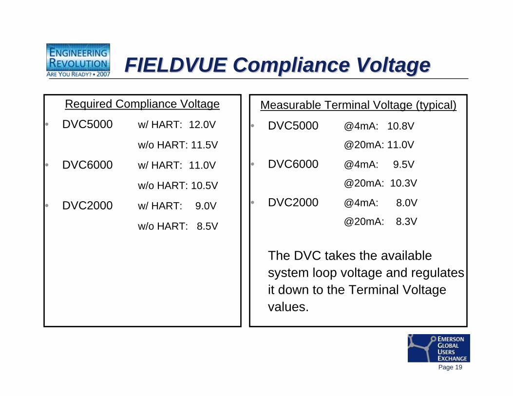
FIELDVUE Compliance VoltageFIELDVUE Compliance VoltageFIELDVUE Compliance Voltage
Required Compliance Voltage
• DVC5000 w/ HART: 12.0V
w/o HART: 11.5V
• DVC6000 w/ HART: 11.0V
w/o HART: 10.5V
• DVC2000 w/ HART: 9.0V
w/o HART: 8.5V
Measurable Terminal Voltage (typical)
• DVC5000 @4mA: 10.8V
@20mA: 11.0V
• DVC6000 @4mA: 9.5V
@20mA: 10.3V
• DVC2000 @4mA: 8.0V
@20mA: 8.3V
The DVC takes the available system loop voltage and regulates it down to the Terminal Voltage values.
Page 20
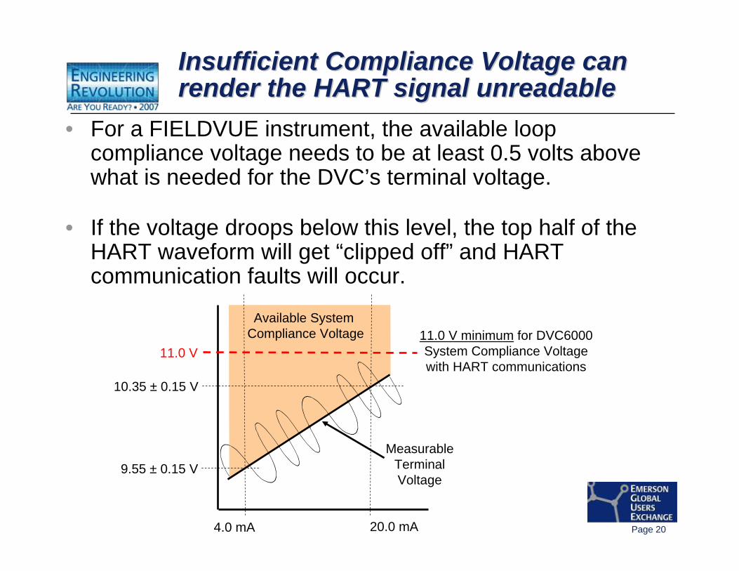
Insufficient Compliance Voltage can render the HART signal unreadableInsufficient Compliance Voltage can Insufficient Compliance Voltage can render the HART signal unreadablerender the HART signal unreadable
4.0 mA 20.0 mA
9.55 ± 0.15 V
10.35 ± 0.15 V
11.0 V minimum for DVC6000System Compliance Voltagewith HART communications
Available System Compliance Voltage
MeasurableTerminalVoltage
11.0 V
• For a FIELDVUE instrument, the available loop compliance voltage needs to be at least 0.5 volts above what is needed for the DVC’s terminal voltage.
• If the voltage droops below this level, the top half of the HART waveform will get “clipped off” and HART communication faults will occur.

Page 21
Electrical noise can mess upthe HART signals
Electrical noise can mess upElectrical noise can mess upthe HART signalsthe HART signals
This includes:– High strength Electro-Magnetic Interference
(EMI) (“walkie talkie”, arc welding, etc).
– Poor electrical wiring, shielding, and grounding practices.
Page 22
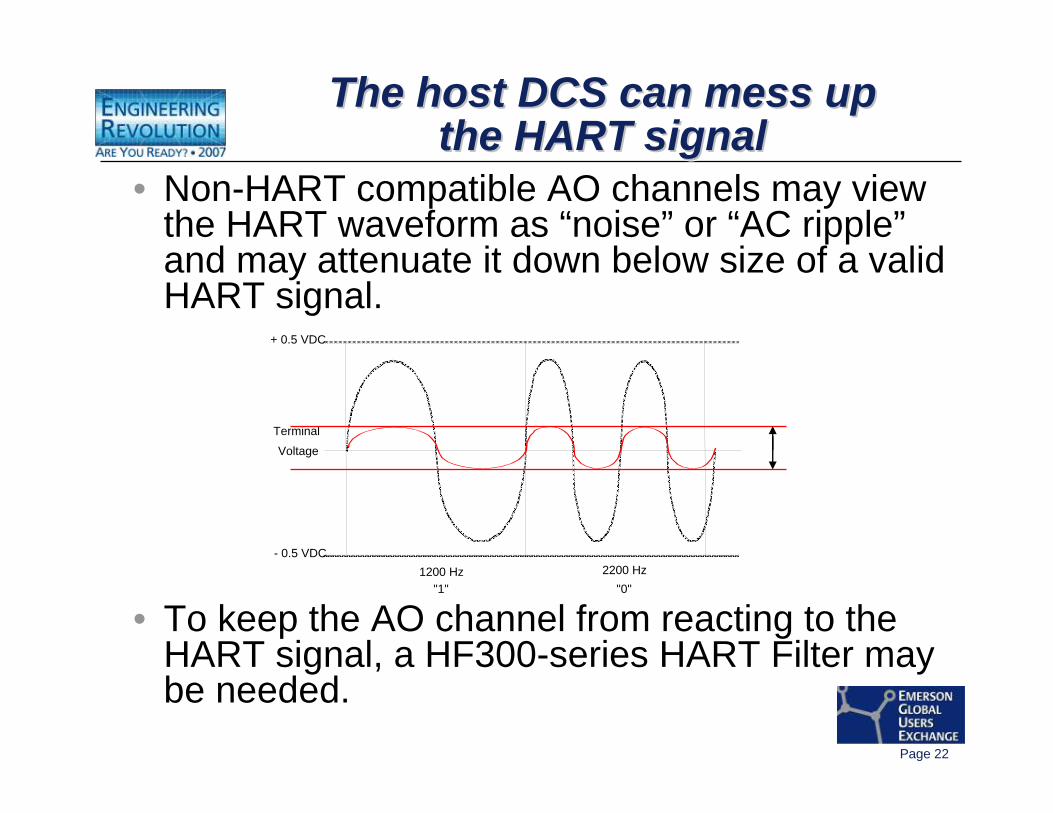
• Non-HART compatible AO channels may view the HART waveform as “noise” or “AC ripple”and may attenuate it down below size of a valid HART signal.
• To keep the AO channel from reacting to the HART signal, a HF300-series HART Filter may be needed.
The host DCS can mess upthe HART signal
The host DCS can mess upThe host DCS can mess upthe HART signalthe HART signal
Terminal
Voltage
2200 Hz1200 Hz"1" "0"
+ 0.5 VDC
- 0.5 VDC
Page 23
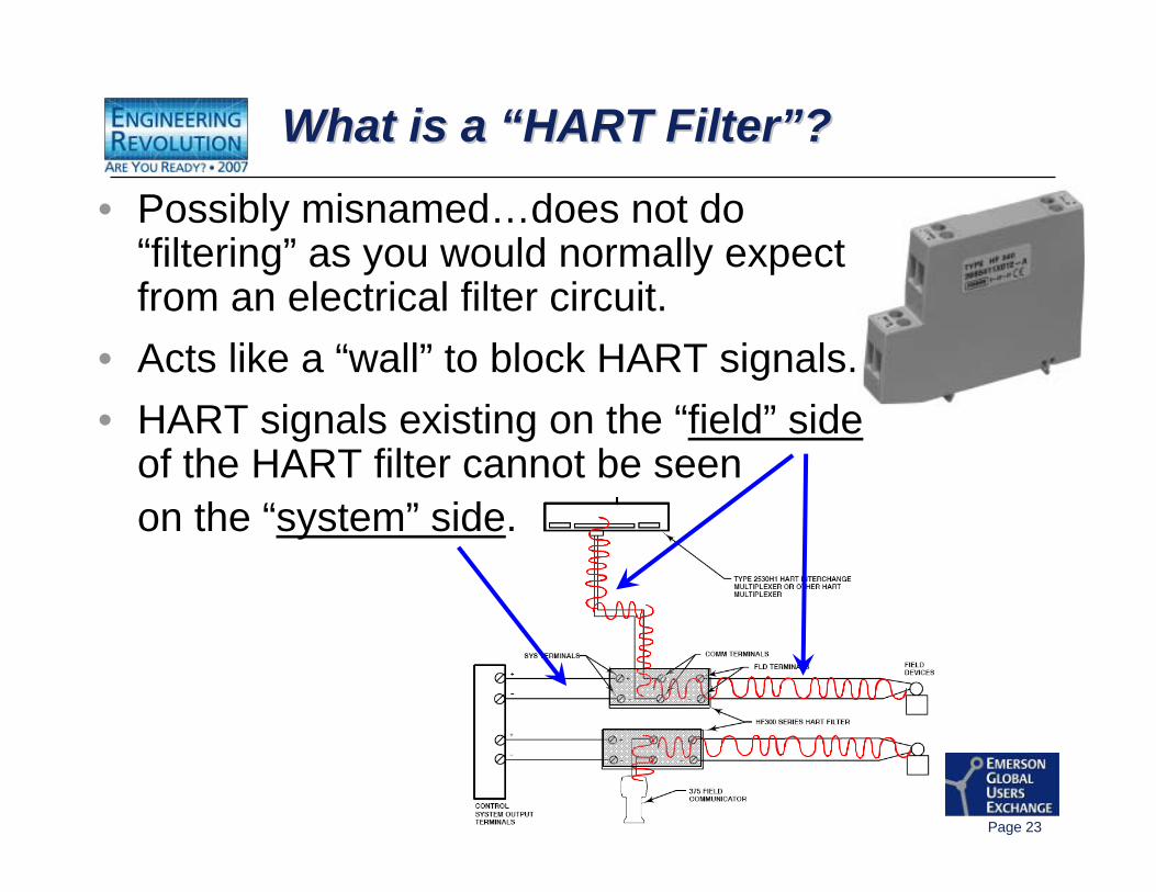
What is a “HART Filter”?What is a What is a ““HART FilterHART Filter””??
• Possibly misnamed…does not do “filtering” as you would normally expect from an electrical filter circuit.
• Acts like a “wall” to block HART signals.• HART signals existing on the “field” side
of the HART filter cannot be seen on the “system” side.
Page 24
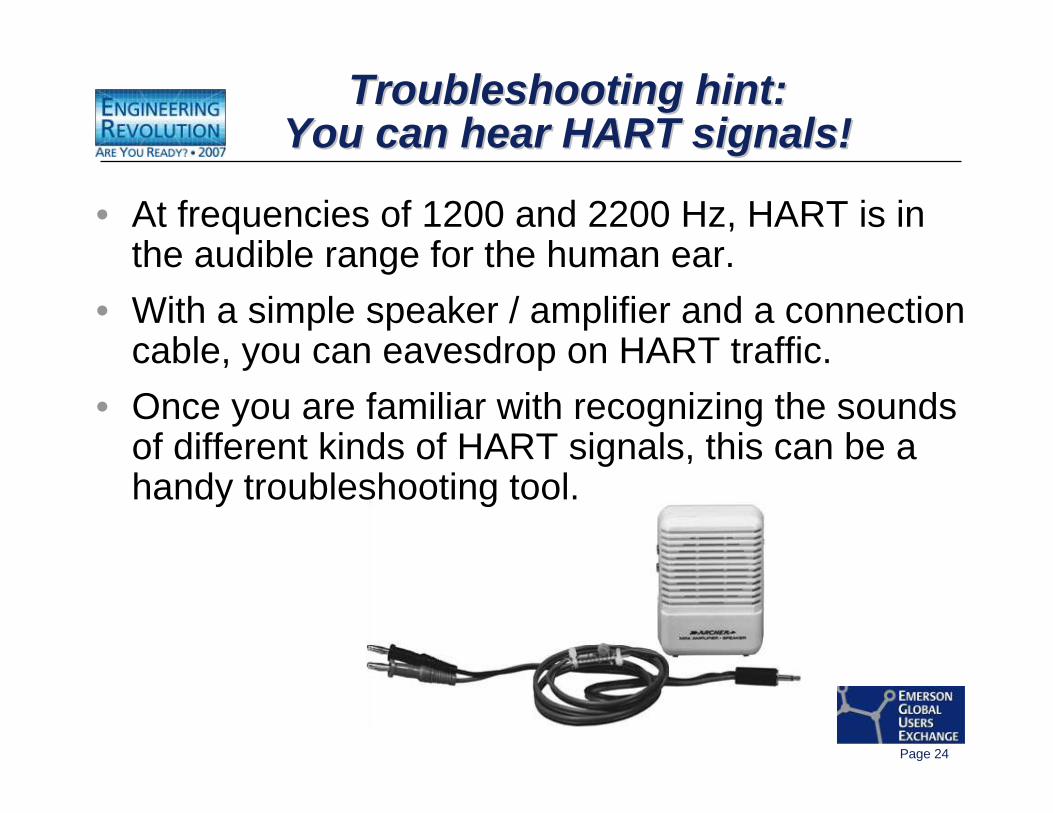
Troubleshooting hint:You can hear HART signals!
Troubleshooting hint:Troubleshooting hint:You can hear HART signals!You can hear HART signals!
• At frequencies of 1200 and 2200 Hz, HART is in the audible range for the human ear.
• With a simple speaker / amplifier and a connection cable, you can eavesdrop on HART traffic.
• Once you are familiar with recognizing the sounds of different kinds of HART signals, this can be a handy troubleshooting tool.
Page 25
HART CommunicationsHART Communications
-- Master Communication DevicesMaster Communication Devices
Page 26
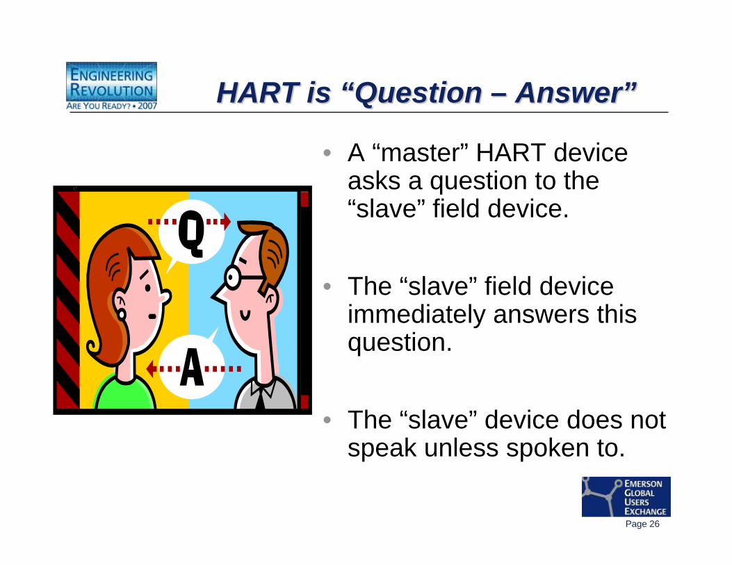
HART is “Question – Answer”HART is HART is ““Question Question –– AnswerAnswer””
• A “master” HART device asks a question to the “slave” field device.
• The “slave” field device immediately answers this question.
• The “slave” device does not speak unless spoken to.
Page 27
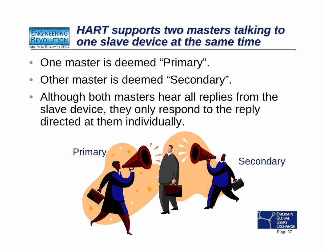
HART supports two masters talking to one slave device at the same timeHART supports two masters talking to HART supports two masters talking to one slave device at the same timeone slave device at the same time
• One master is deemed “Primary”.• Other master is deemed “Secondary”.• Although both masters hear all replies from the
slave device, they only respond to the reply directed at them individually.
PrimarySecondary
Page 28
HART supports two masters talking to one slave device at the same timeHART supports two masters talking to HART supports two masters talking to one slave device at the same timeone slave device at the same time
Rules of HART communication “arbitration”:• Only one HART master of each gender allowed.• Both masters are very polite and courteous.• They alternate taking turns talking to the one
slave device.• No interrupting while the other master is talking!
Page 29
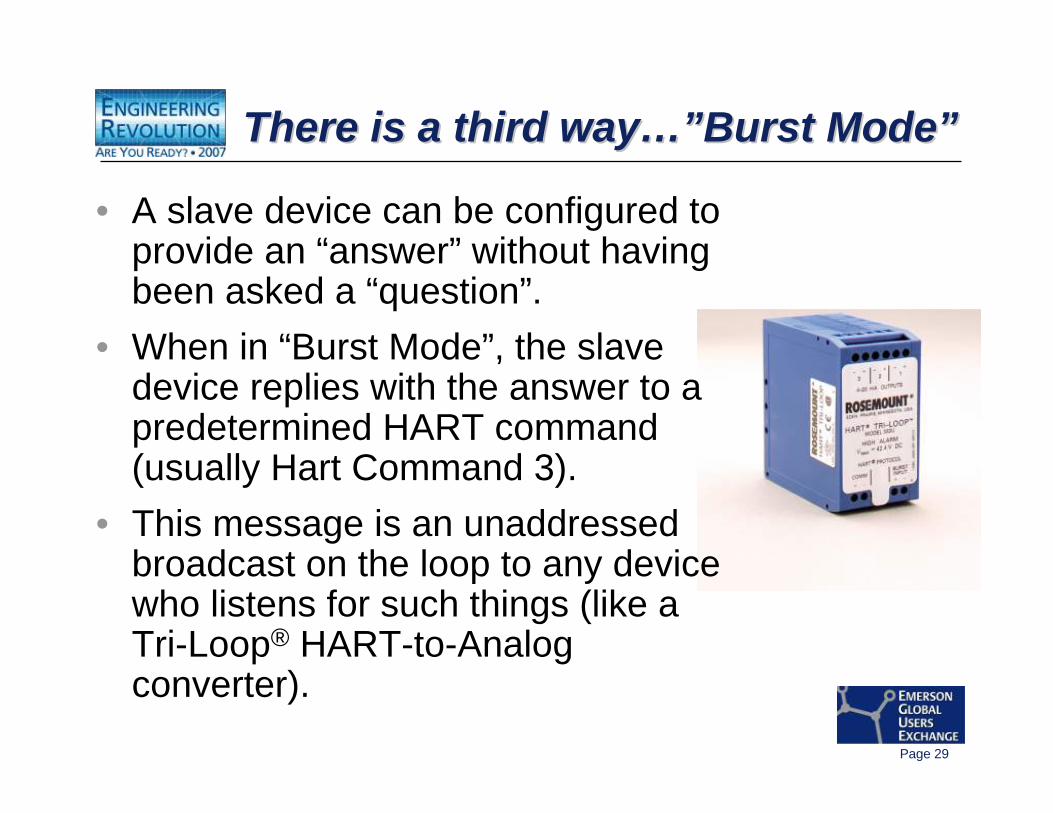
There is a third way…”Burst Mode”There is a third wayThere is a third way…”…”Burst ModeBurst Mode””
• A slave device can be configured to provide an “answer” without having been asked a “question”.
• When in “Burst Mode”, the slave device replies with the answer to a predetermined HART command (usually Hart Command 3).
• This message is an unaddressed broadcast on the loop to any device who listens for such things (like a Tri-Loop® HART-to-Analog converter).
Page 30
Burst Mode CommunicationsBurst Mode CommunicationsBurst Mode Communications
• Other masters ignore “Burst Mode” messages, but must arbitrate around them.
• Burst Mode communications get interspersed between Primary and Secondary master communications.
• The slave device now becomes responsible for its portion of the HART communication arbitration with the other master devices.
Page 31
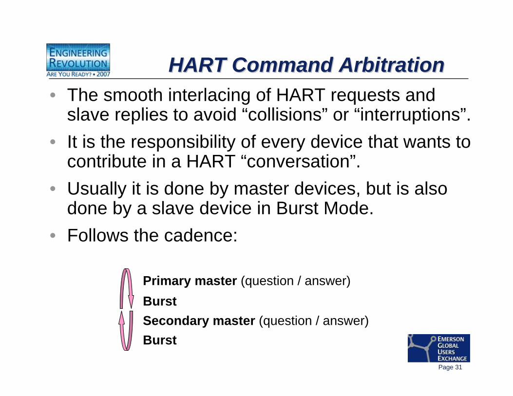
HART Command ArbitrationHART Command ArbitrationHART Command Arbitration• The smooth interlacing of HART requests and
slave replies to avoid “collisions” or “interruptions”.• It is the responsibility of every device that wants to
contribute in a HART “conversation”.• Usually it is done by master devices, but is also
done by a slave device in Burst Mode.• Follows the cadence:
Primary master (question / answer)Burst Secondary master (question / answer)Burst
Page 32
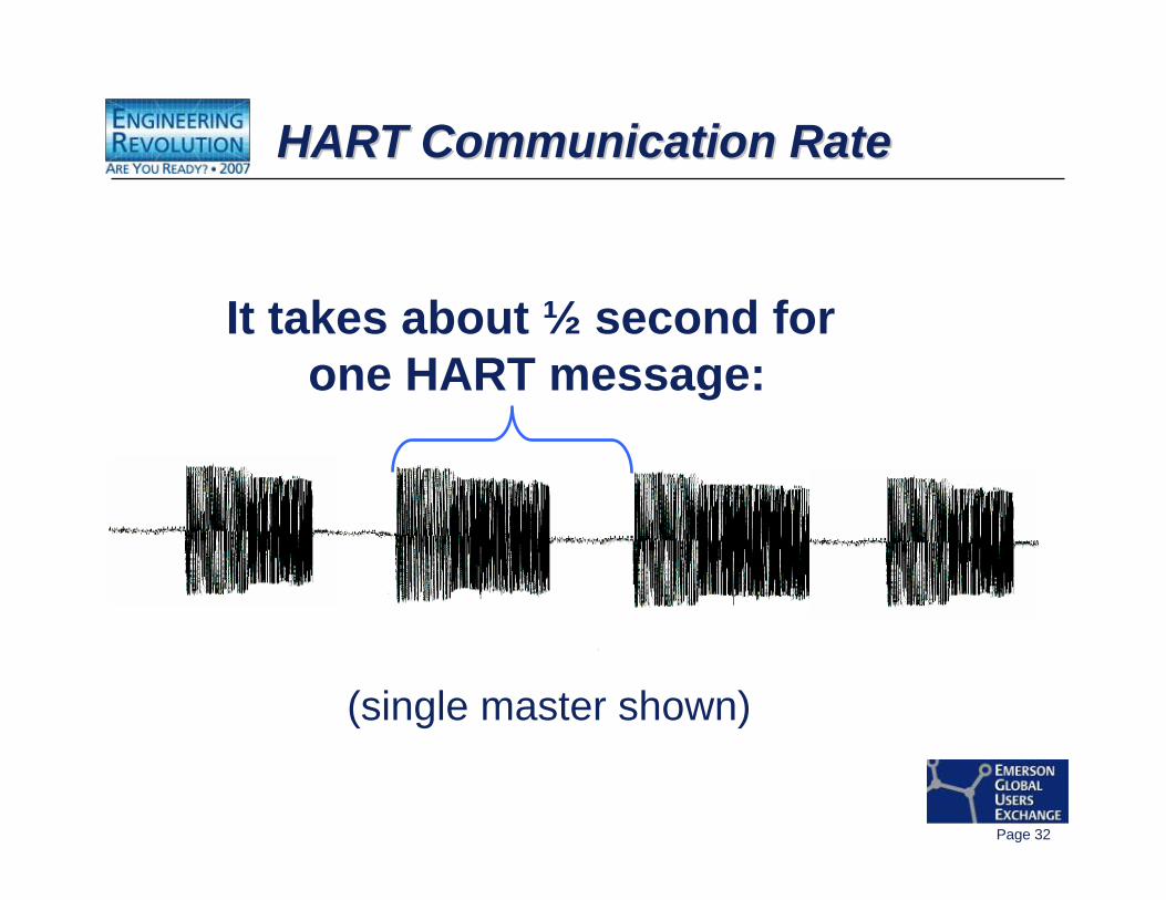
HART Communication RateHART Communication RateHART Communication Rate
It takes about ½ second for one HART message:
(single master shown)
Page 33
HART CommunicationsHART Communications
-- HART CommandsHART Commands
Page 34
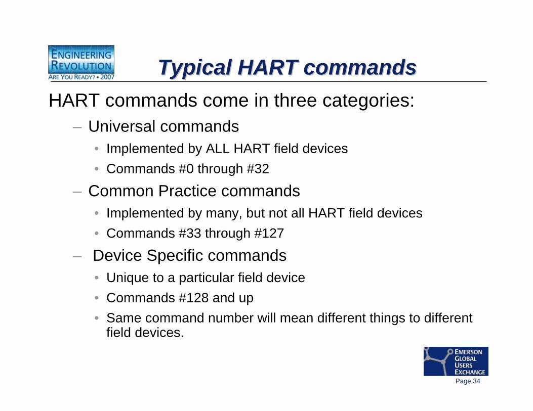
Typical HART commandsTypical HART commandsTypical HART commandsHART commands come in three categories:
– Universal commands • Implemented by ALL HART field devices• Commands #0 through #32
– Common Practice commands• Implemented by many, but not all HART field devices• Commands #33 through #127
– Device Specific commands• Unique to a particular field device• Commands #128 and up • Same command number will mean different things to different
field devices.
Page 35
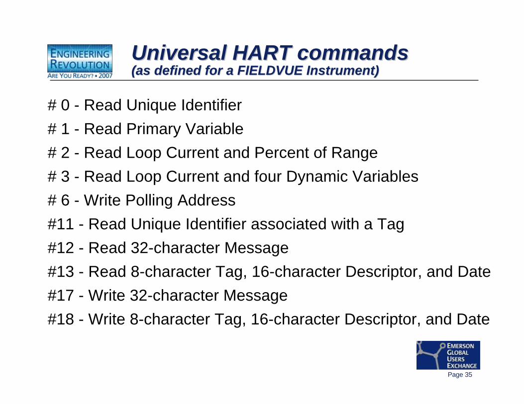
Universal HART commands(as defined for a FIELDVUE Instrument)Universal HART commandsUniversal HART commands(as defined for a FIELDVUE Instrument)(as defined for a FIELDVUE Instrument)
# 0 - Read Unique Identifier# 1 - Read Primary Variable# 2 - Read Loop Current and Percent of Range# 3 - Read Loop Current and four Dynamic Variables# 6 - Write Polling Address#11 - Read Unique Identifier associated with a Tag#12 - Read 32-character Message#13 - Read 8-character Tag, 16-character Descriptor, and Date#17 - Write 32-character Message#18 - Write 8-character Tag, 16-character Descriptor, and Date
Page 36
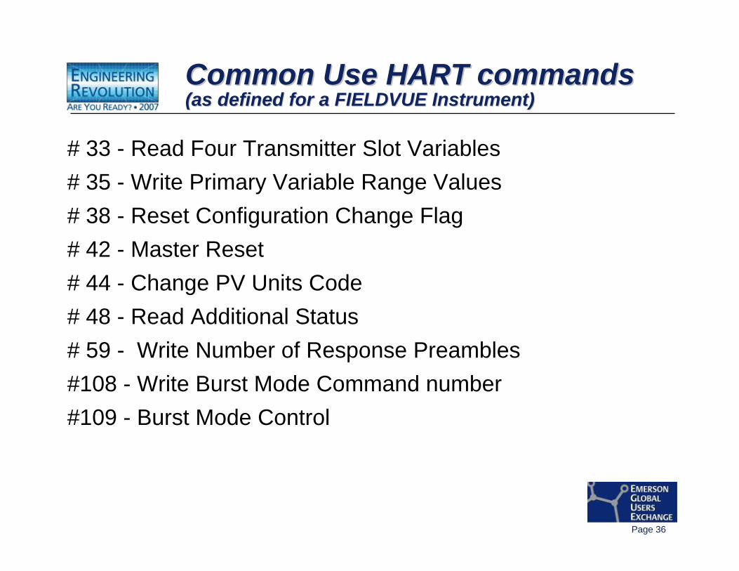
Common Use HART commands(as defined for a FIELDVUE Instrument)Common Use HART commandsCommon Use HART commands(as defined for a FIELDVUE Instrument)(as defined for a FIELDVUE Instrument)
# 33 - Read Four Transmitter Slot Variables# 35 - Write Primary Variable Range Values# 38 - Reset Configuration Change Flag# 42 - Master Reset# 44 - Change PV Units Code# 48 - Read Additional Status# 59 - Write Number of Response Preambles#108 - Write Burst Mode Command number#109 - Burst Mode Control
Page 37
Device Specific CommandsDevice Specific CommandsDevice Specific Commands
• Not listed here - they are Proprietary.• Allows for product uniqueness within an “Open”
communication protocol.• Used for special device functionality
(diagnostics, etc.).
Page 38
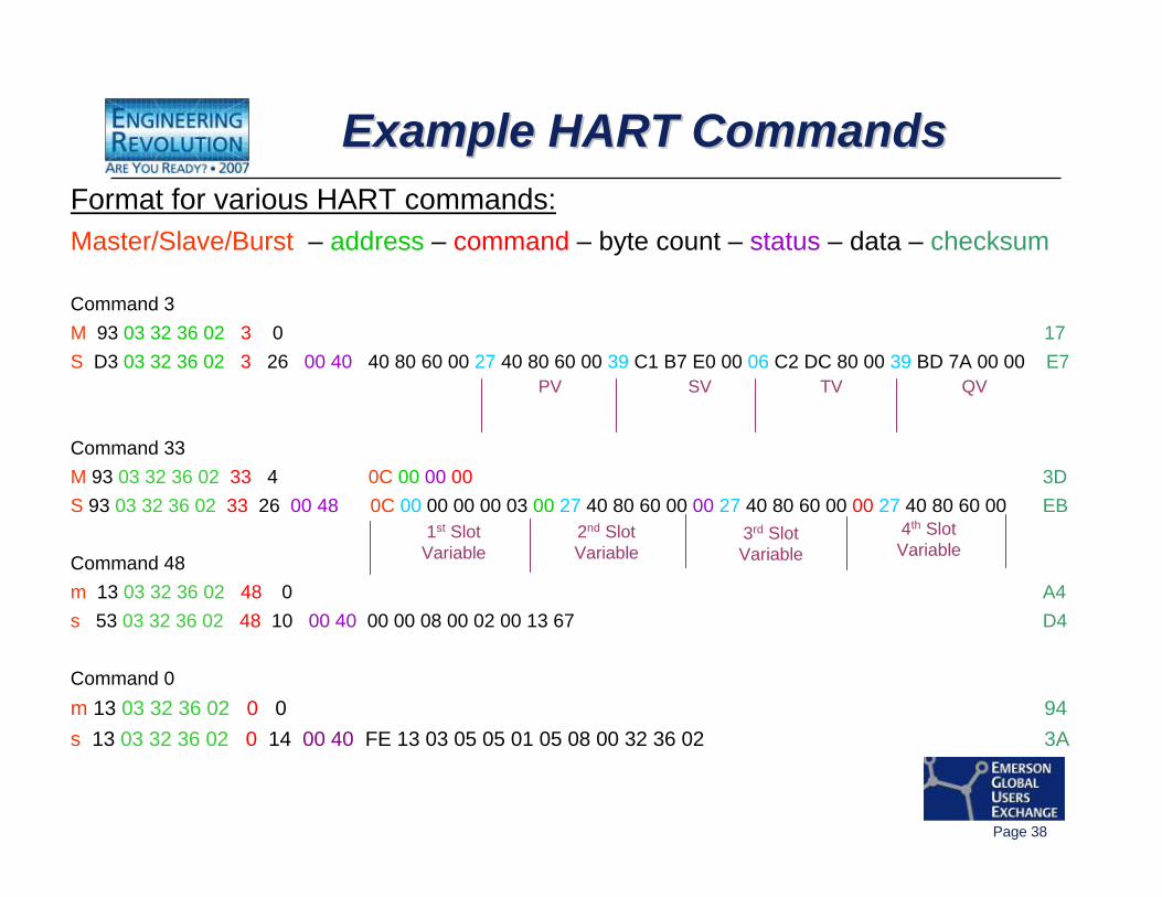
Format for various HART commands:Master/Slave/Burst – address – command – byte count – status – data – checksum
Command 3M 93 03 32 36 02 3 0 17S D3 03 32 36 02 3 26 00 40 40 80 60 00 27 40 80 60 00 39 C1 B7 E0 00 06 C2 DC 80 00 39 BD 7A 00 00 E7
Command 33M 93 03 32 36 02 33 4 0C 00 00 00 3DS 93 03 32 36 02 33 26 00 48 0C 00 00 00 00 03 00 27 40 80 60 00 00 27 40 80 60 00 00 27 40 80 60 00 EB
Command 48m 13 03 32 36 02 48 0 A4s 53 03 32 36 02 48 10 00 40 00 00 08 00 02 00 13 67 D4
Command 0m 13 03 32 36 02 0 0 94s 13 03 32 36 02 0 14 00 40 FE 13 03 05 05 01 05 08 00 32 36 02 3A
PV SV TV QV
Example HART CommandsExample HART CommandsExample HART Commands
1st SlotVariable
2nd SlotVariable
3rd SlotVariable
4th SlotVariable
Page 39
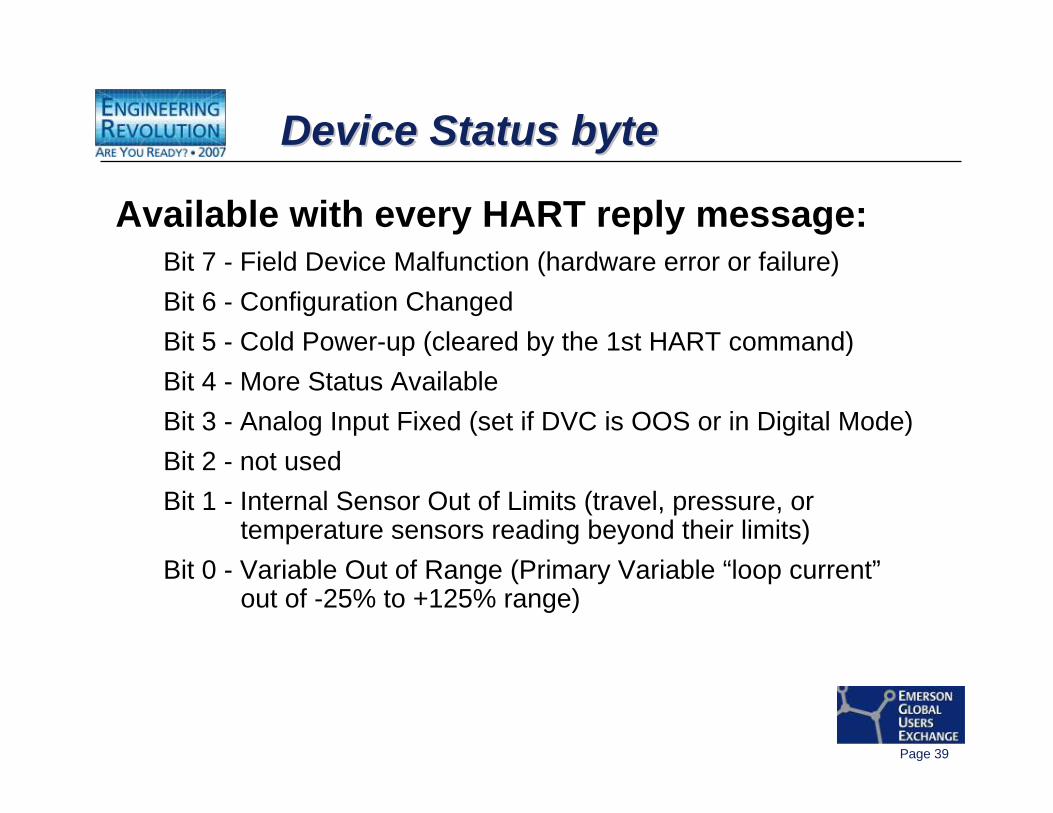
Device Status byte Device Status byte Device Status byte
Available with every HART reply message:Bit 7 - Field Device Malfunction (hardware error or failure)Bit 6 - Configuration ChangedBit 5 - Cold Power-up (cleared by the 1st HART command)Bit 4 - More Status AvailableBit 3 - Analog Input Fixed (set if DVC is OOS or in Digital Mode)Bit 2 - not usedBit 1 - Internal Sensor Out of Limits (travel, pressure, or
temperature sensors reading beyond their limits)Bit 0 - Variable Out of Range (Primary Variable “loop current”
out of -25% to +125% range)
Page 40
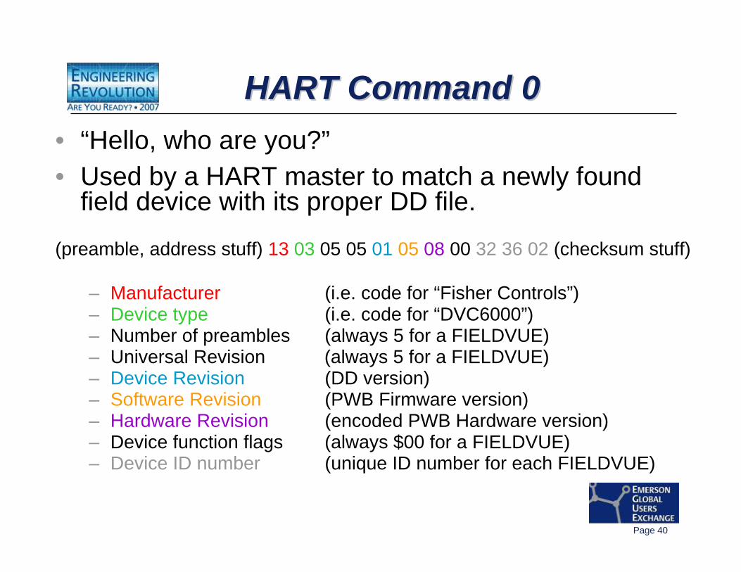
HART Command 0HART Command 0HART Command 0• “Hello, who are you?”• Used by a HART master to match a newly found
field device with its proper DD file.
(preamble, address stuff) 13 03 05 05 01 05 08 00 32 36 02 (checksum stuff)
– Manufacturer (i.e. code for “Fisher Controls”)– Device type (i.e. code for “DVC6000”)– Number of preambles (always 5 for a FIELDVUE)– Universal Revision (always 5 for a FIELDVUE)– Device Revision (DD version)– Software Revision (PWB Firmware version)– Hardware Revision (encoded PWB Hardware version)– Device function flags (always $00 for a FIELDVUE)– Device ID number (unique ID number for each FIELDVUE)
Page 41
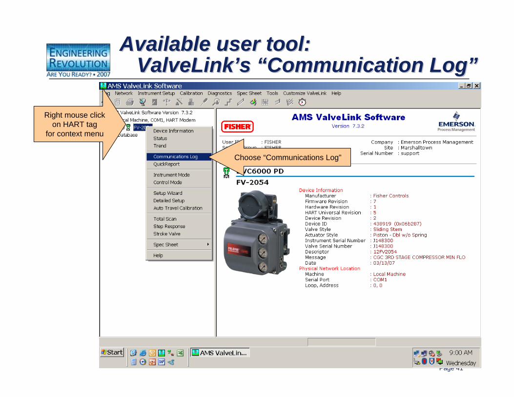
Right mouse clickon HART tag
for context menu
Choose “Communications Log”
Available user tool:ValveLink’s “Communication Log”
Available user tool:Available user tool:ValveLinkValveLink’’ss ““Communication LogCommunication Log””
Page 42
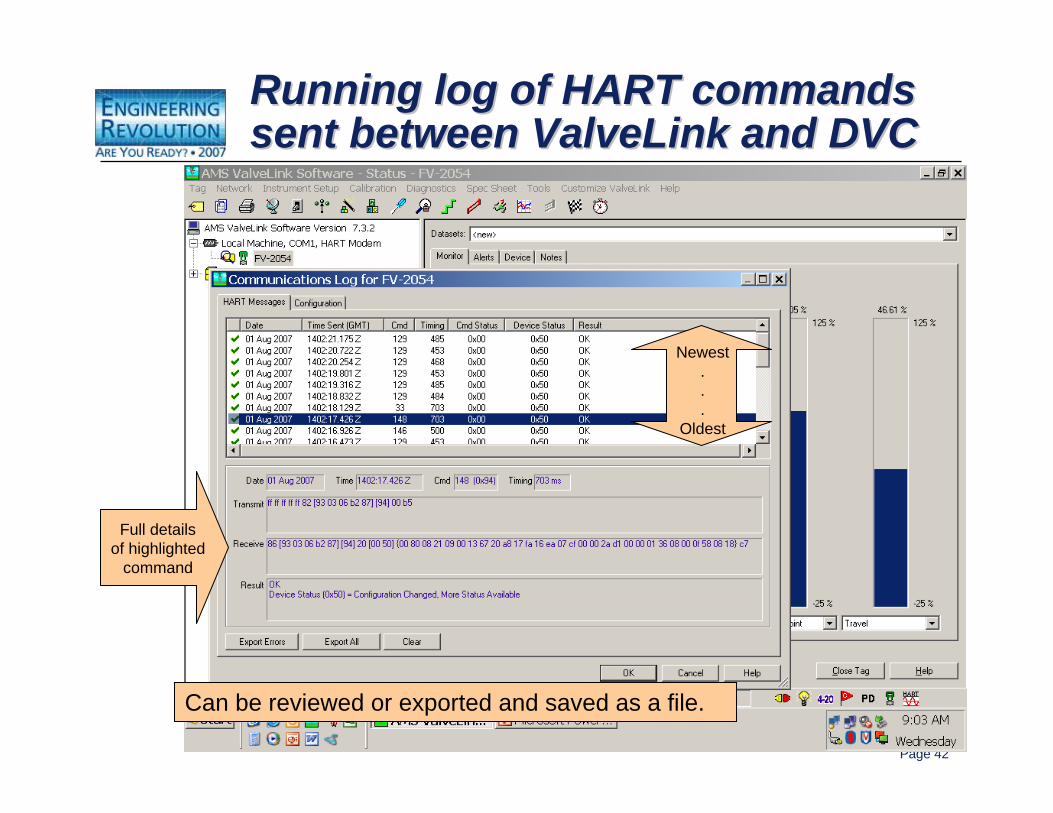
Running log of HART commands sent between ValveLink and DVCRunning log of HART commands Running log of HART commands sent between ValveLink and DVCsent between ValveLink and DVC
Newest...
Oldest
Full detailsof highlighted
command
Can be reviewed or exported and saved as a file.
Page 43
HART CommunicationsHART Communications
-- Communication ErrorsCommunication Errors
Page 44
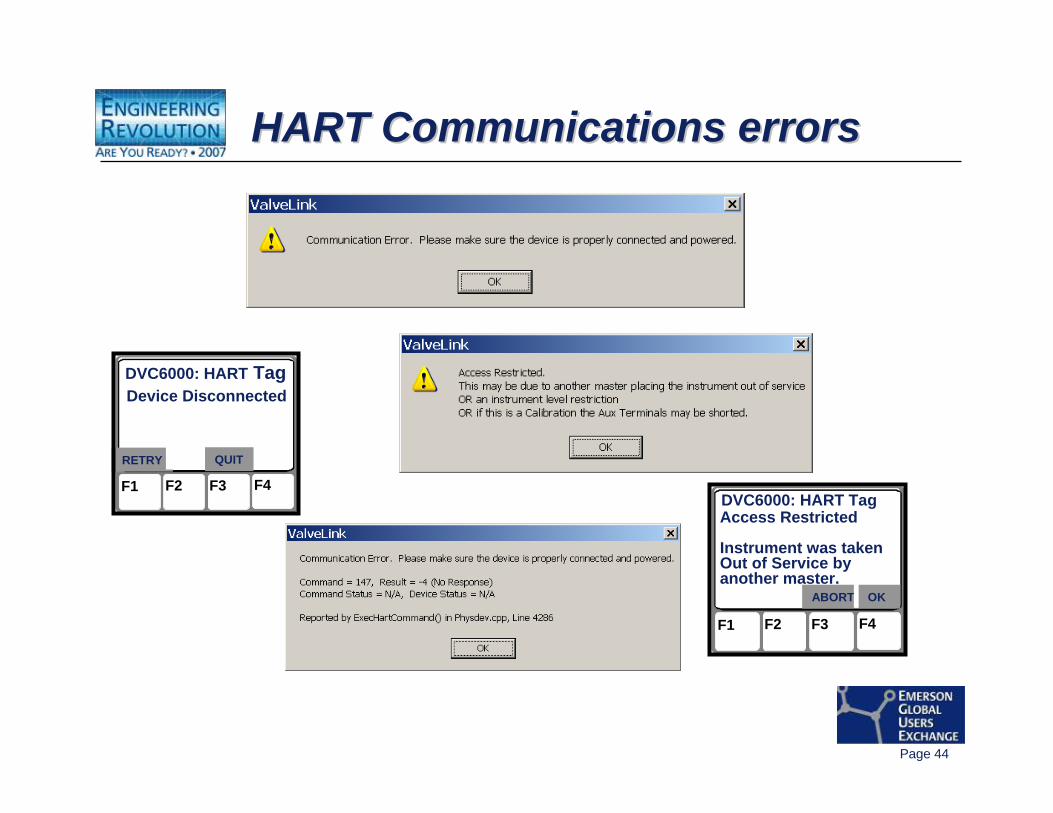
HART Communications errorsHART Communications errorsHART Communications errors
F1 F2 F3 F4
DVC6000: HART TagDevice Disconnected
RETRY QUIT
F1 F2 F3 F4
DVC6000: HART TagAccess Restricted
Instrument was takenOut of Service byanother master.
ABORT OK
Page 45
What happens when things go wrong?What happens when things go wrong?What happens when things go wrong?
You can get “HART Communication Errors” when:• Two masters of the same “gender” talk at the
same time on one loop.• A host which doesn’t arbitrate between multiple
masters very well.• Electrical noise messes up the HART signal.
Unfortunately, it’s hard to tell these apart!

Page 46
Two masters of the same “gender”talking at the same timeTwo masters of the same Two masters of the same ““gendergender””talking at the same timetalking at the same time
You manually have to separate them:• Hosts with HART AO are ALWAYS Primary master.• 275 and 375 handheld HART Communicators are
ALWAYS Secondary Master.• PC programs like AMS Device Manager® or AMS
ValveLink VL2000 Solo® or the Moore Industries’HIM® can be either master, so they are the candidates to be moved “out of the way”.
• BUT…there can only be ONE of any gender.
Page 47
A host which doesn’t arbitrate between multiple masters very wellA host which doesnA host which doesn’’t arbitrate t arbitrate between multiple masters very wellbetween multiple masters very well
• Ouch!• Most notable when things that work OK separately
do not work when connected together with a host system.
• Usually the best solution is to limit HART applications to just a single master (usually the host Primary master).
Page 48
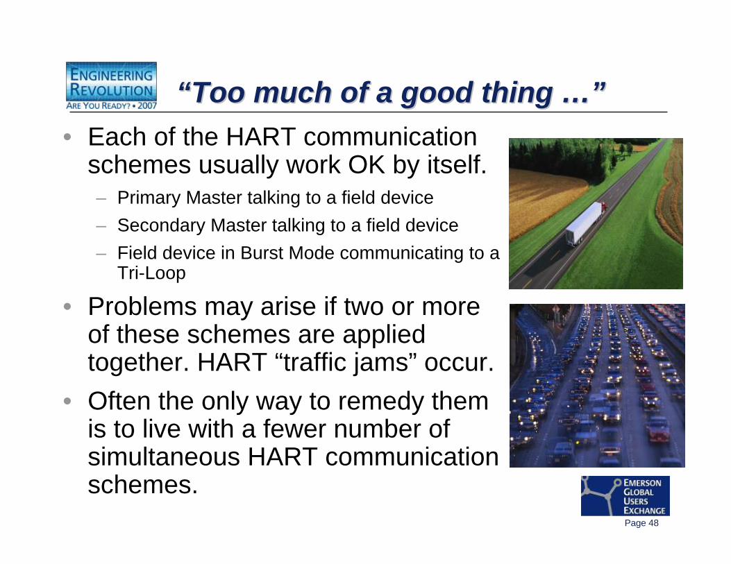
“Too much of a good thing …”““Too much of a good thing Too much of a good thing …”…”• Each of the HART communication
schemes usually work OK by itself.– Primary Master talking to a field device– Secondary Master talking to a field device– Field device in Burst Mode communicating to a
Tri-Loop
• Problems may arise if two or more of these schemes are applied together. HART “traffic jams” occur.
• Often the only way to remedy them is to live with a fewer number of simultaneous HART communication schemes.
Page 49
Demonstration
Page 50
HART CommunicationsHART Communications
-- MultiplexersMultiplexers
Page 51
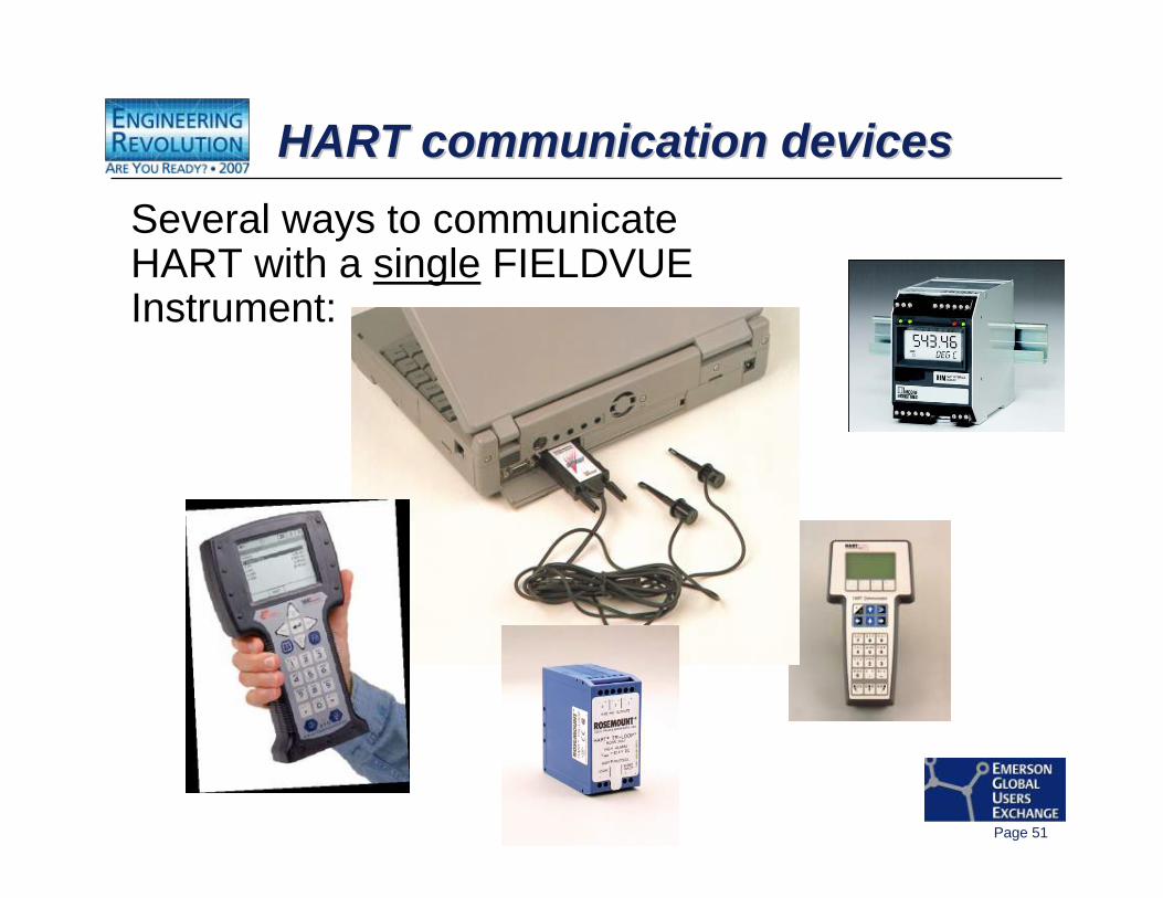
HART communication devicesHART communication devicesHART communication devicesSeveral ways to communicate HART with a single FIELDVUE Instrument:
Page 52
HART MultiplexersHART MultiplexersHART Multiplexers
What is a “Multiplexer”?• A hardware means to have physical connectivity
for HART communications to many field devices.• Contains one or more HART modems that are
shared sequentially among all connected field devices.
• Communicates with a host computer via RS485 (addressable serial data communication protocol) and communicates HART to all the connected field devices.
Page 53
What is a “multiplexer”?What is a What is a ““multiplexermultiplexer””??mul-ti-plex: being or relating to a system of transmitting several messages simultaneously on the same circuit of channel
Think of it as a HART modem in a box with lots of simultaneous electrical connections.
The four brands of HART multiplexers supported by AMS ValveLink Solo software:– ARCOM (Rosemount 2530H1 HART Interchange)– P & F KFD2-HMM-16 series– ELCON 1700 and 2700 series– MTL 4841 series
Page 54
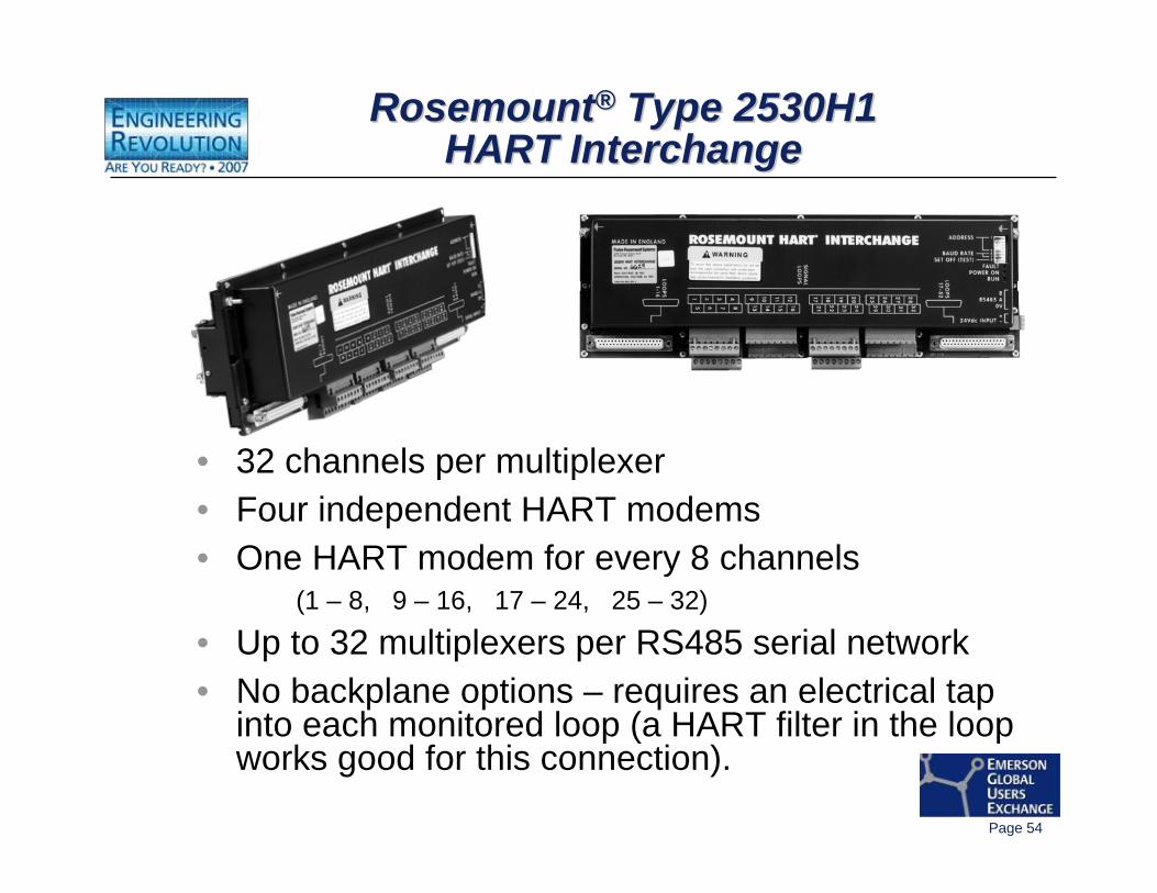
Rosemount® Type 2530H1 HART Interchange
RosemountRosemount®® Type 2530H1 Type 2530H1 HART InterchangeHART Interchange
• 32 channels per multiplexer• Four independent HART modems• One HART modem for every 8 channels
(1 – 8, 9 – 16, 17 – 24, 25 – 32)
• Up to 32 multiplexers per RS485 serial network• No backplane options – requires an electrical tap
into each monitored loop (a HART filter in the loop works good for this connection).
Page 55
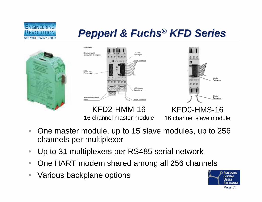
Pepperl & Fuchs® KFD SeriesPepperlPepperl & Fuchs& Fuchs®® KFD SeriesKFD Series
• One master module, up to 15 slave modules, up to 256 channels per multiplexer
• Up to 31 multiplexers per RS485 serial network• One HART modem shared among all 256 channels• Various backplane options
KFD0-HMS-1616 channel slave module
KFD2-HMM-1616 channel master module
Page 56
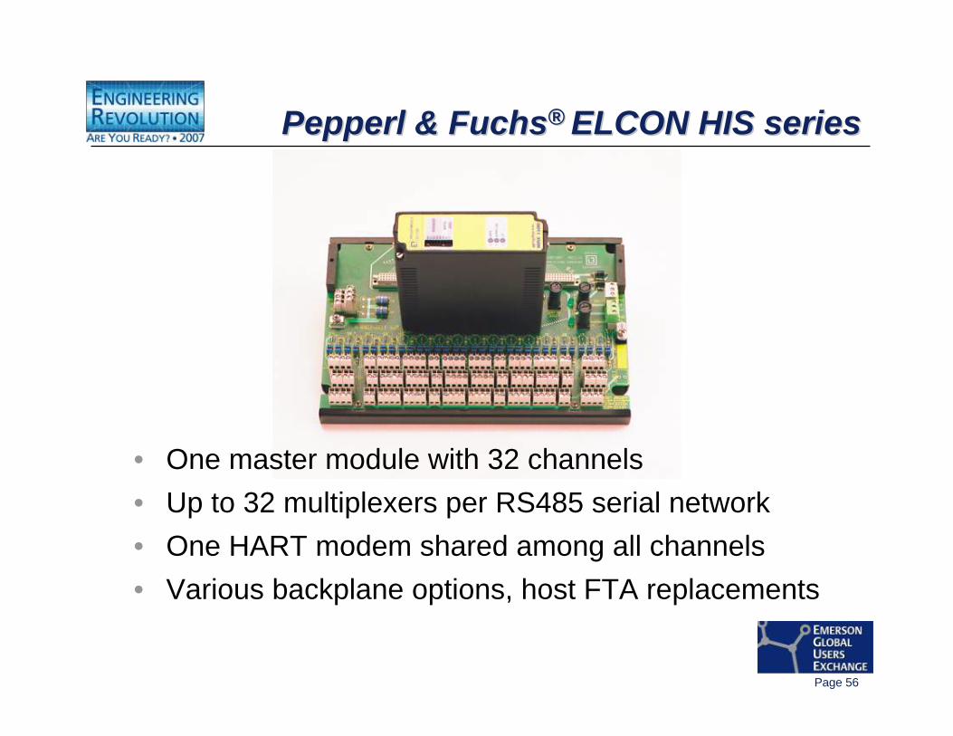
Pepperl & Fuchs® ELCON HIS seriesPepperlPepperl & Fuchs& Fuchs®® ELCON HIS seriesELCON HIS series
• One master module with 32 channels• Up to 32 multiplexers per RS485 serial network• One HART modem shared among all channels• Various backplane options, host FTA replacements
Page 57
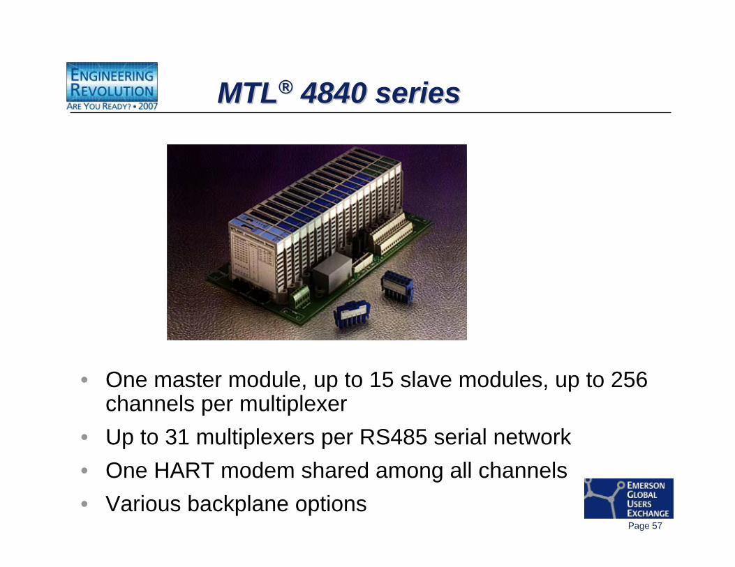
MTL® 4840 seriesMTLMTL®® 4840 series4840 series
• One master module, up to 15 slave modules, up to 256 channels per multiplexer
• Up to 31 multiplexers per RS485 serial network• One HART modem shared among all channels• Various backplane options
Page 58
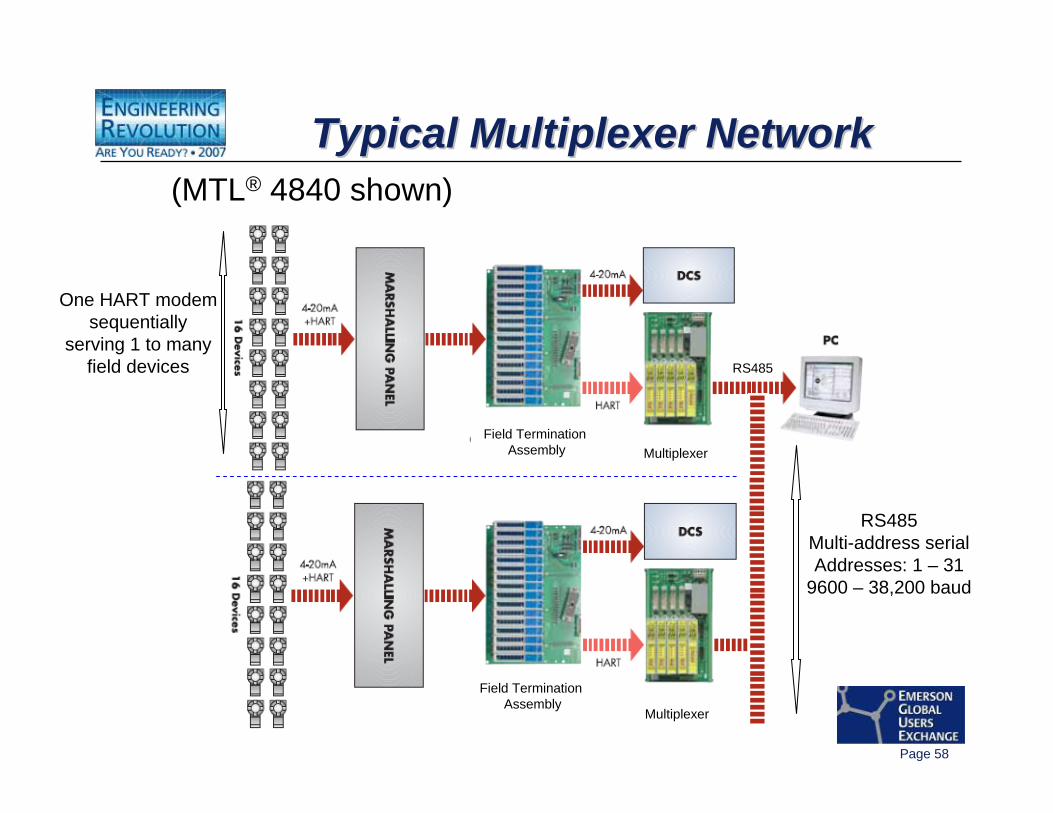
Typical Multiplexer NetworkTypical Multiplexer NetworkTypical Multiplexer Network(MTL® 4840 shown)
Multiplexer
Multiplexer
Field Termination Assembly
Field Termination Assembly
RS485
RS485Multi-address serialAddresses: 1 – 31
9600 – 38,200 baud
One HART modemsequentially
serving 1 to manyfield devices
Page 59
Network Alert ScanNetwork Alert ScanNetwork Alert Scan• An application of AMS ValveLink Solo.• Optimized to scan a defined population of
FIELDVUE instruments as quickly as possible.• It is the “engine” within AMS ValveLink Solo for
Alert Scanning, Trending, and Modbus slave functionality.
• Freshness of HART information from the scanned population of FIELDVUE instruments is important.
Page 60
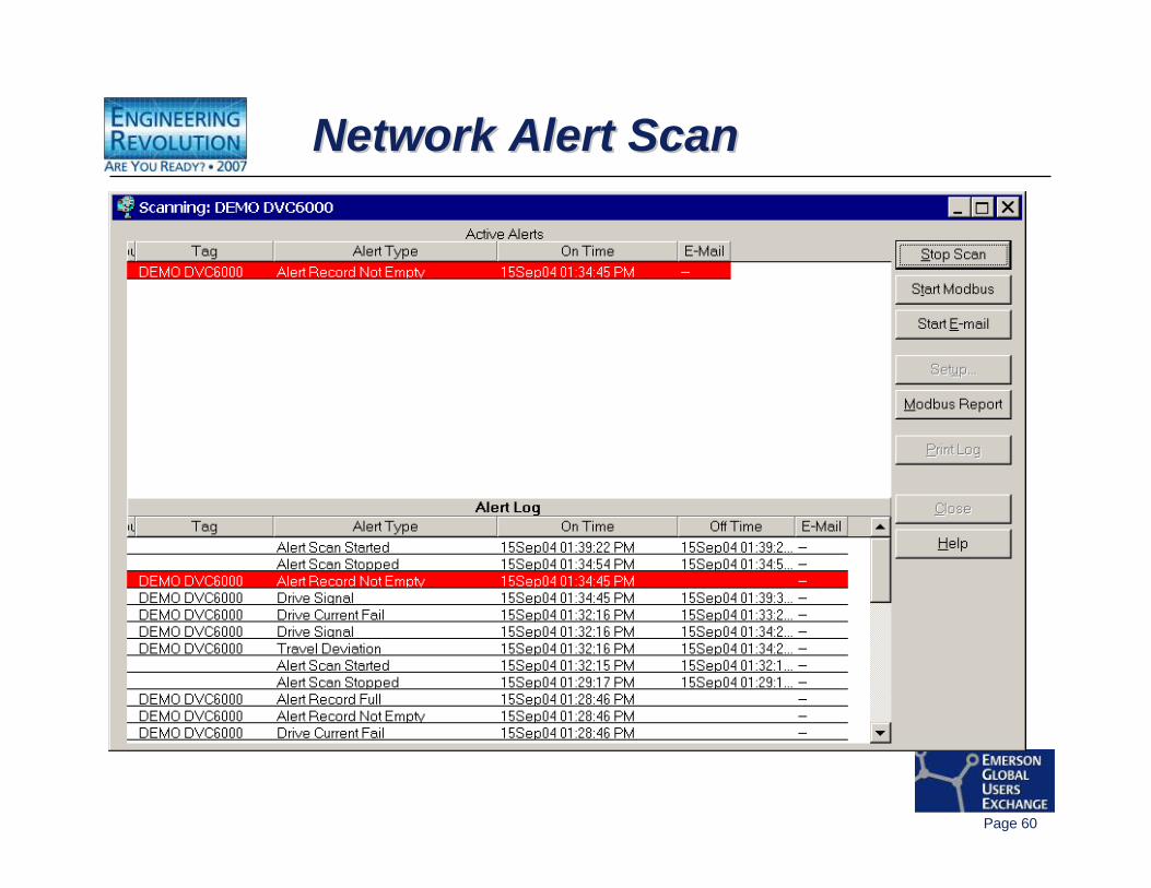
Network Alert ScanNetwork Alert ScanNetwork Alert Scan
Page 61
Mechanics of Network Alert Scan:Mechanics of Network Alert Scan:Mechanics of Network Alert Scan:
• HART Command 3 is issued to each FIELDVUE Instrument to gather its four primary variable values.
• If the “More Status Available” bit is active in the HART Command 3 reply, ValveLink issues a HART Command 48 to gather the DVC’s alert information.
Page 62
So how fast can the Network Alert Scan scan?So how fast can the Network Alert Scan So how fast can the Network Alert Scan scanscan??
Refresh Time is the time it takes AMS ValveLink Solo’s Network Alert Scan to scan its entire population of FIELDVUE devices and update its Alert Log.
Refresh Time = Multiplexer Refresh Time + Gathering Time
It is a function of:– ValveLink Network Alert Scan default settings– Number of FIELDVUE Instruments in the scan list– Number of FIELDVUE Instruments being served by one HART modem– RS485 serial communication rates between ValveLink PC’s COM port
and multiplexers– Any alert conditions existing in the FIELDVUE instruments
Page 63
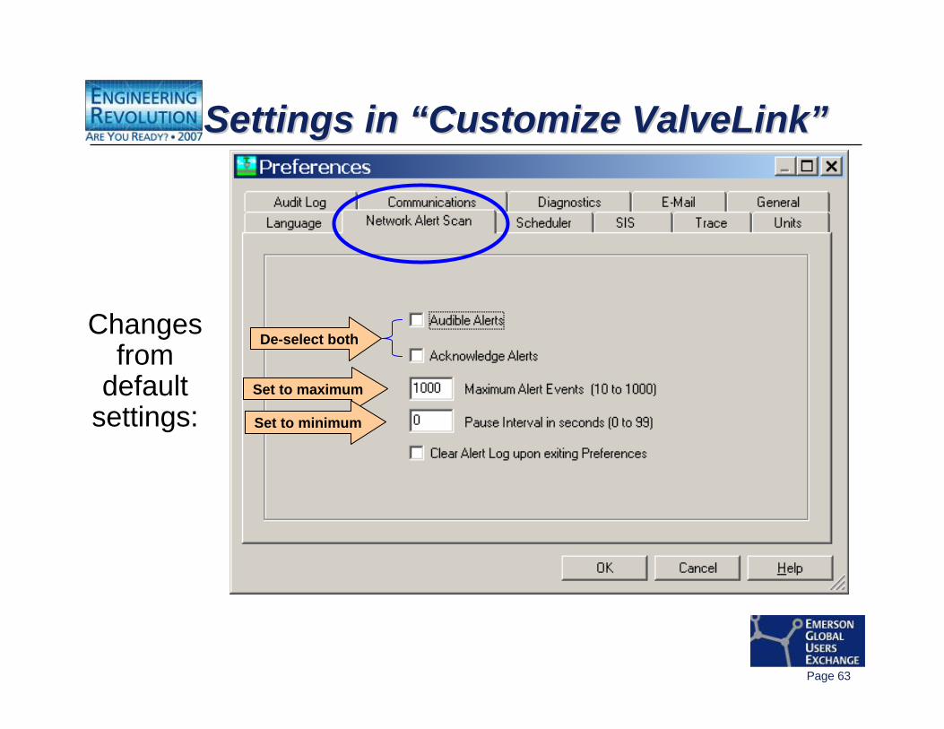
Settings in “Customize ValveLink”Settings in Settings in ““Customize ValveLinkCustomize ValveLink””
Changes from
default settings:
Set to maximum
Set to minimum
De-select both
Page 64
Multiplexer Refresh Time Multiplexer Refresh Time Multiplexer Refresh Time
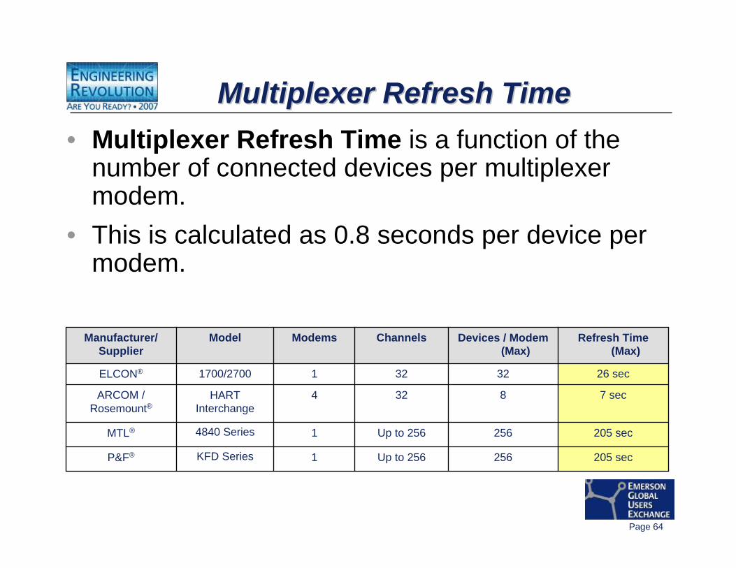
205 sec256Up to 2561KFD SeriesP&F®
205 sec256Up to 25614840 SeriesMTL®
7 sec8324HARTInterchange
ARCOM /Rosemount®
26 sec323211700/2700ELCON®
Refresh Time (Max)
Devices / Modem (Max)
ChannelsModemsModelManufacturer/Supplier
• Multiplexer Refresh Time is a function of the number of connected devices per multiplexer modem.
• This is calculated as 0.8 seconds per device per modem.
Page 65
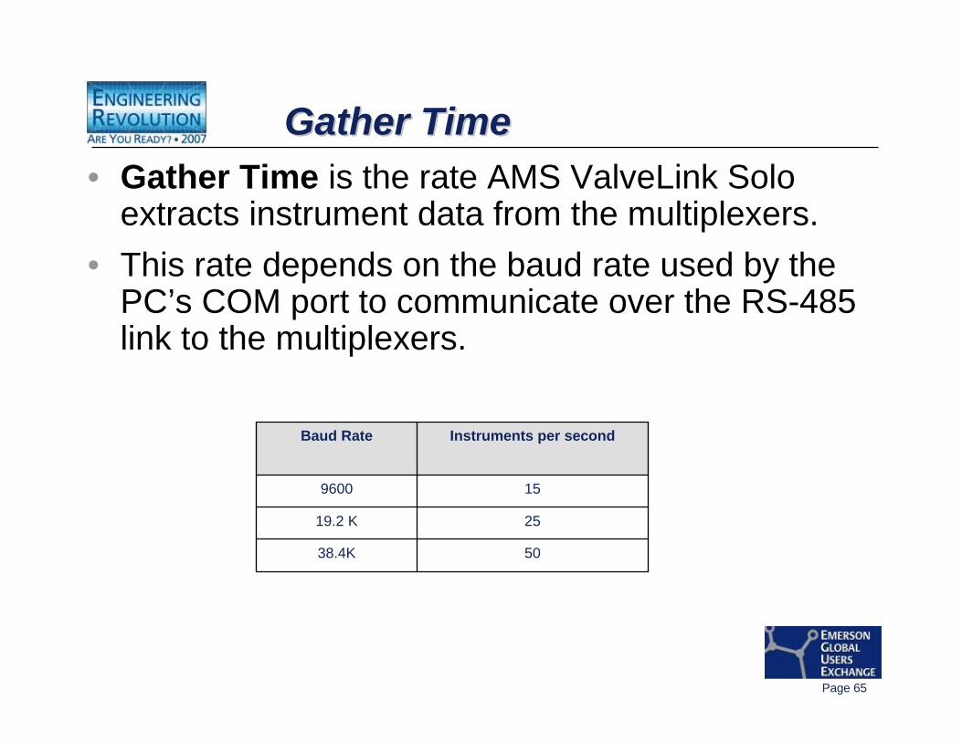
Gather TimeGather TimeGather Time• Gather Time is the rate AMS ValveLink Solo
extracts instrument data from the multiplexers. • This rate depends on the baud rate used by the
PC’s COM port to communicate over the RS-485 link to the multiplexers.
5038.4K
2519.2 K
159600
Instruments per secondBaud Rate
Page 66
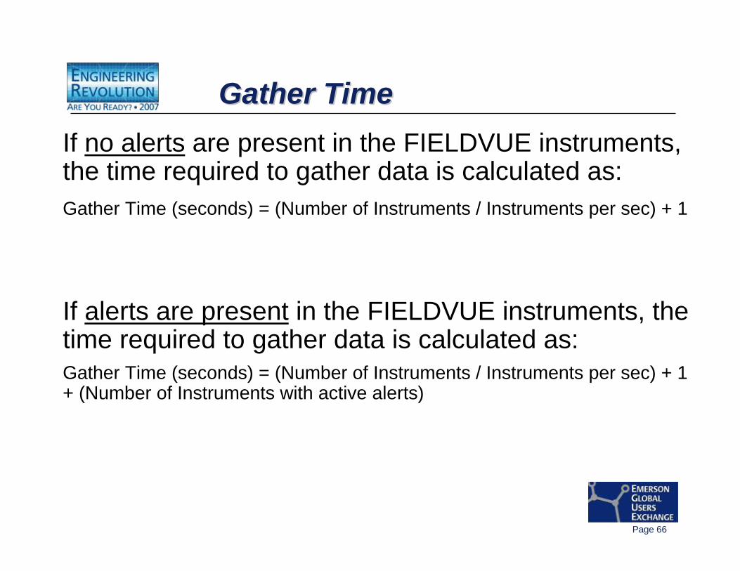
Gather TimeGather TimeGather TimeIf no alerts are present in the FIELDVUE instruments, the time required to gather data is calculated as:Gather Time (seconds) = (Number of Instruments / Instruments per sec) + 1
If alerts are present in the FIELDVUE instruments, the time required to gather data is calculated as:Gather Time (seconds) = (Number of Instruments / Instruments per sec) + 1 + (Number of Instruments with active alerts)
Page 67
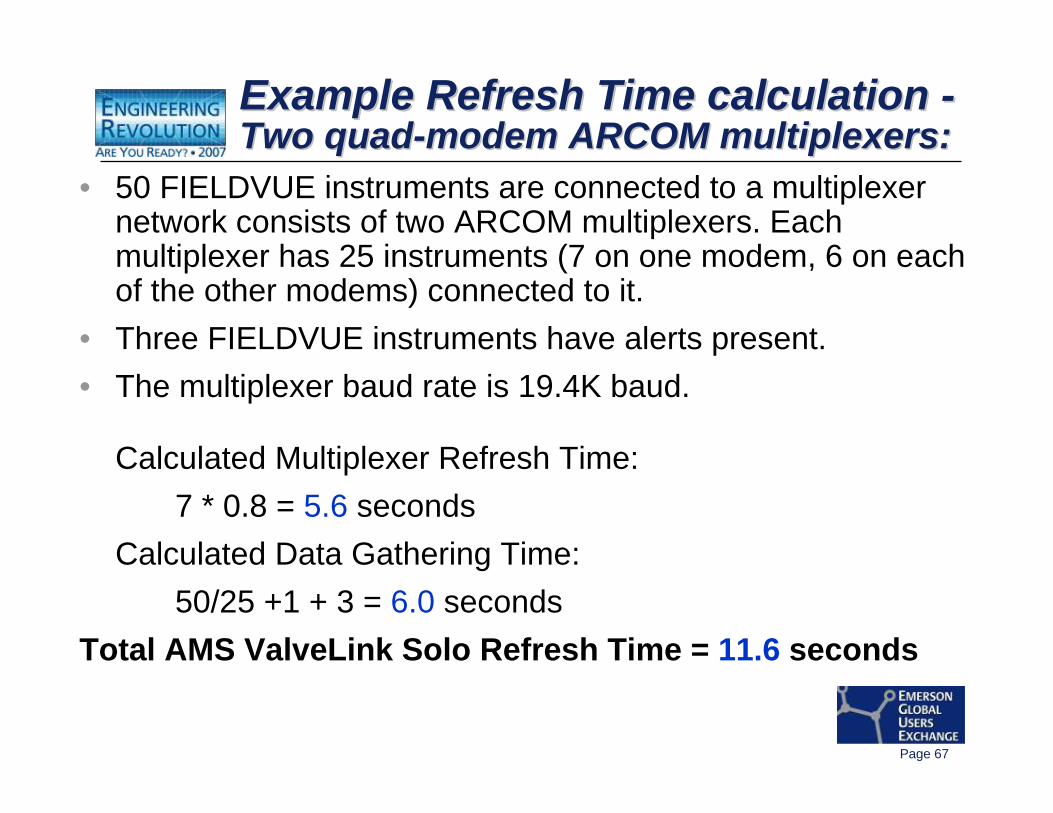
Example Refresh Time calculation -Two quad-modem ARCOM multiplexers:Example Refresh Time calculation Example Refresh Time calculation --Two quadTwo quad--modem ARCOM multiplexers:modem ARCOM multiplexers:
• 50 FIELDVUE instruments are connected to a multiplexer network consists of two ARCOM multiplexers. Each multiplexer has 25 instruments (7 on one modem, 6 on each of the other modems) connected to it.
• Three FIELDVUE instruments have alerts present. • The multiplexer baud rate is 19.4K baud.
Calculated Multiplexer Refresh Time:7 * 0.8 = 5.6 seconds
Calculated Data Gathering Time:50/25 +1 + 3 = 6.0 seconds
Total AMS ValveLink Solo Refresh Time = 11.6 seconds
Page 68
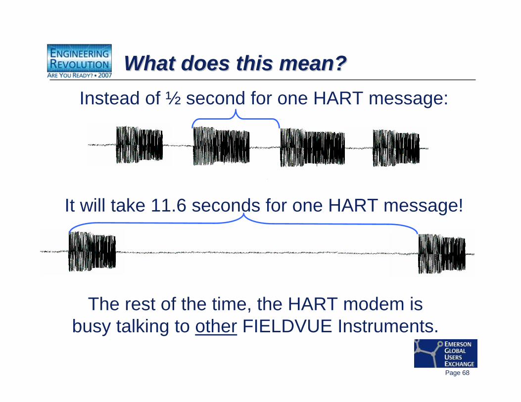
What does this mean?What does this mean?What does this mean?Instead of ½ second for one HART message:
It will take 11.6 seconds for one HART message!
The rest of the time, the HART modem isbusy talking to other FIELDVUE Instruments.
Page 69
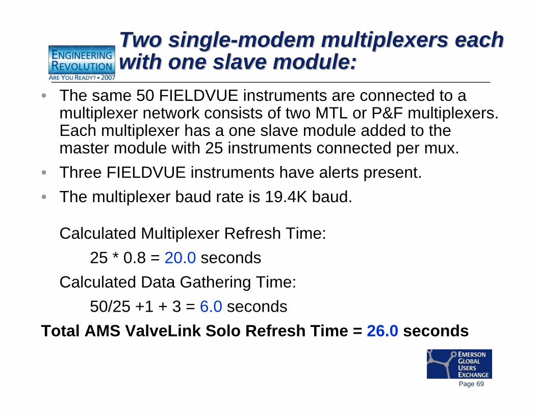
Two single-modem multiplexers each with one slave module:Two singleTwo single--modem multiplexers each modem multiplexers each with one slave module:with one slave module:
• The same 50 FIELDVUE instruments are connected to a multiplexer network consists of two MTL or P&F multiplexers. Each multiplexer has a one slave module added to the master module with 25 instruments connected per mux.
• Three FIELDVUE instruments have alerts present. • The multiplexer baud rate is 19.4K baud.
Calculated Multiplexer Refresh Time:25 * 0.8 = 20.0 seconds
Calculated Data Gathering Time:50/25 +1 + 3 = 6.0 seconds
Total AMS ValveLink Solo Refresh Time = 26.0 seconds
Page 70
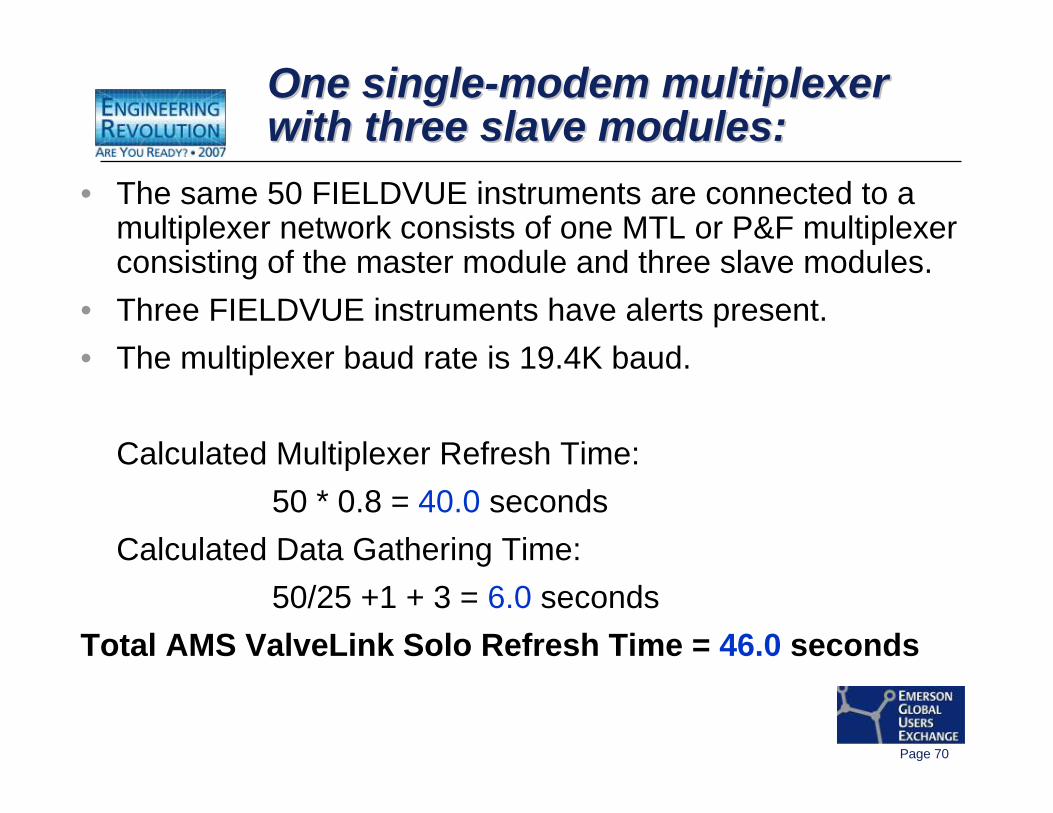
• The same 50 FIELDVUE instruments are connected to a multiplexer network consists of one MTL or P&F multiplexer consisting of the master module and three slave modules.
• Three FIELDVUE instruments have alerts present. • The multiplexer baud rate is 19.4K baud.
Calculated Multiplexer Refresh Time:50 * 0.8 = 40.0 seconds
Calculated Data Gathering Time:50/25 +1 + 3 = 6.0 seconds
Total AMS ValveLink Solo Refresh Time = 46.0 seconds
One single-modem multiplexer with three slave modules:One singleOne single--modem multiplexer modem multiplexer with three slave modules:with three slave modules:
Page 71
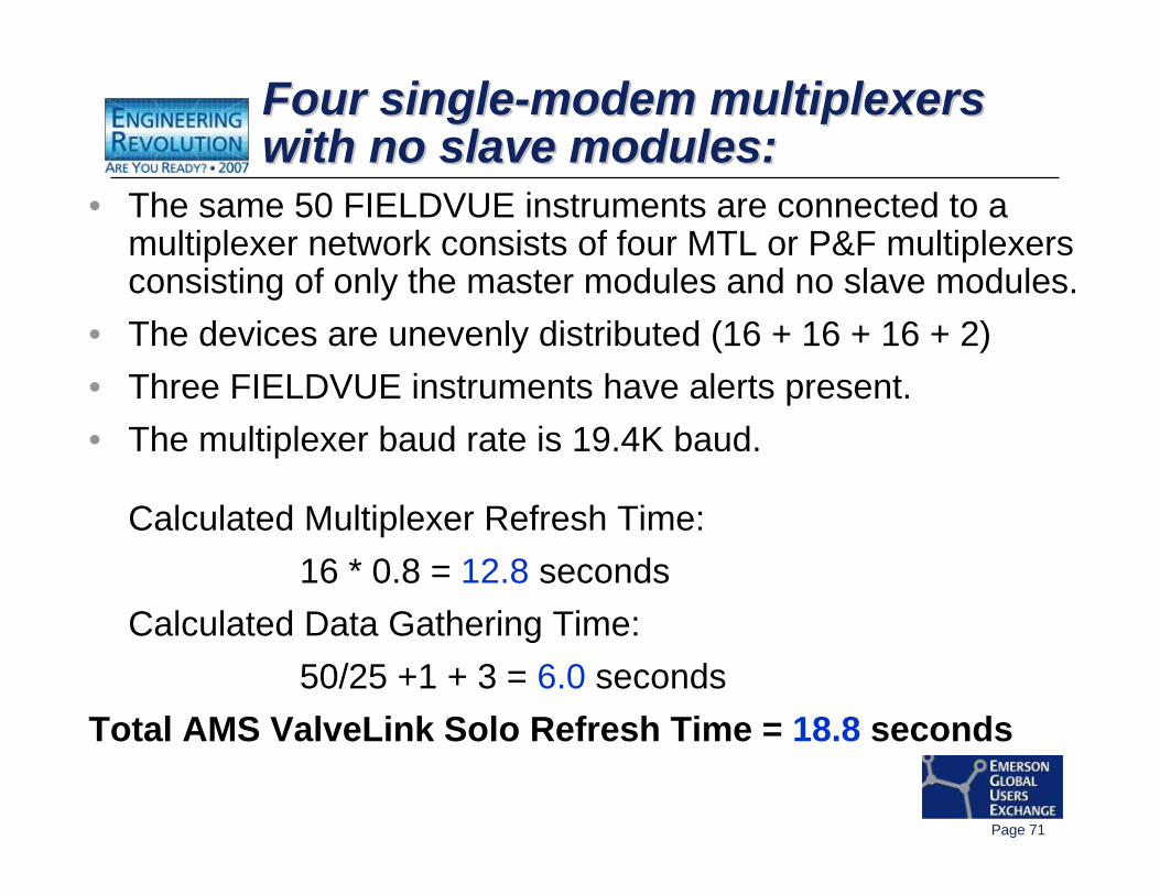
• The same 50 FIELDVUE instruments are connected to a multiplexer network consists of four MTL or P&F multiplexers consisting of only the master modules and no slave modules.
• The devices are unevenly distributed (16 + 16 + 16 + 2)• Three FIELDVUE instruments have alerts present. • The multiplexer baud rate is 19.4K baud.
Calculated Multiplexer Refresh Time:16 * 0.8 = 12.8 seconds
Calculated Data Gathering Time:50/25 +1 + 3 = 6.0 seconds
Total AMS ValveLink Solo Refresh Time = 18.8 seconds
Four single-modem multiplexers with no slave modules:Four singleFour single--modem multiplexers modem multiplexers with no slave modules:with no slave modules:
Page 72
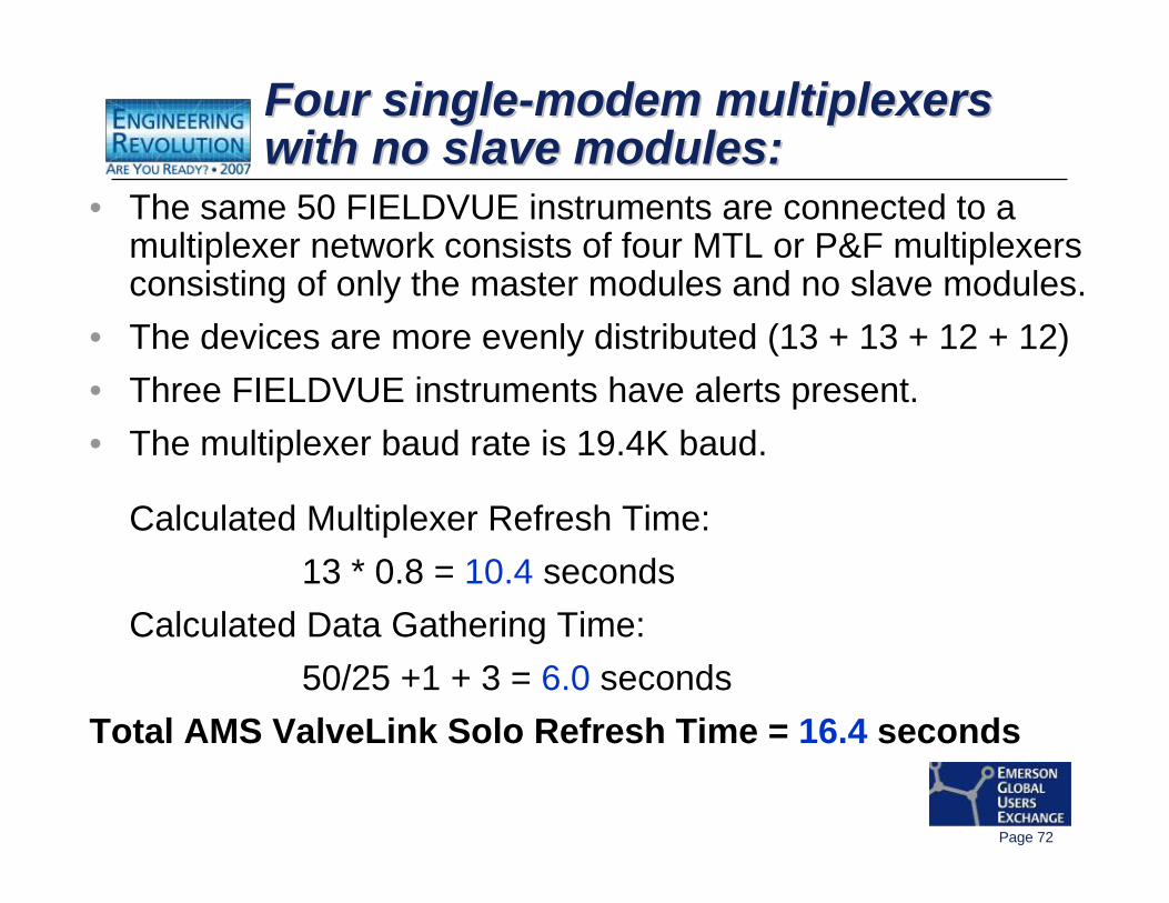
• The same 50 FIELDVUE instruments are connected to a multiplexer network consists of four MTL or P&F multiplexers consisting of only the master modules and no slave modules.
• The devices are more evenly distributed (13 + 13 + 12 + 12) • Three FIELDVUE instruments have alerts present. • The multiplexer baud rate is 19.4K baud.
Calculated Multiplexer Refresh Time: 13 * 0.8 = 10.4 seconds
Calculated Data Gathering Time:50/25 +1 + 3 = 6.0 seconds
Total AMS ValveLink Solo Refresh Time = 16.4 seconds
Four single-modem multiplexers with no slave modules:Four singleFour single--modem multiplexers modem multiplexers with no slave modules:with no slave modules:
Page 73
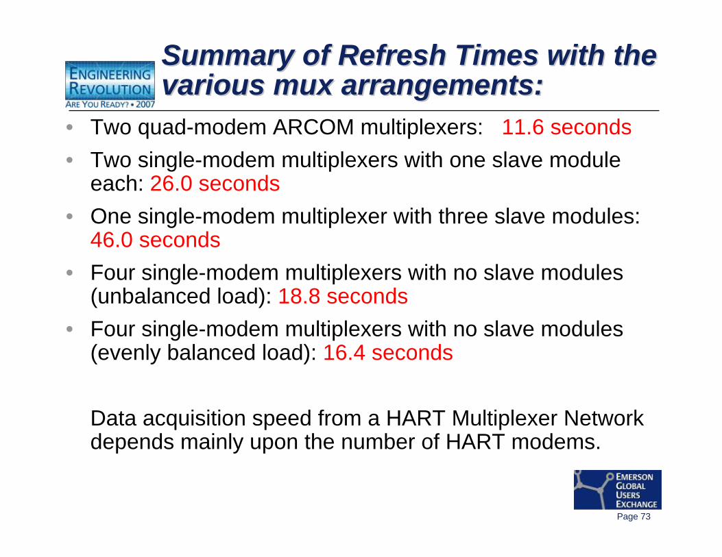
Summary of Refresh Times with the various mux arrangements:Summary of Refresh Times with the Summary of Refresh Times with the various mux arrangements:various mux arrangements:
• Two quad-modem ARCOM multiplexers: 11.6 seconds• Two single-modem multiplexers with one slave module
each: 26.0 seconds• One single-modem multiplexer with three slave modules:
46.0 seconds• Four single-modem multiplexers with no slave modules
(unbalanced load): 18.8 seconds• Four single-modem multiplexers with no slave modules
(evenly balanced load): 16.4 seconds
Data acquisition speed from a HART Multiplexer Network depends mainly upon the number of HART modems.
Page 74
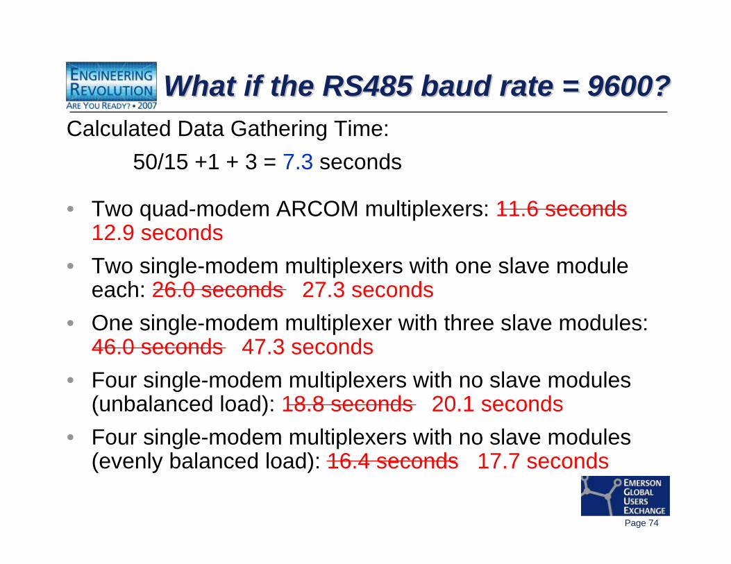
What if the RS485 baud rate = 9600?What if the RS485 baud rate = 9600?What if the RS485 baud rate = 9600?Calculated Data Gathering Time:
50/15 +1 + 3 = 7.3 seconds
• Two quad-modem ARCOM multiplexers: 11.6 seconds 12.9 seconds
• Two single-modem multiplexers with one slave module each: 26.0 seconds 27.3 seconds
• One single-modem multiplexer with three slave modules: 46.0 seconds 47.3 seconds
• Four single-modem multiplexers with no slave modules (unbalanced load): 18.8 seconds 20.1 seconds
• Four single-modem multiplexers with no slave modules (evenly balanced load): 16.4 seconds 17.7 seconds
Page 75
Multiplexer summary:Multiplexer summary:Multiplexer summary:• Handy way to electrically connect numerous
FIELDVUE Instruments to the PC software.• Pay the price with HART scanning speed.• The fastest scanning will be with the least number
of devices per HART modem.• Increasing RS485 baud rate helps, but not by
much compared to HART modems.• Load Balancing so that similar number of devices
are on each modem optimizes the scanning speed.
Page 76
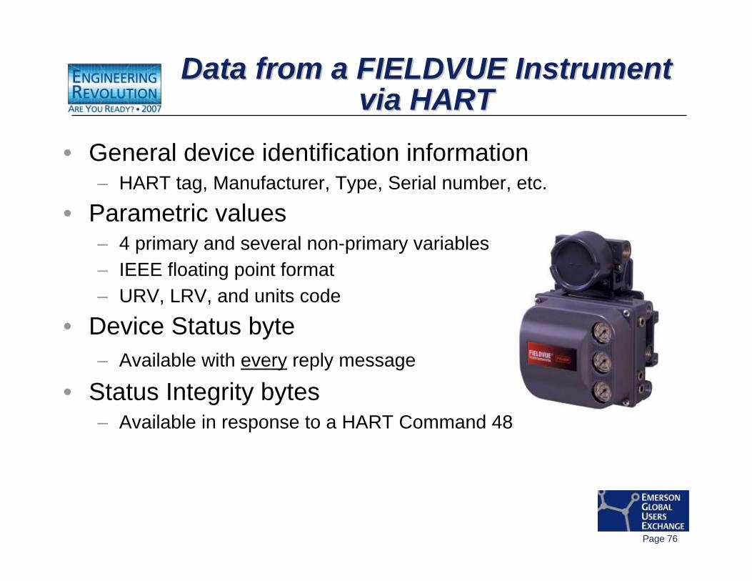
Data from a FIELDVUE Instrument via HART
Data from a FIELDVUE Instrument Data from a FIELDVUE Instrument via HARTvia HART
• General device identification information– HART tag, Manufacturer, Type, Serial number, etc.
• Parametric values– 4 primary and several non-primary variables– IEEE floating point format– URV, LRV, and units code
• Device Status byte– Available with every reply message
• Status Integrity bytes– Available in response to a HART Command 48
Page 77
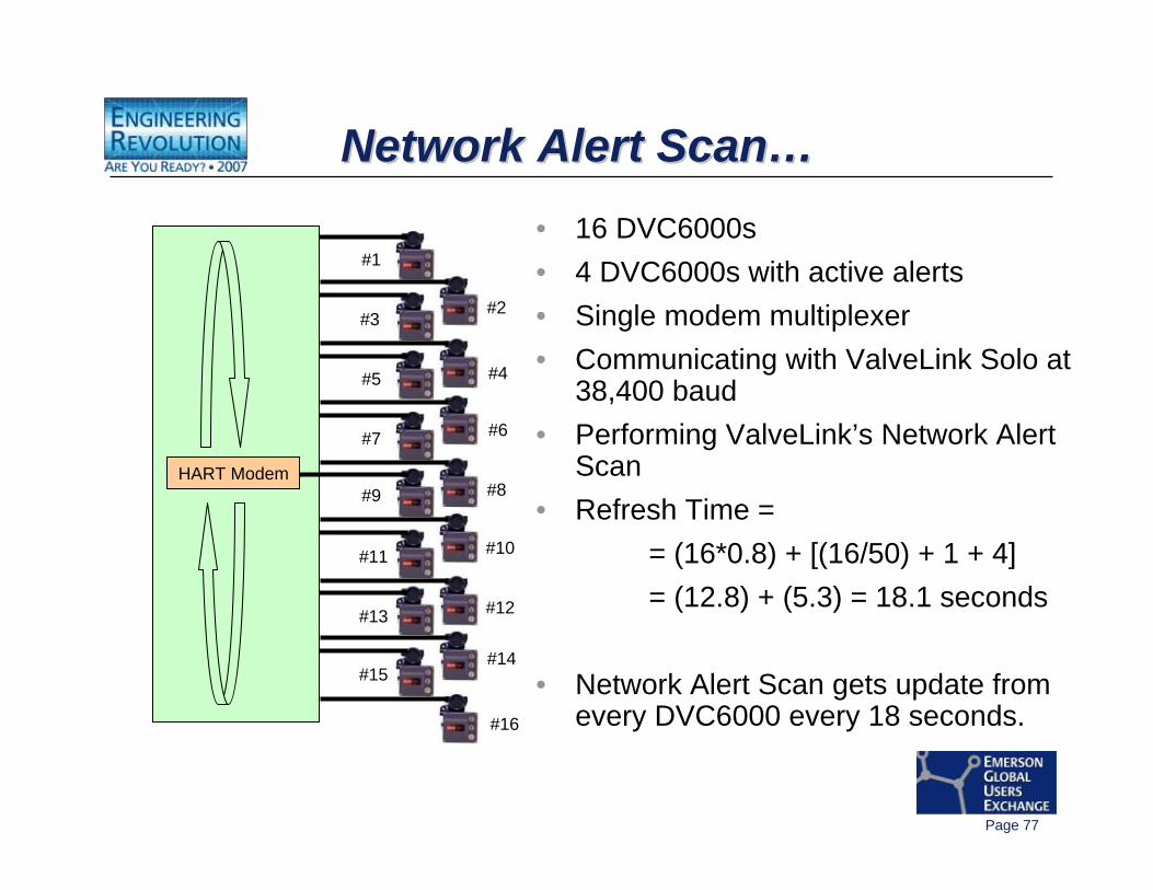
Network Alert Scan…Network Alert ScanNetwork Alert Scan……• 16 DVC6000s• 4 DVC6000s with active alerts• Single modem multiplexer• Communicating with ValveLink Solo at
38,400 baud• Performing ValveLink’s Network Alert
Scan• Refresh Time =
= (16*0.8) + [(16/50) + 1 + 4]= (12.8) + (5.3) = 18.1 seconds
• Network Alert Scan gets update from every DVC6000 every 18 seconds.
HART Modem
#1
#3
#5
#7
#9
#11
#13
#15
#12
#10
#14
#16
#2
#4
#6
#8
Page 78
What happens when a FIELDVUE Instrument
experiences an intermittent fault?
Is it detected by the Network Alert Scan?
Page 79
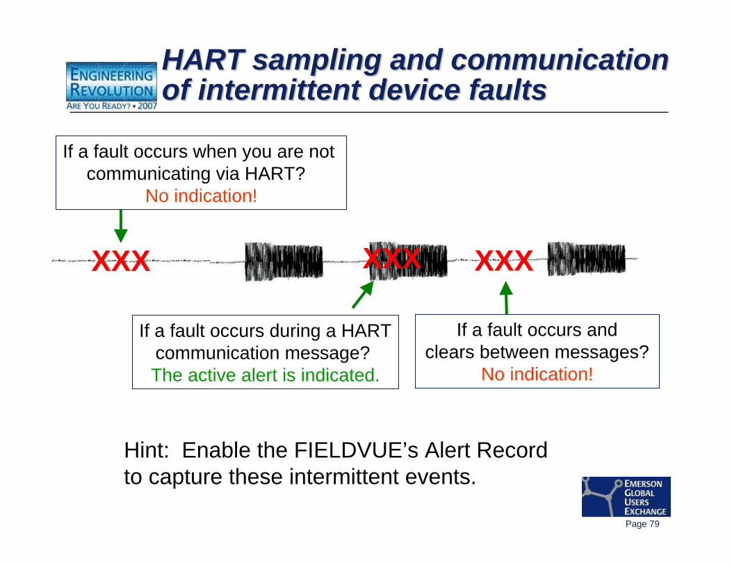
If a fault occurs and clears between messages?
No indication!
If a fault occurs during a HARTcommunication message? The active alert is indicated.
HART sampling and communication of intermittent device faultsHART sampling and communication HART sampling and communication of intermittent device faultsof intermittent device faults
XXX XXXXXX
If a fault occurs when you are not communicating via HART?
No indication!
Hint: Enable the FIELDVUE’s Alert Recordto capture these intermittent events.
Page 80
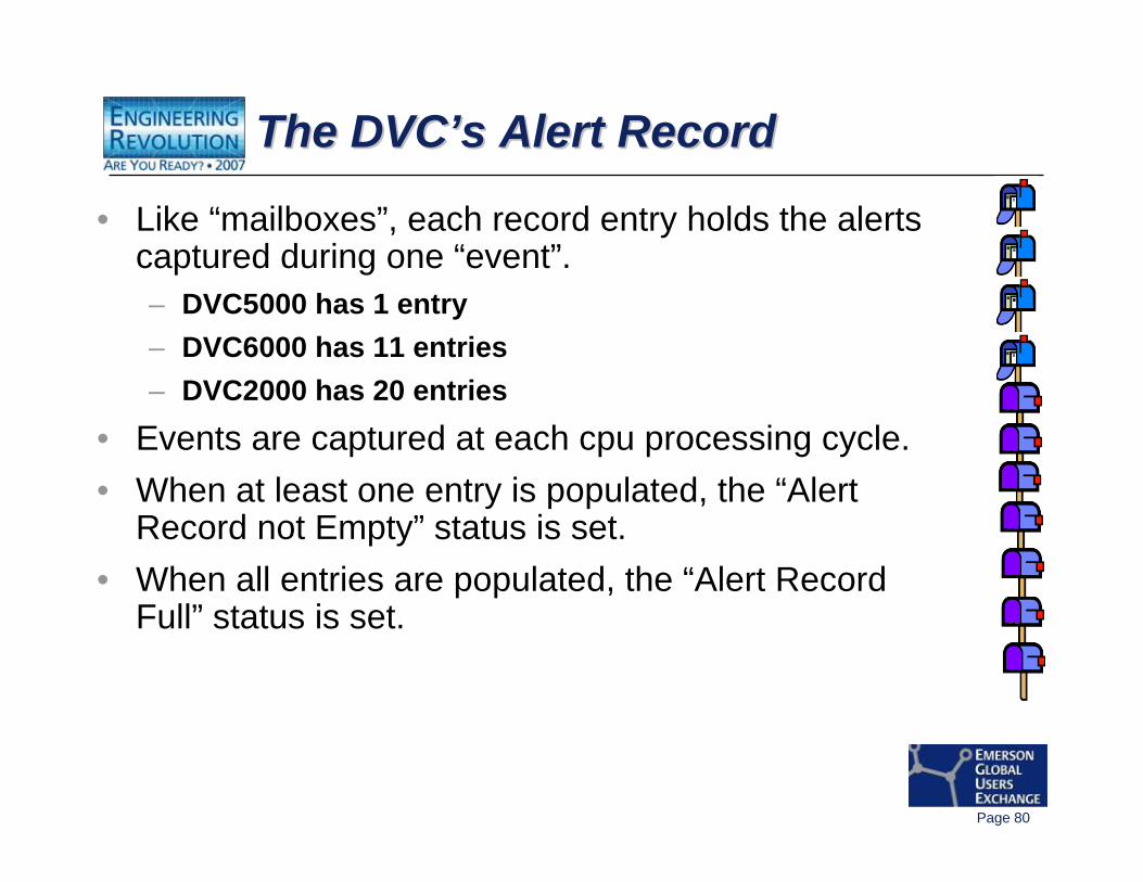
The DVC’s Alert RecordThe DVCThe DVC’’s Alert Records Alert Record
• Like “mailboxes”, each record entry holds the alerts captured during one “event”.– DVC5000 has 1 entry – DVC6000 has 11 entries – DVC2000 has 20 entries
• Events are captured at each cpu processing cycle.• When at least one entry is populated, the “Alert
Record not Empty” status is set.• When all entries are populated, the “Alert Record
Full” status is set.
Page 81
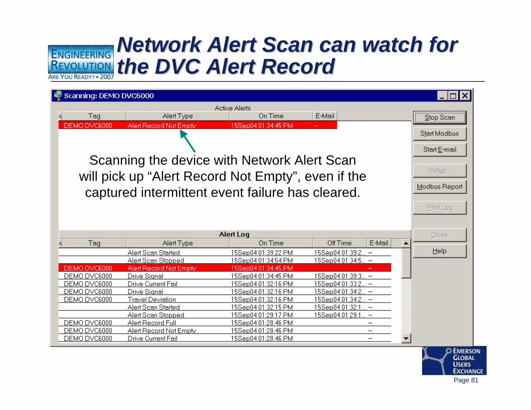
Network Alert Scan can watch for the DVC Alert Record Network Alert Scan can watch for Network Alert Scan can watch for the DVC Alert Record the DVC Alert Record
Scanning the device with Network Alert Scanwill pick up “Alert Record Not Empty”, even if thecaptured intermittent event failure has cleared.
Page 82
HART CommunicationsHART Communications
-- SummarySummary
Page 83
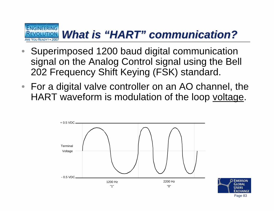
What is “HART” communication?What is What is ““HARTHART”” communication?communication?• Superimposed 1200 baud digital communication
signal on the Analog Control signal using the Bell 202 Frequency Shift Keying (FSK) standard.
• For a digital valve controller on an AO channel, the HART waveform is modulation of the loop voltage.
TerminalVoltage
2200 Hz1200 Hz"1" "0"
+ 0.5 VDC
- 0.5 VDC
Page 84
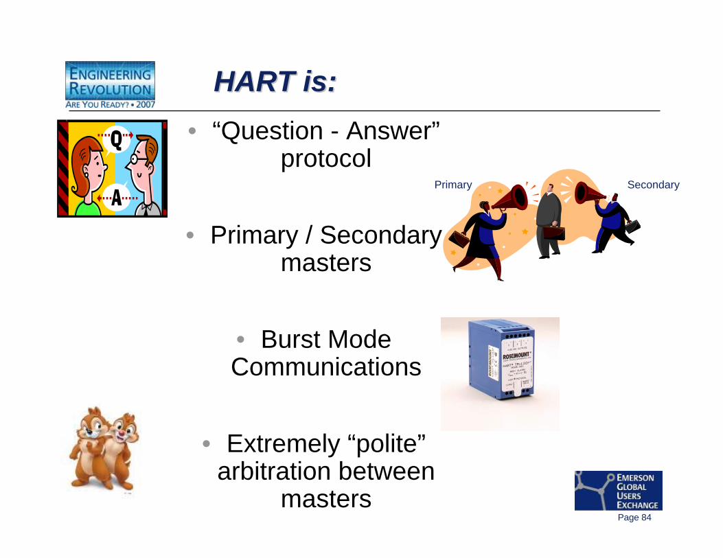
HART is:HART is:HART is:• “Question - Answer”
protocol
• Primary / Secondary masters
• Burst Mode Communications
• Extremely “polite”arbitration between
masters
Primary Secondary
Page 85
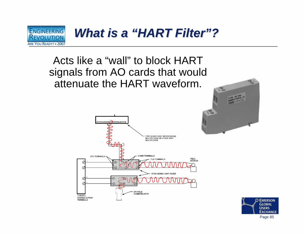
What is a “HART Filter”?What is a What is a ““HART FilterHART Filter””??
Acts like a “wall” to block HART signals from AO cards that would attenuate the HART waveform.
Page 86
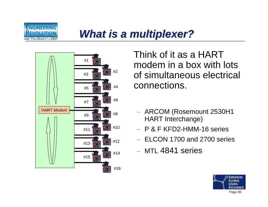
What is a multiplexer?What is a multiplexer?What is a multiplexer?
Think of it as a HART modem in a box with lots of simultaneous electrical connections.
– ARCOM (Rosemount 2530H1 HART Interchange)
– P & F KFD2-HMM-16 series– ELCON 1700 and 2700 series
– MTL 4841 series
HART Modem
#1
#3
#5
#7
#9
#11
#13
#15
#12
#10
#14
#16
#2
#4
#6
#8
Page 87
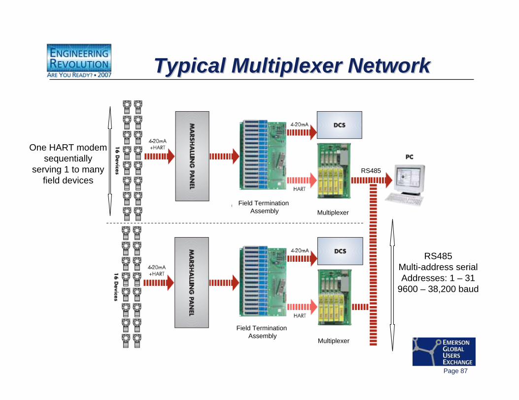
Typical Multiplexer NetworkTypical Multiplexer NetworkTypical Multiplexer Network
Multiplexer
Multiplexer
Field Termination Assembly
Field Termination Assembly
RS485
RS485Multi-address serialAddresses: 1 – 31
9600 – 38,200 baud
One HART modemsequentially
serving 1 to manyfield devices
Page 88
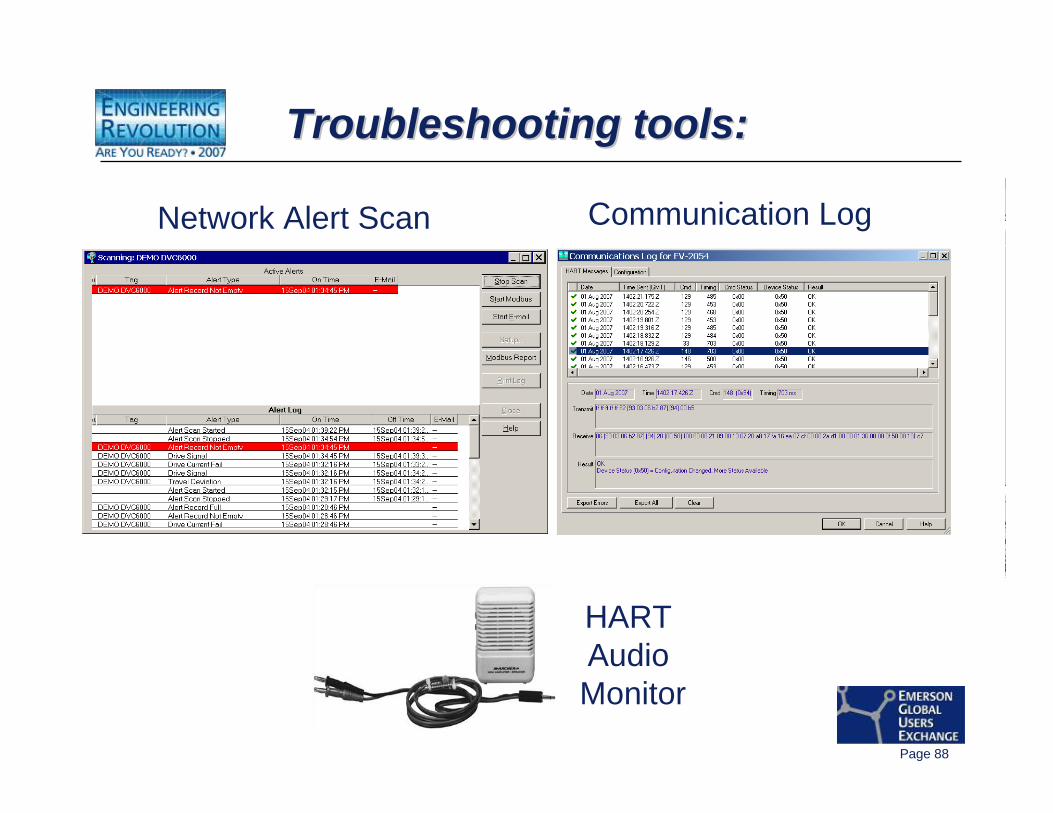
Troubleshooting tools:Troubleshooting tools:Troubleshooting tools:
Network Alert Scan Communication Log
HART Audio Monitor
Page 89
Where to go for more information?Where to go for more information?Where to go for more information?• “DVC6000 Series FIELDVUE® Digital Valve Controller” Instruction Manual,
Form 5647• “FIELDVUE® HF300 Series HART® Filters” Instruction Manual, Form 5715• “Audio Monitor for HART® Communications” Instruction Manual
Supplement, Form 5811• “HART® Field Communication Protocol” Instruction Manual Supplement,
Form 5812• “Using the HART® Tri-Loop™ HART-to-Analog Signal Converter with
FIELDVUE® Digital Valve Controllers” Instruction Manual Supplement, Form 5813
• FIELDVUE Product website: www.FIELDVUE.com• HART Communication Foundation website: www.hartcomm2.org• MTL Instruments website: www.mtl-inst.com• Pepperl & Fuchs (P & F, ELCON) website: www.pepperl-fuchs.com• ARCOM website: www.arcom.com
Page 90
Thank you for attending!!Thank you for attending!!Thank you for attending!!
Questions?


![Installation of Fieldbus - Bachelor of Engineering ...automation.kmitl.ac.th/page/matter/data/Installation Of Fieldbus.pdf · [File Name or Event] Emerson Confidential 27-Jun-01,](https://img.pdfslide.us/doc/110x75/5ab457e77f8b9ab7638b9a57/installation-of-fieldbus-bachelor-of-engineering-of-fieldbuspdffile-name.jpg)