Embed Size (px)
Citation preview
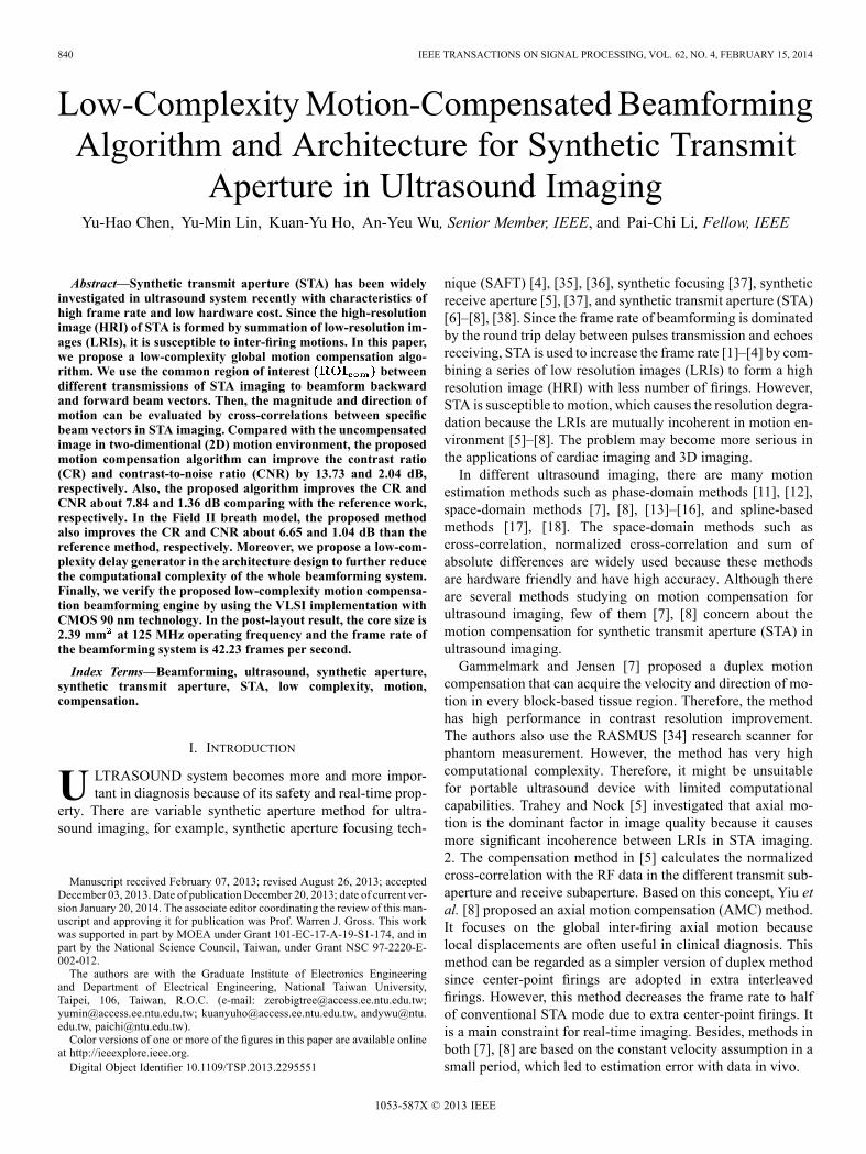
840 IEEE TRANSACTIONS ON SIGNAL PROCESSING, VOL. 62, NO. 4, FEBRUARY 15, 2014
Low-ComplexityMotion-Compensated BeamformingAlgorithm and Architecture for Synthetic Transmit
Aperture in Ultrasound ImagingYu-Hao Chen, Yu-Min Lin, Kuan-Yu Ho, An-Yeu Wu, Senior Member, IEEE, and Pai-Chi Li, Fellow, IEEE
Abstract—Synthetic transmit aperture (STA) has been widelyinvestigated in ultrasound system recently with characteristics ofhigh frame rate and low hardware cost. Since the high-resolutionimage (HRI) of STA is formed by summation of low-resolution im-ages (LRIs), it is susceptible to inter-firing motions. In this paper,we propose a low-complexity global motion compensation algo-rithm. We use the common region of interest betweendifferent transmissions of STA imaging to beamform backwardand forward beam vectors. Then, the magnitude and direction ofmotion can be evaluated by cross-correlations between specificbeam vectors in STA imaging. Compared with the uncompensatedimage in two-dimentional (2D) motion environment, the proposedmotion compensation algorithm can improve the contrast ratio(CR) and contrast-to-noise ratio (CNR) by 13.73 and 2.04 dB,respectively. Also, the proposed algorithm improves the CR andCNR about 7.84 and 1.36 dB comparing with the reference work,respectively. In the Field II breath model, the proposed methodalso improves the CR and CNR about 6.65 and 1.04 dB than thereference method, respectively. Moreover, we propose a low-com-plexity delay generator in the architecture design to further reducethe computational complexity of the whole beamforming system.Finally, we verify the proposed low-complexity motion compensa-tion beamforming engine by using the VLSI implementation withCMOS 90 nm technology. In the post-layout result, the core size is2.39 mm at 125 MHz operating frequency and the frame rate ofthe beamforming system is 42.23 frames per second.
Index Terms—Beamforming, ultrasound, synthetic aperture,synthetic transmit aperture, STA, low complexity, motion,compensation.
I. INTRODUCTION
U LTRASOUND system becomes more and more impor-tant in diagnosis because of its safety and real-time prop-
erty. There are variable synthetic aperture method for ultra-sound imaging, for example, synthetic aperture focusing tech-
Manuscript received February 07, 2013; revised August 26, 2013; acceptedDecember 03, 2013. Date of publication December 20, 2013; date of current ver-sion January 20, 2014. The associate editor coordinating the review of this man-uscript and approving it for publication was Prof. Warren J. Gross. This workwas supported in part by MOEA under Grant 101-EC-17-A-19-S1-174, and inpart by the National Science Council, Taiwan, under Grant NSC 97-2220-E-002-012.The authors are with the Graduate Institute of Electronics Engineering
and Department of Electrical Engineering, National Taiwan University,Taipei, 106, Taiwan, R.O.C. (e-mail: [email protected];[email protected]; [email protected], [email protected], [email protected]).Color versions of one or more of the figures in this paper are available online
at http://ieeexplore.ieee.org.Digital Object Identifier 10.1109/TSP.2013.2295551
nique (SAFT) [4], [35], [36], synthetic focusing [37], syntheticreceive aperture [5], [37], and synthetic transmit aperture (STA)[6]–[8], [38]. Since the frame rate of beamforming is dominatedby the round trip delay between pulses transmission and echoesreceiving, STA is used to increase the frame rate [1]–[4] by com-bining a series of low resolution images (LRIs) to form a highresolution image (HRI) with less number of firings. However,STA is susceptible to motion, which causes the resolution degra-dation because the LRIs are mutually incoherent in motion en-vironment [5]–[8]. The problem may become more serious inthe applications of cardiac imaging and 3D imaging.In different ultrasound imaging, there are many motion
estimation methods such as phase-domain methods [11], [12],space-domain methods [7], [8], [13]–[16], and spline-basedmethods [17], [18]. The space-domain methods such ascross-correlation, normalized cross-correlation and sum ofabsolute differences are widely used because these methodsare hardware friendly and have high accuracy. Although thereare several methods studying on motion compensation forultrasound imaging, few of them [7], [8] concern about themotion compensation for synthetic transmit aperture (STA) inultrasound imaging.Gammelmark and Jensen [7] proposed a duplex motion
compensation that can acquire the velocity and direction of mo-tion in every block-based tissue region. Therefore, the methodhas high performance in contrast resolution improvement.The authors also use the RASMUS [34] research scanner forphantom measurement. However, the method has very highcomputational complexity. Therefore, it might be unsuitablefor portable ultrasound device with limited computationalcapabilities. Trahey and Nock [5] investigated that axial mo-tion is the dominant factor in image quality because it causesmore significant incoherence between LRIs in STA imaging.2. The compensation method in [5] calculates the normalizedcross-correlation with the RF data in the different transmit sub-aperture and receive subaperture. Based on this concept, Yiu etal. [8] proposed an axial motion compensation (AMC) method.It focuses on the global inter-firing axial motion becauselocal displacements are often useful in clinical diagnosis. Thismethod can be regarded as a simpler version of duplex methodsince center-point firings are adopted in extra interleavedfirings. However, this method decreases the frame rate to halfof conventional STA mode due to extra center-point firings. Itis a main constraint for real-time imaging. Besides, methods inboth [7], [8] are based on the constant velocity assumption in asmall period, which led to estimation error with data in vivo.
1053-587X © 2013 IEEE
CHEN et al.: LOW-COMPLEXITY MOTION-COMPENSATED BEAMFORMING ALGORITHM 841
In this work, we propose a low-complexity motion compen-sation algorithm and architecture to improve the correctnessof motion estimation. The proposed algorithms include axialmotion estimation, 2D motion estimation and motion com-pensation method. We use the Common Region of Interest
, which is mentioned in Section III, between differenttransmissions of STA imaging to obtain beamformed backwardand forward beam vectors. Then, we calculate the cross-correla-tion of these beam vectors to estimate the motion displacement.The proposed algorithms reduce computational complexitysignificantly by calculating the normalized cross-correlationbetween beamformed vectors instead of RF data in differentchannels. Moreover, since the computational complexity bot-tleneck in beamforming system is delay generator, we alsopropose a low-complexity delay generator to further reducethe computational complexity. The proposed algorithm andarchitecture have three features:• Use overlapped : Instead of channel data, thebeam vectors obtained from are used to reducethe computational complexity.
• No extra firing : Since there are no extra firing for motionestimation in our proposed algorithm, the proposed algo-rithm is more suitable to be used with non-constant motionvelocity.
• Low-complexity : The geometry property is used in delaygenerator to reduce the computational complexity. Also,the ping-pong buffers are used in motion estimation to readdata and calculate the normalized cross-correlation in par-allel to reduce the computational complexity.
At last, we implement the proposed low-complexity motioncompensated beamforming engine in TSMC CMOS 90 nmtechnology. The core size is 2.39 mm at 125 MHz operatingfrequency.This paper is organized as follows. In Section II, we introduce
the concept of STA imaging and existing works for motion com-pensation. In Section III, we describe our proposed axial mo-tion estimation, 2Dmotion estimation andmotion compensationmethod in STA imaging. The analysis of proposed algorithmand simulation results are presented in Sections IV and V, re-spectively. In Section VI, we describe the architecture design ofthe proposed low-complexity motion compensation algorithmand the proposed low-complexity delay generator. The imple-mentation results and conclusion are presented in Sections VIIand VIII, respectively.
II. STA IMAGING
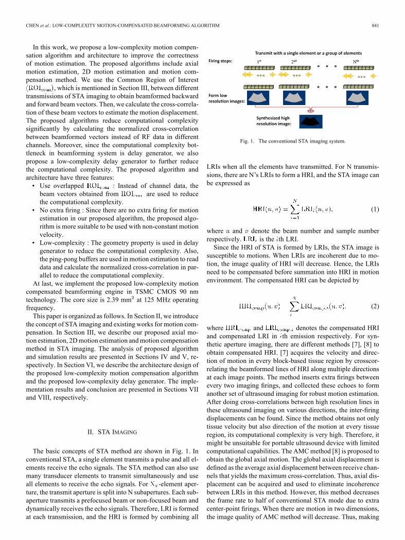
The basic concepts of STA method are shown in Fig. 1. Inconventional STA, a single element transmits a pulse and all el-ements receive the echo signals. The STA method can also usemany transducer elements to transmit simultaneously and useall elements to receive the echo signals. For -element aper-ture, the transmit aperture is split into N subapertures. Each sub-aperture transmits a prefocused beam or non-focused beam anddynamically receives the echo signals. Therefore, LRI is formedat each transmission, and the HRI is formed by combining all
Fig. 1. The conventional STA imaging system.
LRIs when all the elements have transmitted. For N transmis-sions, there are N’s LRIs to form a HRI, and the STA image canbe expressed as
(1)
where and denote the beam number and sample numberrespectively. is the th LRI.Since the HRI of STA is formed by LRIs, the STA image is
susceptible to motions. When LRIs are incoherent due to mo-tion, the image quality of HRI will decrease. Hence, the LRIsneed to be compensated before summation into HRI in motionenvironment. The compensated HRI can be depicted by
(2)
where and denotes the compensated HRIand compensated LRI in th emission respectively. For syn-thetic aperture imaging, there are different methods [7], [8] toobtain compensated HRI. [7] acquires the velocity and direc-tion of motion in every block-based tissue region by crosscor-relating the beamformed lines of HRI along multiple directionsat each image points. The method inserts extra firings betweenevery two imaging firings, and collected these echoes to formanother set of ultrasound imaging for robust motion estimation.After doing cross-correlations between high resolution lines inthese ultrasound imaging on various directions, the inter-firingdisplacements can be found. Since the method obtains not onlytissue velocity but also direction of the motion at every tissueregion, its computational complexity is very high. Therefore, itmight be unsuitable for portable ultrasound device with limitedcomputational capabilities. The AMCmethod [8] is proposed toobtain the global axial motion. The global axial displacement isdefined as the average axial displacement between receive chan-nels that yields the maximum cross-correlation. Thus, axial dis-placement can be acquired and used to eliminate incoherencebetween LRIs in this method. However, this method decreasesthe frame rate to half of conventional STA mode due to extracenter-point firings. When there are motion in two dimensions,the image quality of AMC method will decrease. Thus, making
842 IEEE TRANSACTIONS ON SIGNAL PROCESSING, VOL. 62, NO. 4, FEBRUARY 15, 2014
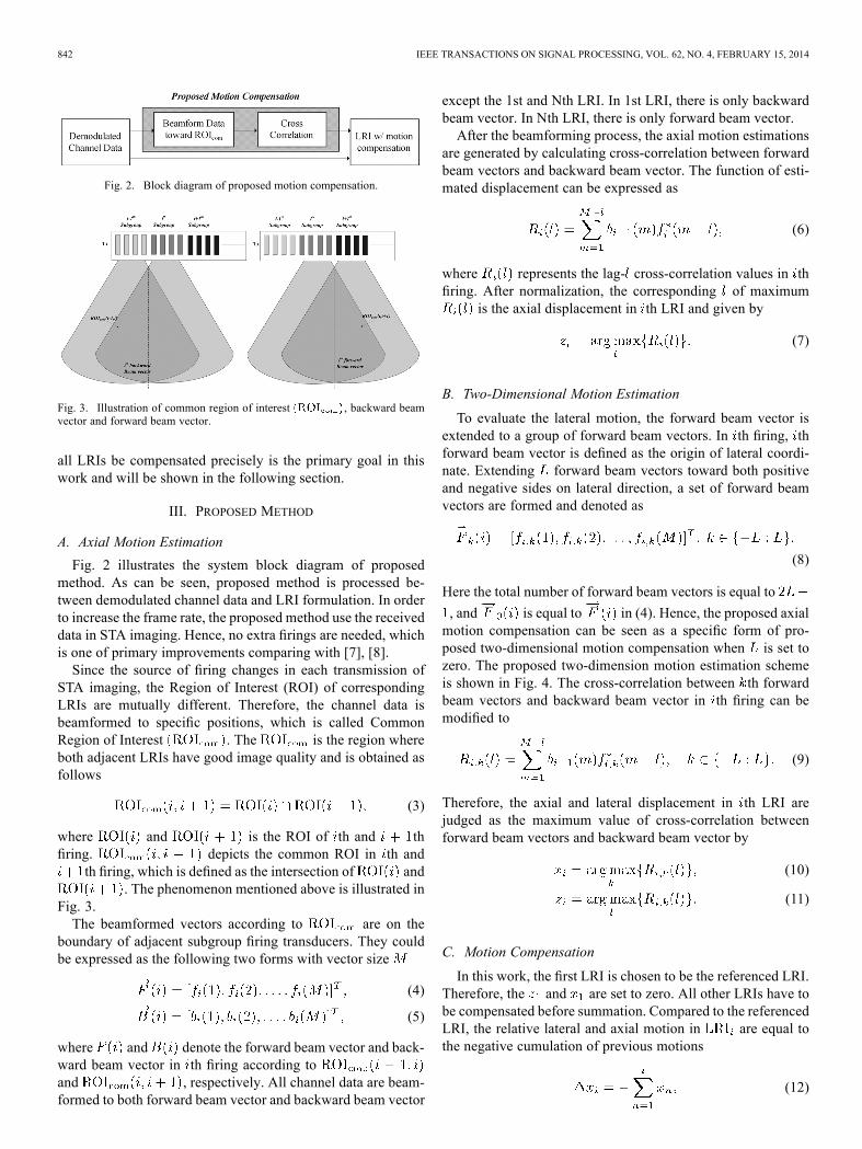
Fig. 2. Block diagram of proposed motion compensation.
Fig. 3. Illustration of common region of interest , backward beamvector and forward beam vector.
all LRIs be compensated precisely is the primary goal in thiswork and will be shown in the following section.
III. PROPOSED METHOD
A. Axial Motion Estimation
Fig. 2 illustrates the system block diagram of proposedmethod. As can be seen, proposed method is processed be-tween demodulated channel data and LRI formulation. In orderto increase the frame rate, the proposed method use the receiveddata in STA imaging. Hence, no extra firings are needed, whichis one of primary improvements comparing with [7], [8].Since the source of firing changes in each transmission of
STA imaging, the Region of Interest (ROI) of correspondingLRIs are mutually different. Therefore, the channel data isbeamformed to specific positions, which is called CommonRegion of Interest . The is the region whereboth adjacent LRIs have good image quality and is obtained asfollows
(3)
where and is the ROI of th and thfiring. depicts the common ROI in th and
th firing, which is defined as the intersection of and. The phenomenon mentioned above is illustrated in
Fig. 3.The beamformed vectors according to are on the
boundary of adjacent subgroup firing transducers. They couldbe expressed as the following two forms with vector size
(4)
(5)
where and denote the forward beam vector and back-ward beam vector in th firing according toand , respectively. All channel data are beam-formed to both forward beam vector and backward beam vector
except the 1st and Nth LRI. In 1st LRI, there is only backwardbeam vector. In Nth LRI, there is only forward beam vector.After the beamforming process, the axial motion estimations
are generated by calculating cross-correlation between forwardbeam vectors and backward beam vector. The function of esti-mated displacement can be expressed as
(6)
where represents the lag- cross-correlation values in thfiring. After normalization, the corresponding of maximum
is the axial displacement in th LRI and given by
(7)
B. Two-Dimensional Motion Estimation
To evaluate the lateral motion, the forward beam vector isextended to a group of forward beam vectors. In th firing, thforward beam vector is defined as the origin of lateral coordi-nate. Extending forward beam vectors toward both positiveand negative sides on lateral direction, a set of forward beamvectors are formed and denoted as
(8)
Here the total number of forward beam vectors is equal to
, and is equal to in (4). Hence, the proposed axialmotion compensation can be seen as a specific form of pro-posed two-dimensional motion compensation when is set tozero. The proposed two-dimension motion estimation schemeis shown in Fig. 4. The cross-correlation between th forwardbeam vectors and backward beam vector in th firing can bemodified to
(9)
Therefore, the axial and lateral displacement in th LRI arejudged as the maximum value of cross-correlation betweenforward beam vectors and backward beam vector by
(10)
(11)
C. Motion Compensation
In this work, the first LRI is chosen to be the referenced LRI.Therefore, the and are set to zero. All other LRIs have tobe compensated before summation. Compared to the referencedLRI, the relative lateral and axial motion in are equal tothe negative cumulation of previous motions
(12)
CHEN et al.: LOW-COMPLEXITY MOTION-COMPENSATED BEAMFORMING ALGORITHM 843
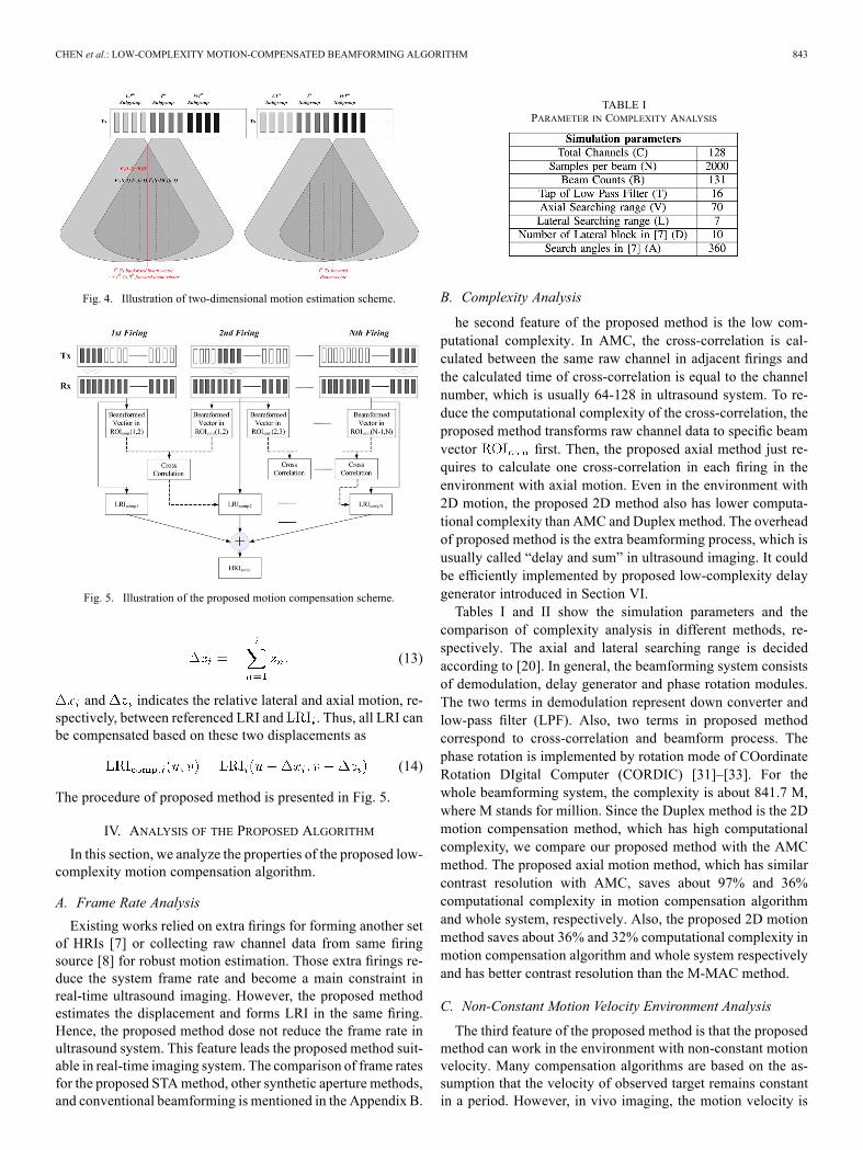
Fig. 4. Illustration of two-dimensional motion estimation scheme.
Fig. 5. Illustration of the proposed motion compensation scheme.
(13)
and indicates the relative lateral and axial motion, re-spectively, between referenced LRI and . Thus, all LRI canbe compensated based on these two displacements as
(14)
The procedure of proposed method is presented in Fig. 5.
IV. ANALYSIS OF THE PROPOSED ALGORITHM
In this section, we analyze the properties of the proposed low-complexity motion compensation algorithm.
A. Frame Rate Analysis
Existing works relied on extra firings for forming another setof HRIs [7] or collecting raw channel data from same firingsource [8] for robust motion estimation. Those extra firings re-duce the system frame rate and become a main constraint inreal-time ultrasound imaging. However, the proposed methodestimates the displacement and forms LRI in the same firing.Hence, the proposed method dose not reduce the frame rate inultrasound system. This feature leads the proposed method suit-able in real-time imaging system. The comparison of frame ratesfor the proposed STAmethod, other synthetic aperture methods,and conventional beamforming is mentioned in the Appendix B.
TABLE IPARAMETER IN COMPLEXITY ANALYSIS
B. Complexity Analysis
he second feature of the proposed method is the low com-putational complexity. In AMC, the cross-correlation is cal-culated between the same raw channel in adjacent firings andthe calculated time of cross-correlation is equal to the channelnumber, which is usually 64-128 in ultrasound system. To re-duce the computational complexity of the cross-correlation, theproposed method transforms raw channel data to specific beamvector first. Then, the proposed axial method just re-quires to calculate one cross-correlation in each firing in theenvironment with axial motion. Even in the environment with2D motion, the proposed 2D method also has lower computa-tional complexity than AMC and Duplex method. The overheadof proposed method is the extra beamforming process, which isusually called “delay and sum” in ultrasound imaging. It couldbe efficiently implemented by proposed low-complexity delaygenerator introduced in Section VI.Tables I and II show the simulation parameters and the
comparison of complexity analysis in different methods, re-spectively. The axial and lateral searching range is decidedaccording to [20]. In general, the beamforming system consistsof demodulation, delay generator and phase rotation modules.The two terms in demodulation represent down converter andlow-pass filter (LPF). Also, two terms in proposed methodcorrespond to cross-correlation and beamform process. Thephase rotation is implemented by rotation mode of COordinateRotation DIgital Computer (CORDIC) [31]–[33]. For thewhole beamforming system, the complexity is about 841.7 M,where M stands for million. Since the Duplex method is the 2Dmotion compensation method, which has high computationalcomplexity, we compare our proposed method with the AMCmethod. The proposed axial motion method, which has similarcontrast resolution with AMC, saves about 97% and 36%computational complexity in motion compensation algorithmand whole system, respectively. Also, the proposed 2D motionmethod saves about 36% and 32% computational complexity inmotion compensation algorithm and whole system respectivelyand has better contrast resolution than the M-MAC method.
C. Non-Constant Motion Velocity Environment Analysis
The third feature of the proposed method is that the proposedmethod can work in the environment with non-constant motionvelocity. Many compensation algorithms are based on the as-sumption that the velocity of observed target remains constantin a period. However, in vivo imaging, the motion velocity is
844 IEEE TRANSACTIONS ON SIGNAL PROCESSING, VOL. 62, NO. 4, FEBRUARY 15, 2014
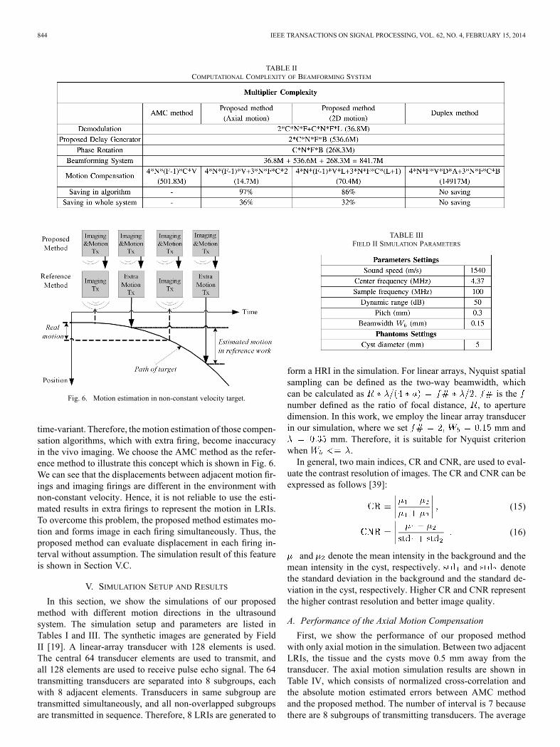
TABLE IICOMPUTATIONAL COMPLEXITY OF BEAMFORMING SYSTEM
Fig. 6. Motion estimation in non-constant velocity target.
time-variant. Therefore, the motion estimation of those compen-sation algorithms, which with extra firing, become inaccuracyin the vivo imaging. We choose the AMC method as the refer-ence method to illustrate this concept which is shown in Fig. 6.We can see that the displacements between adjacent motion fir-ings and imaging firings are different in the environment withnon-constant velocity. Hence, it is not reliable to use the esti-mated results in extra firings to represent the motion in LRIs.To overcome this problem, the proposed method estimates mo-tion and forms image in each firing simultaneously. Thus, theproposed method can evaluate displacement in each firing in-terval without assumption. The simulation result of this featureis shown in Section V.C.
V. SIMULATION SETUP AND RESULTS
In this section, we show the simulations of our proposedmethod with different motion directions in the ultrasoundsystem. The simulation setup and parameters are listed inTables I and III. The synthetic images are generated by FieldII [19]. A linear-array transducer with 128 elements is used.The central 64 transducer elements are used to transmit, andall 128 elements are used to receive pulse echo signal. The 64transmitting transducers are separated into 8 subgroups, eachwith 8 adjacent elements. Transducers in same subgroup aretransmitted simultaneously, and all non-overlapped subgroupsare transmitted in sequence. Therefore, 8 LRIs are generated to
TABLE IIIFIELD II SIMULATION PARAMETERS
form a HRI in the simulation. For linear arrays, Nyquist spatialsampling can be defined as the two-way beamwidth, whichcan be calculated as . is thenumber defined as the ratio of focal distance, , to aperturedimension. In this work, we employ the linear array transducerin our simulation, where we set mm and
mm. Therefore, it is suitable for Nyquist criterionwhen .In general, two main indices, CR and CNR, are used to eval-
uate the contrast resolution of images. The CR and CNR can beexpressed as follows [39]:
(15)
(16)
and denote the mean intensity in the background and themean intensity in the cyst, respectively. and denotethe standard deviation in the background and the standard de-viation in the cyst, respectively. Higher CR and CNR representthe higher contrast resolution and better image quality.
A. Performance of the Axial Motion Compensation
First, we show the performance of our proposed methodwith only axial motion in the simulation. Between two adjacentLRIs, the tissue and the cysts move 0.5 mm away from thetransducer. The axial motion simulation results are shown inTable IV, which consists of normalized cross-correlation andthe absolute motion estimated errors between AMC methodand the proposed method. The number of interval is 7 becausethere are 8 subgroups of transmitting transducers. The average
CHEN et al.: LOW-COMPLEXITY MOTION-COMPENSATED BEAMFORMING ALGORITHM 845
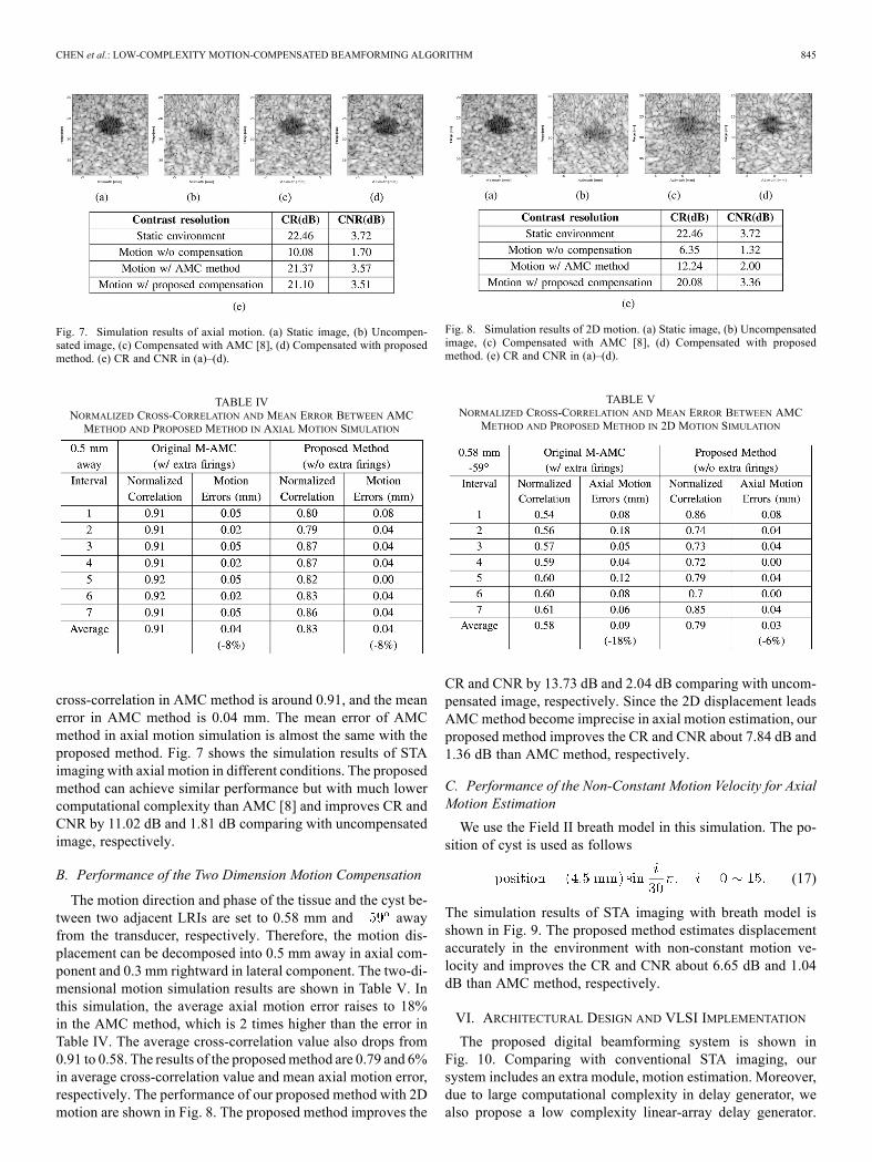
Fig. 7. Simulation results of axial motion. (a) Static image, (b) Uncompen-sated image, (c) Compensated with AMC [8], (d) Compensated with proposedmethod. (e) CR and CNR in (a)–(d).
TABLE IVNORMALIZED CROSS-CORRELATION AND MEAN ERROR BETWEEN AMCMETHOD AND PROPOSED METHOD IN AXIAL MOTION SIMULATION
cross-correlation in AMC method is around 0.91, and the meanerror in AMC method is 0.04 mm. The mean error of AMCmethod in axial motion simulation is almost the same with theproposed method. Fig. 7 shows the simulation results of STAimaging with axial motion in different conditions. The proposedmethod can achieve similar performance but with much lowercomputational complexity than AMC [8] and improves CR andCNR by 11.02 dB and 1.81 dB comparing with uncompensatedimage, respectively.
B. Performance of the Two Dimension Motion Compensation
The motion direction and phase of the tissue and the cyst be-tween two adjacent LRIs are set to 0.58 mm and awayfrom the transducer, respectively. Therefore, the motion dis-placement can be decomposed into 0.5 mm away in axial com-ponent and 0.3 mm rightward in lateral component. The two-di-mensional motion simulation results are shown in Table V. Inthis simulation, the average axial motion error raises to 18%in the AMC method, which is 2 times higher than the error inTable IV. The average cross-correlation value also drops from0.91 to 0.58. The results of the proposedmethod are 0.79 and 6%in average cross-correlation value and mean axial motion error,respectively. The performance of our proposed method with 2Dmotion are shown in Fig. 8. The proposed method improves the
Fig. 8. Simulation results of 2D motion. (a) Static image, (b) Uncompensatedimage, (c) Compensated with AMC [8], (d) Compensated with proposedmethod. (e) CR and CNR in (a)–(d).
TABLE VNORMALIZED CROSS-CORRELATION AND MEAN ERROR BETWEEN AMC
METHOD AND PROPOSED METHOD IN 2D MOTION SIMULATION
CR and CNR by 13.73 dB and 2.04 dB comparing with uncom-pensated image, respectively. Since the 2D displacement leadsAMCmethod become imprecise in axial motion estimation, ourproposed method improves the CR and CNR about 7.84 dB and1.36 dB than AMC method, respectively.
C. Performance of the Non-Constant Motion Velocity for AxialMotion Estimation
We use the Field II breath model in this simulation. The po-sition of cyst is used as follows
(17)
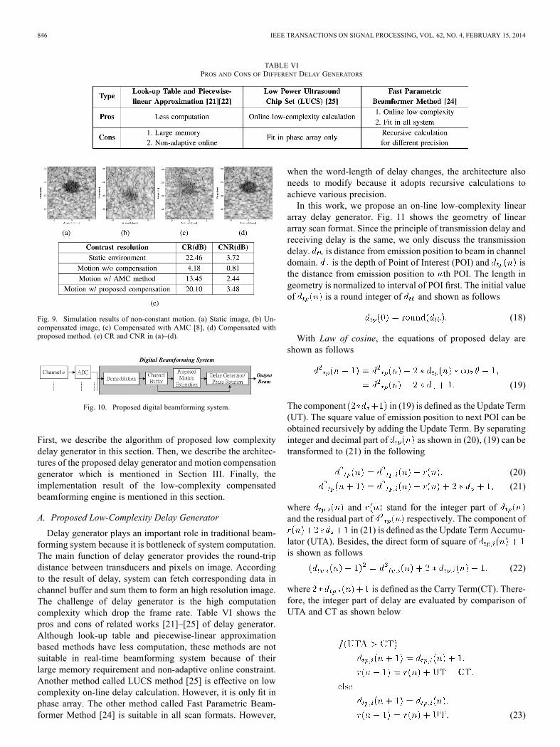
The simulation results of STA imaging with breath model isshown in Fig. 9. The proposed method estimates displacementaccurately in the environment with non-constant motion ve-locity and improves the CR and CNR about 6.65 dB and 1.04dB than AMC method, respectively.
VI. ARCHITECTURAL DESIGN AND VLSI IMPLEMENTATION
The proposed digital beamforming system is shown inFig. 10. Comparing with conventional STA imaging, oursystem includes an extra module, motion estimation. Moreover,due to large computational complexity in delay generator, wealso propose a low complexity linear-array delay generator.
846 IEEE TRANSACTIONS ON SIGNAL PROCESSING, VOL. 62, NO. 4, FEBRUARY 15, 2014
TABLE VIPROS AND CONS OF DIFFERENT DELAY GENERATORS
Fig. 9. Simulation results of non-constant motion. (a) Static image, (b) Un-compensated image, (c) Compensated with AMC [8], (d) Compensated withproposed method. (e) CR and CNR in (a)–(d).
Fig. 10. Proposed digital beamforming system.
First, we describe the algorithm of proposed low complexitydelay generator in this section. Then, we describe the architec-tures of the proposed delay generator and motion compensationgenerator which is mentioned in Section III. Finally, theimplementation result of the low-complexity compensatedbeamforming engine is mentioned in this section.
A. Proposed Low-Complexity Delay Generator
Delay generator plays an important role in traditional beam-forming system because it is bottleneck of system computation.The main function of delay generator provides the round-tripdistance between transducers and pixels on image. Accordingto the result of delay, system can fetch corresponding data inchannel buffer and sum them to form an high resolution image.The challenge of delay generator is the high computationcomplexity which drop the frame rate. Table VI shows thepros and cons of related works [21]–[25] of delay generator.Although look-up table and piecewise-linear approximationbased methods have less computation, these methods are notsuitable in real-time beamforming system because of theirlarge memory requirement and non-adaptive online constraint.Another method called LUCS method [25] is effective on lowcomplexity on-line delay calculation. However, it is only fit inphase array. The other method called Fast Parametric Beam-former Method [24] is suitable in all scan formats. However,
when the word-length of delay changes, the architecture alsoneeds to modify because it adopts recursive calculations toachieve various precision.In this work, we propose an on-line low-complexity linear
array delay generator. Fig. 11 shows the geometry of lineararray scan format. Since the principle of transmission delay andreceiving delay is the same, we only discuss the transmissiondelay. is distance from emission position to beam in channeldomain. is the depth of Point of Interest (POI) and isthe distance from emission position to th POI. The length ingeometry is normalized to interval of POI first. The initial valueof is a round integer of and shown as follows
(18)
With Law of cosine, the equations of proposed delay areshown as follows
(19)
The component in (19) is defined as the Update Term(UT). The square value of emission position to next POI can beobtained recursively by adding the Update Term. By separatinginteger and decimal part of as shown in (20), (19) can betransformed to (21) in the following
(20)
(21)
where and stand for the integer part ofand the residual part of respectively. The component of
in (21) is defined as the Update Term Accumu-lator (UTA). Besides, the direct form of square ofis shown as follows
(22)
where is defined as the Carry Term(CT). There-fore, the integer part of delay are evaluated by comparison ofUTA and CT as shown below
(23)
CHEN et al.: LOW-COMPLEXITY MOTION-COMPENSATED BEAMFORMING ALGORITHM 847
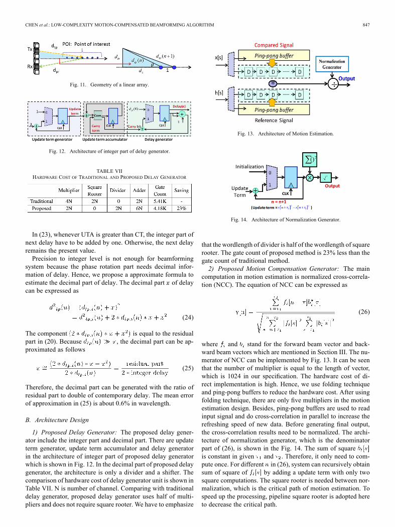
Fig. 11. Geometry of a linear array.
Fig. 12. Architecture of integer part of delay generator.
TABLE VIIHARDWARE COST OF TRADITIONAL AND PROPOSED DELAY GENERATOR
In (23), whenever UTA is greater than CT, the integer part ofnext delay have to be added by one. Otherwise, the next delayremains the present value.Precision to integer level is not enough for beamforming
system because the phase rotation part needs decimal infor-mation of delay. Hence, we propose a approximate formula toestimate the decimal part of delay. The decimal part of delaycan be expressed as
(24)
The component is equal to the residualpart in (20). Because , the decimal part can be ap-proximated as follows
(25)
Therefore, the decimal part can be generated with the ratio ofresidual part to double of contemporary delay. The mean errorof approximation in (25) is about 0.6% in wavelength.
B. Architecture Design
1) Proposed Delay Generator: The proposed delay gener-ator include the integer part and decimal part. There are updateterm generator, update term accumulator and delay generatorin the architecture of integer part of proposed delay generatorwhich is shown in Fig. 12. In the decimal part of proposed delaygenerator, the architecture is only a divider and a shifter. Thecomparison of hardware cost of delay generator unit is shown inTable VII. N is number of channel. Comparing with traditionaldelay generator, proposed delay generator uses half of multi-pliers and does not require square rooter. We have to emphasize
Fig. 13. Architecture of Motion Estimation.
Fig. 14. Architecture of Normalization Generator.
that the wordlength of divider is half of the wordlength of squarerooter. The gate count of proposed method is 23% less than thegate count of traditional method.2) Proposed Motion Compensation Generator: The main
computation in motion estimation is normalized cross-correla-tion (NCC). The equation of NCC can be expressed as
(26)
where and stand for the forward beam vector and back-ward beam vectors which are mentioned in Section III. The nu-merator of NCC can be implemented by Fig. 13. It can be seenthat the number of multiplier is equal to the length of vector,which is 1024 in our specification. The hardware cost of di-rect implementation is high. Hence, we use folding techniqueand ping-pong buffers to reduce the hardware cost. After usingfolding technique, there are only five multipliers in the motionestimation design. Besides, ping-pong buffers are used to readinput signal and do cross-correlation in parallel to increase therefreshing speed of new data. Before generating final output,the cross-correlation results need to be normalized. The archi-tecture of normalization generator, which is the denominatorpart of (26), is shown in the Fig. 14. The sum of squareis constant in given and . Therefore, it only need to com-pute once. For different in (26), system can recursively obtainsum of square of by adding a update term with only twosquare computations. The square rooter is needed between nor-malization, which is the critical path of motion estimation. Tospeed up the processing, pipeline square rooter is adopted hereto decrease the critical path.
848 IEEE TRANSACTIONS ON SIGNAL PROCESSING, VOL. 62, NO. 4, FEBRUARY 15, 2014
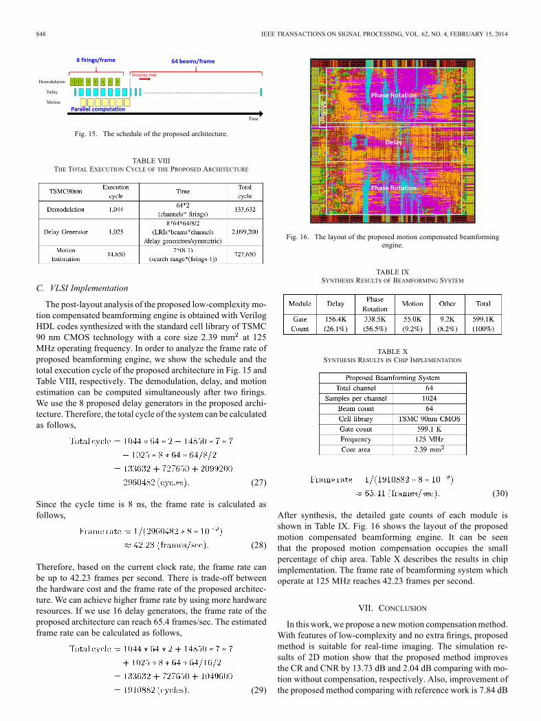
Fig. 15. The schedule of the proposed architecture.
TABLE VIIITHE TOTAL EXECUTION CYCLE OF THE PROPOSED ARCHITECTURE
C. VLSI Implementation
The post-layout analysis of the proposed low-complexity mo-tion compensated beamforming engine is obtained with VerilogHDL codes synthesized with the standard cell library of TSMC90 nm CMOS technology with a core size 2.39 mm at 125MHz operating frequency. In order to analyze the frame rate ofproposed beamforming engine, we show the schedule and thetotal execution cycle of the proposed architecture in Fig. 15 andTable VIII, respectively. The demodulation, delay, and motionestimation can be computed simultaneously after two firings.We use the 8 proposed delay generators in the proposed archi-tecture. Therefore, the total cycle of the system can be calculatedas follows,
(27)
Since the cycle time is 8 ns, the frame rate is calculated asfollows,
(28)
Therefore, based on the current clock rate, the frame rate canbe up to 42.23 frames per second. There is trade-off betweenthe hardware cost and the frame rate of the proposed architec-ture. We can achieve higher frame rate by using more hardwareresources. If we use 16 delay generators, the frame rate of theproposed architecture can reach 65.4 frames/sec. The estimatedframe rate can be calculated as follows,
(29)
Fig. 16. The layout of the proposed motion compensated beamformingengine.
TABLE IXSYNTHESIS RESULTS OF BEAMFORMING SYSTEM
TABLE XSYNTHESIS RESULTS IN CHIP IMPLEMENTATION
(30)
After synthesis, the detailed gate counts of each module isshown in Table IX. Fig. 16 shows the layout of the proposedmotion compensated beamforming engine. It can be seenthat the proposed motion compensation occupies the smallpercentage of chip area. Table X describes the results in chipimplementation. The frame rate of beamforming system whichoperate at 125 MHz reaches 42.23 frames per second.
VII. CONCLUSION
In this work, we propose a newmotion compensationmethod.With features of low-complexity and no extra firings, proposedmethod is suitable for real-time imaging. The simulation re-sults of 2D motion show that the proposed method improvesthe CR and CNR by 13.73 dB and 2.04 dB comparing with mo-tion without compensation, respectively. Also, improvement ofthe proposed method comparing with reference work is 7.84 dB
CHEN et al.: LOW-COMPLEXITY MOTION-COMPENSATED BEAMFORMING ALGORITHM 849
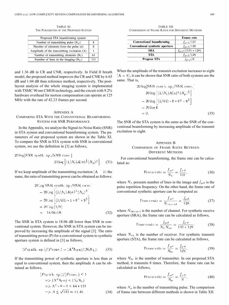
TABLE XITHE PARAMETER OF THE PROPOSED SYSTEM
and 1.36 dB in CR and CNR, respectively. In Field II breathmodel, the proposed method improves the CR and CNR by 6.65dB and 1.04 dB than reference method, respectively. The post-layout analysis of the whole imaging system is implementedwith TSMC 90 nm CMOS technology, and the circuit with 9.2%hardware overhead for motion compensation can operate at 125MHz with the rate of 42.23 frames per second.
APPENDIX ACOMPARING STA WITH THE CONVENTIONAL BEAMFORMING
SYSTEM FOR SNR PERFORMANCE
In the Appendix, we analyze the Signal-to-Noise Ratio (SNR)in STA system and conventional beamforming system. The pa-rameters of our proposed system are shown in the Table XI.To compare the SNR in STA system with SNR in conventionalsystem, we use the definition in [3] as follows,
(31)
If we keep amplitude of the transmitting excitation thesame, the ratio of transmitting power can be obtained as follows:
(32)
The SNR in STA system is 18.06 dB lower than SNR in con-ventional system. However, the SNR in STA system can be im-proved by increasing the amplitude of the signal [3]. The ratioof transmitting power (P) for a conventional system to syntheticaperture system is defined in [3] as follows,
(33)
If the transmitting power of synthetic aperture is less than orequal to conventional system, then the amplitude A can be ob-tained as follows,
(34)
TABLE XIICOMPARISON OF FRAME RATES FOR DIFFERENT METHODS
When the amplitude of the transmit excitation increases to eight, it can be shown that SNR ratio of both systems are the
same. That is,
(35)
The SNR of the STA system is the same as the SNR of the con-ventional beamforming by increasing amplitude of the transmitexcitation to eight.
APPENDIX BCOMPARISON OF FRAME RATES BETWEEN
DIFFERENT METHODS
For conventional beamforming, the frame rate can be calcu-lated as:
(36)
where presents number of lines in the image and is thepulse repetition frequency. On the other hand, the frame rate ofconventional synthetic aperture can be computed as:
(37)
where is the number of channel. For synthetic receiveaperture (SRA), the frame rate can be calculated as follows,
(38)
where is the number of receiver. For synthetic transmitaperture (STA), the frame rate can be calculated as follows,
(39)
where is the number of transmitter. In our proposed STAmethod, it transmits 8 times. Therefore, the frame rate can becalculated as follows,
(40)
where is the number of transmitting pulse. The comparisonof frame rate between different methods is shown in Table XII.
850 IEEE TRANSACTIONS ON SIGNAL PROCESSING, VOL. 62, NO. 4, FEBRUARY 15, 2014
The proposed STA method has highest frame rate comparingwith other methods.
REFERENCES
[1] S. Holm and H. Yao, “Method and apparatus for synthetic transmitaperture imaging,” U.S. Patent 5 951 479, Sep. 14, 1999.
[2] D. P. Shattuck, M. D. Weinshenker, S. W. Smith, and O. T. von Ramm,“Explososcan: A parallel processing technique for high speed ultra-sound imaging with linear phased arrays,” J. Acoust. Soc. Amer., vol.75, no. 4, pp. 1273–1282, Apr. 1984.
[3] G. R. Lockwood, J. R. Talman, and S. S. Brunke, “Real-time 3-D ul-trasound imaging using sparse synthetic aperture beamforming,” IEEETrans. Ultrason., Ferroelectr., Freq. Control, vol. 45, pp. 980–988,1998.
[4] M. Karaman, P. C. Li, and M. O’Donnell, “Synthetic aperture imagingfor small scale systems,” IEEE Trans. Ultrason., Ferroelectr.,, Freq.Control, vol. 42, pp. 429–442, 1995.
[5] G. E. Trahey and L. F. Nock, “Synthetic receive aperture imaging withphase correction for motion and for tissue inhomogeneities. Part II: Ef-fects of and correction formotion,” IEEE Trans. Ultrason. Ferroelectr.,Freq. Control, vol. 39, pp. 496–501, 1992.
[6] C. R. Hazard and G. R. Lockwood, “Effects of motion on a syntheticaperture beamformer for real-time 3D ultrasound,” in Proc. IEEE Ul-trason. Symp., 1999, pp. 1221–1224.
[7] K. L. Gammelmark and J. A. Jensen, “Duplex synthetic apertureimaging with tissue motion compensation,” in Proc. IEEE Ultrason.Symp., 2003, pp. 1569–1573.
[8] B. Y. S. Yiu, I. K. H. Tsang, and A. C. H. Yu, “A modified syntheticaperture imaging approach with axial motion compensation,” in IEEEUltrason. Symp., Nov. 2–5, 2008, p. 1254, 1257.
[9] Y. H. Chen, K. Y. Ho, and A. Y. Wu, “Coherent image herding ofinhomogeneous motion compensation for synthetic transmit aperturein ultrasound image,” in Proc. IEEE Workshop Signal Process. Syst.(SiPS), Oct. 2012, pp. 254–257.
[10] K. Y. Ho, Y. H. Chen, C. Z. Zhan, and A. Y. Wu, “VLSI implemen-tation of real-time motion compensation beamforming in synthetictransmit aperture imaging,” in Proc. IEEE Int. Symp. Circuits Syst.(ISCAS), May 19–23, 2013, p. 1893, 1896.
[11] T. Loupas, R. B. Peterson, and R. W. Gill, “Experimental evaluation ofvelocity and power estimation for ultrasound blood-flow imaging, bymeans of a 2-dimensional autocorrelation approach,” IEEE Trans. Ul-trason., Ferroelectr., Freq. Control, vol. 42, no. 4, pp. 689–699, 1995.
[12] C. Kasai, “Real-time two-dimensional blood-flow imaging using anautocorrelation technique,” IEEE Trans. Ultrason., Ferroelectr., Freq.Control, vol. 33, no. 1, p. 94, 1986.
[13] F. Viola and W. F. Walker, “A comparison of the performance of time-delay estimators in medical ultrasound,” IEEE Trans. Ultrason., Fer-roelectr., Freq. Control, vol. 50, no. 4, pp. 392–401, 2003.
[14] S. Langeland, J. D’hooge, H. Torp, B. Bijnens, and P. Suetens, “Com-parison of time-domain displacement estimators for two-dimensionalRF tracking,” Ultrasound Med. Biol., vol. 29, no. 8, pp. 1177–1186,2003.
[15] R. Z. Azar and S. E. Salcudean, “Motioin estimation in ultrasound im-ages using time domain cross correlation with prior estimation,” IEEETrans. Biomed. Eng., vol. 53, no. 10, pp. 1990–2000, 2006.
[16] A. Basarab, P. Gueth, H. Liebgott, and P. Delachartre, “Phase-basedblock matching applied to motion estimation with unconventionalbeamforming strategies,” Ultrasound Med. Biol., vol. 56, no. 5, pp.945–957, 2009.
[17] F. Viola and W. F. Walker, “A spline-based algorithm for continuoustime-delay estimation using sampled data,” IEEE Trans. Ultrason.,Ferroelectr., Freq. Control, vol. 52, no. 1, pp. 80–93, 2005.
[18] G. F. Pinton and G. E. Trahey, “Continuous delay estimation with poly-nomial splines,” IEEE Trans. Ultrason., . Ferroelectr., Freq. Control,vol. 53, no. 11, pp. 2026–2035, 2006.
[19] J. A. Jensen, “Field: A program for simulating ultrasound systems,”Med. Biologic. Eng. Comput., vol. 34, pp. 351–353, 1996.
[20] J. S. Jeong, J. S. Hwang, M. H. Bae, and T. K. Song, “Effects andlimitations of motion compensation in synthetic aoerture techniques,”in Proc. IEEE Ultrason. Symp., Oct. 2000, vol. 2, p. 1759, 1762.
[21] A. Kassem, J. Wang, A. Khouas, M. Sawan, S. Tabikh, and M.Boukadoum, “Variable delay CMOS implementation for ultrasonicbeamforming,” in Proc. 14th Int. Conf. Microelectron., Dec. 11–13,2002, p. 127, 130.
[22] B. G. Tomov and J. A. Jensen, “Delay generationmethods with reducedmemory requirements,” in Proc. SPIE Conf. Med. Imag., 2003, vol.5035, pp. 491–500.
[23] S. I. Nikolov et al., “Recursive delay calculation unit for parametricbeamformer,” in Proc. SPIE Conf. Med. Imag., 2006, vol. 6147, pp.61470D1–61470D12.
[24] S. I. Nikolov and J. A. Jensen, “Fast parametric beamformer for syn-thetic aperture imaging,” IEEE Trans. Ultrason., Ferroelectr., Freq.Control, vol. 55, no. 8, pp. 1755–1767, 2008.
[25] H. T. Feldkamper et al., “Low power delay calculation for digital beam-forming in handheld ultrasound systems,” in Proc. IEEE Int. Ultrason.,Symp., Oct. 2000, vol. 2, pp. 1763–1766.
[26] K. E. Thomenius, “Evolution of ultrasound beamformers,” in Proc.IEEE Ultrason. Symp., 1996, vol. 2, pp. 1615–1621.
[27] D. K. Peterson and G. S. Kino, “Real-time digital image reconstruction:A description of imaging hardware and an analysis of quantization er-rors,” IEEE Trans. Sonics Ultrason., pp. 337–351, 1984.
[28] K. Jeon, M. H. Bae, S. B. Park, and S. D. Kim, “An efficient real timefocusing delay calculation in ultrasonic imaging systems,” Ultrason.Imag., vol. 16, pp. 231–248, 1994.
[29] B. G. Tomov and J. A. Jensen, “A new architecture for a single-chipmulti-channel beamformer based on a standard FPGA,” in Proc. IEEEUltrason. Symp., 2001, pp. 1529–1533.
[30] S. Holm and K. Kristoffersen, “Analysis of worst-case phase quantiza-tion sidelobes in focused beamforming,” IEEE Trans. Ultrason., Fer-roelectr., Freq. Control, vol. 39, pp. 593–599, 1992.
[31] C. H. Lin and A. Y. Wu, “Mixed-scaling-rotation CORDIC(MSR-CORDIC) algorithm and architecture for scaling-free high-per-formance rotational operations,” IEEE Trans. Circuits Syst. I, Reg.Papers, vol. 52, no. 11, pp. 2385–2396, Nov. 2005.
[32] A. Y. Wu and C. S. Wu, “A unified view for vector rotational CORDICalgorithms and architectures based on angle quantization approach,”IEEE Trans. Circuits Syst. I, Fund. Theory Appl., vol. 49, no. 10, pp.1442–1456, Oct. 2002.
[33] C. S. Wu, A. Y. Wu, and C. H. Lin, “A high-performance/low-latencyvector rotational CORDIC architecture based on extended elementaryangle set and trellis-based searching schemes,” IEEE Trans. CircuitsSyst. II, Analog Digit. Signal Process., vol. 50, no. 9, pp. 589–601,Sep. 2003.
[34] J. A. Jensen, O. Holm, L. J. Jensen, H. Bendsen, H. M. Pedersen, K. Sa-lomonsen, J. Hansen, and S. Nikolov, “Experimental ultrasound systemfor real-time synthetic imaging,” in Proc. IEEE Ultrason. Symp., 1999,vol. 2, pp. 1595–1599.
[35] R. Thomson, “Transverse and longitudinal resolution of the syntheticaperture focusing technique,” Ultrasonics, pp. 9–15, 1984.
[36] M. O’Donnell and L. J. Thomas, “Efficient synthetic aperture imagingfrom a circular apertur with possible application to catheter-basedimaging,” IEEE Trans. Ultrason., Ferroelectr., Freq. Control, vol. 39,pp. 366–380, 1992.
[37] G. E. Trahey and L. F. Nock, “Synthetic receive aperture imaging withphase correction for motion and for tissue inhomogeneities—Part 1:Basic principles,” IEEE Trans. Ultrason., Ferroelect., Freq. Contr.,vol. 39, pp. 489–495, 1992.
[38] S. Holm and H. Yao, “Improved framerate with synthetic transmit aper-ture imaging using prefocused subapertures,” in Proc. IEEE Ultrason.Symp., Oct. 1997, vol. 2, pp. 1535–1538.
[39] P.-C. Li and M.-J. Chen, “Strain compounding: A new approach forspeckle reduction,” IEEE Trans. Ultrason., Ferroelectr., Freq. Control,vol. 49, no. 1, pp. 39–46, Jan. 2002.
Yu-Hao Chen received the B.S. degree in electronicsengineering from National Chiao Tung University,Hsinchu, Taiwan, in 2009. He is currently workingtoward the Ph.D. degree from the Graduate Instituteof Electronics Engineering, National Taiwan Univer-sity, Taipei, Taiwan. His research interests are in theareas of VLSI implementation of DSP algorithms,adaptive filtering, LTE and LTE-A systems, and ul-trasonic signal processing.
Yu-Min Lin received the B.S. degree in electricalengineering from National Chiao Tung University,Hsinchu, Taiwan, in 2011. He is currently workingtoward the Ph.D. degree from the Graduate Instituteof Electronics Engineering, National Taiwan Univer-sity, Taipei, Taiwan. His research interests are in theareas of VLSI implementation of DSP algorithms,ultrasonic signal processing, and error-correctingcoding.
CHEN et al.: LOW-COMPLEXITY MOTION-COMPENSATED BEAMFORMING ALGORITHM 851
Kuan-Yu Ho received the B.S. degree in electricaland engineering from National Taiwan University,Taipei, Taiwan, in 2009, and the M.S. degree fromGraduate Institute of Electronics Engineering,National Taiwan University, Taipei, Taiwan, in2012. His research interests are in the areas of VLSIimplementation of DSP algorithms and ultrasonicsignal processing.
An-Yeu (Andy) Wu (S’91–M’96–SM’13) receivedthe B.S. degree from National Taiwan University,Taipei, Taiwan, in 1987, and the M.S. and Ph.D.degrees from the University of Maryland, CollegePark, in 1992 and 1995, respectively, all in electricalengineering. From August 1995 to July 1996, hewas a Member of Technical Staff (MTS) at AT&TBell Laboratories, Murray Hill, NJ, working onhigh-speed transmission IC designs. From 1996 toJuly 2000, he was with the Electrical EngineeringDepartment, National Central University, Taiwan.
In August 2000, he joined the faculty of the Department of Electrical Engi-neering and the Graduate Institute of Electronics Engineering, National TaiwanUniversity, where he is currently a Professor. His research interests includelow-power/high-performance VLSI architectures for DSP and communicationapplications, adaptive/multirate signal processing, recongurable broadbandaccess systems and architectures, and SoC platform for software/hardwareco-design.Dr. Wu was a recipient of the A-class Research Award from National Sci-
ence Council for four times. He has served on many technical program commit-tees of IEEE international conferences, and was an Associate Editor of IEEETRANSACTIONS ON VERY LARGE SCALE INTEGRATION SYSTEMS.
Pai-Chi Li (S’91–M’93–SM’01–F’08) received theB.S. degree in electrical engineering from NationalTaiwan University in 1987, and the M.S. and Ph.D.degrees from the University of Michigan, Ann Arborin 1990 and 1994, respectively, both in electricalengineering: systems. He joined Acuson Corpo-ration, Mountain View, CA, as a member of theTechnical Staff in June 1994. His work in Acusonwas primarily in the areas of medical ultrasonicimaging system design for both cardiology andgeneral imaging applications. In August 1997, he
went back to the Department of Electrical Engineering at National TaiwanUniversity, where he is currently Distinguished Professor of Department ofElectrical Engineering and Institute of Biomedical Electronics and Bioinfor-matics. He served as Founding Director of Institute of Biomedical Electronicsand Bioinformatics in 2006–2009 and National Taiwan University YongLinBiomedical Engineering Center in 2009–2011. His current research interestsinclude biomedical ultrasound and medical devices.Dr. Li is IEEE Fellow, IAMBE Fellow and AIUM Fellow. He is also
Editor-in-Chief of Journal of Medical and Biological Engineering, Asso-ciate Editor of Ultrasound in Medicine and Biology, Associate Editor ofIEEE TRANSACTIONS ON ULTRASONICS, FERROELECTRICS, AND FREQUENCYCONTROL, and on the Editorial Board of Ultrasonic Imaging and Photoa-coustics. He received the 2012 Distinguished Research Award from NationalScience Council, the 2011 National Innovation Award, the 2011 DistinguishedInnovation Research Reward from National Taiwan University, the 2009Distinguished Research Award from National Science Council, the 2005–2006Distinguished Research Award from National Taiwan University, the 2005Outstanding Electrical Engineering Professor Award from the Chinese Instituteof Electrical Engineering, the 2004 Distinguished Research Award fromNational Science Council, the 2004 Distinguished Research AchievementAward from National Taiwan University, the 2003 Outstanding ResearcherAward from National Taiwan University, the 2002 Dr. Wu Dayou ResearchAward from National Science Council, the 2002 Outstanding Young ElectricalEngineer Award from Chinese Institute of Electrical Engineering and the 2001Distinguished Industrial Collaboration Award from Ministry of Education. Hewas also the recipient of the Distinguished Achievement Award in ElectricalEngineering: Systems in 1994 for his outstanding academic achievement at theUniversity of Michigan.