Embed Size (px)
Citation preview
533
© 2010 Pearson Education, Inc., Upper Saddle River, NJ. All rights reserved. This material is protected under all copyright laws as they currentlyexist. No portion of this material may be reproduced, in any form or by any means, without permission in writing from the publisher.
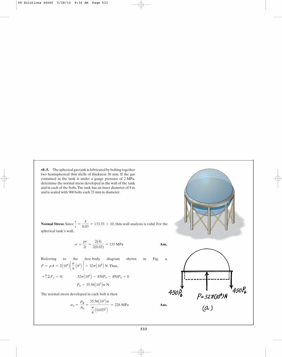
Normal Stress: Since , thin-wall analysis is valid. For the
spherical tank’s wall,
Ans.
Referring to the free-body diagram shown in Fig. a,
. Thus,
The normal stress developed in each bolt is then
Ans.sb =Pb
Ab=
35.56 A103 Bpp
4 A0.0252 B = 228 MPa
Pb = 35.56 A103 Bp N
+ c ©Fy = 0; 32p A106 B - 450Pb - 450Pb = 0
P = pA = 2 A106 B cp4
A82 B d = 32p A106 B Ns =
pr
2t=
2(4)2(0.03)
= 133 MPa
rt
= 40.03
= 133.33 7 10
•8–5. The spherical gas tank is fabricated by bolting togethertwo hemispherical thin shells of thickness 30 mm. If the gascontained in the tank is under a gauge pressure of 2 MPa,determine the normal stress developed in the wall of the tankand in each of the bolts.The tank has an inner diameter of 8 mand is sealed with 900 bolts each 25 mm in diameter.
Hoop Stress for Cylindrical Vessels: Since , then thin wall
analysis can be used. Applying Eq. 8–1
Ans.
Longitudinal Stress for Cylindrical Vessels: Applying Eq. 8–2
Ans.s2 =pr
2t=
90(11)2(0.25)
= 1980 psi = 1.98 ksi
s1 =pr
t=
90(11)0.25
= 3960 psi = 3.96 ksi
rt
= 110.25
= 44 7 10
*8–4. The tank of the air compressor is subjected to aninternal pressure of 90 psi. If the internal diameter ofthe tank is 22 in., and the wall thickness is 0.25 in.,determine the stress components acting at point A. Draw avolume element of the material at this point, and show theresults on the element. A
08 Solutions 46060 5/28/10 8:34 AM Page 533
537
© 2010 Pearson Education, Inc., Upper Saddle River, NJ. All rights reserved. This material is protected under all copyright laws as they currentlyexist. No portion of this material may be reproduced, in any form or by any means, without permission in writing from the publisher.
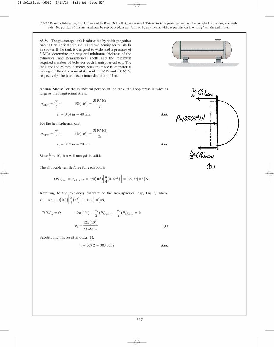
Normal Stress: For the cylindrical portion of the tank, the hoop stress is twice aslarge as the longitudinal stress.
Ans.
For the hemispherical cap,
Ans.
Since , thin-wall analysis is valid.
The allowable tensile force for each bolt is
Referring to the free-body diagram of the hemispherical cap, Fig. b, where
,
(1)
Substituting this result into Eq. (1),
Ans.ns = 307.2 = 308 bolts
ns =12p A106 B(Pb)allow
:+ ©Fx = 0; 12p A106 B -ns
2 (Pb)allow -
ns
2 (Pb)allow = 0
P = pA = 3 A106 B cp4
A42 B d = 12p A106 B N(Pb)allow = sallowAb = 250 A106 B cp
4A0.0252 B d = 122.72 A103 B N
rt
6 10
ts = 0.02 m = 20 mm
sallow =pr
t ; 150 A106 B =
3 A106 B(2)
2ts
tc = 0.04 m = 40 mm
sallow =pr
t ; 150 A106 B =
3 A106 B(2)
tc
•8–9. The gas storage tank is fabricated by bolting togethertwo half cylindrical thin shells and two hemispherical shellsas shown. If the tank is designed to withstand a pressure of3 MPa, determine the required minimum thickness of thecylindrical and hemispherical shells and the minimumrequired number of bolts for each hemispherical cap. Thetank and the 25 mm diameter bolts are made from materialhaving an allowable normal stress of 150 MPa and 250 MPa,respectively. The tank has an inner diameter of 4 m.
08 Solutions 46060 5/28/10 8:34 AM Page 537
581
© 2010 Pearson Education, Inc., Upper Saddle River, NJ. All rights reserved. This material is protected under all copyright laws as they currentlyexist. No portion of this material may be reproduced, in any form or by any means, without permission in writing from the publisher.
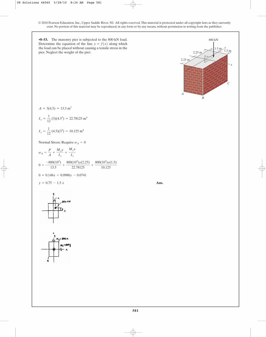
Normal Stress: Require
Ans.y = 0.75 - 1.5 x
0 = 0.148x + 0.0988y - 0.0741
0 =-800(103)
13.5+
800(103)y(2.25)22.78125
+800(103)x(1.5)
10.125
sA = PA
+Mxy
Ix+
Myx
Iy
sA = 0
Iy = 112
(4.5)(33) = 10.125 m4
Ix = 112
(3)(4.53) = 22.78125 m4
A = 3(4.5) = 13.5 m2
•8–53. The masonry pier is subjected to the 800-kN load.Determine the equation of the line along whichthe load can be placed without causing a tensile stress in thepier. Neglect the weight of the pier.
y = f1x22.25 m
2.25 m1.5 m
1.5 m
AB
C
y
xx
y
800 kN
08 Solutions 46060 5/28/10 8:34 AM Page 581
583
© 2010 Pearson Education, Inc., Upper Saddle River, NJ. All rights reserved. This material is protected under all copyright laws as they currentlyexist. No portion of this material may be reproduced, in any form or by any means, without permission in writing from the publisher.
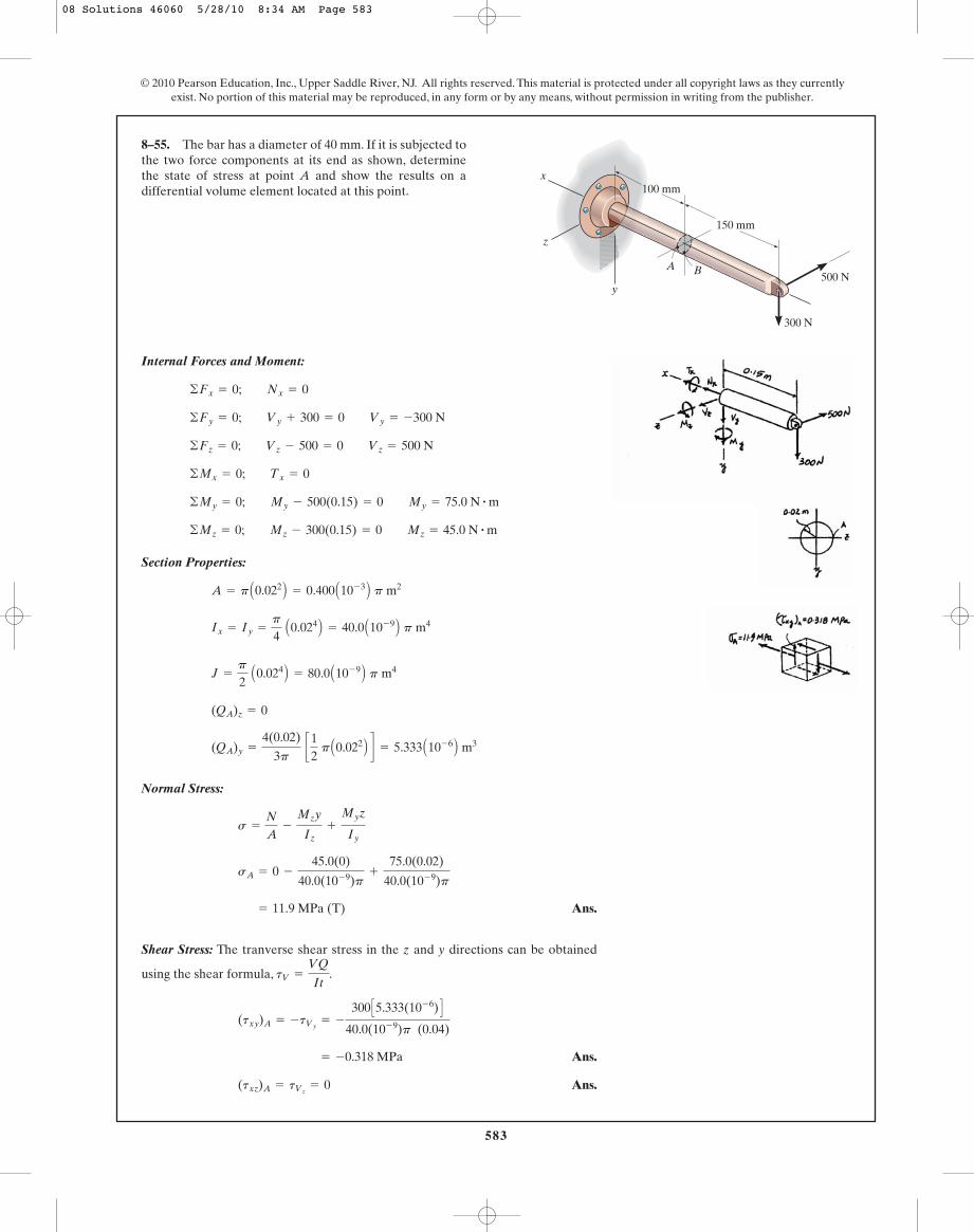
Internal Forces and Moment:
Section Properties:
Normal Stress:
Ans.
Shear Stress: The tranverse shear stress in the z and y directions can be obtained
using the shear formula, .
Ans.
Ans.(txz)A = tVz= 0
= -0.318 MPa
(txy)A = -tVy= -
300 C5.333(10- 6) D40.0(10- 9)p (0.04)
tV =VQ
It
= 11.9 MPa (T)
sA = 0 -45.0(0)
40.0(10- 9)p+
75.0(0.02)
40.0(10- 9)p
s = NA
-Mzy
Iz+
Myz
Iy
(QA)y =4(0.02)
3p c1
2 p A0.022 B d = 5.333 A10- 6 B m3
(QA)z = 0
J = p2
A0.024 B = 80.0 A10- 9 B p m4
Ix = Iy = p4
A0.024 B = 40.0 A10- 9 B p m4
A = p A0.022 B = 0.400 A10- 3 B p m2
©Mz = 0; Mz - 300(0.15) = 0 Mz = 45.0 N # m
©My = 0; My - 500(0.15) = 0 My = 75.0 N # m
©Mx = 0; Tx = 0
©Fz = 0; Vz - 500 = 0 Vz = 500 N
©Fy = 0; Vy + 300 = 0 Vy = -300 N
©Fx = 0; Nx = 0
8–55. The bar has a diameter of 40 mm. If it is subjected tothe two force components at its end as shown, determinethe state of stress at point A and show the results on adifferential volume element located at this point. 100 mm
150 mm
y
x
z
BA
300 N
500 N
08 Solutions 46060 5/28/10 8:34 AM Page 583
562
© 2010 Pearson Education, Inc., Upper Saddle River, NJ. All rights reserved. This material is protected under all copyright laws as they currentlyexist. No portion of this material may be reproduced, in any form or by any means, without permission in writing from the publisher.
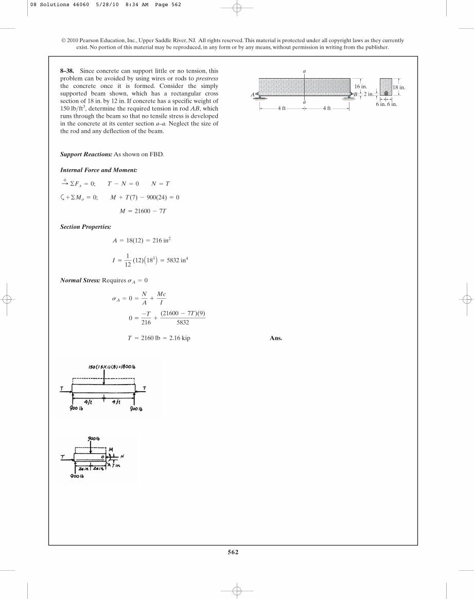
Support Reactions: As shown on FBD.
Internal Force and Moment:
a
Section Properties:
Normal Stress: Requires
Ans. T = 2160 lb = 2.16 kip
0 = -T216
+(21600 - 7T)(9)
5832
sA = 0 = NA
+ McI
sA = 0
I = 112
(12) A183 B = 5832 in4
A = 18(12) = 216 in2
M = 21600 - 7T
+ ©Mo = 0; M + T(7) - 900(24) = 0
:+ ©Fx = 0; T - N = 0 N = T
8–38. Since concrete can support little or no tension, thisproblem can be avoided by using wires or rods to prestressthe concrete once it is formed. Consider the simplysupported beam shown, which has a rectangular crosssection of 18 in. by 12 in. If concrete has a specific weight of
determine the required tension in rod AB, whichruns through the beam so that no tensile stress is developedin the concrete at its center section a–a. Neglect the size ofthe rod and any deflection of the beam.
150 lb>ft3,
16 in.
4 ft 4 fta
a
A B18 in.
6 in. 6 in.
2 in.
08 Solutions 46060 5/28/10 8:34 AM Page 562