Embed Size (px)
Citation preview
Addendum to Description of Services for Building and Planning, 2012
The Association of of Consulting Engineers
8.4 Digital Design
2016

FRI and DANSKE ARK
English translation of DoS Building and Planning, 2012, chapter 8.4 Digital Design final 14-04-2016 ver 1.01
Addendum to Description of Services for Building and Planning, 2012 - 8.4 Digital Design
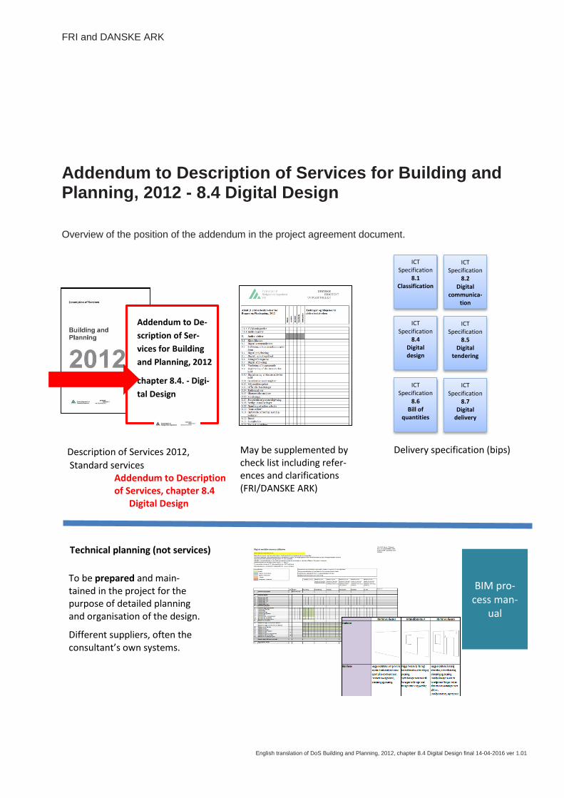
Overview of the position of the addendum in the project agreement document.
Addendum to De-
scription of Ser-
vices for Building
and Planning, 2012
chapter 8.4. - Digi-
tal Design
Delivery specification (bips) May be supplemented by check list including refer-ences and clarifications
(FRI/DANSKE ARK)
Technical planning (not services)
ICT Specification
8.1 Classification
To be prepared and main-tained in the project for the purpose of detailed planning and organisation of the design.
Different suppliers, often the consultant’s own systems.
BIM pro-cess man-
ual
Description of Services 2012,
Standard services Addendum to Description of Services, chapter 8.4 Digital Design
ICT Specification
8.2 Digital
communica-tion
ICT Specification
8.4 Digital design
ICT Specification
8.6 Bill of
quantities
ICT Specification
8.5 Digital
tendering
ICT Specification
8.7 Digital
delivery
8.4 Digital Design
2
This description of services for Digital Design is
an addendum to DANSKE ARK’s and FRI’s De-
scription of Services 2012 for Building and Plan-
ning, 2012 (DoS 2012).
The addendum combines chapter 3 “Design
phase consultancy” of the description of services
with chapter 8.4 “Digital Design” using building
models and, for building and discipline models,
states the extent of the digital project documenta-
tion for the individual phases. The left column of
the guideline includes the exact wording of chap-
ter 3 in the description of services. The right col-
umn describes the deliverables which are com-
mon with chapter 8.4. Digital Design.
The description of services describes only the
extent of the digital project documentation for pro-
ject implementation under DoS 2012.
Other chapter 8 services with ICT contents (Clas-
sification, Digital communication, Establishment of
communication platform, Digital tendering, tender-
ing, Bill of quantities and Digital delivery) are not
covered by the addendum to the description of
services.
The Description of Services for Digital Design is
used together with DoS 2012 in connection with
an agreement concluded between client and con-
sultant.
In the addendum, the term “Digital project docu-
mentation” means 3D building models used to
support the project drawing production for main
drawings and layout drawings and for area and
space extraction and as a basis for interdiscipli-
nary collision and consistency control in respect of
disciplines and phases.
All parties are responsible for their own building
models and for ensuring that these are well-
structured and mutually coordinated and that they
include objects with properties enabling sorting,
filtering and extraction in respect of the delivera-
bles of the phases.
In order to clarify and support the digital coopera-
tion between the project parties during the design
phase, a process description and a technical
specification must be prepared at project start-up,
describing the cooperation between disciplines
and phases with specification of processes and
building parts using, for example, objects, geome-
try and properties.
It is assumed that the project parties use their
own software. If the client wants other software,
this must be handled separately.
8.4 Digital Design Contents
3
3. Design phase consultancy
3.1 Outline proposal
3.2 Project proposal
3.3 Preliminary project (regulatory project)
3.4 Main project
3.5 Project follow-up
Glossary
3. Design phase consultancy 8.4 Digital Design
4
3. Design phase consultancy
3.1 OUTLINE PROPOSAL
DoS References
DoS 2012 Project documentation
8.4 Digital project documentation
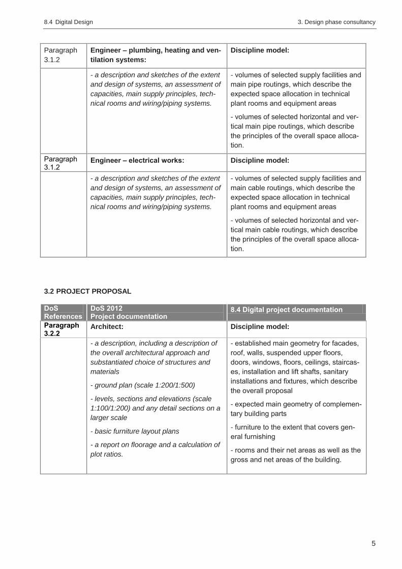
Paragraph
3.1.2
Architect: Discipline model:
- a description of the proposal, the archi-
tectural concept, functions and sustaina-
bility, including architectural reflections on
design and MEP principles
- proposals for the general choice of ma-
terials
- a site plan/layout plan showing the rela-
tive location of buildings (scale 1:500/
1:1000)
- plan and elevation drawings (scale
1:200/1:500)
- a report on floorage and plot ratios.
- selected facades, roofs, suspended
upper floors, columns and walls with
doors and windows, which describe the
main geometry and programmed princi-
ples of the overall proposal
- programmed rooms and their net areas
as well as the gross and net areas of the
building.
Paragraph
3.1.2
Landscape architect: Discipline model:
- a description of the proposal, including
preliminary studies and analyses under-
taken, a description of site area topogra-
phy, accessibility, climate, plants and
trees, soil and designation of utilisation of
open spaces, if any
- proposals for the general choice of ma-
terials and vegetation
- plan drawings (scale 1:500/1:1000) giv-
ing an overall impression of the site.
- selected terrain, paving and plants and
trees, which describe the overall planning
and principles of selected terrain adjust-
ment.
Paragraph
3.1.2
Engineer – structures: Discipline model:
- a description and sketches of design principles and main structural systems.
- selected wall structures, slab structures,
roof structures, columns and beams
which are important for the overall space
allocation, to the extent it is necessary to
supplement the contents of the architect
model.
8.4 Digital Design 3. Design phase consultancy
5
Paragraph
3.1.2
Engineer – plumbing, heating and ven-
tilation systems:
Discipline model:
- a description and sketches of the extent
and design of systems, an assessment of
capacities, main supply principles, tech-
nical rooms and wiring/piping systems.
- volumes of selected supply facilities and
main pipe routings, which describe the
expected space allocation in technical
plant rooms and equipment areas
- volumes of selected horizontal and ver-
tical main pipe routings, which describe
the principles of the overall space alloca-
tion.
Paragraph 3.1.2
Engineer – electrical works: Discipline model:
- a description and sketches of the extent
and design of systems, an assessment of
capacities, main supply principles, tech-
nical rooms and wiring/piping systems.
- volumes of selected supply facilities and
main cable routings, which describe the
expected space allocation in technical
plant rooms and equipment areas
- volumes of selected horizontal and ver-
tical main cable routings, which describe
the principles of the overall space alloca-
tion.
3.2 PROJECT PROPOSAL
DoS References
DoS 2012 Project documentation
8.4 Digital project documentation
Paragraph 3.2.2
Architect: Discipline model:
- a description, including a description of
the overall architectural approach and
substantiated choice of structures and
materials
- ground plan (scale 1:200/1:500)
- levels, sections and elevations (scale
1:100/1:200) and any detail sections on a
larger scale
- basic furniture layout plans
- a report on floorage and a calculation of
plot ratios.
- established main geometry for facades,
roof, walls, suspended upper floors,
doors, windows, floors, ceilings, staircas-
es, installation and lift shafts, sanitary
installations and fixtures, which describe
the overall proposal
- expected main geometry of complemen-
tary building parts
- furniture to the extent that covers gen-
eral furnishing
- rooms and their net areas as well as the
gross and net areas of the building.
3. Design phase consultancy 8.4 Digital Design
6
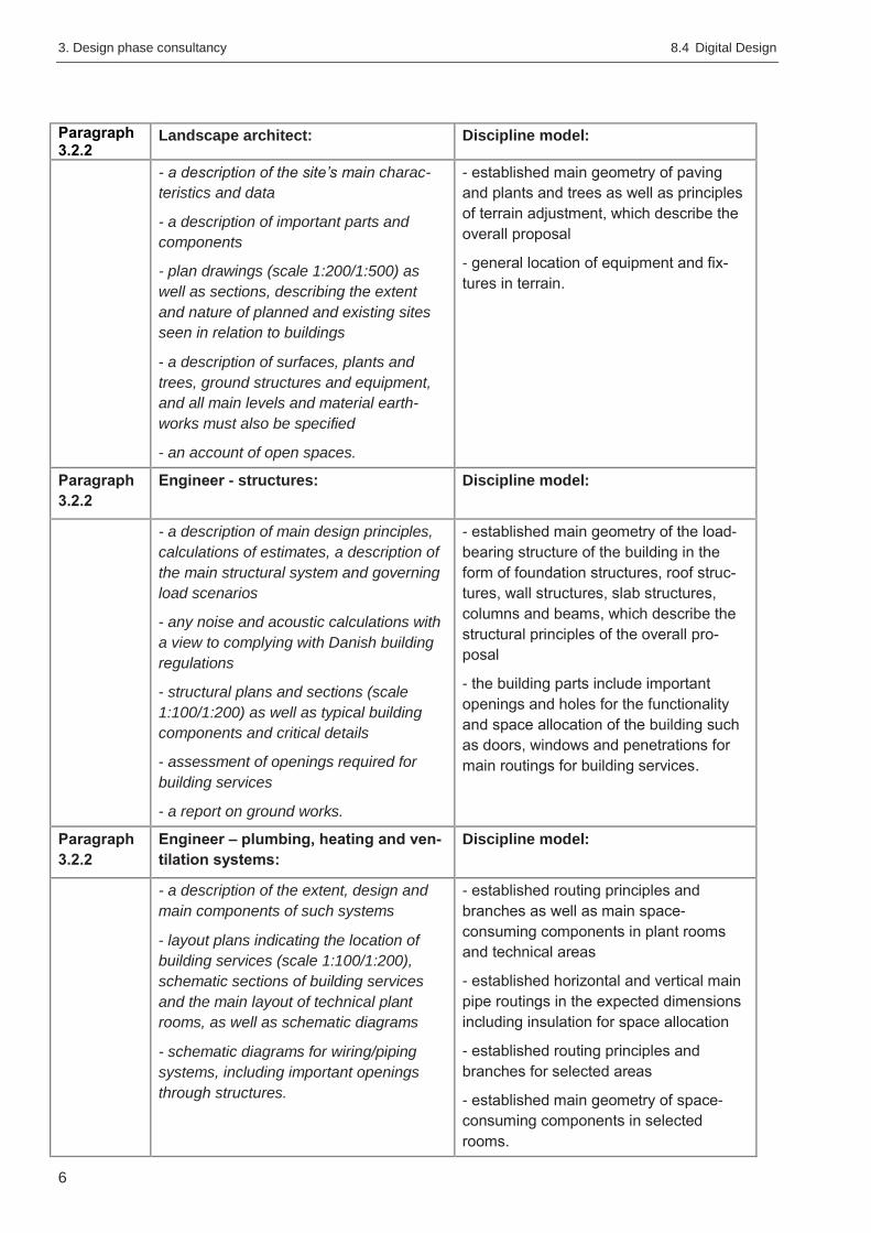
Paragraph 3.2.2
Landscape architect: Discipline model:
- a description of the site’s main charac-
teristics and data
- a description of important parts and
components
- plan drawings (scale 1:200/1:500) as
well as sections, describing the extent
and nature of planned and existing sites
seen in relation to buildings
- a description of surfaces, plants and
trees, ground structures and equipment,
and all main levels and material earth-
works must also be specified
- an account of open spaces.
- established main geometry of paving
and plants and trees as well as principles
of terrain adjustment, which describe the
overall proposal
- general location of equipment and fix-
tures in terrain.
Paragraph
3.2.2
Engineer - structures: Discipline model:
- a description of main design principles,
calculations of estimates, a description of
the main structural system and governing
load scenarios
- any noise and acoustic calculations with
a view to complying with Danish building
regulations
- structural plans and sections (scale
1:100/1:200) as well as typical building
components and critical details
- assessment of openings required for
building services
- a report on ground works.
- established main geometry of the load-
bearing structure of the building in the
form of foundation structures, roof struc-
tures, wall structures, slab structures,
columns and beams, which describe the
structural principles of the overall pro-
posal
- the building parts include important
openings and holes for the functionality
and space allocation of the building such
as doors, windows and penetrations for
main routings for building services.
Paragraph
3.2.2
Engineer – plumbing, heating and ven-
tilation systems:
Discipline model:
- a description of the extent, design and
main components of such systems
- layout plans indicating the location of
building services (scale 1:100/1:200),
schematic sections of building services
and the main layout of technical plant
rooms, as well as schematic diagrams
- schematic diagrams for wiring/piping
systems, including important openings
through structures.
- established routing principles and
branches as well as main space-
consuming components in plant rooms
and technical areas
- established horizontal and vertical main
pipe routings in the expected dimensions
including insulation for space allocation
- established routing principles and
branches for selected areas
- established main geometry of space-
consuming components in selected
rooms.
8.4 Digital Design 3. Design phase consultancy
7
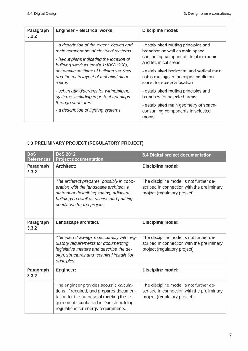
Paragraph
3.2.2
Engineer – electrical works: Discipline model:
- a description of the extent, design and
main components of electrical systems
- layout plans indicating the location of
building services (scale 1:100/1:200),
schematic sections of building services
and the main layout of technical plant
rooms
- schematic diagrams for wiring/piping
systems, including important openings
through structures
- a description of lighting systems.
- established routing principles and
branches as well as main space-
consuming components in plant rooms
and technical areas
- established horizontal and vertical main
cable routings in the expected dimen-
sions, for space allocation
- established routing principles and
branches for selected areas
- established main geometry of space-
consuming components in selected
rooms.
3.3 PRELIMINARY PROJECT (REGULATORY PROJECT)
DoS References
DoS 2012 Project documentation
8.4 Digital project documentation
Paragraph
3.3.2
Architect: Discipline model:
The architect prepares, possibly in coop-
eration with the landscape architect, a
statement describing zoning, adjacent
buildings as well as access and parking
conditions for the project.
The discipline model is not further de-
scribed in connection with the preliminary
project (regulatory project).
Paragraph
3.3.2
Landscape architect: Discipline model:
The main drawings must comply with reg-
ulatory requirements for documenting
legislative matters and describe the de-
sign, structures and technical installation
principles.
The discipline model is not further de-
scribed in connection with the preliminary
project (regulatory project).
Paragraph
3.3.2
Engineer: Discipline model:
The engineer provides acoustic calcula-
tions, if required, and prepares documen-
tation for the purpose of meeting the re-
quirements contained in Danish building
regulations for energy requirements.
The discipline model is not further de-
scribed in connection with the preliminary
project (regulatory project).
3. Design phase consultancy 8.4 Digital Design
8
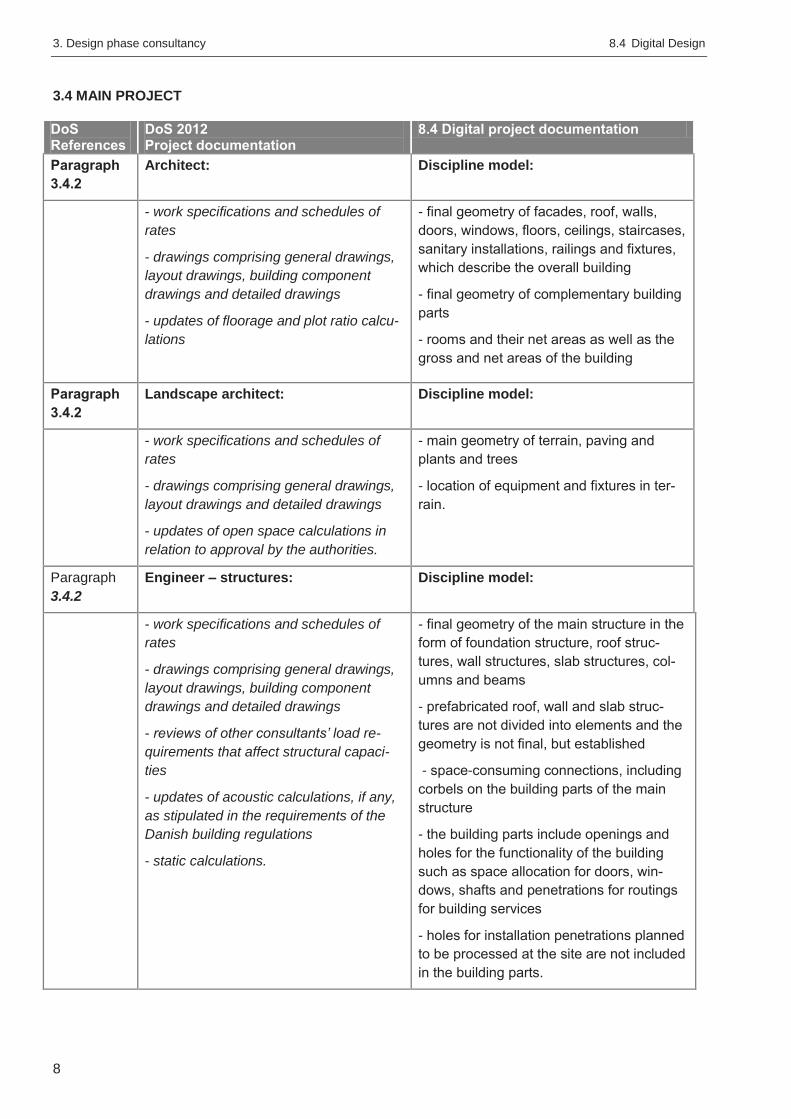
3.4 MAIN PROJECT
DoS References
DoS 2012 Project documentation
8.4 Digital project documentation
Paragraph
3.4.2
Architect: Discipline model:
- work specifications and schedules of
rates
- drawings comprising general drawings,
layout drawings, building component
drawings and detailed drawings
- updates of floorage and plot ratio calcu-
lations
- final geometry of facades, roof, walls,
doors, windows, floors, ceilings, staircases,
sanitary installations, railings and fixtures,
which describe the overall building
- final geometry of complementary building
parts
- rooms and their net areas as well as the
gross and net areas of the building
Paragraph
3.4.2
Landscape architect: Discipline model:
- work specifications and schedules of
rates
- drawings comprising general drawings,
layout drawings and detailed drawings
- updates of open space calculations in
relation to approval by the authorities.
- main geometry of terrain, paving and
plants and trees
- location of equipment and fixtures in ter-
rain.
Paragraph
3.4.2
Engineer – structures: Discipline model:
- work specifications and schedules of
rates
- drawings comprising general drawings,
layout drawings, building component
drawings and detailed drawings
- reviews of other consultants’ load re-
quirements that affect structural capaci-
ties
- updates of acoustic calculations, if any,
as stipulated in the requirements of the
Danish building regulations
- static calculations.
- final geometry of the main structure in the
form of foundation structure, roof struc-
tures, wall structures, slab structures, col-
umns and beams
- prefabricated roof, wall and slab struc-
tures are not divided into elements and the
geometry is not final, but established
- space-consuming connections, including
corbels on the building parts of the main
structure
- the building parts include openings and
holes for the functionality of the building
such as space allocation for doors, win-
dows, shafts and penetrations for routings
for building services
- holes for installation penetrations planned
to be processed at the site are not included
in the building parts.
8.4 Digital Design 3. Design phase consultancy
9
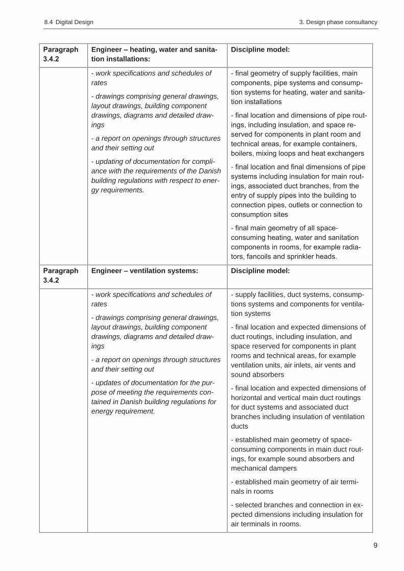
Paragraph
3.4.2
Engineer – heating, water and sanita-
tion installations:
Discipline model:
- work specifications and schedules of
rates
- drawings comprising general drawings,
layout drawings, building component
drawings, diagrams and detailed draw-
ings
- a report on openings through structures
and their setting out
- updating of documentation for compli-
ance with the requirements of the Danish
building regulations with respect to ener-
gy requirements.
- final geometry of supply facilities, main
components, pipe systems and consump-
tion systems for heating, water and sanita-
tion installations
- final location and dimensions of pipe rout-
ings, including insulation, and space re-
served for components in plant room and
technical areas, for example containers,
boilers, mixing loops and heat exchangers
- final location and final dimensions of pipe
systems including insulation for main rout-
ings, associated duct branches, from the
entry of supply pipes into the building to
connection pipes, outlets or connection to
consumption sites
- final main geometry of all space-
consuming heating, water and sanitation
components in rooms, for example radia-
tors, fancoils and sprinkler heads.
Paragraph
3.4.2
Engineer – ventilation systems: Discipline model:
- work specifications and schedules of
rates
- drawings comprising general drawings,
layout drawings, building component
drawings, diagrams and detailed draw-
ings
- a report on openings through structures
and their setting out
- updates of documentation for the pur-
pose of meeting the requirements con-
tained in Danish building regulations for
energy requirement.
- supply facilities, duct systems, consump-
tions systems and components for ventila-
tion systems
- final location and expected dimensions of
duct routings, including insulation, and
space reserved for components in plant
rooms and technical areas, for example
ventilation units, air inlets, air vents and
sound absorbers
- final location and expected dimensions of
horizontal and vertical main duct routings
for duct systems and associated duct
branches including insulation of ventilation
ducts
- established main geometry of space-
consuming components in main duct rout-
ings, for example sound absorbers and
mechanical dampers
- established main geometry of air termi-
nals in rooms
- selected branches and connection in ex-
pected dimensions including insulation for
air terminals in rooms.
3. Design phase consultancy 8.4 Digital Design
10
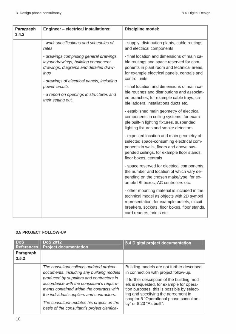
Paragraph
3.4.2
Engineer – electrical installations: Discipline model:
- work specifications and schedules of
rates
- drawings comprising general drawings,
layout drawings, building component
drawings, diagrams and detailed draw-
ings
- drawings of electrical panels, including
power circuits
- a report on openings in structures and
their setting out.
- supply, distribution plants, cable routings
and electrical components
- final location and dimensions of main ca-
ble routings and space reserved for com-
ponents in plant room and technical areas,
for example electrical panels, centrals and
control units
- final location and dimensions of main ca-
ble routings and distributions and associat-
ed branches, for example cable trays, ca-
ble ladders, installations ducts etc.
- established main geometry of electrical
components in ceiling systems, for exam-
ple built-in lighting fixtures, suspended
lighting fixtures and smoke detectors
- expected location and main geometry of
selected space-consuming electrical com-
ponents in walls, floors and above sus-
pended ceilings, for example floor stands,
floor boxes, centrals
- space reserved for electrical components,
the number and location of which vary de-
pending on the chosen make/type, for ex-
ample IBI boxes, AC controllers etc.
- other mounting material is included in the
technical model as objects with 2D symbol
representation, for example outlets, circuit
breakers, sockets, floor boxes, floor stands,
card readers, prints etc.
3.5 PROJECT FOLLOW-UP
DoS References
DoS 2012 Project documentation
8.4 Digital project documentation
Paragraph
3.5.2
The consultant collects updated project
documents, including any building models
produced by suppliers and contractors in
accordance with the consultant's require-
ments contained within the contracts with
the individual suppliers and contractors.
The consultant updates his project on the
basis of the consultant’s project clarifica-
Building models are not further described
in connection with project follow-up.
If further description of the building mod-els is requested, for example for opera-tion purposes, this is possible by select-ing and specifying the agreement in chapter 5 “Operational phase consultan-cy” or 8.20 “As built”.
8.4 Digital Design 3. Design phase consultancy
11
tions and any additional design performed
by the consultant. The update is per-
formed to an extent that permits regulato-
ry approval and an occupancy permit
within the consultant's area of responsibil-
ity.
In digital design, the scope of the building
models must be determined in an ICT
specification, such that coordinated build-
ing models and project documentation
can be supplied in digital form.
Building models may be utilised to pro-
duce visualisations for suppliers and con-
tractors during the building project, corre-
sponding to the project phase.
Glossary 8.4 Digital Design
12
Glossary
In general, the definitions from DoS Building
and Planning 2012
Principle
Illustrates a basic idea which, in the consultant’s
assessment, can be implemented in the building
project after further detailing.
Expected main geometry/geometry
Indicates that the geometrical shape of the ob-
ject/building element has not been defined and
that the location in the building has not been de-
termined.
Established main geometry/geometry
Indicates that the geometrical shape and location
of the object/structural member in the building
have been clarified and established, but adjust-
ment may be made before the final shape and
location are defined and decided.
Final main geometry/geometry
Indicates that the object/structural member has
been finally clarified with respect to shape and
location.
Selected
The consultant selects important elements/parts,
which are detailed in the model. The selected
parts illustrate typical parts (repeated many times)
or critical parts (difficult with respect to technical
solution or buildability).
Delivery
Indicates output. Delivery does not include a de-
scription of the process. A delivery usually re-
quires the delivery of a service.
Discipline model
A building model which includes information relat-
ed to a specific discipline / area of responsibility,
for example architecture, structures, building in-
stallations.
Building model
A building illustrated in a digital model. A building
model may include the entire building or parts of
the entire building and may be represented by
geometrical as well as non-geometrical infor-
mation.