Embed Size (px)
Citation preview
Microprocessor & Interfacing Lecture 28
8259 Programmable Interrupt Controller-- 1
E C S D E P A R T M E N T
D R O N A C H A R Y A C O L L E G E O F E N G I N E E R I N G
Contents
Introduction
Processing Interrupts
8086/88 Hardware Interrupt Pins
Interrupt Flag
8259
Pin Description
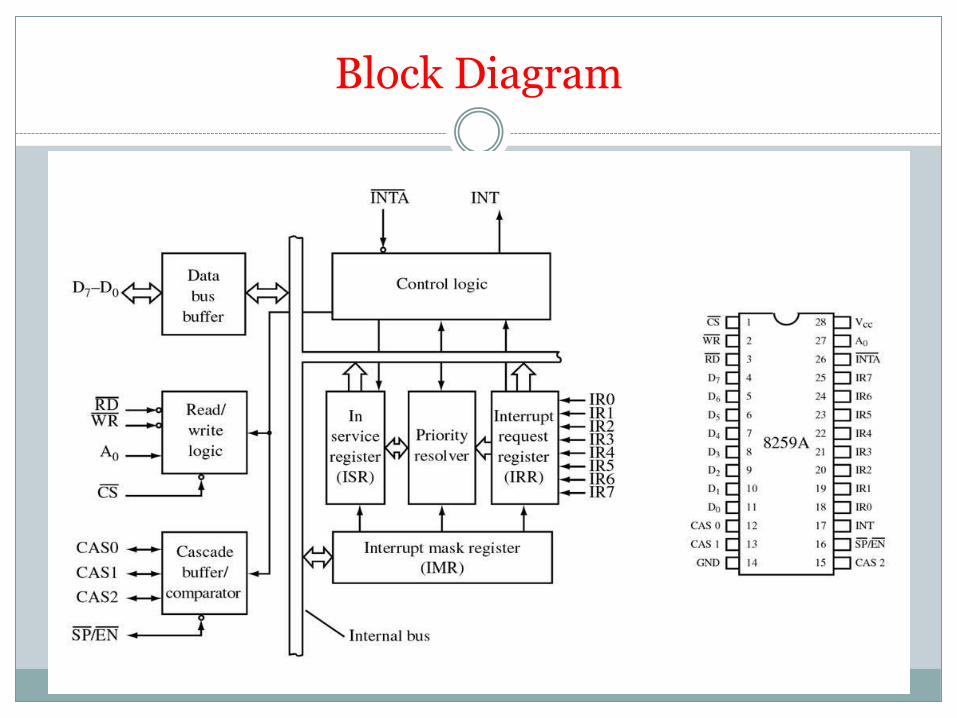
Block Diagram
Interfacing
Operation
Introduction
An interrupt is an event which informs the
CPU that its service (action) is needed.
Sources of interrupts:
internal fault (e.g.. divide by zero, overflow)
Software
external hardware : maskable, nonmaskable
reset
Processing Interrupts
When an interrupt is executed, the microprocessor:
finishes executing its current instruction (if any).
saves (PUSH) the flag register, IP and CS register in the stack.
goes to a fixed memory location.
reads the address of the associated ISR.
Jumps to that address and executes the ISR.
gets (PULL) the flag register, CS:IP register from the stack.
continues executing the previous job (if any).
8086/88 Hardware Interrupt Pins
INTR: Interrupt Request. Input signal into the CPU
If it is activated, the CPU will finish the current instruction and respond with the interrupt acknowledge operation
Can be masked (ignored) thru instructions CLI and STI
NMI: NonMaskable interrupt. Input signal
Cannot be masked or unmasked thru CLI and STI
Examples of use: power frailer. Memory error
INTA: Interrupt Acknowledge. Output signal
Interrupt Flag
IF (Interrupt Enable Flag) D9: used to mask any hardware
interrupt that may come in from the INTR pin.
When IF=0, all hardware interrupt requests through INTR
are masked.
This has no effect on interrupts coming from the NMI pin
or “INT nn” instructions.
CLI sets IF to 0, STI sets IF to 1.
INT n and ISR
n is multiplied by 4
In the address “4n” the offset address the ISR is found.
Example:Intel has set aside INT 2 for the NMI interrupt.
Whenever the NMI pin is activated, the CPU jumps to
physical memory location 00008 to fetch the CS:IP of the
interrupt service routine associated with the NMI.

8259
8259 is Programmable Interrupt Controller (PIC)
It is a tool for managing the interrupt requests.
8259 is a very flexible peripheral controller chip: PIC can deal with up to 64 interrupt inputs
interrupts can be masked
various priority schemes can also programmed.
Originally (in PC XT) it is available as a separate IC
Later the functionality of (two PICs) is in the motherboards chipset.
In some of the modern processors, the functionality of the PIC is built in.
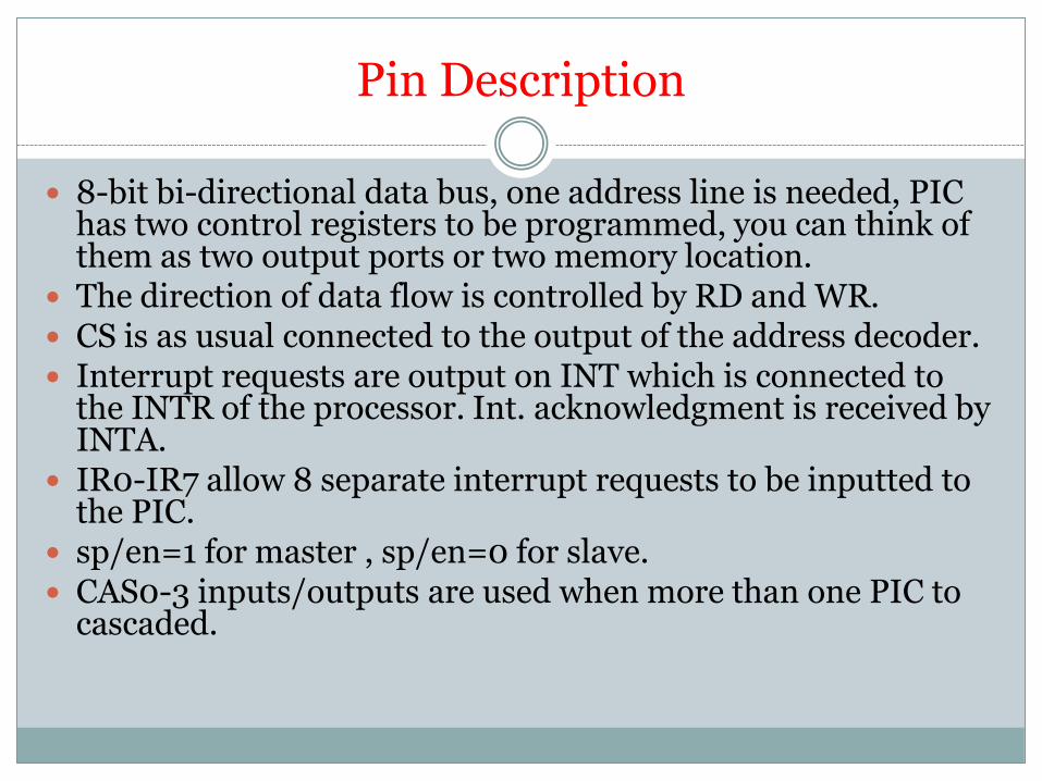
Pin Description
8-bit bi-directional data bus, one address line is needed, PIC has two control registers to be programmed, you can think of them as two output ports or two memory location.
The direction of data flow is controlled by RD and WR. CS is as usual connected to the output of the address decoder. Interrupt requests are output on INT which is connected to
the INTR of the processor. Int. acknowledgment is received by INTA.
IR0-IR7 allow 8 separate interrupt requests to be inputted to the PIC.
sp/en=1 for master , sp/en=0 for slave. CAS0-3 inputs/outputs are used when more than one PIC to
cascaded.
Block Diagram
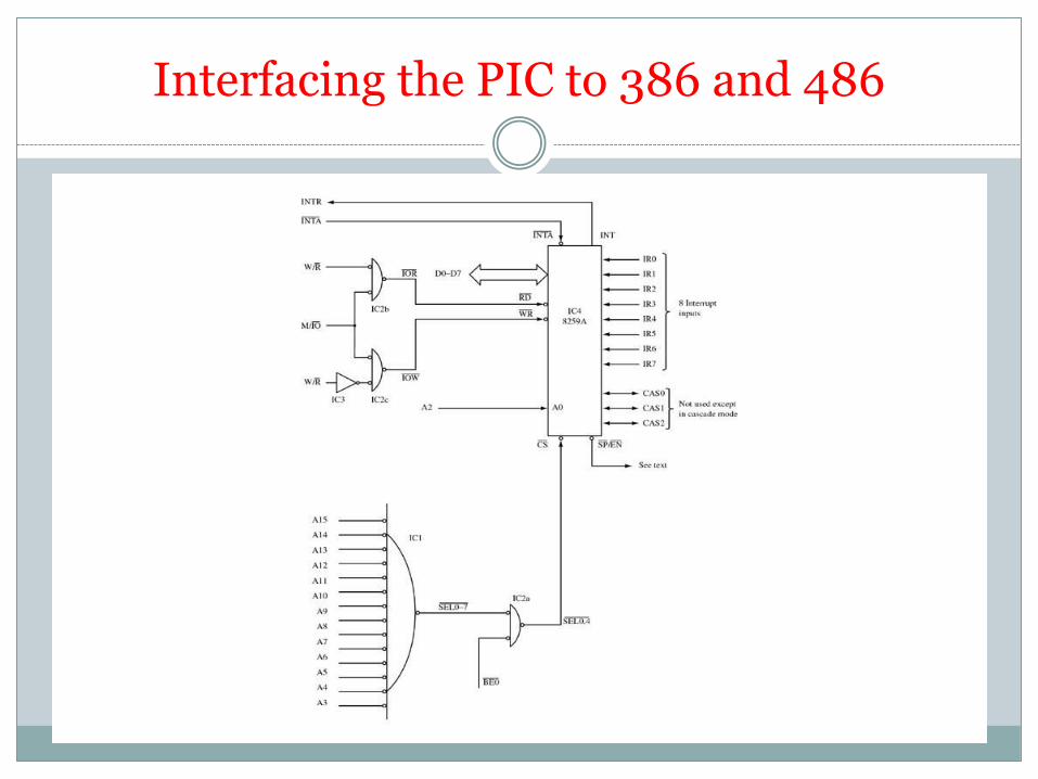
Interfacing the PIC to 386 and 486
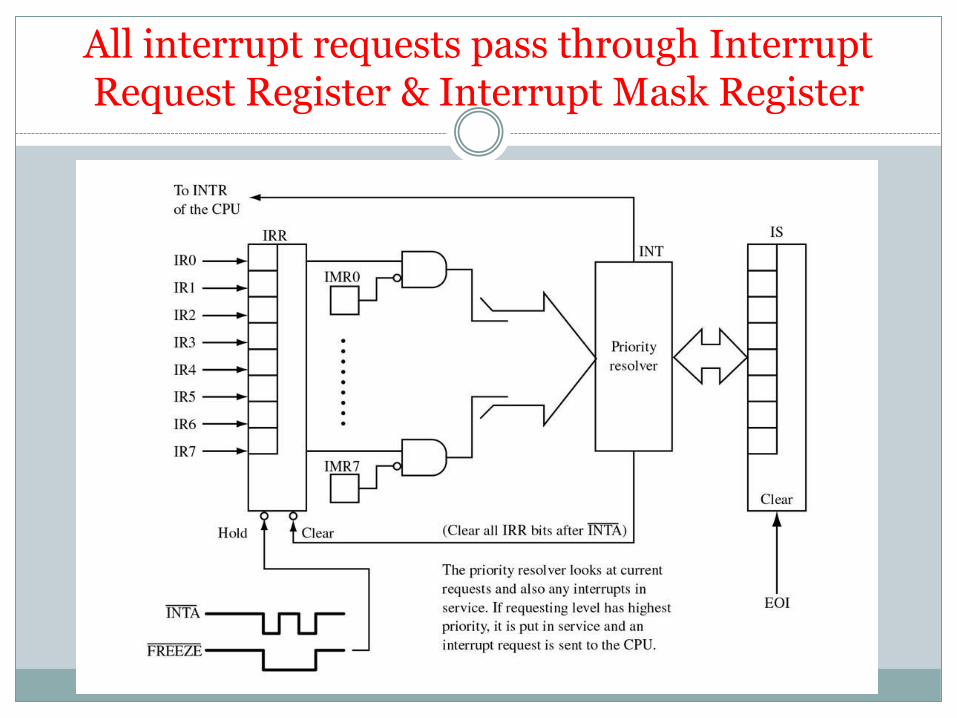
All interrupt requests pass through Interrupt Request Register & Interrupt Mask Register
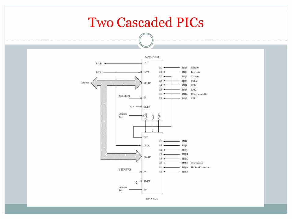
Two Cascaded PICs
Operation
PIC is to be initialized and programmed to control its
operation.
The operation in simple words:
When an interrupt occurs , the PIC determines the highest priority,
activates the processor via its INTR input, and sends the type number
onto the data bus when the processor acknowledges the interrupt.
Priority:
What is used in PC is fully nested mode. That is the lowest numbered
IRQ input has highest priority. Lower priority interrupts will not be
forwarded to the processor until the higher priority interrupts have
been serviced.