Embed Size (px)
Citation preview

SA4550 Primary Attitude Display
Installation Manual Revision G
Sandel Avionics, Inc. 2401 Dogwood Way
Vista, CA 92081 Phone (760) 727- 4900
FAX 760) 727- 4899
Website: www.sandel.com Email: [email protected]

82010-IM, REV. G Sandel SA4550 Installation Manual Page ii
[This page intentionally left blank]
82010-IM, REV. G Sandel SA4550 Installation Manual Page iii
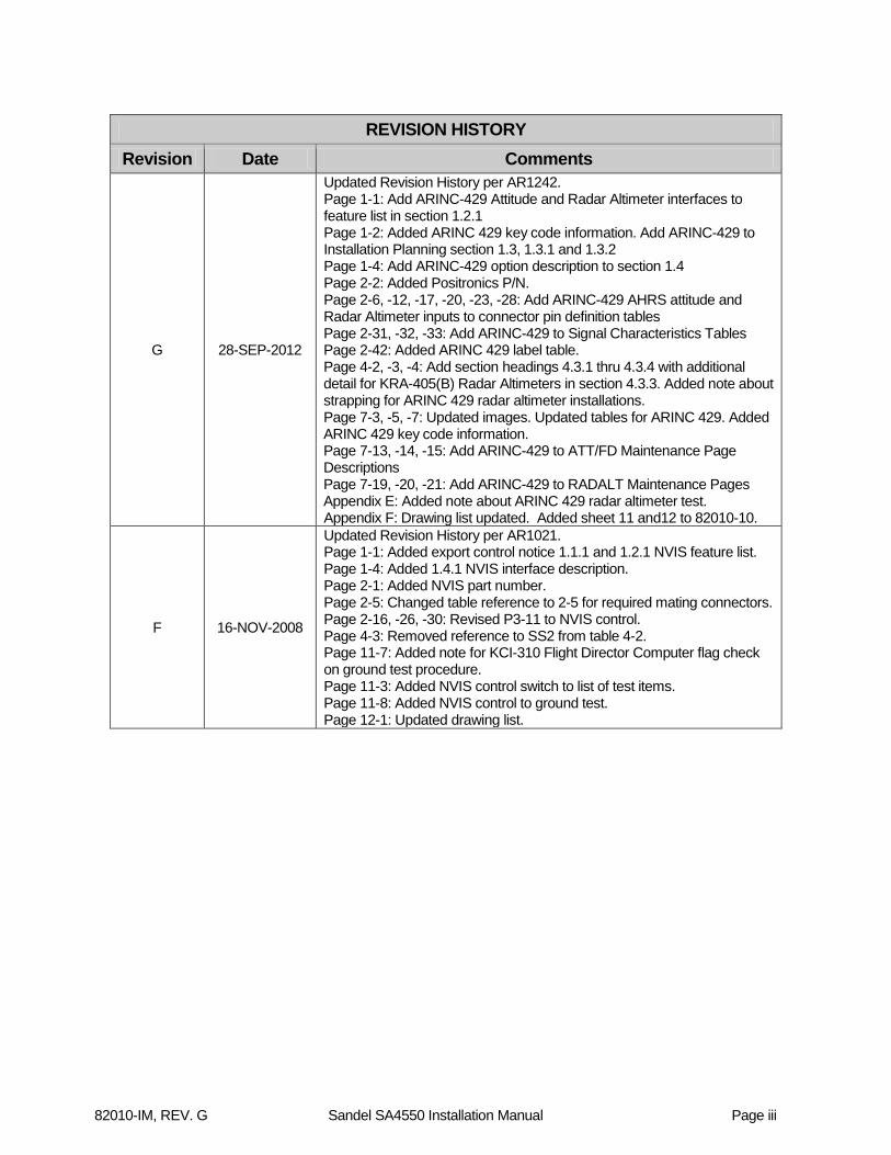
REVISION HISTORY
Revision Date Comments
G 28-SEP-2012
Updated Revision History per AR1242. Page 1-1: Add ARINC-429 Attitude and Radar Altimeter interfaces to feature list in section 1.2.1 Page 1-2: Added ARINC 429 key code information. Add ARINC-429 to Installation Planning section 1.3, 1.3.1 and 1.3.2 Page 1-4: Add ARINC-429 option description to section 1.4 Page 2-2: Added Positronics P/N. Page 2-6, -12, -17, -20, -23, -28: Add ARINC-429 AHRS attitude and Radar Altimeter inputs to connector pin definition tables Page 2-31, -32, -33: Add ARINC-429 to Signal Characteristics Tables Page 2-42: Added ARINC 429 label table. Page 4-2, -3, -4: Add section headings 4.3.1 thru 4.3.4 with additional detail for KRA-405(B) Radar Altimeters in section 4.3.3. Added note about strapping for ARINC 429 radar altimeter installations. Page 7-3, -5, -7: Updated images. Updated tables for ARINC 429. Added ARINC 429 key code information. Page 7-13, -14, -15: Add ARINC-429 to ATT/FD Maintenance Page Descriptions Page 7-19, -20, -21: Add ARINC-429 to RADALT Maintenance Pages Appendix E: Added note about ARINC 429 radar altimeter test. Appendix F: Drawing list updated. Added sheet 11 and12 to 82010-10.
F 16-NOV-2008
Updated Revision History per AR1021. Page 1-1: Added export control notice 1.1.1 and 1.2.1 NVIS feature list. Page 1-4: Added 1.4.1 NVIS interface description. Page 2-1: Added NVIS part number. Page 2-5: Changed table reference to 2-5 for required mating connectors. Page 2-16, -26, -30: Revised P3-11 to NVIS control. Page 4-3: Removed reference to SS2 from table 4-2. Page 11-7: Added note for KCI-310 Flight Director Computer flag check on ground test procedure. Page 11-3: Added NVIS control switch to list of test items. Page 11-8: Added NVIS control to ground test. Page 12-1: Updated drawing list.

82010-IM, REV. G Sandel SA4550 Installation Manual Page iv
REVISION HISTORY Revision Date Comments
E 15-JUL-2008
Installation Manual updated to add support for Bendix/King models. Page 1-1: Added KCI-310 to introduction Page 1-3: Added King models to Table 1-3 Page 2-1: Added KCI-310 to P/N descriptions Page 2-2: Added USB cable to Bill of Materials Page 2-4: Added KCI-310 to Physical Dimensions description Page 2-5: Added KCI-310 to Table 2-5 Page 2-27: Added pages 2-27 through 2-29 to Connector Summary for KCI-310 models Page2-30: Added power connector P-3 pin definitions. Page 2-33: Added page for Bendix/King models. Page 2-41: Added page for signal scaling and thresholds for Bendix/King models Page 4-1: Note added for radar altimeters Page 4-2: Notes added for radar altimeters. Page 4-2: Corrected RADALT strapping for SA4550 Collins Page 4-2 : Added Table 4-1C for KCI310/310A models. Bendix/King KRA-405/405B radar altimeter compatibility notes added. Updated maintenance page descriptions added: Page 7-5: Maintenance Page 2: added page for Bendix/King models Page 7-7: Maintenance Page 3: added page for Bendix/King models Page 7-10: Maintenance Page 4: added page for Bendix/King models Page 7-13: Maintenance Page 5: added page for Bendix/King models Page 7-16: Maintenance Page 6: added page for Bendix/King models Page 7-19: Maintenance Page 7: added page for Bendix/King models Page 7-22: Maintenance Page 8: added page for Bendix/King models Appendix E, page 11-4: added note about ARINC 429 radar altimeter test. Appendix F: Drawing List updated
D 3-MAR-2008
Installation Manual updated to add support for Collins models Page 1-3: Added Collins Models to Table 1-3 Sections 2 thru 4: Updated for Collins replacement models. Updated maintenance page descriptions added: Page 7-4: Maintenance Page 2: added page for Collins models Page 7-7: Maintenance Page 4: added page for Collins models Page 7-9: Maintenance Page 5: added page for Collins models Page 7-11: Maintenance Page 6: added page for Collins models Page 7-13: Maintenance Page 7: added page for Collins models Page 7-15: Maintenance Page 8: added page for Collins models Added drawing 82010-10 sheet 7
C 12-OCT-2007
Clarified signal types. Added compatible Sperry Model/Part Numbers Added drawings 82010-IM Sheets 5 and 6 Modified drawings 82010-IM sheets 1 and 2. Modified ground test procedure to use maintenance page for RADAR Alt check. Updated Appendix F
B1 30-AUG-2007
Following three pages updated for Revision B1: Page iii, Revision History updated with B1 changes Page 1-4, Table 4-1 Pin labels for SA-4550-1xx corrected Drawing 82010-10 sheet 4, Pin strapping corrected for Collins Alt-50 and ARINC 552.
B 18-JUNE-2007 Additional Maintenance Page descriptions added.

82010-IM, REV. G Sandel SA4550 Installation Manual Page v
REVISION HISTORY Revision Date Comments
A 04-MAY-2007 Initial release
82010-IM, REV. G Sandel SA4550 Installation Manual Page vi
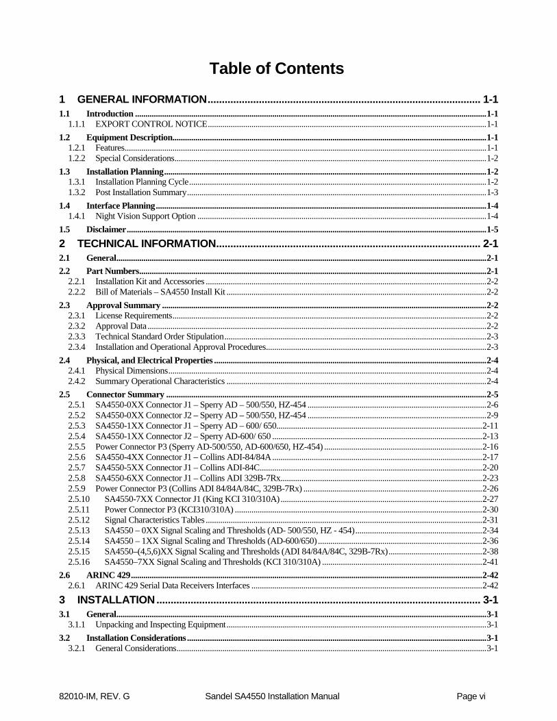
Table of Contents
1 GENERAL INFORMATION ................................................................................................ 1-1 1.1 Introduction ......................................................................................................................................................................... 1-1
1.1.1 EXPORT CONTROL NOTICE ...................................................................................................................................... 1-1 1.2 Equipment Description....................................................................................................................................................... 1-1
1.2.1 Features .............................................................................................................................................................................. 1-1 1.2.2 Special Considerations ...................................................................................................................................................... 1-2
1.3 Installation Planning ........................................................................................................................................................... 1-2 1.3.1 Installation Planning Cycle ............................................................................................................................................... 1-2 1.3.2 Post Installation Summary ................................................................................................................................................ 1-3
1.4 Interface Planning ............................................................................................................................................................... 1-4 1.4.1 Night Vision Support Option ........................................................................................................................................... 1-4
1.5 Disclaimer ............................................................................................................................................................................. 1-5 2 TECHNICAL INFORMATION ............................................................................................. 2-1 2.1 General .................................................................................................................................................................................. 2-1 2.2 Part Numbers ....................................................................................................................................................................... 2-1
2.2.1 Installation Kit and Accessories ....................................................................................................................................... 2-2 2.2.2 Bill of Materials – SA4550 Install Kit ............................................................................................................................. 2-2
2.3 Approval Summary ............................................................................................................................................................ 2-2 2.3.1 License Requirements ....................................................................................................................................................... 2-2 2.3.2 Approval Data ................................................................................................................................................................... 2-2 2.3.3 Technical Standard Order Stipulation .............................................................................................................................. 2-3 2.3.4 Installation and Operational Approval Procedures .......................................................................................................... 2-3
2.4 Physical, and Electrical Properties ................................................................................................................................... 2-4 2.4.1 Physical Dimensions ......................................................................................................................................................... 2-4 2.4.2 Summary Operational Characteristics ............................................................................................................................. 2-4
2.5 Connector Summary .......................................................................................................................................................... 2-5 2.5.1 SA4550-0XX Connector J1 – Sperry AD – 500/550, HZ-454 ...................................................................................... 2-6 2.5.2 SA4550-0XX Connector J2 – Sperry AD – 500/550, HZ-454 ...................................................................................... 2-9 2.5.3 SA4550-1XX Connector J1 – Sperry AD – 600/ 650................................................................................................... 2-11 2.5.4 SA4550-1XX Connector J2 – Sperry AD-600/ 650 ..................................................................................................... 2-13 2.5.5 Power Connector P3 (Sperry AD-500/550, AD-600/650, HZ-454) ............................................................................ 2-16 2.5.6 SA4550-4XX Connector J1 – Collins ADI-84/84A ..................................................................................................... 2-17 2.5.7 SA4550-5XX Connector J1 – Collins ADI-84C ........................................................................................................... 2-20 2.5.8 SA4550-6XX Connector J1 – Collins ADI 329B-7Rx................................................................................................. 2-23 2.5.9 Power Connector P3 (Collins ADI 84/84A/84C, 329B-7Rx) ...................................................................................... 2-26 2.5.10 SA4550-7XX Connector J1 (King KCI 310/310A) ................................................................................................. 2-27 2.5.11 Power Connector P3 (KCI310/310A) ....................................................................................................................... 2-30 2.5.12 Signal Characteristics Tables ..................................................................................................................................... 2-31 2.5.13 SA4550 – 0XX Signal Scaling and Thresholds (AD- 500/550, HZ - 454) ............................................................. 2-34 2.5.14 SA4550 – 1XX Signal Scaling and Thresholds (AD-600/650) ............................................................................... 2-36 2.5.15 SA4550–(4,5,6)XX Signal Scaling and Thresholds (ADI 84/84A/84C, 329B-7Rx) ............................................. 2-38 2.5.16 SA4550–7XX Signal Scaling and Thresholds (KCI 310/310A) ............................................................................. 2-41
2.6 ARINC 429 ......................................................................................................................................................................... 2-42 2.6.1 ARINC 429 Serial Data Receivers Interfaces ............................................................................................................... 2-42
3 INSTALLATION .................................................................................................................. 3-1 3.1 General .................................................................................................................................................................................. 3-1
3.1.1 Unpacking and Inspecting Equipment ............................................................................................................................. 3-1 3.2 Installation Considerations ................................................................................................................................................ 3-1
3.2.1 General Considerations ..................................................................................................................................................... 3-1

82010-IM, REV. G Sandel SA4550 Installation Manual Page vii
3.2.2 Cooling Considerations .................................................................................................................................................... 3-1 3.2.3 Mechanical Installation Considerations ........................................................................................................................... 3-1 3.2.4 Electrical Installation Considerations ............................................................................................................................... 3-2
4 SETUP PROCEDURES ...................................................................................................... 4-1 4.1 General .................................................................................................................................................................................. 4-1 4.2 Accessing the Maintenance Menus ................................................................................................................................... 4-1 4.3 Equipment/Configuration Selections ............................................................................................................................... 4-2
4.3.1 Radar Altimeter Configuration for Sperry Indicators ..................................................................................................... 4-2 4.3.2 Radar Altimeter Configuration for Collins Indicators ..................................................................................................... 4-2 4.3.3 Radar Altimeter Configuration for King KCI-310/310A Indicators .............................................................................. 4-2 4.3.4 Sperry Indicators P3 Pin Configuration Strapping .......................................................................................................... 4-3
5 OPERATING DETAILS ...................................................................................................... 5-1 6 INSTRUCTIONS FOR CONTINUED AIRWORTHINESS ................................................. 6-1 7 APPENDIX A: POST-INSTALLATION PROCEDURES.................................................. 7-1 7.1 Page 1: INDEX – All Models ............................................................................................................................................ 7-2 7.2 Page 2: INSTALLATION – Sperry Models .................................................................................................................. 7-3 7.3 Page 2: INSTALLATION – Collins Models .................................................................................................................. 7-5 7.4 Page 2: INSTALLATION – Bendix/King Models ........................................................................................................ 7-7 7.5 Page 3: SUMMARY – Sperry and Collins Models ....................................................................................................... 7-8 7.6 Page 3: SUMMARY – Bendix/King Models .................................................................................................................. 7-9 7.7 Page 4: SYSTEM INFO – Sperry Models ..................................................................................................................... 7-10 7.8 Page 4: SYSTEM INFO – Collins Models ..................................................................................................................... 7-11 7.9 Page 4: SYSTEM INFO – Bendix/King Models ........................................................................................................... 7-12 7.10 Page 5: ATT/FD – Sperry Models .................................................................................................................................. 7-13 7.11 Page 5: ATT/FD – Collins Models .................................................................................................................................. 7-14 7.12 Page 5: ATT/FD – Bendix/King Models ........................................................................................................................ 7-15 7.13 Page 6: LOC/GS – Sperry Models .................................................................................................................................. 7-16 7.14 Page 6: LOC/GS – Collins Models .................................................................................................................................. 7-17 7.15 Page 6: LOC/GS – Bendix/King Models ........................................................................................................................ 7-18 7.16 Page 7: RADALT – Sperry Models ................................................................................................................................ 7-19 7.17 Page 7: RADALT – Collins Models ................................................................................................................................ 7-20 7.18 Page 7: RADALT – Bendix/King Models ...................................................................................................................... 7-21 7.19 Page 8: ANNUNCIATORS – Sperry Models ............................................................................................................... 7-22 7.20 Page 8: ANNUNCIATORS – Collins Models ............................................................................................................... 7-23 7.21 Page 8: ANNUNCIATORS – Bendix/King Models ..................................................................................................... 7-24 7.22 Page 9: BACKLIGHT – All Models ............................................................................................................................... 7-25 7.23 Page 10: POWER – All Models ....................................................................................................................................... 7-26 7.24 Page 11: SFTWR CRC – All Models ............................................................................................................................. 7-27 7.25 ERROR MESSAGES – All Models ............................................................................................................................... 7-28 8 APPENDIX B: ENVIRONMENTAL QUALIFICATION ..................................................... 8-1 9 APPENDIX C: SAMPLE FAA FORM 337 ........................................................................ 9-2 10 APPENDIX D: AIRPLANE FLIGHT MANUAL SUPPLEMENT ................................. 10-1 11 APPENDIX E: CHECKOUT PROCEDURES .............................................................. 11-1 11.1 Functional Ground Test Procedures/Report ..................................................................................................................... 11-1
11.1.1 Introduction ................................................................................................................................................................. 11-3 11.1.2 Physical Installation .................................................................................................................................................... 11-3
82010-IM, REV. G Sandel SA4550 Installation Manual Page viii
11.1.3 Wiring Verification and Initial Power-Up ................................................................................................................. 11-3 11.1.4 System Functions ........................................................................................................................................................ 11-4 11.1.5 Attitude Check Pitch & Roll ...................................................................................................................................... 11-5 11.1.6 Flight Computer Interface .......................................................................................................................................... 11-6 11.1.7 Mode Annunciators .................................................................................................................................................... 11-7 11.1.8 Angle of Attack Indicator ........................................................................................................................................... 11-7 11.1.9 NVIS Control .............................................................................................................................................................. 11-8 11.1.10 Additional Testing ...................................................................................................................................................... 11-8
11.2 EMI/RFI Test Procedures ............................................................................................................................................... 11-9 11.2.1 NAV/COM Testing .................................................................................................................................................... 11-9 11.2.2 General Testing ........................................................................................................................................................... 11-9 11.2.3 Additional Testing .................................................................................................................................................... 11-10
11.3 Operational Flight Test Procedures/Report ................................................................................................................ 11-11 11.4 Introduction ..................................................................................................................................................................... 11-13 11.5 Test Procedures ............................................................................................................................................................... 11-13
11.5.1 Pre - Departure Operations ....................................................................................................................................... 11-13 11.5.2 Enroute Operations ................................................................................................................................................... 11-14 11.5.3 ILS Approach Operations ........................................................................................................................................ 11-15 11.5.4 Additional Testing .................................................................................................................................................... 11-16
12 APPENDIX F: LIST OF EFFECTIVE DRAWINGS AND ATTACHMENTS ............... 12-1

General Information
82010-IM, REV. G Sandel SA4550 Installation Manual Page 1-1
1 General Information
1.1 Introduction
The Sandel Avionics SA4550 Primary Attitude Display is designed to replace the Sperry AD-500/550, AD-600/650, HZ-454 series, the Collins ADI-84/84A/84C, ADI 329B-7R series, and the Bendix-King KCI 310 and KCI 310A series electromechanical Attitude Director Indicators (ADI). The information contained within this Installation Manual describes the features, functions, technical characteristics, components, approval procedures, installation considerations, setup procedures, checkout procedures, and instructions for continued airworthiness for the SA4550.
1.1.1 EXPORT CONTROL NOTICE Please be advised that SA4550 models with Night Vision Imaging System (NVIS) support (SA4550-(xxxN)) may be controlled under the International Traffic in Arms Regulations (ITAR) and requires export authorization by the U.S. department of state either by citation of an applicable exemption or by export license. For information on the ITAR, please refer to the U.S. Department of State website: http://pmddtc.state.gov/.
1.2 Equipment Description
1.2.1 Features The Sandel SA4550 is an advanced microprocessor controlled airborne electronic display which is FAA approved under technical standard orders (TSO) C113, C3d, C4c, C34e, C36e, and C52b. The SA4550 meets the requirements for Category I approach procedures only. The SA4550 features include:
• Attitude Indicator • Single or Dual Cue Flight Director Display • Localizer Display • Glide Slope Display • Radar Altimeter Display • MIN Altitude Setting • Fast / Slow Indicator • Mode Annunciators • Integrated Slip/Skid Ball Indicator • Optional Class B Night Vision (NVIS) Compatible • ARINC-407 Synchro or Optional ARINC-429 Attitude Input Source Support • Analog or Optional ARINC-429 Radar Altimeter Input Source Support
The internal software is field loadable through the use of a portable computer equipped with a USB port and Sandel Loader software running under Microsoft Windows.

General Information
82010-IM, REV. G Sandel SA4550 Installation Manual Page 1-2
1.2.2 Special Considerations The SA4550 is designed to replace specific electromechanical ADIs, however not all features of each replaceable ADI have been included in the SA4550. Therefore the following restrictions and conditions must be considered during the installation phase.
1. The SA4550 use is typically limited to Category I approaches. Localizer deviation is depicted on a standard localizer display scale not an expanded localizer scale.
2. When replacing an ADI that has an integrated “Rate of Turn Indicator”, either another independent “Rate of Turn Indicator’ must be present or a third independent gyro capable of displaying 360 degrees in both pitch and roll attitude. This requirement may be met with a standby attitude gyro display.
3. Each SA4550 installed must be connected to an independent roll and pitch attitude source.
1.3 Installation Planning
When replacing an indicator listed in Table 1-3, no additional wiring is usually necessary except to provide 28vdc power through an additional provided connector. The existing aircraft wiring may be used with one exception for the ADI-500A/B/C or HZ-454 replacement models. Pin strapping on the power connector is required to configure the SA4550 for the exact part number being replaced. Refer to section 4.3 Equipment/Configuration Settings.
Installations have an option to upgrade their Attitude source from ARINC-407 Synchro XYZ to ARINC-429. Purchase of a key code to enable 429 capability is required. When this upgrade option is chosen, the SA4550 can receive Auxiliary ARINC-429 data, such as Radar Altimeter information, as well. The existing Synchro Pitch X and Y harness input pins will need to be re-wired to receive ARINC-429 Attitude Pitch and Roll data. The Roll X and Y harness input pins will be available to receive Auxiliary ARINC-429 inputs.
Replacing an ADI-500A/B/C or HZ-454 is one exception to using the aircraft wiring as is. These models may require re-termination of the MIN annunciator input pin (formerly DH) from connector J1 to J2. See drawings 82010-10 sheet 5 and 6 for details.
To simplify calibration and checkout, maintenance pages have been included to support configuration confirmation and installation diagnosis (see Appendix A).
1.3.1 Installation Planning Cycle 1) The SA4550 requires 28vdc power (protected by a 5 amp circuit breaker).
2) Develop the specific wiring diagrams unique to the aircraft.
3) When not replacing a specific indicator per table 1-3.
General Information
82010-IM, REV. G Sandel SA4550 Installation Manual Page 1-3
• Study the feature list and determine the desired functional characteristics for the installation.
• Verify attitude gyro supports ARINC-407 XYZ or ARINC-429 pitch angle label 324 and roll angle label 325.
• Supported Radar altimeter models are listed in table 4-1. Radar Altimeters outputting ARINC-429 label 164 are supported when the unit is configured to receive Attitude information from ARINC-429.
• Localizer, Glide Slope, Flight director and Speed Command inputs signals meet the scaling parameters defined in section 2.
• Study the installation drawings to determine a basic interconnect scheme and check for conflicts.
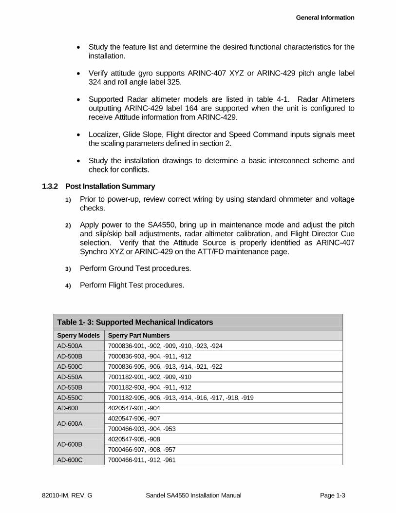
1.3.2 Post Installation Summary 1) Prior to power-up, review correct wiring by using standard ohmmeter and voltage
checks.
2) Apply power to the SA4550, bring up in maintenance mode and adjust the pitch and slip/skip ball adjustments, radar altimeter calibration, and Flight Director Cue selection. Verify that the Attitude Source is properly identified as ARINC-407 Synchro XYZ or ARINC-429 on the ATT/FD maintenance page.
3) Perform Ground Test procedures.
4) Perform Flight Test procedures.
Table 1- 3: Supported Mechanical Indicators Sperry Models Sperry Part Numbers
AD-500A 7000836-901, -902, -909, -910, -923, -924 AD-500B 7000836-903, -904, -911, -912 AD-500C 7000836-905, -906, -913, -914, -921, -922 AD-550A 7001182-901, -902, -909, -910 AD-550B 7001182-903, -904, -911, -912 AD-550C 7001182-905, -906, -913, -914, -916, -917, -918, -919 AD-600 4020547-901, -904
AD-600A 4020547-906, -907 7000466-903, -904, -953
AD-600B 4020547-905, -908 7000466-907, -908, -957
AD-600C 7000466-911, -912, -961
General Information
82010-IM, REV. G Sandel SA4550 Installation Manual Page 1-4
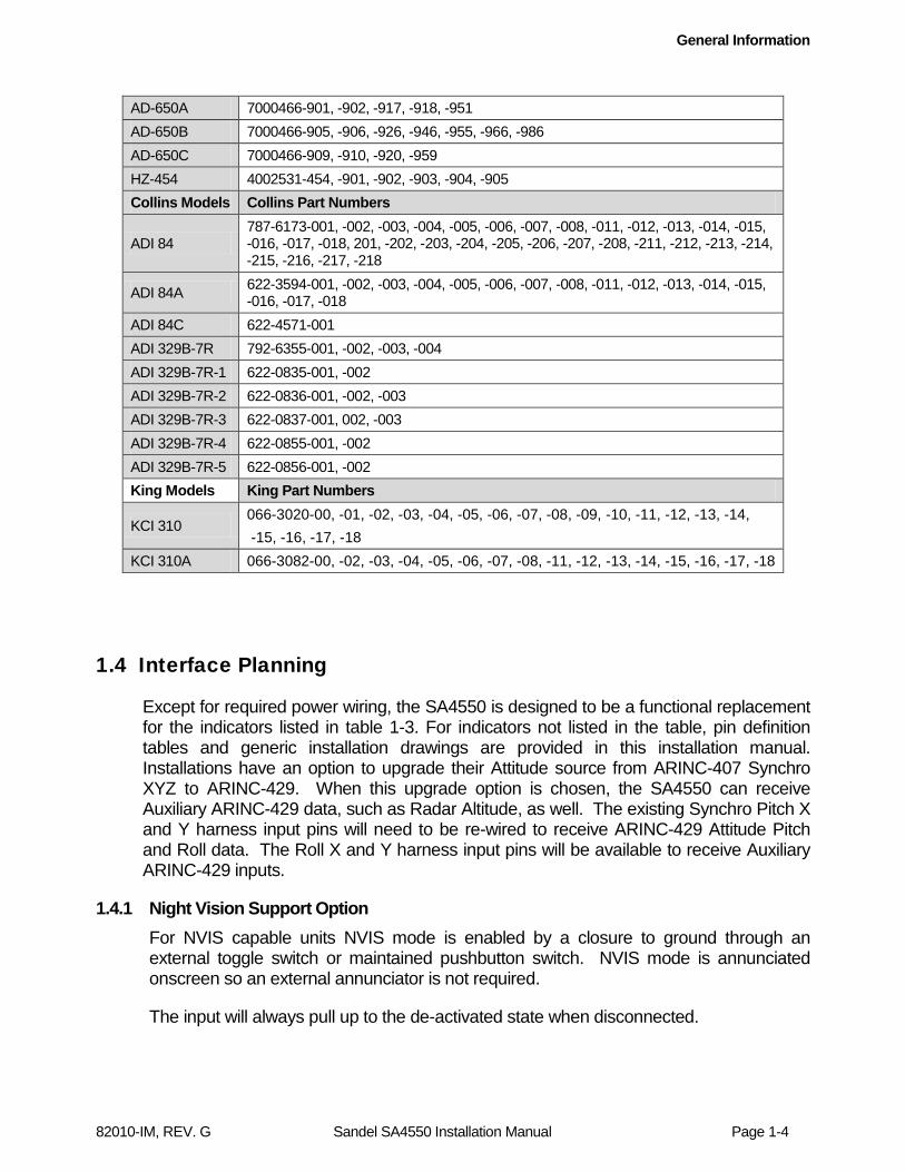
AD-650A 7000466-901, -902, -917, -918, -951 AD-650B 7000466-905, -906, -926, -946, -955, -966, -986 AD-650C 7000466-909, -910, -920, -959 HZ-454 4002531-454, -901, -902, -903, -904, -905 Collins Models Collins Part Numbers
ADI 84 787-6173-001, -002, -003, -004, -005, -006, -007, -008, -011, -012, -013, -014, -015, -016, -017, -018, 201, -202, -203, -204, -205, -206, -207, -208, -211, -212, -213, -214, -215, -216, -217, -218
ADI 84A 622-3594-001, -002, -003, -004, -005, -006, -007, -008, -011, -012, -013, -014, -015, -016, -017, -018
ADI 84C 622-4571-001 ADI 329B-7R 792-6355-001, -002, -003, -004 ADI 329B-7R-1 622-0835-001, -002 ADI 329B-7R-2 622-0836-001, -002, -003 ADI 329B-7R-3 622-0837-001, 002, -003 ADI 329B-7R-4 622-0855-001, -002 ADI 329B-7R-5 622-0856-001, -002 King Models King Part Numbers
KCI 310 066-3020-00, -01, -02, -03, -04, -05, -06, -07, -08, -09, -10, -11, -12, -13, -14, -15, -16, -17, -18
KCI 310A 066-3082-00, -02, -03, -04, -05, -06, -07, -08, -11, -12, -13, -14, -15, -16, -17, -18
1.4 Interface Planning
Except for required power wiring, the SA4550 is designed to be a functional replacement for the indicators listed in table 1-3. For indicators not listed in the table, pin definition tables and generic installation drawings are provided in this installation manual. Installations have an option to upgrade their Attitude source from ARINC-407 Synchro XYZ to ARINC-429. When this upgrade option is chosen, the SA4550 can receive Auxiliary ARINC-429 data, such as Radar Altitude, as well. The existing Synchro Pitch X and Y harness input pins will need to be re-wired to receive ARINC-429 Attitude Pitch and Roll data. The Roll X and Y harness input pins will be available to receive Auxiliary ARINC-429 inputs.
1.4.1 Night Vision Support Option For NVIS capable units NVIS mode is enabled by a closure to ground through an external toggle switch or maintained pushbutton switch. NVIS mode is annunciated onscreen so an external annunciator is not required.
The input will always pull up to the de-activated state when disconnected.

General Information
82010-IM, REV. G Sandel SA4550 Installation Manual Page 1-5
1.5 Disclaimer
Sandel Avionics does not assume any risk for nor accept any responsibility for the interface descriptions contained within this Installation Manual. It is the responsibility of the installer to ensure that such equipment is compatible with the SA4550 as described, and to ensure that the installation of the SA4550 is accomplished with such equipment using the specific equipment manufacturer’s installation and technical instructions. No other representations are expressed herein.
Technical Information
82010-IM, REV. G Sandel SA4550 Installation Manual Page 2-1
2 Technical Information
2.1 General
The SA4550 is enclosed in an ARINC 408, 4ATI form factor enclosure and is mounted to an instrument panel using a standard ATI clamp.
The SA4550 operates on an input voltage from 20 to 33 Volts DC, nominal 40 watts. 26 Volts AC 400 Hertz reference excitation inputs with a current requirement of less than 1 milliampere
The following section describes the technical characteristics that include the appliance approval basis, physical and electrical properties, electrical connector pin allocation which details function and gradient or equipment protocol, and ARINC label support. Also included is the description of the SA4550 installation components, other equipment and installation requirements. A review of the installation approval procedures is provided for filing with authorities.
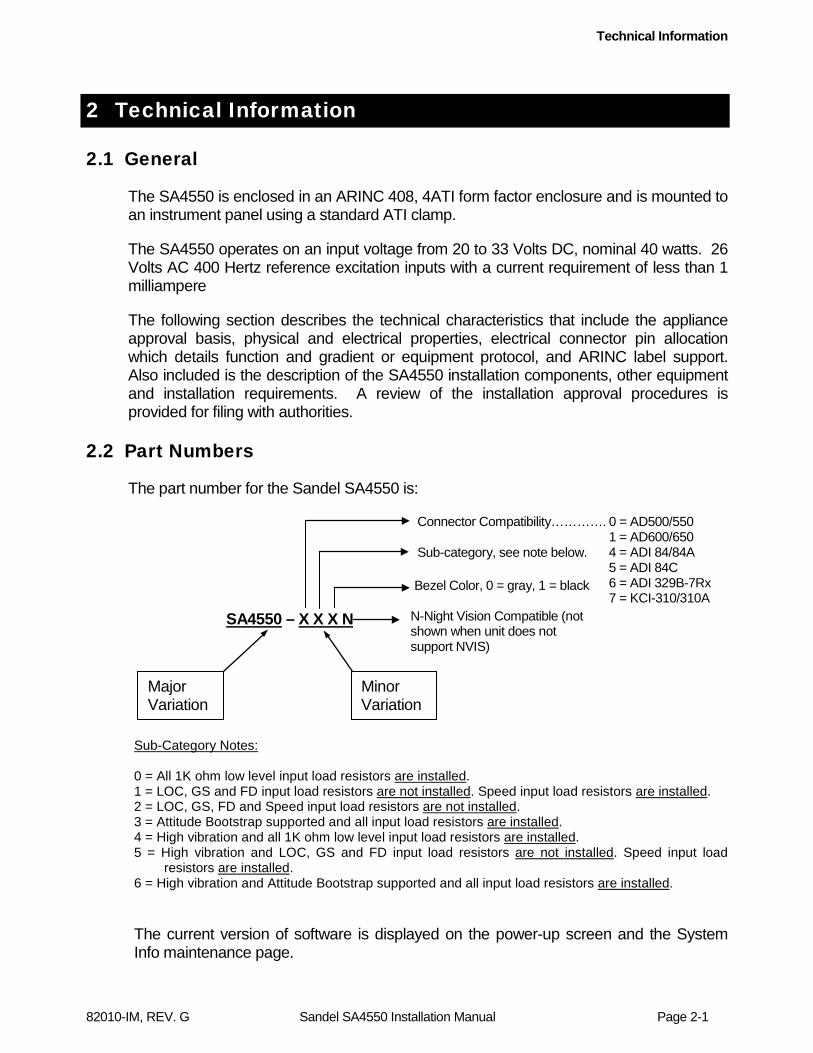
2.2 Part Numbers
The part number for the Sandel SA4550 is:
Sub-Category Notes: 0 = All 1K ohm low level input load resistors are installed. 1 = LOC, GS and FD input load resistors are not installed. Speed input load resistors are installed. 2 = LOC, GS, FD and Speed input load resistors are not installed. 3 = Attitude Bootstrap supported and all input load resistors are installed. 4 = High vibration and all 1K ohm low level input load resistors are installed. 5 = High vibration and LOC, GS and FD input load resistors are not installed. Speed input load
resistors are installed. 6 = High vibration and Attitude Bootstrap supported and all input load resistors are installed.
The current version of software is displayed on the power-up screen and the System Info maintenance page.
Major Variation
Minor Variation
SA4550 – X X X N
Sub-category, see note below.
Connector Compatibility…………. 0 = AD500/550 1 = AD600/650
4 = ADI 84/84A 5 = ADI 84C 6 = ADI 329B-7Rx 7 = KCI-310/310A
Bezel Color, 0 = gray, 1 = black
N-Night Vision Compatible (not shown when unit does not support NVIS)

Technical Information
82010-IM, REV. G Sandel SA4550 Installation Manual Page 2-2
2.2.1 Installation Kit and Accessories
SPN Description 90175-IK SA4550 installation kit 61277 4ATI to 5ATI Adapter Plate Kit 61228 4ATI to 4X5ATI Adapter Plate Kit
2.2.2 Bill of Materials – SA4550 Install Kit
SPN Description Qty
32089 Conn., D – 15 with pins (Positronics P/N DD15F10JVL00) 1
61186 4ATI Mounting Clamp 1 82010-IM Installation Manual, SA4550 1 88114 USB Cable 1
2.3 Approval Summary
2.3.1 License Requirements None.
2.3.2 Approval Data Technical Standard Order: C113: Airborne Multipurpose Electronic Displays C3d: Turn and Slip Instruments C4c: Bank and Pitch Instruments C34e: ILS Glide Slope Receiving Equipment C36e: Airborne ILS Localizer Receiving Equipment C52b: Flight Director Equipment Software Certification: RTCA/DO-178B, Levels A, C Hardware Certification: RTCA/DO-254, Levels A, C Environmental Categories: RTCA/DO-160E (Note: Pitch and Roll attitude are level A. Guidance and Slip / Skid ball are level C.)

Technical Information
82010-IM, REV. G Sandel SA4550 Installation Manual Page 2-3
2.3.3 Technical Standard Order Stipulation
The following stipulation as presented is required by the Federal Aviation Administration for articles approved under a Technical Standard Order. This statement does not preclude multiple installation and operational approvals in regard to specific aircraft make, model, or type:
The conditions and tests required for TSO approval of this article are minimum performance standards. It is the responsibility of those installing this article either on or within a specific type or class of aircraft to determine that the aircraft installation conditions are within the TSO standard. TSO articles must have separate approval for installation in an aircraft. The article may be installed only if performed under 14 CFR part 43 or the applicable airworthiness requirements.
2.3.4 Installation and Operational Approval Procedures For the purpose of seeking installation approval, declarations should be made in the “Description of Work Accomplished” section of a Federal Aviation Administration (FAA) Form 337 or other field approval, or other limited supplemented type certification form. A sample Form 337 is included in Appendix. The basis of approval is for use as a “Primary Attitude Display” for the functions of basic pitch and roll information, flight director command cues, localizer and glide slope deviation, speed command indicator, Slip/Skid indicator, Radar Altimeter display, minimums setting/annunciation, and mode annunciators. Applicable Federal Aviation Regulations (FAR) must be adhered to.
The Environmental Qualification Form for the SA4550 is included in the Appendix, and should be referenced to the categories appropriate to the aircraft type and environment into which the SA4550 is to be installed. The SA4550 was environmentally tested for use in a non-composite aircraft small or large transport aircraft without shielded wiring. The environmental category for the SA4550 should be stipulated on the FAA Form 337, or other approval form.
A “Functional Ground Test Procedures/Report” and an “Operational Flight Check Procedures/Report” is also included in the appendix, and should be used as a basis for validating the SA4550 equipment configuration and for verifying proper installation and functional performance. A copy of this form should be submitted along with the FAA Form 337, or other approval or certification form. A permanent copy must be filed and maintained by the installing agency. Another copy must be presented to the aircraft owner for entry into the aircraft maintenance records, as well as a copy forwarded to Sandel Avionics along with the Warranty Registration Form, Part Number 82010-0137, to be filed after completion and installation acceptance. If any difficulty is experienced with the functionality or operational performance of the SA4550, contact Sandel Avionics for assistance.

Technical Information
82010-IM, REV. G Sandel SA4550 Installation Manual Page 2-4
2.4 Physical, and Electrical Properties
2.4.1 Physical Dimensions . SA4550-(0, 4, 5, 6, 7)XX For detailed dimensional information reference Sandel Drawing 82010-07 “Envelope, SA4550 (AD550)” Reference same drawing for Collins AD 84/84A/84C, 329B-7Rx, and King KCI 310/310A
Form Factor: 4ATI (ARINC 408) Width: 3.975 in. (10.1 cm.)
Height: 3.975 in. (10.1 cm.) Length: 8.15 in. (20.68 cm.) overall flush to bezel;
7.82 in (19.86 cm) measured from rear of bezel. Weight: 3.4 lbs. (1.54 Kg.)
CG: 4.3 in. from rear of bezel. ATI Clamp: Sandel Avionics P/N 61186 or equivalent.
Cooling Requirements: Internal fan requiring ambient air at fan input. SA4550-1XX For detailed dimensional information reference Sandel Drawing 82031-07 “Envelope, SA4550 (AD650)”
Form Factor: 4ATI (ARINC 408) Width: 3.975 in. (10.1 cm.)
Height: 3.975 in. (10.1 cm.) Length: 7.84 in. (19.91 cm.) overall flush to bezel;
7.57 in (19.23 cm) measured from rear of bezel. Weight: 3.4 lbs. (1.54 Kg.)
CG: 4.3 in. from rear of bezel. ATI Clamp: Sandel Avionics P/N 61186 or equivalent.
Cooling Requirements: Internal fan requiring ambient air at fan input.
2.4.2 Summary Operational Characteristics
Temperature Altitude: -20° C to +70° C - up to 55,000 feet Power Inputs: 28 Vdc @ 1.4A nominal (40 watts)
Technical Information
82010-IM, REV. G Sandel SA4550 Installation Manual Page 2-5
2.5 Connector Summary
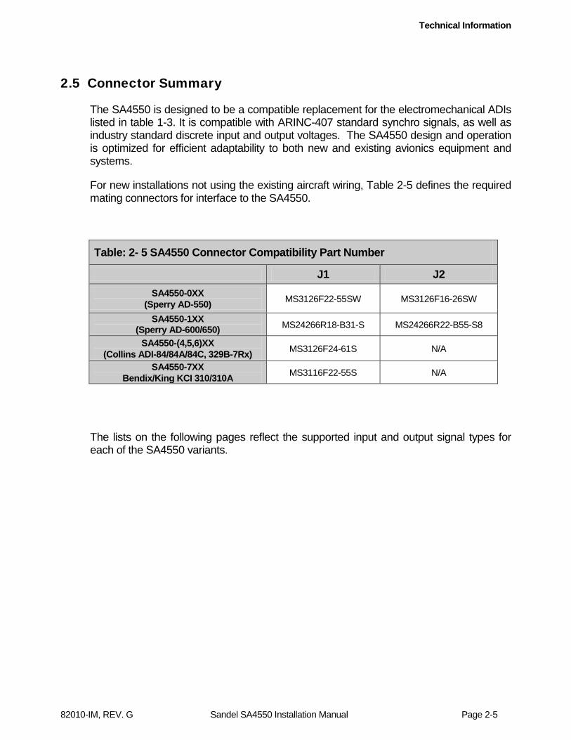
The SA4550 is designed to be a compatible replacement for the electromechanical ADIs listed in table 1-3. It is compatible with ARINC-407 standard synchro signals, as well as industry standard discrete input and output voltages. The SA4550 design and operation is optimized for efficient adaptability to both new and existing avionics equipment and systems.
For new installations not using the existing aircraft wiring, Table 2-5 defines the required mating connectors for interface to the SA4550.
Table: 2- 5 SA4550 Connector Compatibility Part Number
J1 J2 SA4550-0XX
(Sperry AD-550) MS3126F22-55SW MS3126F16-26SW
SA4550-1XX (Sperry AD-600/650) MS24266R18-B31-S MS24266R22-B55-S8
SA4550-(4,5,6)XX (Collins ADI-84/84A/84C, 329B-7Rx) MS3126F24-61S N/A
SA4550-7XX Bendix/King KCI 310/310A MS3116F22-55S N/A
The lists on the following pages reflect the supported input and output signal types for each of the SA4550 variants.

Technical Information
82010-IM, REV. G Sandel SA4550 Installation Manual Page 2-6
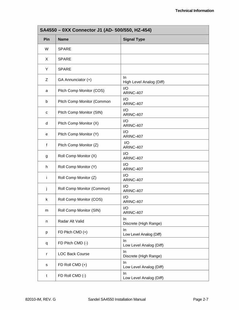
2.5.1 SA4550-0XX Connector J1 – Sperry AD – 500/550, HZ-454
SA4550 – 0XX Connector J1 (AD- 500/550, HZ-454)
Pin Name Signal Type
A ATT Power Input (H) In AC Reference (400 Hz)
B ATT Power Input (C) In AC Reference Common
C Chassis Ground In Case Ground
D Fast/Slow - In Low Level Analog (Diff)
E Roll Data Input (Y) / AUX A429 (B)
In ARINC-407 or ARINC-429
F SPARE
G Roll Data Input (Z) / AUX A429 SHLD GND
In ARINC-407 or ARINC-429
H TEST DISABLE GND In Discrete (High Range)
J RESERVED
K RESERVED
L Roll Data Input (X) / AUX A429 (A)
In ARINC-407 or ARINC-429
M ATT Valid Input (+) In Discrete (High Range)
N Pitch Input Data (X) / ATT A429 (A)
In ARINC-407 or ARINC-429
P DC GND In Power
R RESERVED
S Fast/Slow (+) In Low Level Analog (Diff)
T Pitch Input Data (Z) / ATT A429 SHLD GND
In ARINC-407 or ARINC-429
U Pitch Input Data (Y) / ATT A429 (B)
In ARINC-407 or ARINC-429
V RESERVED
Technical Information
82010-IM, REV. G Sandel SA4550 Installation Manual Page 2-7
SA4550 – 0XX Connector J1 (AD- 500/550, HZ-454)
Pin Name Signal Type
W SPARE
X SPARE
Y SPARE
Z GA Annunciator (+) In High Level Analog (Diff)
a Pitch Comp Monitor (COS) I/O ARINC-407
b Pitch Comp Monitor (Common I/O ARINC-407
c Pitch Comp Monitor (SIN) I/O ARINC-407
d Pitch Comp Monitor (X) I/O ARINC-407
e Pitch Comp Monitor (Y) I/O ARINC-407
f Pitch Comp Monitor (Z) I/O ARINC-407
g Roll Comp Monitor (X) I/O ARINC-407
h Roll Comp Monitor (Y) I/O ARINC-407
i Roll Comp Monitor (Z) I/O ARINC-407
j Roll Comp Monitor (Common) I/O ARINC-407
k Roll Comp Monitor (COS) I/O ARINC-407
m Roll Comp Monitor (SIN) I/O ARINC-407
n Radar Alt Valid In Discrete (High Range)
p FD Pitch CMD (+) In Low Level Analog (Diff)
q FD Pitch CMD (-) In Low Level Analog (Diff)
r LOC Back Course In Discrete (High Range)
s FD Roll CMD (+) In Low Level Analog (Diff)
t FD Roll CMD (-) In Low Level Analog (Diff)
Technical Information
82010-IM, REV. G Sandel SA4550 Installation Manual Page 2-8
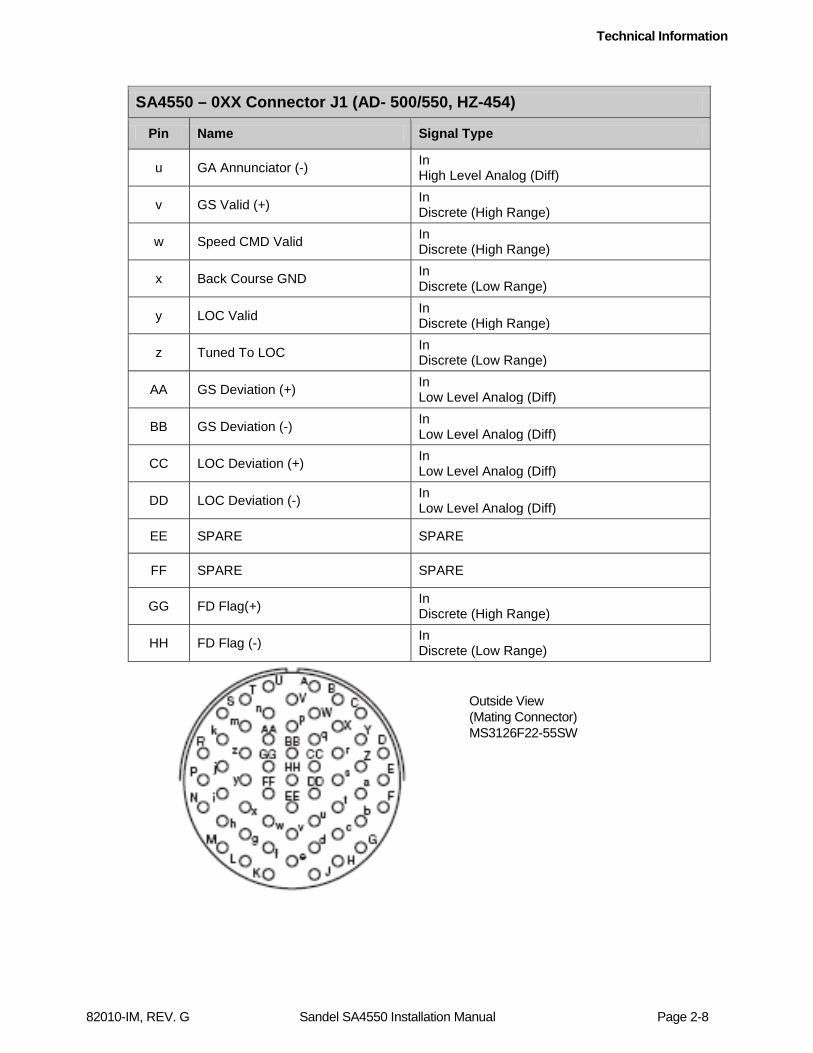
SA4550 – 0XX Connector J1 (AD- 500/550, HZ-454)
Pin Name Signal Type
u GA Annunciator (-) In High Level Analog (Diff)
v GS Valid (+) In Discrete (High Range)
w Speed CMD Valid In Discrete (High Range)
x Back Course GND In Discrete (Low Range)
y LOC Valid In Discrete (High Range)
z Tuned To LOC In Discrete (Low Range)
AA GS Deviation (+) In Low Level Analog (Diff)
BB GS Deviation (-) In Low Level Analog (Diff)
CC LOC Deviation (+) In Low Level Analog (Diff)
DD LOC Deviation (-) In Low Level Analog (Diff)
EE SPARE SPARE
FF SPARE SPARE
GG FD Flag(+) In Discrete (High Range)
HH FD Flag (-) In Discrete (Low Range)
Outside View (Mating Connector) MS3126F22-55SW
Technical Information
82010-IM, REV. G Sandel SA4550 Installation Manual Page 2-9
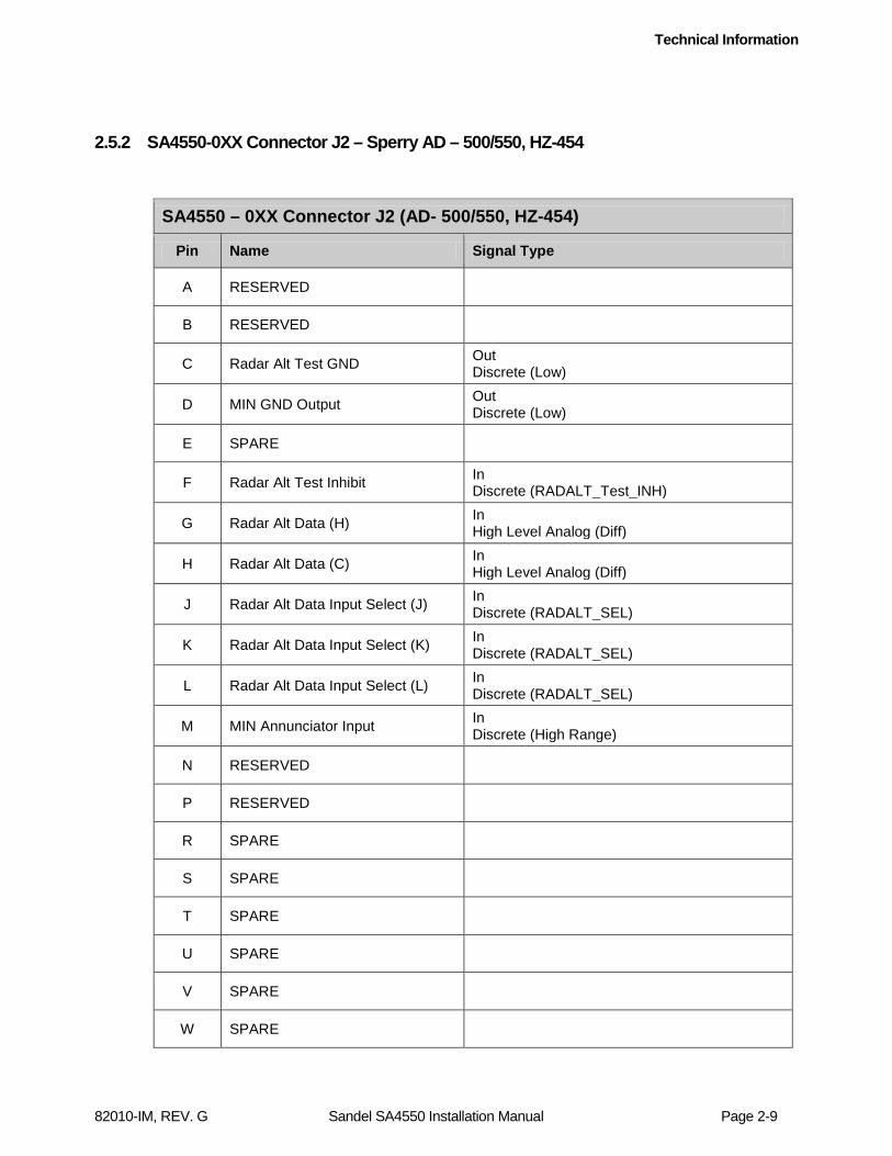
2.5.2 SA4550-0XX Connector J2 – Sperry AD – 500/550, HZ-454
SA4550 – 0XX Connector J2 (AD- 500/550, HZ-454)
Pin Name Signal Type
A RESERVED
B RESERVED
C Radar Alt Test GND Out Discrete (Low)
D MIN GND Output Out Discrete (Low)
E SPARE
F Radar Alt Test Inhibit In Discrete (RADALT_Test_INH)
G Radar Alt Data (H) In High Level Analog (Diff)
H Radar Alt Data (C) In High Level Analog (Diff)
J Radar Alt Data Input Select (J) In Discrete (RADALT_SEL)
K Radar Alt Data Input Select (K) In Discrete (RADALT_SEL)
L Radar Alt Data Input Select (L) In Discrete (RADALT_SEL)
M MIN Annunciator Input In Discrete (High Range)
N RESERVED
P RESERVED
R SPARE
S SPARE
T SPARE
U SPARE
V SPARE
W SPARE

Technical Information
82010-IM, REV. G Sandel SA4550 Installation Manual Page 2-10
SA4550 – 0XX Connector J2 (AD- 500/550, HZ-454)
Pin Name Signal Type
X SPARE
Y SPARE
Z SPARE
a SPARE
b SPARE
c SPARE
Outside View (Mating Connector) MS3126F16-26SW

Technical Information
82010-IM, REV. G Sandel SA4550 Installation Manual Page 2-11
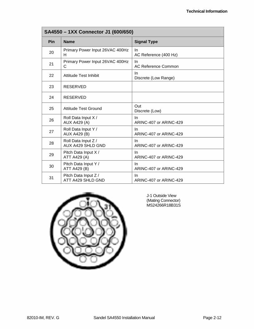
2.5.3 SA4550-1XX Connector J1 – Sperry AD – 600/ 650
SA4550 – 1XX Connector J1 (600/650)
Pin Name Signal Type
1 Pitch Comp Monitor X In ARINC-407
2 Pitch Comp Monitor Y In ARINC-407
3 Pitch Comp Monitor Z In ARINC-407
4 Pitch Comp Monitor COS H Out ARINC-407
5 Pitch Comp Monitor COS C Out ARINC-407
6 Pitch Comp Monitor SIN H Out ARINC-407
7 Pitch Comp Monitor SIN C Out ARINC-407
8 Spare
9 Spare
10 Attitude Valid Input In Discrete (High Range)
11 Tuned To LOC GROUND In Discrete (Low Range)
12 Roll Comp Monitor COS H Out ARINC-407
13 Roll Comp Monitor COS C Out ARINC-407
14 Roll Comp Monitor SIN H Out ARINC-407
15 Roll Comp Monitor SIN C Out ARINC-407
16 Roll Comp Monitor X In ARINC-407
17 Roll Comp Monitor Y In ARINC-407
18 Roll Comp Monitor Z In ARINC-407
19 Spare
Technical Information
82010-IM, REV. G Sandel SA4550 Installation Manual Page 2-12
SA4550 – 1XX Connector J1 (600/650)
Pin Name Signal Type
20 Primary Power Input 26VAC 400Hz H
In AC Reference (400 Hz)
21 Primary Power Input 26VAC 400Hz C
In AC Reference Common
22 Attitude Test Inhibit In Discrete (Low Range)
23 RESERVED
24 RESERVED
25 Attitude Test Ground Out Discrete (Low)
26 Roll Data Input X / AUX A429 (A)
In ARINC-407 or ARINC-429
27 Roll Data Input Y / AUX A429 (B)
In ARINC-407 or ARINC-429
28 Roll Data Input Z / AUX A429 SHLD GND
In ARINC-407 or ARINC-429
29 Pitch Data Input X / ATT A429 (A)
In ARINC-407 or ARINC-429
30 Pitch Data Input Y / ATT A429 (B)
In ARINC-407 or ARINC-429
31 Pitch Data Input Z / ATT A429 SHLD GND
In ARINC-407 or ARINC-429
J-1 Outside View (Mating Connector) MS24266R18B31S

Technical Information
82010-IM, REV. G Sandel SA4550 Installation Manual Page 2-13
2.5.4 SA4550-1XX Connector J2 – Sperry AD-600/ 650
SA4550 – 1XX Connector J2 (600/650) Pin Name Signal Type
1 Radar Alt Select Common In Ground
2 FD Flag Valid + In High Level Analog (Diff)
3 FD Flag Valid - In High Level Analog (Diff)
4 Spare
5 Radar Alt Valid + In Discrete (High Range)
6 Radar Alt ARINC Select In Discrete (RADALT_SEL)
7 LOC Valid In Discrete (High Range)
8 Radar Alt Aux Select In Discrete (RADALT_SEL)
9 SPD Annunciator In Discrete (FPGA)
10 VRT Annunciator In Discrete (FPGA)
11 VN Annunciator In Discrete (FPGA)
12 Radar Alt Test Out Discrete (Low)
13 RESERVED 14 RESERVED
15 Speed Cmd +Up In Low Level Analog (Diff)
16 Speed Cmd +Down In Low Level Analog (Diff)
17 RESERVED
18 GS Deviation +Up In Low Level Analog (Diff)
19 GS Deviation +Down In Low Level Analog (Diff)
20 GS Flag Valid + In High Level Analog (Diff)
21 GS Flag Valid - In High Level Analog (Diff)
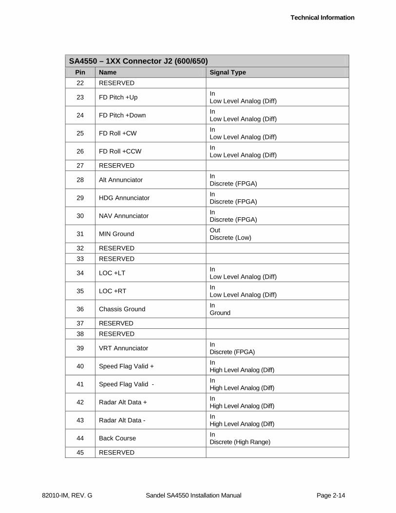
Technical Information
82010-IM, REV. G Sandel SA4550 Installation Manual Page 2-14
SA4550 – 1XX Connector J2 (600/650) Pin Name Signal Type 22 RESERVED
23 FD Pitch +Up In Low Level Analog (Diff)
24 FD Pitch +Down In Low Level Analog (Diff)
25 FD Roll +CW In Low Level Analog (Diff)
26 FD Roll +CCW In Low Level Analog (Diff)
27 RESERVED
28 Alt Annunciator In Discrete (FPGA)
29 HDG Annunciator In Discrete (FPGA)
30 NAV Annunciator In Discrete (FPGA)
31 MIN Ground Out Discrete (Low)
32 RESERVED 33 RESERVED
34 LOC +LT In Low Level Analog (Diff)
35 LOC +RT In Low Level Analog (Diff)
36 Chassis Ground In Ground
37 RESERVED 38 RESERVED
39 VRT Annunciator In Discrete (FPGA)
40 Speed Flag Valid + In High Level Analog (Diff)
41 Speed Flag Valid - In High Level Analog (Diff)
42 Radar Alt Data + In High Level Analog (Diff)
43 Radar Alt Data - In High Level Analog (Diff)
44 Back Course In Discrete (High Range)
45 RESERVED
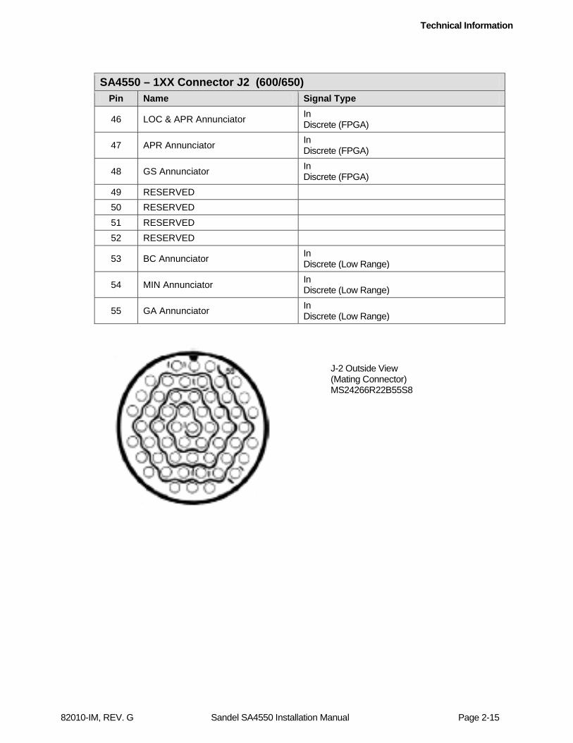
Technical Information
82010-IM, REV. G Sandel SA4550 Installation Manual Page 2-15
J-2 Outside View (Mating Connector) MS24266R22B55S8
SA4550 – 1XX Connector J2 (600/650) Pin Name Signal Type
46 LOC & APR Annunciator In Discrete (FPGA)
47 APR Annunciator In Discrete (FPGA)
48 GS Annunciator In Discrete (FPGA)
49 RESERVED 50 RESERVED 51 RESERVED 52 RESERVED
53 BC Annunciator In Discrete (Low Range)
54 MIN Annunciator In Discrete (Low Range)
55 GA Annunciator In Discrete (Low Range)
Technical Information
82010-IM, REV. G Sandel SA4550 Installation Manual Page 2-16
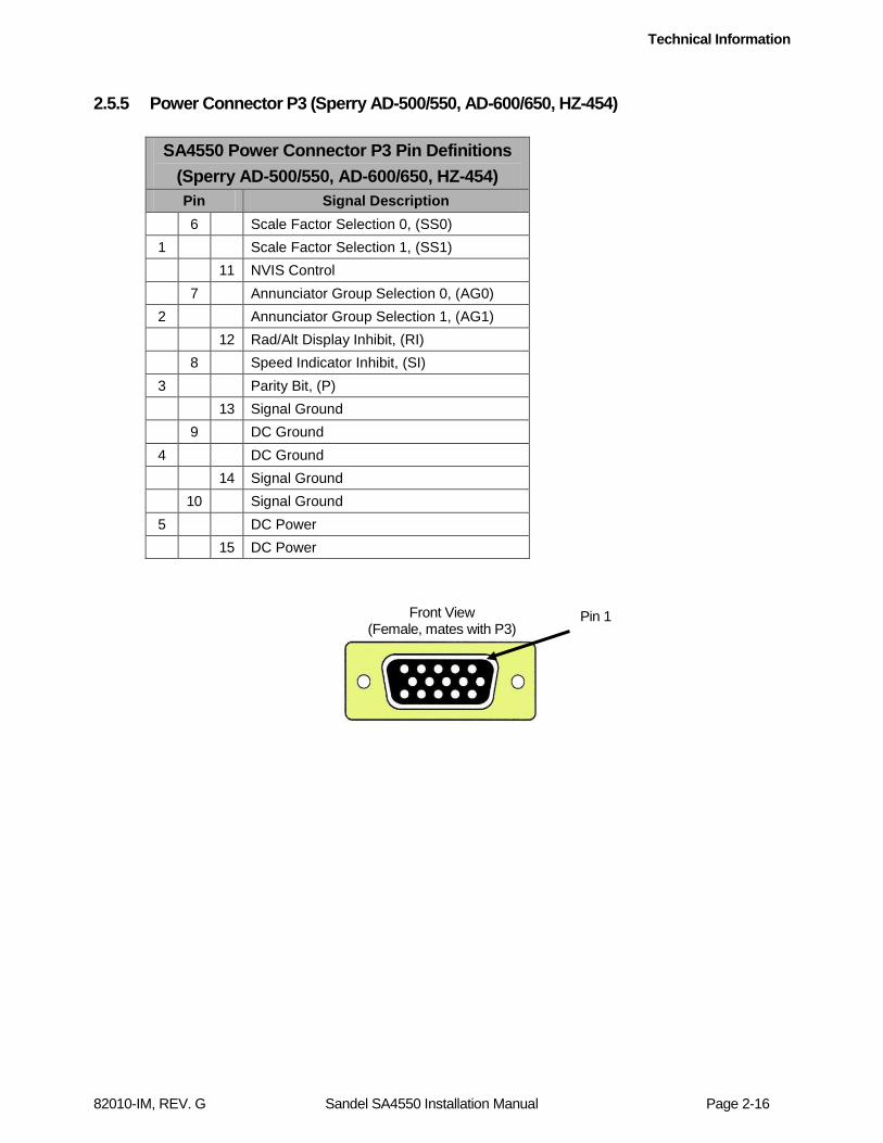
2.5.5 Power Connector P3 (Sperry AD-500/550, AD-600/650, HZ-454)
SA4550 Power Connector P3 Pin Definitions (Sperry AD-500/550, AD-600/650, HZ-454) Pin Signal Description
6 Scale Factor Selection 0, (SS0) 1 Scale Factor Selection 1, (SS1) 11 NVIS Control 7 Annunciator Group Selection 0, (AG0) 2 Annunciator Group Selection 1, (AG1) 12 Rad/Alt Display Inhibit, (RI) 8 Speed Indicator Inhibit, (SI) 3 Parity Bit, (P) 13 Signal Ground 9 DC Ground 4 DC Ground 14 Signal Ground 10 Signal Ground 5 DC Power 15 DC Power
Front View (Female, mates with P3)
Pin 1
Technical Information
82010-IM, REV. G Sandel SA4550 Installation Manual Page 2-17
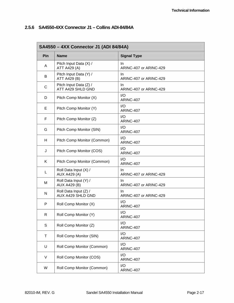
2.5.6 SA4550-4XX Connector J1 – Collins ADI-84/84A
SA4550 – 4XX Connector J1 (ADI 84/84A)
Pin Name Signal Type
A Pitch Input Data (X) / ATT A429 (A)
In ARINC-407 or ARINC-429
B Pitch Input Data (Y) / ATT A429 (B)
In ARINC-407 or ARINC-429
C Pitch Input Data (Z) / ATT A429 SHLD GND
In ARINC-407 or ARINC-429
D Pitch Comp Monitor (X) I/O ARINC-407
E Pitch Comp Monitor (Y) I/O ARINC-407
F Pitch Comp Monitor (Z) I/O ARINC-407
G Pitch Comp Monitor (SIN) I/O ARINC-407
H Pitch Comp Monitor (Common) I/O ARINC-407
J Pitch Comp Monitor (COS) I/O ARINC-407
K Pitch Comp Monitor (Common) I/O ARINC-407
L Roll Data Input (X) / AUX A429 (A)
In ARINC-407 or ARINC-429
M Roll Data Input (Y) / AUX A429 (B)
In ARINC-407 or ARINC-429
N Roll Data Input (Z) / AUX A429 SHLD GND
In ARINC-407 or ARINC-429
P Roll Comp Monitor (X) I/O ARINC-407
R Roll Comp Monitor (Y) I/O ARINC-407
S Roll Comp Monitor (Z) I/O ARINC-407
T Roll Comp Monitor (SIN) I/O ARINC-407
U Roll Comp Monitor (Common) I/O ARINC-407
V Roll Comp Monitor (COS) I/O ARINC-407
W Roll Comp Monitor (Common) I/O ARINC-407
Technical Information
82010-IM, REV. G Sandel SA4550 Installation Manual Page 2-18
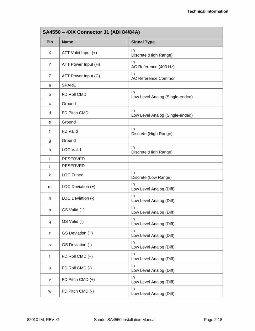
SA4550 – 4XX Connector J1 (ADI 84/84A)
Pin Name Signal Type
X ATT Valid Input (+) In Discrete (High Range)
Y ATT Power Input (H) In AC Reference (400 Hz)
Z ATT Power Input (C) In AC Reference Common
a SPARE
b FD Roll CMD In Low Level Analog (Single-ended)
c Ground
d FD Pitch CMD In Low Level Analog (Single-ended)
e Ground
f FD Valid In Discrete (High Range)
g Ground
h LOC Valid In Discrete (High Range)
i RESERVED j RESERVED
k LOC Tuned In Discrete (Low Range)
m LOC Deviation (+) In Low Level Analog (Diff)
n LOC Deviation (-) In Low Level Analog (Diff)
p GS Valid (+) In Low Level Analog (Diff)
q GS Valid (-) In Low Level Analog (Diff)
r GS Deviation (+) In Low Level Analog (Diff)
s GS Deviation (-) In Low Level Analog (Diff)
t FD Roll CMD (+) In Low Level Analog (Diff)
u FD Roll CMD (-) In Low Level Analog (Diff)
v FD Pitch CMD (+) In Low Level Analog (Diff)
w FD Pitch CMD (-) In Low Level Analog (Diff)

Technical Information
82010-IM, REV. G Sandel SA4550 Installation Manual Page 2-19
SA4550 – 4XX Connector J1 (ADI 84/84A)
Pin Name Signal Type
x RADALT VALID (+) In High Level Analog (Diff)
y RADALT VALID (-) In High Level Analog (Diff)
z Radar Alt Data (H) In High Level Analog (Diff)
AA Radar Alt Data (C) In High Level Analog (Diff)
BB FD Bars In-View In Discrete (High Range)
CC FD Bars Out of View In Discrete (High Range)
DD RESERVED EE RESERVED
FF FD Pitch CMD output Out Analog
GG SPARE HH SPARE
JJ FD Roll CMD output Out Analog
KK FD Roll CMD In Low Level Analog (Single-ended)
LL FD Pitch CMD In Low Level Analog (Single-ended)
MM Annunciator Excitation In Discrete (Low Range)
NN DH Annunciator In Discrete (Low Range)
PP SPARE
Outside View (Mating Connector) MS3126F24-61S
Technical Information
82010-IM, REV. G Sandel SA4550 Installation Manual Page 2-20
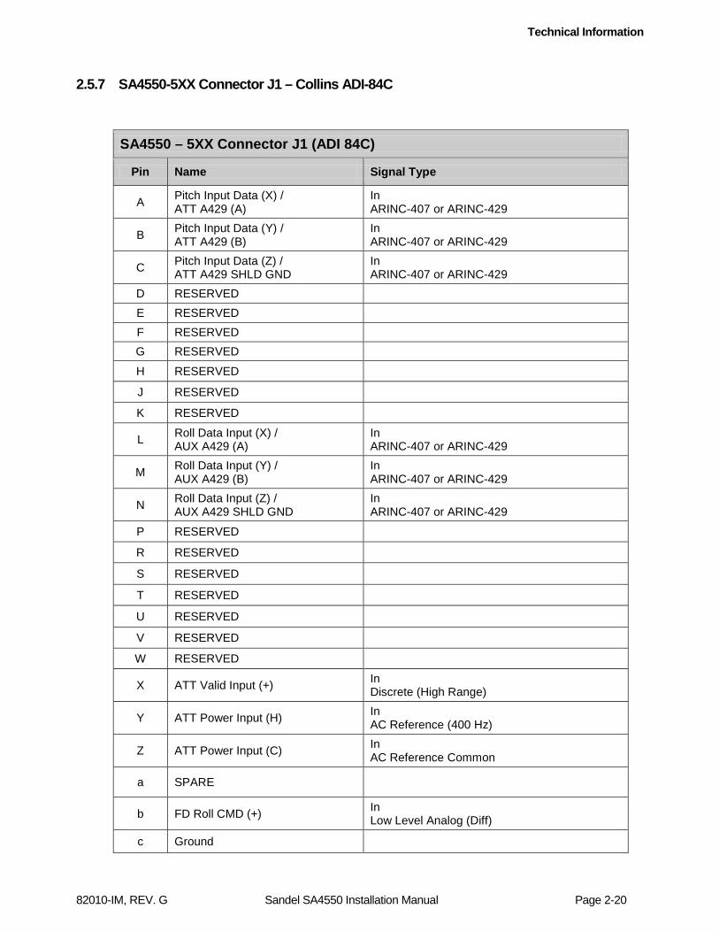
2.5.7 SA4550-5XX Connector J1 – Collins ADI-84C
SA4550 – 5XX Connector J1 (ADI 84C)
Pin Name Signal Type
A Pitch Input Data (X) / ATT A429 (A)
In ARINC-407 or ARINC-429
B Pitch Input Data (Y) / ATT A429 (B)
In ARINC-407 or ARINC-429
C Pitch Input Data (Z) / ATT A429 SHLD GND
In ARINC-407 or ARINC-429
D RESERVED E RESERVED F RESERVED G RESERVED
H RESERVED
J RESERVED
K RESERVED
L Roll Data Input (X) / AUX A429 (A)
In ARINC-407 or ARINC-429
M Roll Data Input (Y) / AUX A429 (B)
In ARINC-407 or ARINC-429
N Roll Data Input (Z) / AUX A429 SHLD GND
In ARINC-407 or ARINC-429
P RESERVED
R RESERVED
S RESERVED
T RESERVED
U RESERVED
V RESERVED
W RESERVED
X ATT Valid Input (+) In Discrete (High Range)
Y ATT Power Input (H) In AC Reference (400 Hz)
Z ATT Power Input (C) In AC Reference Common
a SPARE
b FD Roll CMD (+) In Low Level Analog (Diff)
c Ground

Technical Information
82010-IM, REV. G Sandel SA4550 Installation Manual Page 2-21
SA4550 – 5XX Connector J1 (ADI 84C)
Pin Name Signal Type
d FD Pitch CMD (+) In Low Level Analog (Diff)
e Ground
f FD Valid In Discrete (High Range)
g Ground
h LOC Valid In Discrete (High Range)
i RESERVED
j RESERVED
k LOC Tuned In Discrete (Low Range)
m LOC Deviation (+) In Low Level Analog (Diff)
n LOC Deviation (-) In Low Level Analog (Diff)
p GS Valid (+) In Low Level Analog (Diff)
q GS Valid (-) In Low Level Analog (Diff)
r GS Deviation (+) In Low Level Analog (Diff)
s GS Deviation (-) In Low Level Analog (Diff)
t RESERVED
u RESERVED
v RESERVED
w RESERVED
x RADALT VALID (+) In High Level Analog (Diff)
y RADALT VALID (-) In High Level Analog (Diff)
z Radar Alt Data (H) In High Level Analog (Diff)
AA Radar Alt Data (C) In High Level Analog (Diff)
BB FD Bars In-View In Discrete (High Range)
CC FD Bars Out of View In Discrete (High Range)

Technical Information
82010-IM, REV. G Sandel SA4550 Installation Manual Page 2-22
SA4550 – 5XX Connector J1 (ADI 84C)
Pin Name Signal Type
DD FD Pitch CMD (-) In Low Level Analog (Diff)
EE FD Roll CMD (-) In Low Level Analog (Diff)
FF RESERVED
GG SPARE
HH SPARE
JJ RESERVED
KK RESERVED
LL RESERVED
MM Annunciator Excitation In Discrete (Low Range)
NN GA Annunciator In Discrete (Low Range)
PP SPARE
Outside View (Mating Connector) MS3126F24-61S
Technical Information
82010-IM, REV. G Sandel SA4550 Installation Manual Page 2-23
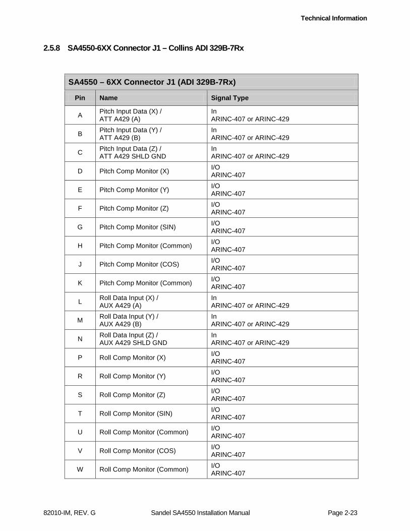
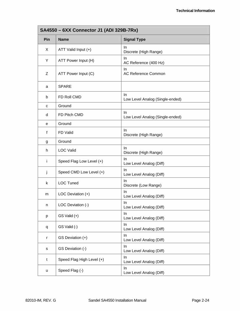
2.5.8 SA4550-6XX Connector J1 – Collins ADI 329B-7Rx
SA4550 – 6XX Connector J1 (ADI 329B-7Rx)
Pin Name Signal Type
A Pitch Input Data (X) / ATT A429 (A)
In ARINC-407 or ARINC-429
B Pitch Input Data (Y) / ATT A429 (B)
In ARINC-407 or ARINC-429
C Pitch Input Data (Z) / ATT A429 SHLD GND
In ARINC-407 or ARINC-429
D Pitch Comp Monitor (X) I/O ARINC-407
E Pitch Comp Monitor (Y) I/O ARINC-407
F Pitch Comp Monitor (Z) I/O ARINC-407
G Pitch Comp Monitor (SIN) I/O ARINC-407
H Pitch Comp Monitor (Common) I/O ARINC-407
J Pitch Comp Monitor (COS) I/O ARINC-407
K Pitch Comp Monitor (Common) I/O ARINC-407
L Roll Data Input (X) / AUX A429 (A)
In ARINC-407 or ARINC-429
M Roll Data Input (Y) / AUX A429 (B)
In ARINC-407 or ARINC-429
N Roll Data Input (Z) / AUX A429 SHLD GND
In ARINC-407 or ARINC-429
P Roll Comp Monitor (X) I/O ARINC-407
R Roll Comp Monitor (Y) I/O ARINC-407
S Roll Comp Monitor (Z) I/O ARINC-407
T Roll Comp Monitor (SIN) I/O ARINC-407
U Roll Comp Monitor (Common) I/O ARINC-407
V Roll Comp Monitor (COS) I/O ARINC-407
W Roll Comp Monitor (Common) I/O ARINC-407
Technical Information
82010-IM, REV. G Sandel SA4550 Installation Manual Page 2-24
SA4550 – 6XX Connector J1 (ADI 329B-7Rx)
Pin Name Signal Type
X ATT Valid Input (+) In Discrete (High Range)
Y ATT Power Input (H) In AC Reference (400 Hz)
Z ATT Power Input (C) In AC Reference Common
a SPARE
b FD Roll CMD In Low Level Analog (Single-ended)
c Ground
d FD Pitch CMD In Low Level Analog (Single-ended)
e Ground
f FD Valid In Discrete (High Range)
g Ground
h LOC Valid In Discrete (High Range)
i Speed Flag Low Level (+) In Low Level Analog (Diff)
j Speed CMD Low Level (+) In Low Level Analog (Diff)
k LOC Tuned In Discrete (Low Range)
m LOC Deviation (+) In Low Level Analog (Diff)
n LOC Deviation (-) In Low Level Analog (Diff)
p GS Valid (+) In Low Level Analog (Diff)
q GS Valid (-) In Low Level Analog (Diff)
r GS Deviation (+) In Low Level Analog (Diff)
s GS Deviation (-) In Low Level Analog (Diff)
t Speed Flag High Level (+) In Low Level Analog (Diff)
u Speed Flag (-) In Low Level Analog (Diff)
Technical Information
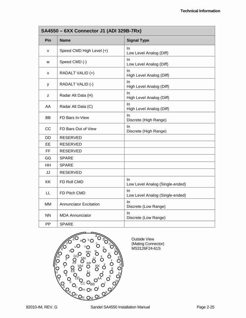
82010-IM, REV. G Sandel SA4550 Installation Manual Page 2-25
SA4550 – 6XX Connector J1 (ADI 329B-7Rx)
Pin Name Signal Type
v Speed CMD High Level (+) In Low Level Analog (Diff)
w Speed CMD (-) In Low Level Analog (Diff)
x RADALT VALID (+) In High Level Analog (Diff)
y RADALT VALID (-) In High Level Analog (Diff)
z Radar Alt Data (H) In High Level Analog (Diff)
AA Radar Alt Data (C) In High Level Analog (Diff)
BB FD Bars In-View In Discrete (High Range)
CC FD Bars Out of View In Discrete (High Range)
DD RESERVED EE RESERVED
FF RESERVED
GG SPARE
HH SPARE
JJ RESERVED
KK FD Roll CMD In Low Level Analog (Single-ended)
LL FD Pitch CMD In Low Level Analog (Single-ended)
MM Annunciator Excitation In Discrete (Low Range)
NN MDA Annunciator In Discrete (Low Range)
PP SPARE
Outside View (Mating Connector) MS3126F24-61S
Technical Information
82010-IM, REV. G Sandel SA4550 Installation Manual Page 2-26
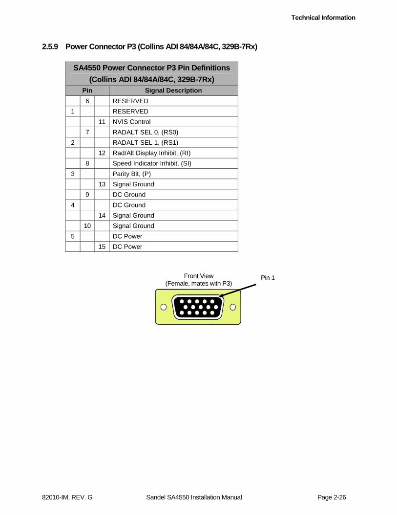
2.5.9 Power Connector P3 (Collins ADI 84/84A/84C, 329B-7Rx)
SA4550 Power Connector P3 Pin Definitions (Collins ADI 84/84A/84C, 329B-7Rx)
Pin Signal Description 6 RESERVED 1 RESERVED 11 NVIS Control 7 RADALT SEL 0, (RS0) 2 RADALT SEL 1, (RS1) 12 Rad/Alt Display Inhibit, (RI) 8 Speed Indicator Inhibit, (SI) 3 Parity Bit, (P) 13 Signal Ground 9 DC Ground 4 DC Ground 14 Signal Ground 10 Signal Ground 5 DC Power 15 DC Power
Front View (Female, mates with P3)
Pin 1

Technical Information
82010-IM, REV. G Sandel SA4550 Installation Manual Page 2-27
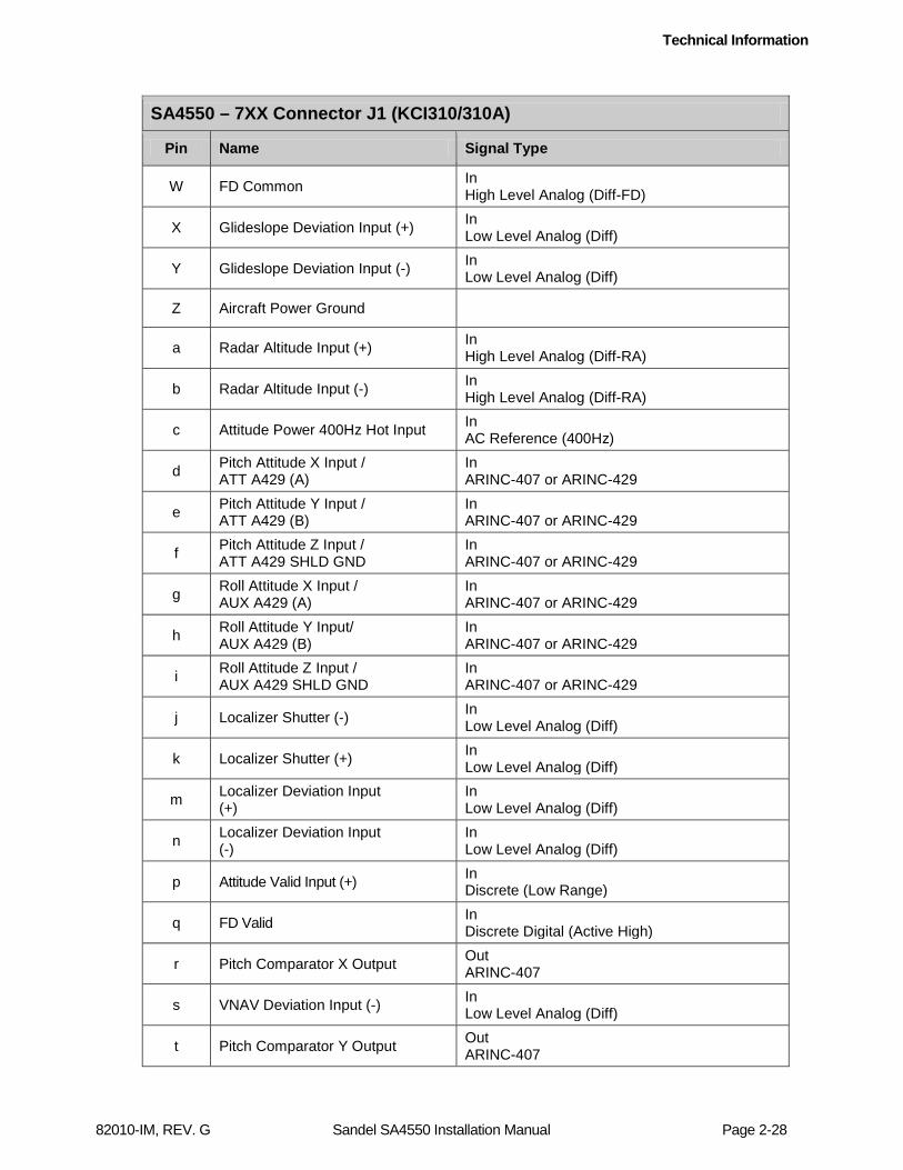
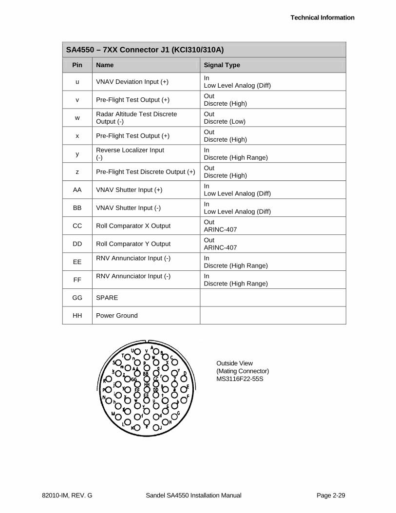
2.5.10 SA4550-7XX Connector J1 (King KCI 310/310A)
SA4550 – 7XX Connector J1 (KCI310/310A)
Pin Name Signal Type
A DH Discrete Output (-) Out Discrete (Low)
B Lighting Common In High Level Analog (Diff)
C 5V DC/AC Lighting Input In High Level Analog (Diff-5V_Lighting)
D DH Annunciator Input (-) In Discrete (High Range)
E 28VDC Lighting Input In High Level Analog (Diff-28V_Lighting)
F MDA Annunciator Input (-) In Discrete (High Range)
G ANG Annunciator Input (-) In Discrete (High Range)
H RADALT Test-Aid (-) (B/K KRA-405/405B)
Out Discrete (RA_Test-Aid)
J Radar Altitude Valid Input (+) In Discrete (High Range)
K Glideslope Shutter (-) In Low Level Analog (Diff)
L Glideslope Shutter (+) In Low Level Analog (Diff)
M Localizer Energized Input (-) In Discrete (High Range)
N Annunciator Excitation Input In Discrete (Low Range)
P FD Pitch Steering Command Input In High Level Analog (Diff-FD)
R Command Bar Retract Input (-) In Discrete Digital (Active Low)
S Flight Comp (-) 21V Input In Discrete (High Range)
T FD Roll Steering Input In High Level Analog (Diff-FD)
U Chassis Ground
V Flight Computer (+) 21V Input In Discrete (High Range)
Technical Information
82010-IM, REV. G Sandel SA4550 Installation Manual Page 2-28
SA4550 – 7XX Connector J1 (KCI310/310A)
Pin Name Signal Type
W FD Common In High Level Analog (Diff-FD)
X Glideslope Deviation Input (+) In Low Level Analog (Diff)
Y Glideslope Deviation Input (-) In Low Level Analog (Diff)
Z Aircraft Power Ground
a Radar Altitude Input (+) In High Level Analog (Diff-RA)
b Radar Altitude Input (-) In High Level Analog (Diff-RA)
c Attitude Power 400Hz Hot Input In AC Reference (400Hz)
d Pitch Attitude X Input / ATT A429 (A)
In ARINC-407 or ARINC-429
e Pitch Attitude Y Input / ATT A429 (B)
In ARINC-407 or ARINC-429
f Pitch Attitude Z Input / ATT A429 SHLD GND
In ARINC-407 or ARINC-429
g Roll Attitude X Input / AUX A429 (A)
In ARINC-407 or ARINC-429
h Roll Attitude Y Input/ AUX A429 (B)
In ARINC-407 or ARINC-429
i Roll Attitude Z Input / AUX A429 SHLD GND
In ARINC-407 or ARINC-429
j Localizer Shutter (-) In Low Level Analog (Diff)
k Localizer Shutter (+) In Low Level Analog (Diff)
m Localizer Deviation Input (+)
In Low Level Analog (Diff)
n Localizer Deviation Input (-)
In Low Level Analog (Diff)
p Attitude Valid Input (+) In Discrete (Low Range)
q FD Valid In Discrete Digital (Active High)
r Pitch Comparator X Output Out ARINC-407
s VNAV Deviation Input (-) In Low Level Analog (Diff)
t Pitch Comparator Y Output Out ARINC-407
Technical Information
82010-IM, REV. G Sandel SA4550 Installation Manual Page 2-29
SA4550 – 7XX Connector J1 (KCI310/310A)
Pin Name Signal Type
u VNAV Deviation Input (+) In Low Level Analog (Diff)
v Pre-Flight Test Output (+) Out Discrete (High)
w Radar Altitude Test Discrete Output (-)
Out Discrete (Low)
x Pre-Flight Test Output (+) Out Discrete (High)
y Reverse Localizer Input (-)
In Discrete (High Range)
z Pre-Flight Test Discrete Output (+) Out Discrete (High)
AA VNAV Shutter Input (+) In Low Level Analog (Diff)
BB VNAV Shutter Input (-) In Low Level Analog (Diff)
CC Roll Comparator X Output Out ARINC-407
DD Roll Comparator Y Output Out ARINC-407
EE RNV Annunciator Input (-) In Discrete (High Range)
FF RNV Annunciator Input (-) In Discrete (High Range)
GG SPARE
HH Power Ground
Outside View (Mating Connector) MS3116F22-55S
Technical Information
82010-IM, REV. G Sandel SA4550 Installation Manual Page 2-30
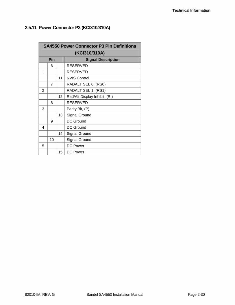
2.5.11 Power Connector P3 (KCI310/310A)
SA4550 Power Connector P3 Pin Definitions (KCI310/310A)
Pin Signal Description 6 RESERVED 1 RESERVED 11 NVIS Control 7 RADALT SEL 0, (RS0) 2 RADALT SEL 1, (RS1) 12 Rad/Alt Display Inhibit, (RI) 8 RESERVED 3 Parity Bit, (P) 13 Signal Ground 9 DC Ground 4 DC Ground 14 Signal Ground 10 Signal Ground 5 DC Power 15 DC Power
Technical Information
82010-IM, REV. G Sandel SA4550 Installation Manual Page 2-31
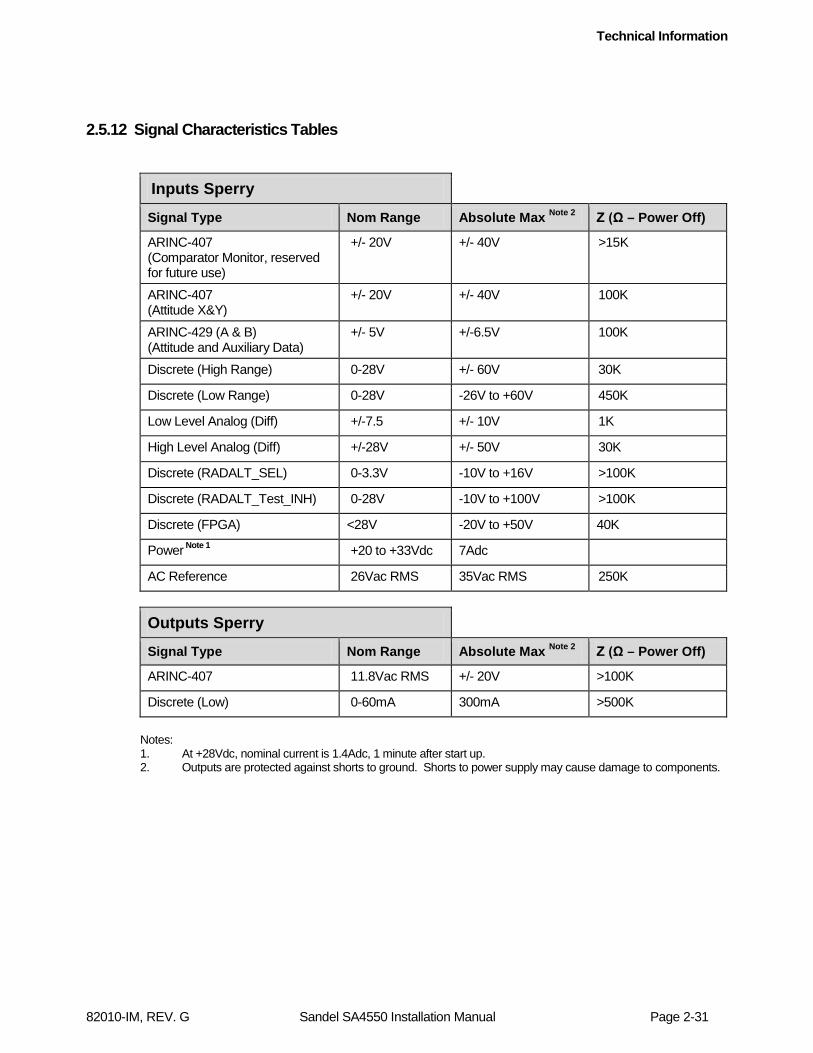
2.5.12 Signal Characteristics Tables
Inputs Sperry
Signal Type Nom Range Absolute Max Note 2 Z (Ω – Power Off)
ARINC-407 (Comparator Monitor, reserved for future use)
+/- 20V +/- 40V >15K
ARINC-407 (Attitude X&Y)
+/- 20V +/- 40V 100K
ARINC-429 (A & B) (Attitude and Auxiliary Data)
+/- 5V +/-6.5V 100K
Discrete (High Range) 0-28V +/- 60V 30K
Discrete (Low Range) 0-28V -26V to +60V 450K
Low Level Analog (Diff) +/-7.5 +/- 10V 1K
High Level Analog (Diff) +/-28V +/- 50V 30K
Discrete (RADALT_SEL) 0-3.3V -10V to +16V >100K
Discrete (RADALT_Test_INH) 0-28V -10V to +100V >100K
Discrete (FPGA) <28V -20V to +50V 40K
Power Note 1 +20 to +33Vdc 7Adc
AC Reference 26Vac RMS 35Vac RMS 250K
Outputs Sperry Signal Type Nom Range Absolute Max Note 2 Z (Ω – Power Off)
ARINC-407 11.8Vac RMS +/- 20V >100K
Discrete (Low) 0-60mA 300mA >500K
Notes: 1. At +28Vdc, nominal current is 1.4Adc, 1 minute after start up. 2. Outputs are protected against shorts to ground. Shorts to power supply may cause damage to components.

Technical Information
82010-IM, REV. G Sandel SA4550 Installation Manual Page 2-32
Inputs Collins Signal Type Nom Range Absolute Max Note 2 Z (Ω – Power Off)
ARINC-407 (Comparator Monitor, reserved for future use)
+/- 20V +/- 40V >15K
ARINC-407 (Attitude X&Y)
+/- 20V +/- 40V 100K
ARINC-429 (A & B) (Attitude and Auxiliary Data)
+/- 5V +/-6.5V 100K
Discrete (High Range) 0-28V +/- 60V 30K
Discrete (Low Range) 0-28V -26V to +60V 450K
Low Level Analog (Diff) +/-7.5 +/- 10V 1K
Diff Analog – ADI 84A FD +/-27V +/- 44V 20K
Diff Analog – ADI 84C FD Pitch +/-2.6V +/- 44V 6.7K
Diff Analog – ADI 84C FD Roll +/-4.3V +/- 44V 7.3K
High Level Analog (Diff) – Valid 0-28V +/- 60V 47.5K
High Level Analog (Diff) – Data +/-28V +/- 47V 22K
High Level Analog (Diff) – Speed Flag
0-33V +/- 60V 91.9K
Power Note 1 +20 to +33Vdc 7Adc
AC Reference 26Vac RMS 35Vac RMS 250K
Outputs Collins Signal Type Nom Range Absolute Max Note 2 Z (Ω – Power Off)
ARINC-407 11.8Vac RMS +/- 20V >100K
Discrete (Low) 0-60mA 300mA >500K
Notes: 1. At +28Vdc, nominal current is 1.4Adc, 1 minute after start up. 2. Outputs are protected against shorts to ground. Shorts to power supply may cause damage to components.
Technical Information
82010-IM, REV. G Sandel SA4550 Installation Manual Page 2-33
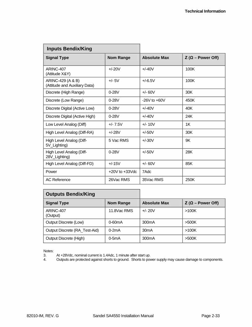
Inputs Bendix/King
Signal Type Nom Range Absolute Max Z (Ω – Power Off)
ARINC-407 (Attitude X&Y)
+/-20V +/-40V 100K
ARINC-429 (A & B) (Attitude and Auxiliary Data)
+/- 5V +/-6.5V 100K
Discrete (High Range) 0-28V +/- 60V 30K
Discrete (Low Range) 0-28V -26V to +60V 450K
Discrete Digital (Active Low) 0-28V +/-40V 40K
Discrete Digital (Active High) 0-28V +/-40V 24K
Low Level Analog (Diff) +/- 7.5V +/- 10V 1K
High Level Analog (Diff-RA) +/-28V +/-50V 30K
High Level Analog (Diff-5V_Lighting)
5 Vac RMS +/-30V 9K
High Level Analog (Diff-28V_Lighting)
0-28V +/-50V 28K
High Level Analog (Diff-FD) +/-15V +/- 60V 85K
Power +20V to +33Vdc 7Adc
AC Reference 26Vac RMS 35Vac RMS 250K
Outputs Bendix/King Signal Type Nom Range Absolute Max Z (Ω – Power Off)
ARINC-407 (Output)
11.8Vac RMS +/- 20V >100K
Output Discrete (Low) 0-60mA 300mA >500K
Output Discrete (RA_Test-Aid) 0-2mA 30mA >100K
Output Discrete (High) 0-5mA 300mA >500K
Notes: 3. At +28Vdc, nominal current is 1.4Adc, 1 minute after start up. 4. Outputs are protected against shorts to ground. Shorts to power supply may cause damage to components.
Technical Information
82010-IM, REV. G Sandel SA4550 Installation Manual Page 2-34
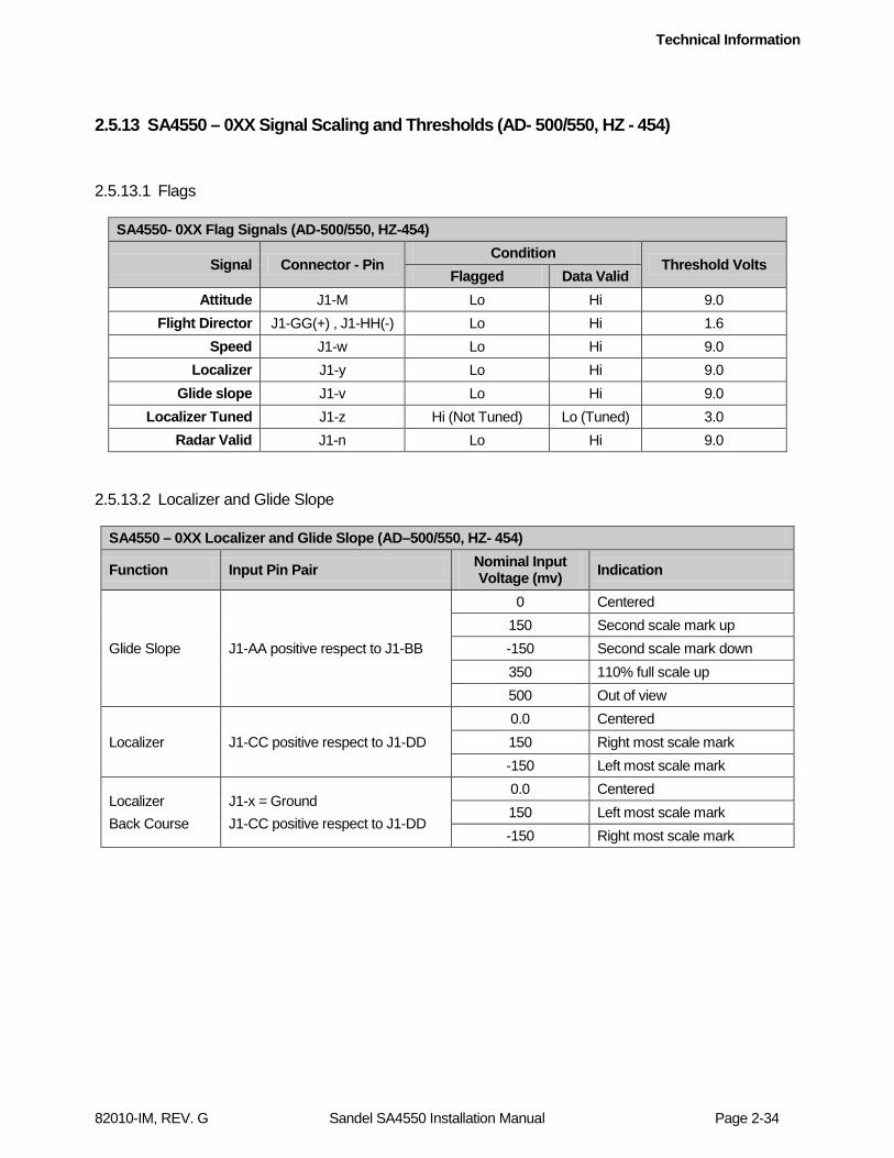
2.5.13 SA4550 – 0XX Signal Scaling and Thresholds (AD- 500/550, HZ - 454)
2.5.13.1 Flags
SA4550- 0XX Flag Signals (AD-500/550, HZ-454)
Signal Connector - Pin Condition
Threshold Volts Flagged Data Valid
Attitude J1-M Lo Hi 9.0 Flight Director J1-GG(+) , J1-HH(-) Lo Hi 1.6
Speed J1-w Lo Hi 9.0 Localizer J1-y Lo Hi 9.0
Glide slope J1-v Lo Hi 9.0 Localizer Tuned J1-z Hi (Not Tuned) Lo (Tuned) 3.0
Radar Valid J1-n Lo Hi 9.0
2.5.13.2 Localizer and Glide Slope
SA4550 – 0XX Localizer and Glide Slope (AD–500/550, HZ- 454)
Function Input Pin Pair Nominal Input Voltage (mv) Indication
Glide Slope J1-AA positive respect to J1-BB
0 Centered 150 Second scale mark up -150 Second scale mark down 350 110% full scale up 500 Out of view
Localizer J1-CC positive respect to J1-DD 0.0 Centered 150 Right most scale mark -150 Left most scale mark
Localizer Back Course
J1-x = Ground J1-CC positive respect to J1-DD
0.0 Centered 150 Left most scale mark -150 Right most scale mark

Technical Information
82010-IM, REV. G Sandel SA4550 Installation Manual Page 2-35
2.5.13.3 Flight Directors
SA4550 – 0XX Flight Director Single Cue (AD-500/550 and HZ-454) Sperry Part Numbers: 7000836-901, -902, -903, -904, 909, -910- -911, -912, -923, -924 7001182-901, -902, -903, -904, -909, -910, -911, -912 4002531-454, -901, -902, -903, -904, -905
Function Input Pin Pair Nominal Input Voltage (mv) Indication
FD Pitch Command
J1-p positive respect to J1-q
0.0 0 pitch command. 240 10 degree climb.
-240 10 degree dive.
1600 Out of view.
FD Roll Command
J1-s positive respect to J1-t
0.0 0 roll. 225 30 degrees right roll. -225 30 degrees left roll. -1600 Out of view
SA4550 – 0XX Flight Director Dual Cue (AD-500/550) Part Numbers: 7000836-905, -906, -913, -914, -921, -922 7001182-905, -906, -913, -914, -916, -917, -918, -919
Function Input Pin Pair Nominal Input Voltage (mv) Indication
FD Horizontal Command
J1-p positive respect to J1-q
0 Centered 235 10 degree climb. -235 10 degree dive. 1500 Out of view
FD Vertical Command
J1-s positive respect to J1-t
0 Centered 530 Full right command -530 Full left command -1500 Out of view
2.5.13.4 Speed Command Indicator
SA4550 – 0XX Speed Command (AD-550) Input Pin Pair Nominal Input Volts Indication
J1-S positive respect to J1-D 0 Centered
2.0 Second scale mark up -2.0 Second scale mark down
Technical Information
82010-IM, REV. G Sandel SA4550 Installation Manual Page 2-36
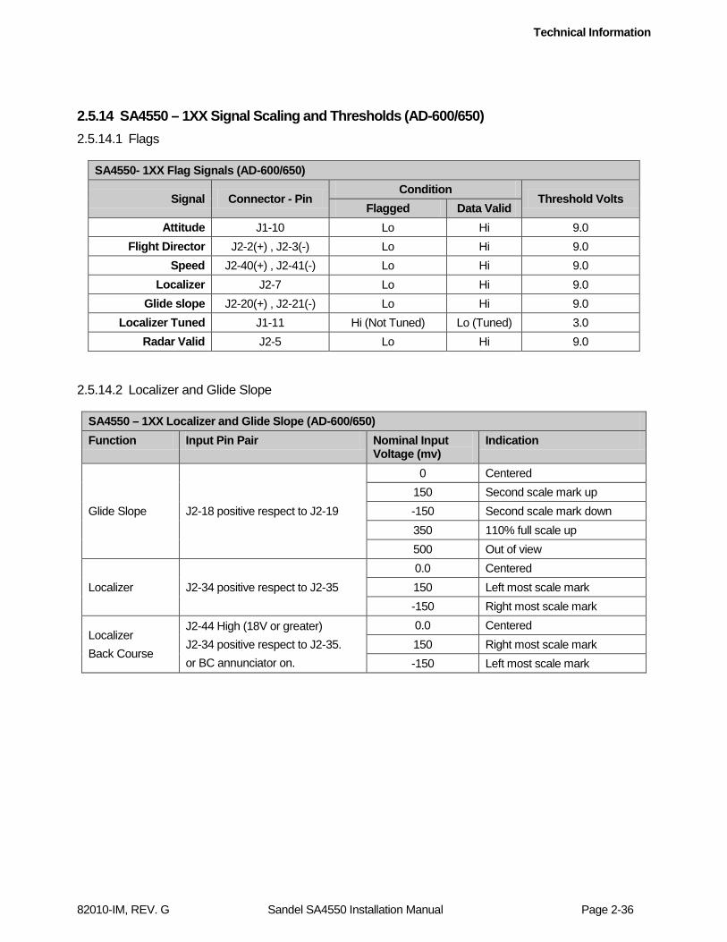
2.5.14 SA4550 – 1XX Signal Scaling and Thresholds (AD-600/650) 2.5.14.1 Flags
SA4550- 1XX Flag Signals (AD-600/650)
Signal Connector - Pin Condition
Threshold Volts Flagged Data Valid
Attitude J1-10 Lo Hi 9.0 Flight Director J2-2(+) , J2-3(-) Lo Hi 9.0
Speed J2-40(+) , J2-41(-) Lo Hi 9.0 Localizer J2-7 Lo Hi 9.0
Glide slope J2-20(+) , J2-21(-) Lo Hi 9.0 Localizer Tuned J1-11 Hi (Not Tuned) Lo (Tuned) 3.0
Radar Valid J2-5 Lo Hi 9.0
2.5.14.2 Localizer and Glide Slope
SA4550 – 1XX Localizer and Glide Slope (AD-600/650) Function Input Pin Pair Nominal Input
Voltage (mv) Indication
Glide Slope J2-18 positive respect to J2-19
0 Centered 150 Second scale mark up -150 Second scale mark down 350 110% full scale up 500 Out of view
Localizer J2-34 positive respect to J2-35 0.0 Centered 150 Left most scale mark -150 Right most scale mark
Localizer Back Course
J2-44 High (18V or greater) J2-34 positive respect to J2-35. or BC annunciator on.
0.0 Centered 150 Right most scale mark -150 Left most scale mark

Technical Information
82010-IM, REV. G Sandel SA4550 Installation Manual Page 2-37
2.5.14.3 Flight Directors
SA4550 – 1XX Flight Director Single Cue (AD-600/650) Sperry Part Numbers: 4020547-901, -904, -905, -906, -907, -908 7000466-901 thru -908, -916, -926, -936, -946, -951, -953, -955, -957, -966, -966, -986
Function Input Pin Pair Nominal Input Voltage (mv) Indication
FD Pitch Command
J2-23 positive respect to J2-24
0.0 mv 0 pitch command. 1.2 V 10 degree climb. -1.2 V 10 degree dive. 7.5 V Out of view.
FD Roll Command
J2-25 positive respect to J2-26
0.0 mv 0 roll. 900 mv 30 degrees right roll.
-900 mv 30 degrees left roll.
7.5 V Out of view
SA4550 – 1XX Flight Director Dual Cue (AD-600/650) Sperry Part Numbers: 7000466-909 thru -915, -920, -925, -925, -935, -945, -959, -961
Function Input Pin Pair Nominal Input Voltage (volts) Indication
FD Horizontal Command
J2-23 positive respect to J2-24
0 Centered 1.1 10 degree climb. -1.1 10 degree dive. 7.0 Out of view
FD Vertical Command
J2-25 positive respect to J2-26
0 Centered 2.5 Full right command -2.5 Full left command 7.0 Out of view
Technical Information
82010-IM, REV. G Sandel SA4550 Installation Manual Page 2-38
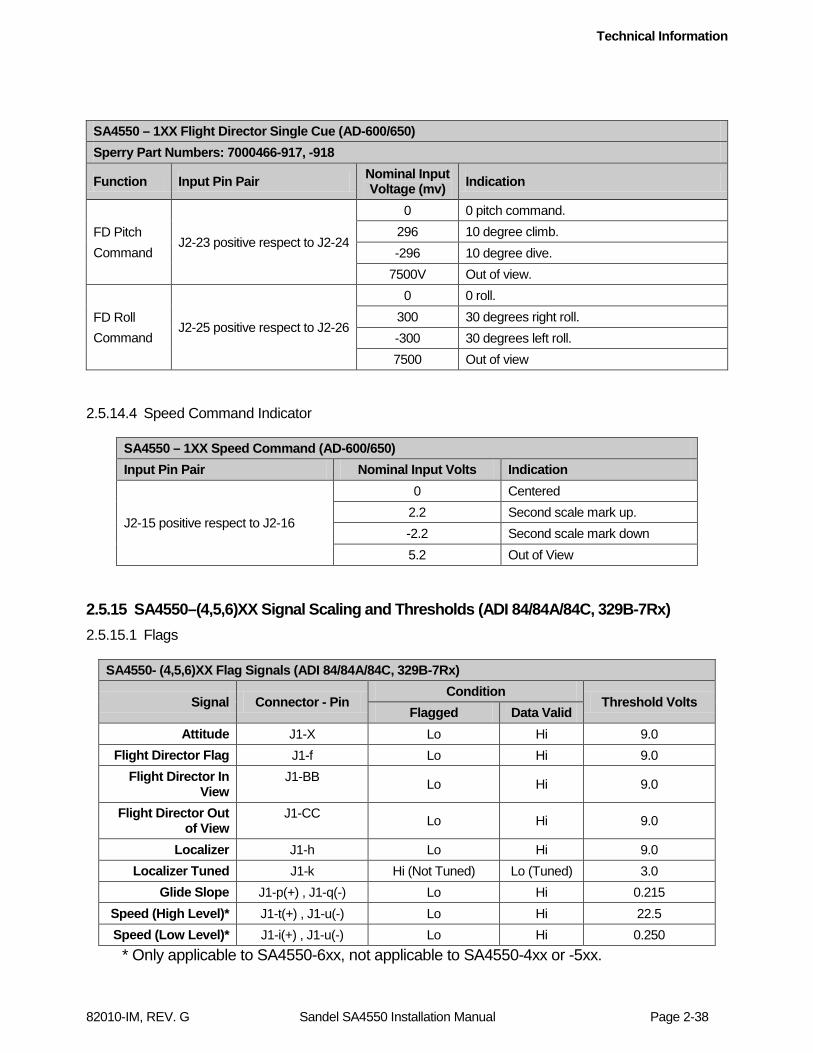
SA4550 – 1XX Flight Director Single Cue (AD-600/650) Sperry Part Numbers: 7000466-917, -918
Function Input Pin Pair Nominal Input Voltage (mv) Indication
FD Pitch Command
J2-23 positive respect to J2-24
0 0 pitch command. 296 10 degree climb. -296 10 degree dive.
7500V Out of view.
FD Roll Command
J2-25 positive respect to J2-26
0 0 roll. 300 30 degrees right roll. -300 30 degrees left roll. 7500 Out of view
2.5.14.4 Speed Command Indicator
SA4550 – 1XX Speed Command (AD-600/650) Input Pin Pair Nominal Input Volts Indication
J2-15 positive respect to J2-16
0 Centered 2.2 Second scale mark up. -2.2 Second scale mark down 5.2 Out of View
2.5.15 SA4550–(4,5,6)XX Signal Scaling and Thresholds (ADI 84/84A/84C, 329B-7Rx) 2.5.15.1 Flags
SA4550- (4,5,6)XX Flag Signals (ADI 84/84A/84C, 329B-7Rx)
Signal Connector - Pin Condition
Threshold Volts Flagged Data Valid
Attitude J1-X Lo Hi 9.0 Flight Director Flag J1-f Lo Hi 9.0
Flight Director In View
J1-BB Lo Hi 9.0
Flight Director Out of View
J1-CC Lo Hi 9.0
Localizer J1-h Lo Hi 9.0 Localizer Tuned J1-k Hi (Not Tuned) Lo (Tuned) 3.0
Glide Slope J1-p(+) , J1-q(-) Lo Hi 0.215 Speed (High Level)* J1-t(+) , J1-u(-) Lo Hi 22.5 Speed (Low Level)* J1-i(+) , J1-u(-) Lo Hi 0.250
* Only applicable to SA4550-6xx, not applicable to SA4550-4xx or -5xx.
Technical Information
82010-IM, REV. G Sandel SA4550 Installation Manual Page 2-39
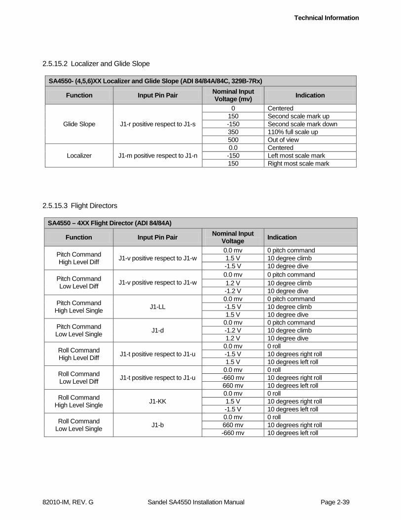
2.5.15.2 Localizer and Glide Slope
SA4550- (4,5,6)XX Localizer and Glide Slope (ADI 84/84A/84C, 329B-7Rx)
Function Input Pin Pair Nominal Input Voltage (mv) Indication
Glide Slope J1-r positive respect to J1-s
0 Centered 150 Second scale mark up -150 Second scale mark down 350 110% full scale up 500 Out of view
Localizer J1-m positive respect to J1-n 0.0 Centered
-150 Left most scale mark 150 Right most scale mark
2.5.15.3 Flight Directors
SA4550 – 4XX Flight Director (ADI 84/84A)
Function Input Pin Pair Nominal Input Voltage Indication
Pitch Command High Level Diff J1-v positive respect to J1-w
0.0 mv 0 pitch command 1.5 V 10 degree climb -1.5 V 10 degree dive
Pitch Command Low Level Diff J1-v positive respect to J1-w
0.0 mv 0 pitch command 1.2 V 10 degree climb -1.2 V 10 degree dive
Pitch Command High Level Single J1-LL
0.0 mv 0 pitch command -1.5 V 10 degree climb 1.5 V 10 degree dive
Pitch Command Low Level Single J1-d
0.0 mv 0 pitch command -1.2 V 10 degree climb 1.2 V 10 degree dive
Roll Command High Level Diff J1-t positive respect to J1-u
0.0 mv 0 roll -1.5 V 10 degrees right roll 1.5 V 10 degrees left roll
Roll Command Low Level Diff J1-t positive respect to J1-u
0.0 mv 0 roll -660 mv 10 degrees right roll 660 mv 10 degrees left roll
Roll Command High Level Single J1-KK
0.0 mv 0 roll 1.5 V 10 degrees right roll -1.5 V 10 degrees left roll
Roll Command Low Level Single J1-b
0.0 mv 0 roll 660 mv 10 degrees right roll -660 mv 10 degrees left roll
Technical Information
82010-IM, REV. G Sandel SA4550 Installation Manual Page 2-40
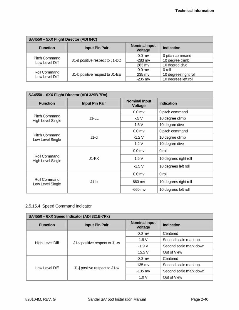
SA4550 – 5XX Flight Director (ADI 84C)
Function Input Pin Pair Nominal Input Voltage Indication
Pitch Command Low Level Diff J1-d positive respect to J1-DD
0.0 mv 0 pitch command -283 mv 10 degree climb 283 mv 10 degree dive
Roll Command Low Level Diff J1-b positive respect to J1-EE
0.0 mv 0 roll 235 mv 10 degrees right roll -235 mv 10 degrees left roll
SA4550 – 6XX Flight Director (ADI 329B-7Rx)
Function Input Pin Pair Nominal Input Voltage Indication
Pitch Command High Level Single J1-LL
0.0 mv 0 pitch command -.5 V 10 degree climb 1.5 V 10 degree dive
Pitch Command Low Level Single J1-d
0.0 mv 0 pitch command -1.2 V 10 degree climb 1.2 V 10 degree dive
Roll Command High Level Single J1-KK
0.0 mv 0 roll
1.5 V 10 degrees right roll
-1.5 V 10 degrees left roll
Roll Command Low Level Single J1-b
0.0 mv 0 roll
660 mv 10 degrees right roll
-660 mv 10 degrees left roll
2.5.15.4 Speed Command Indicator
SA4550 – 6XX Speed Indicator (ADI 321B-7Rx)
Function Input Pin Pair Nominal Input Voltage Indication
High Level Diff J1-v positive respect to J1-w
0.0 mv Centered 1.9 V Second scale mark up. -1.9 V Second scale mark down 15.5 V Out of View
Low Level Diff J1-j positive respect to J1-w
0.0 mv Centered 135 mv Second scale mark up. -135 mv Second scale mark down
1.0 V Out of View
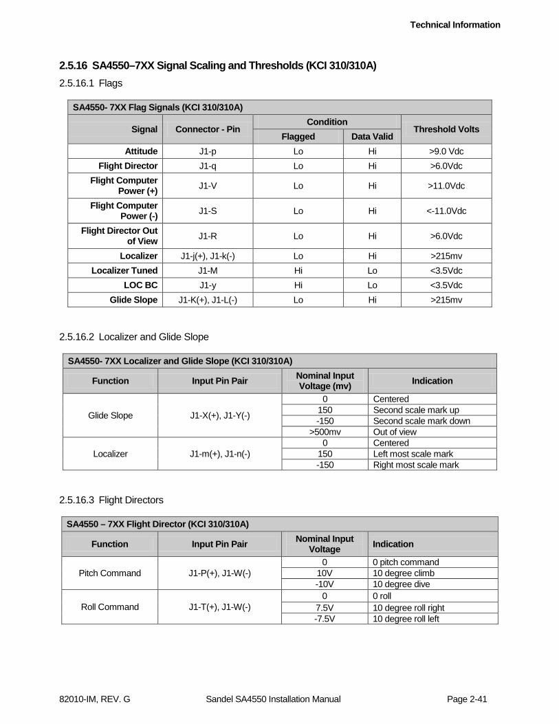
Technical Information
82010-IM, REV. G Sandel SA4550 Installation Manual Page 2-41
2.5.16 SA4550–7XX Signal Scaling and Thresholds (KCI 310/310A) 2.5.16.1 Flags
SA4550- 7XX Flag Signals (KCI 310/310A)
Signal Connector - Pin Condition
Threshold Volts Flagged Data Valid
Attitude J1-p Lo Hi >9.0 Vdc Flight Director J1-q Lo Hi >6.0Vdc
Flight Computer Power (+) J1-V Lo Hi >11.0Vdc
Flight Computer Power (-) J1-S Lo Hi <-11.0Vdc
Flight Director Out of View J1-R Lo Hi >6.0Vdc
Localizer J1-j(+), J1-k(-) Lo Hi >215mv Localizer Tuned J1-M Hi Lo <3.5Vdc
LOC BC J1-y Hi Lo <3.5Vdc Glide Slope J1-K(+), J1-L(-) Lo Hi >215mv
2.5.16.2 Localizer and Glide Slope
SA4550- 7XX Localizer and Glide Slope (KCI 310/310A)
Function Input Pin Pair Nominal Input Voltage (mv) Indication
Glide Slope J1-X(+), J1-Y(-)
0 Centered 150 Second scale mark up -150 Second scale mark down
>500mv Out of view
Localizer J1-m(+), J1-n(-) 0 Centered
150 Left most scale mark -150 Right most scale mark
2.5.16.3 Flight Directors
SA4550 – 7XX Flight Director (KCI 310/310A)
Function Input Pin Pair Nominal Input Voltage Indication
Pitch Command J1-P(+), J1-W(-) 0 0 pitch command
10V 10 degree climb -10V 10 degree dive
Roll Command J1-T(+), J1-W(-) 0 0 roll
7.5V 10 degree roll right -7.5V 10 degree roll left
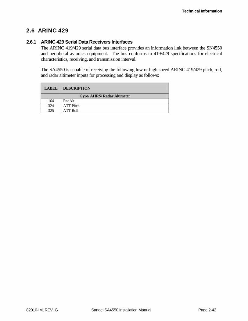
Technical Information
82010-IM, REV. G Sandel SA4550 Installation Manual Page 2-42
2.6 ARINC 429
2.6.1 ARINC 429 Serial Data Receivers Interfaces The ARINC 419/429 serial data bus interface provides an information link between the SN4550 and peripheral avionics equipment. The bus conforms to 419/429 specifications for electrical characteristics, receiving, and transmission interval.
The SA4550 is capable of receiving the following low or high speed ARINC 419/429 pitch, roll, and radar altimeter inputs for processing and display as follows:
LABEL DESCRIPTION
Gyro/ AHRS/ Radar Altimeter 164 RadAlt 324 ATT Pitch 325 ATT Roll

Installation
82010-IM, REV. G Sandel SA4550 Installation Manual Page 3-1
3 Installation
3.1 General
This section provides general suggestions and information to consider before installing the SA4550 including interconnect diagrams, mounting dimensions and information pertaining to installation. Close adherence to these suggestions will assure optimum performance.
3.1.1 Unpacking and Inspecting Equipment Exercise extreme care when unpacking the equipment. Make a visual inspection of the unit for evidence of damage incurred during shipment. If a claim for damage is to be made, save the shipping container to substantiate the claim. The claim should be promptly filed with the carrier. It would be advisable to retain the container and packaging material after all equipment has been removed in the event that equipment storage or reshipment should become necessary.
3.2 Installation Considerations
3.2.1 General Considerations The SA4550 should be installed in accordance with standards established by the customer’s installing agency, and existing conditions as to unit location and type of installation. However, the following considerations should be heeded before installing the SA4550. Close adherence to these considerations will assure a more satisfactory performance from the equipment. The installing agency will supply and fabricate all external cables. The required connectors and associated hardware are supplied by Sandel Avionics.
3.2.2 Cooling Considerations The SA4550 contains its own ventilation fan for internal component cooling and therefore, does not require a forced air cooling system. Any questions concerning cooling can be verified in the post-installation checkout by monitoring the SA4550 Internal temperature on the Power maintenance page.
3.2.3 Mechanical Installation Considerations The SA4550 installation should conform to customer requirements and airworthiness standards affecting the location and type of installation. §25.1321(a) stipulates that: “Each flight, navigation, and power plant instrument for use by any pilot must be plainly visible to him from his station with the minimum practicable deviation from his normal position and line of vision when he is looking forward along the flight path.”
§ 25.1321(b) stipulates: “The flight instruments required by §25.1303 must be grouped on the instrument panel and centered as nearly as practicable about the vertical plane of the pilot’s forward vision.” In addition - §25.1321(b)(4) states: “The instrument that most effectively indicates direction of flight must be adjacent to and directly below the

Installation
82010-IM, REV. G Sandel SA4550 Installation Manual Page 3-2
instrument in the top center position.” Similar regulations apply to Part 23 Small Airplanes.
Refer to Sandel Avionics, Drawing No. 82010-05 titled, “Layout, SA4550 Installation” for specific assembly and mounting instructions.
3.2.4 Electrical Installation Considerations The SA4550 has been designed environmentally tested to make use of the original aircraft wiring when replacing an electromechanical indicator listed in table 1-3.
All new wiring required by the installation must adhere to the following conditions. Connections and functions of the SA4550 are described in this section. Refer to the SA4550 Interconnect Wiring Diagrams for detailed wiring information and appropriate notes. Refer to the Connector Summary section for an explanation of pin functions.
A. The installing agency will supply and fabricate all wiring harnesses. The length and routing of wires must be carefully measured and planned before the actual installation is attempted. Avoid sharp bends in the harness or locating the harness near aircraft controls. Observe all recommended wire sizes and types and subscribe to appropriate FAR Parts 23, 25, 27, and 29, as well as AC 43.13-1( ) and -2( ).
B. The use of MIL-C-27500 shielded wire and MIL-W-22759 single conductor wire is recommended. The use of ferrules or grounding blocks for signal ground and digital ground returns is satisfactory; however, each ground return must be electrically separated.
C. In order to ensure optimum performance the SA4550 and associated wiring must be kept at least a minimum of three feet from high noise sources and not routed with cables from high power sources.
E. Prior to installing the SA4550, a point-to-point continuity check of the wiring harness should be accomplished to verify proper wiring. See functional ground test procedures in the appendix for verification of this step and other checks.
F. The Functional Pinout Descriptions on the following pages will assist you in determining installation requirements. Adhere to all notes within these descriptions and on installation wiring diagrams.
G. Ground Bonding. For new wiring ensure that two ground wires of at least the recommended size are installed in accordance with the installation drawings and these wires are connected to a bonded aircraft ground. Shielded wiring should be used for all new installation wiring.
I. Power Wiring. To assure that the SA4550 will operate properly down to its rated minimum input voltage of 20Vdc, ensure that two power wires of at least the recommended size are connected from the ADI circuit breaker to the SA4550 in accordance with the installation drawings.

Setup Procedures
82010-IM, REV. G Sandel SA4550 Installation Manual Page 4-1
4 Setup Procedures
4.1 General
Setup procedures for the SA4550 are described along with the Maintenance Menu below. The Maintenance Menu is accessed and addressed through the use of pushbuttons and the Selected Heading knob.
4.2 Accessing the Maintenance Menus
To access the Maintenance Menus perform the following operations:
A. Prior to applying power to the SA4550, press both the [M} button and the [ATT TEST] Button, then apply power to the unit. Continue to hold until the first maintenance menu appears. This protocol insures that maintenance menus cannot be called up accidentally during flight.
B. Once the Maintenance Menu is entered, rotate the rotary knob to cycle the through the page selections on the INDEX page. Press [M] to select desired page. On some menus additional soft key legends will appear as prompts. Pull the [MINS] knob out and rotate it to adjust any editable field.
C. Escape the maintenance menus by pressing and holding the [MINS] knob. This will allow normal operation of the unit to test the effects of settings. Re-enter the maintenance pages pressing and holding the [MINS] knob.
D. To disable maintenance menu operation, power down and restart normally. All configured items are stored in non-volatile memory.

Setup Procedures
82010-IM, REV. G Sandel SA4550 Installation Manual Page 4-2
4.3 Equipment/Configuration Selections
4.3.1 Radar Altimeter Configuration for Sperry Indicators Table 4-1A defines the supported Radar altimeters and rear connector configuration settings for SA4550 dash numbers replacing Sperry indicators.
Table 4-1A: Radar Altimeter Configuration1
Type* SA4550-0XX
J2-K SA4550-0XX
J2-L SA4550-1XX
J2-8 SA4550-1XX
J2-6 Sperry AA-215/236/300 or ARINC-429 Open Open Open Open
ARINC 552 Open Connect to J2-J Open Connect to
J2-1 Collins ALT-50 Connect to
J2-J Open Connect to J2-1 Open
Collins ALT-55 Connect to J2-J
Connect to J2-J
Connect to J2-1
Connect to J2-1
*For radar altimeters not listed, contact Sandel Avionics technical support to determine the appropriate rear connector configuration 1Sperry Indicators may be configured to utilize Bendix/King KRA-405/405B Radar Altimeters. See section 4.3.3 below for compatibility information.
4.3.2 Radar Altimeter Configuration for Collins Indicators Table 4-1B defines the supported Radar altimeters and rear connector configuration settings for SA4550 dash numbers replacing Collins indicators (ADI 84/84A/84C 329B-7Rx).
Table 4-1B: Radar Altimeter Configuration1
Type* P3-7 P3-2 P3-12
Sperry AA-215/236/300 or ARINC-429 Open Open Open
ARINC 552 Open Connect to P3-10 Open
Collins ALT-50 Connect to P3-13 Open Open
Collins ALT-55 Connect to P3-13
Connect to P3-10 Open
*For radar altimeters not listed, contact Sandel Avionics technical support to determine the appropriate rear connector configuration. 1Collins Indicators may be configured to utilize Bendix/King KRA-405/405B Radar Altimeters. See section 4.3.3 below for compatibility information.
4.3.3 Radar Altimeter Configuration for King KCI-310/310A Indicators Table 4-1C defines the supported Radar altimeters and rear connector configuration settings for SA4550 dash numbers replacing King KCI 310/310A indicators. Bendix/King KRA-405/405B radar altimeters may be used with the SA4550-7XX (KCI310/310A variant). When using auxiliary output 1 of the radar altimeter, use the rear

Setup Procedures
82010-IM, REV. G Sandel SA4550 Installation Manual Page 4-3
connector configuration for a Collins ALT-55. When using auxiliary output #2 of the radar altimeter (on -0101 models), use the rear connector configuration for a Sperry AA-215/236/300. When using auxiliary output #2 of the radar altimeter (on -0202 models), use the rear connector configuration for ARINC 552. The RADALT maintenance page will indicate the radar altimeter type of the rear connector configuration used. Note: The Bendix/King KRA-405B optionally provides an ARINC-429 output.
Table 4-1C: Radar Altimeter Configuration
Type* P3-7 P3-2 P3-12
Sperry AA-215/236/300 or ARINC-429 Open Open Open
ARINC 552 Open Connect to P3-10 Open
Collins ALT-50 Connect to P3-13 Open Open
Collins ALT-55 Connect to P3-13
Connect to P3-10 Open
* For radar altimeters not listed, contact Sandel Avionics technical support to determine the appropriate jumper configuration.
4.3.4 Sperry Indicators P3 Pin Configuration Strapping
Table 4-2 defines the supported functional replacement Sperry attitude indicators and their corresponding strapping configuration settings.
Table 4- 2: Connector P3 Pin Configuration Strapping
Model Part Number P SI RI AG1 AG0 SS1 SS0
P3-3 P3-8 P3-12 P3-2 P3-7 P3-1 P3-6
AD-500A 7000836-901, -902, -909, -910, -923, -924
OPEN GND GND OPEN OPEN OPEN OPEN
AD-500B 7000836-903, -904, -911, -912
OPEN GND GND OPEN OPEN OPEN OPEN
AD-500C 7000836-905, -906, -913, -914, -921, -922
GND GND GND OPEN OPEN OPEN GND
AD-550A 7001182-901, -902 GND GND OPEN OPEN OPEN OPEN OPEN
7001182-909, -910 OPEN OPEN OPEN OPEN OPEN OPEN OPEN
AD-550B 7001182-903, -904 GND GND OPEN OPEN OPEN OPEN OPEN
7001182-911, -912 OPEN OPEN OPEN OPEN OPEN OPEN OPEN
AD-550C 7001182-905, -906 OPEN GND OPEN OPEN OPEN OPEN GND
7001182-913, -914, -916, -917, -918, -919
GND OPEN OPEN OPEN OPEN OPEN GND
AD-600 4020547-901, -904 OPEN OPEN GND OPEN GND OPEN OPEN
AD-600A 7000466-903, -904, -953 OPEN OPEN GND OPEN GND OPEN OPEN
4020547-906, -907 OPEN OPEN GND OPEN GND OPEN OPEN
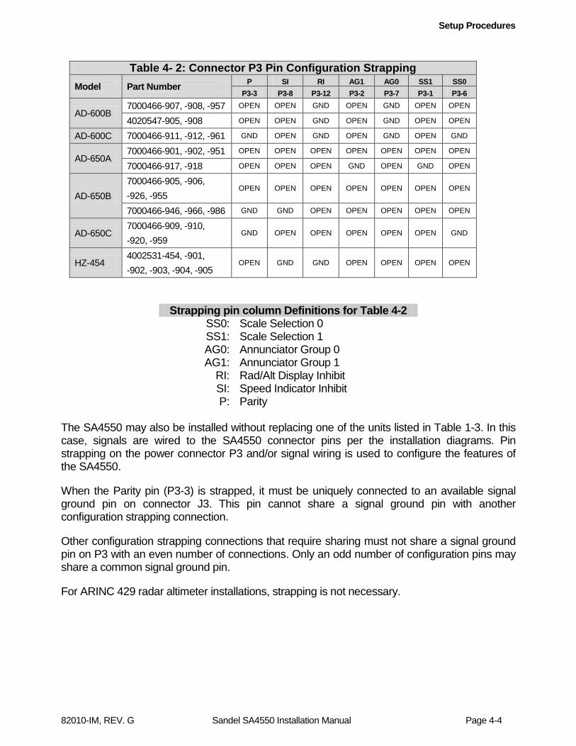
Setup Procedures
82010-IM, REV. G Sandel SA4550 Installation Manual Page 4-4
Table 4- 2: Connector P3 Pin Configuration Strapping
Model Part Number P SI RI AG1 AG0 SS1 SS0
P3-3 P3-8 P3-12 P3-2 P3-7 P3-1 P3-6
AD-600B 7000466-907, -908, -957 OPEN OPEN GND OPEN GND OPEN OPEN
4020547-905, -908 OPEN OPEN GND OPEN GND OPEN OPEN
AD-600C 7000466-911, -912, -961 GND OPEN GND OPEN GND OPEN GND
AD-650A 7000466-901, -902, -951 OPEN OPEN OPEN OPEN OPEN OPEN OPEN
7000466-917, -918 OPEN OPEN OPEN GND OPEN GND OPEN
AD-650B 7000466-905, -906, -926, -955
OPEN OPEN OPEN OPEN OPEN OPEN OPEN
7000466-946, -966, -986 GND GND OPEN OPEN OPEN OPEN OPEN
AD-650C 7000466-909, -910, -920, -959
GND OPEN OPEN OPEN OPEN OPEN GND
HZ-454 4002531-454, -901, -902, -903, -904, -905
OPEN GND GND OPEN OPEN OPEN OPEN
Strapping pin column Definitions for Table 4-2 SS0: Scale Selection 0 SS1: Scale Selection 1 AG0: Annunciator Group 0 AG1: Annunciator Group 1
RI: Rad/Alt Display Inhibit SI: Speed Indicator Inhibit P: Parity
The SA4550 may also be installed without replacing one of the units listed in Table 1-3. In this case, signals are wired to the SA4550 connector pins per the installation diagrams. Pin strapping on the power connector P3 and/or signal wiring is used to configure the features of the SA4550.
When the Parity pin (P3-3) is strapped, it must be uniquely connected to an available signal ground pin on connector J3. This pin cannot share a signal ground pin with another configuration strapping connection.
Other configuration strapping connections that require sharing must not share a signal ground pin on P3 with an even number of connections. Only an odd number of configuration pins may share a common signal ground pin.
For ARINC 429 radar altimeter installations, strapping is not necessary.

Operating Details
82010-IM, REV. G Sandel SA4550 Installation Manual Page 5-1
5 Operating Details
For an explanation of the operating controls of the SA4550, reference Sandel document 82010-PG, “SA4550 Primary Attitude Display Pilots Guide”.
Instructions for Continued Airworthiness
82010-IM, REV. G Sandel SA4550 Installation Manual Page 6-1
6 Instructions for Continued Airworthiness
Reference Sandel document ST12361LA-T-05, “SA4550 Primary Attitude Display Instructions for Continued Airworthiness”.
General Information
82010-IM, REV. G Sandel SA4550 Installation Manual Page 7-1
7 Appendix A: Post-Installation Procedures
After all wiring has been verified and the SA4550 has been installed into the panel, the maintenance pages may be accessed for calibration of the pitch attitude, slip/skid ball centering and RAD/ALT display. Prior to applying power to the SA4550, depress and hold the [M] button and [ATT TEST] buttons, and then apply power to the unit. Continue to press the buttons until the first maintenance menu appears. This protocol insures than maintenance menus cannot be called up accidentally during flight. If a calibration is required, momentarily press the [MINS] button to enter the edit mode.
Once the Maintenance Menu is entered, rotate the rotary knob to move the cursor to the desired maintenance page and press the SELECT soft key to enter the selected page. Rotate the knob to move the cursor up and down the maintenance page.
Escape the maintenance menus by pressing and holding the [MINS] knob. This will allow normal operation of the unit to test the effects of any changes made. Re-enter the maintenance pages by pressing and holding the [MINS] knob.
To disable maintenance menu operation, power down and restart normally. All calibration values will be stored in non-volatile memory.

General Information
82010-IM, REV. G Sandel SA4550 Installation Manual Page 7-2
7.1 Page 1: INDEX – All Models
Applicable to all models
The Maintenance Index page is a multiple-choice list that provides an index of all other maintenance pages and allows the operator to jump to a particular page. First scroll the Cursor to point to the desired maintenance page listing using the rotary knob. The [SELECT] Soft key is then pressed to jump to this page. Once in the maintenance pages, press the [M] button to return to the Maintenance Index page.
Momentarily pushing the [MODE] soft key (the [MINS] knob) enables the installer to toggle the SA4550 between READ and EDIT mode. Note: The SA4550 must be in EDIT mode to make calibration adjustments on the INSTALLATION or RADALT/DISC maintenance pages.

General Information
82010-IM, REV. G Sandel SA4550 Installation Manual Page 7-3
7.2 Page 2: INSTALLATION – Sperry Models
Applicable to Sperry Models: AD550/AD650
The INSTALLATION page provides configuration fields to adjust the pitch, slip/skid displays to correct for equipment installation errors and the ability to enable optional ARINC-429 Attitude and Auxiliary inputs.
Configuration Field Options Comment PTCH CAL Adjustable from +3.00° to -3.00°
PTCH Displays current aircraft pitch angle BALL CAL Adjustable from +5.0°to -5.0° FD STYLE SINGLE ONLY
DUAL ONLY SINGLE/DUAL
For single cue display only For dual cue display only For pilot selectable single cue / dual cue display
A429 KEY Enter purchased 11 – char activation key for A429 ATT/RA functionality.
ATT SRC XYZ 429 429H
Set to XYZ for Synchro XYZ attitude inputs. Set to 429 or 429H to receive ARINC-429 Pitch and Roll data on input pins Pitch X & Y.
AUX 429 NONE 429 429H
AUX 429 (Radar Alt) input mode is only available if ATT SRC = 429 or 429H.
DATA NONE RA
Selection not available if AUX 429 is set to NONE.
Rear Board Sperry AD550 or Sperry AD650
Master Scale Determined by strapping configuration
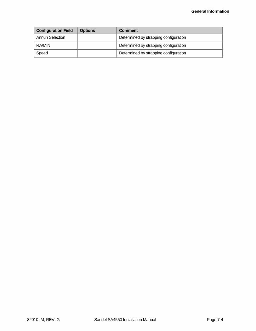
General Information
82010-IM, REV. G Sandel SA4550 Installation Manual Page 7-4
Configuration Field Options Comment Annun Selection Determined by strapping configuration
RA/MIN Determined by strapping configuration
Speed Determined by strapping configuration

General Information
82010-IM, REV. G Sandel SA4550 Installation Manual Page 7-5
7.3 Page 2: INSTALLATION – Collins Models
Applicable to Collins Models: 329B-7R, 7R-1, 2,3,4,5 / ADI84 / ADI84A / ADI84C
The INSTALLATION page provides configuration fields to adjust the pitch, slip/skid displays to correct for equipment installation errors and the ability to enable optional ARINC-429 Attitude and Auxiliary inputs.
Configuration Field Options Comment PTCH CAL Adjustable from +3.00° to -3.00°
PTCH Displays current aircraft pitch angle BALL CAL Adjustable from +5.0°to -5.0° FD STYLE SINGLE ONLY
DUAL ONLY SINGLE/DUAL
For single cue display only For dual cue display only For pilot selectable single cue / dual cue display
A429 KEY Enter purchased 11 – char activation key for A429 ATT/RA functionality.
ATT SRC XYZ 429 429H
Set to XYZ for Synchro XYZ attitude inputs. Set to 429 or 429H to receive ARINC-429 Pitch and Roll data on input pins Pitch X & Y.
AUX 429 NONE 429 429H
AUX 429 (Radar Alt) input mode is only available if ATT SRC = 429 or 429H.
DATA NONE RA
Selection not shown if AUX 429 is set to NONE.
Rear Board Collins 84
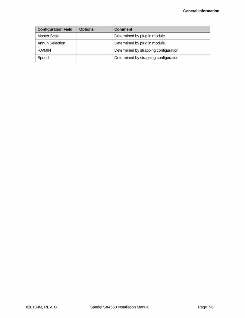
General Information
82010-IM, REV. G Sandel SA4550 Installation Manual Page 7-6
Configuration Field Options Comment Master Scale Determined by plug in module.
Annun Selection Determined by plug in module.
RA/MIN Determined by strapping configuration
Speed Determined by strapping configuration

General Information
82010-IM, REV. G Sandel SA4550 Installation Manual Page 7-7
7.4 Page 2: INSTALLATION – Bendix/King Models
Applicable to Bendix / King Models: KCI 310/310A
The INSTALLATION page provides configuration fields to adjust the pitch, slip/skid displays to correct for equipment installation errors and the ability to enable optional ARINC-429 Attitude and Auxiliary inputs..
Configuration Field Options Comment PTCH CAL Adjustable from +3.00° to -3.00°
PTCH Displays current aircraft pitch angle BALL CAL Adjustable from +5.0°to -5.0° FD STYLE SINGLE ONLY
DUAL ONLY SINGLE/DUAL
For single cue display only For dual cue display only For pilot selectable single cue / dual cue display
A429 KEY Enter purchased 11 – char activation key for A429 ATT/RA functionality.
ATT SRC XYZ 429 429H
Set to XYZ for Synchro XYZ attitude inputs. Set to 429 or 429H to receive ARINC-429 Pitch and Roll data on input pins Pitch X & Y.
AUX 429 NONE 429 429H
AUX 429 (Radar Alt) input mode is only available if ATT SRC = 429 or 429H.
DATA NONE RA
Selection not shown if AUX 429 is set to NONE.
Rear Board King KCI310
RA/MIN Determined by strapping configuration

General Information
82010-IM, REV. G Sandel SA4550 Installation Manual Page 7-8
7.5 Page 3: SUMMARY – Sperry and Collins Models
Applicable to Sperry and Collins models
The SUMMARY page provides a means to quickly check the status of all sensors interfaced to the SA4550. Page is for informational use only. There are no editable fields. Use the rotary knob to move the cursor next to the specific item to be selected. The value will be displayed at the top of the screen on the value line. The line below the value line is used to indicate whether the data is valid, timed out or in error. If line is displayed green, the data is valid, yellow text indicates the data is non-valid, timed out or in error.
Function Sensor AC PTCH Vertical Gyro – Aircraft Pitch
AC ROLL Vertical Gyro – Aircraft Roll
FD PTCH Flight Director Computer – Flight Director Pitch
FD ROLL Flight Director Computer – Flight Director Roll
FST/SLO Angle of Attack Sensor – Fast/Slow Indications
ENRGZ NAV Receiver – ILS Energize
LOC DV NAV Receiver – Localizer Deviation
GS DV NAV Receiver - Glideslope Deviation
RADALT Radar Altimeter – Radar Altitude

General Information
82010-IM, REV. G Sandel SA4550 Installation Manual Page 7-9
7.6 Page 3: SUMMARY – Bendix/King Models
Applicable to Bendix/King models
The SUMMARY page provides a means to quickly check the status of all sensors interfaced to the SA4550. Page is for informational use only. There are no editable fields. Use the rotary knob to move the cursor next to the specific item to be selected. The value will be displayed at the top of the screen on the value line. The line below the value line is used to indicate whether the data is valid, timed out or in error. If line is displayed green, the data is valid, yellow text indicates the data is non-valid, timed out or in error.
Function Sensor AC PTCH Vertical Gyro – Aircraft Pitch
AC ROLL Vertical Gyro – Aircraft Roll
FD PTCH Flight Director Computer – Flight Director Pitch
FD ROLL Flight Director Computer – Flight Director Roll
ENRGZ NAV Receiver – ILS Energize
LOC DV NAV Receiver – Localizer Deviation
GS DV NAV Receiver - Glideslope Deviation
RADALT Radar Altimeter – Radar Altitude
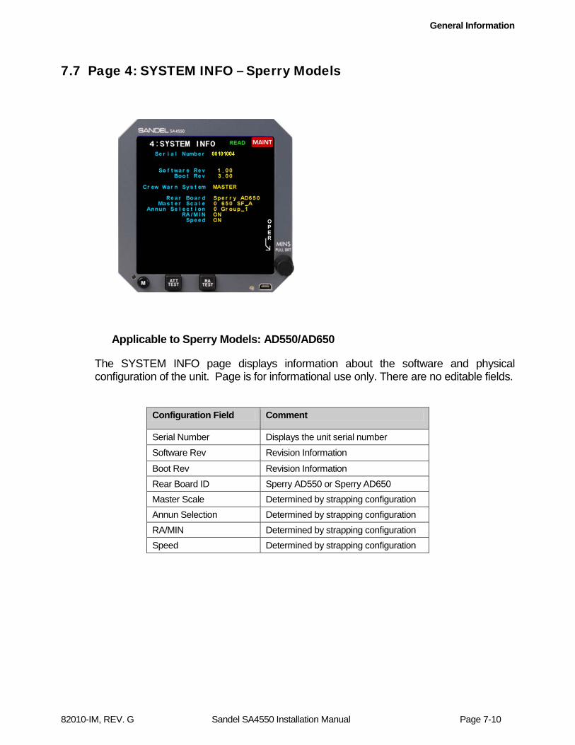
General Information
82010-IM, REV. G Sandel SA4550 Installation Manual Page 7-10
7.7 Page 4: SYSTEM INFO – Sperry Models
Applicable to Sperry Models: AD550/AD650
The SYSTEM INFO page displays information about the software and physical configuration of the unit. Page is for informational use only. There are no editable fields.
Configuration Field Comment
Serial Number Displays the unit serial number Software Rev Revision Information
Boot Rev Revision Information Rear Board ID Sperry AD550 or Sperry AD650 Master Scale Determined by strapping configuration Annun Selection Determined by strapping configuration RA/MIN Determined by strapping configuration Speed Determined by strapping configuration
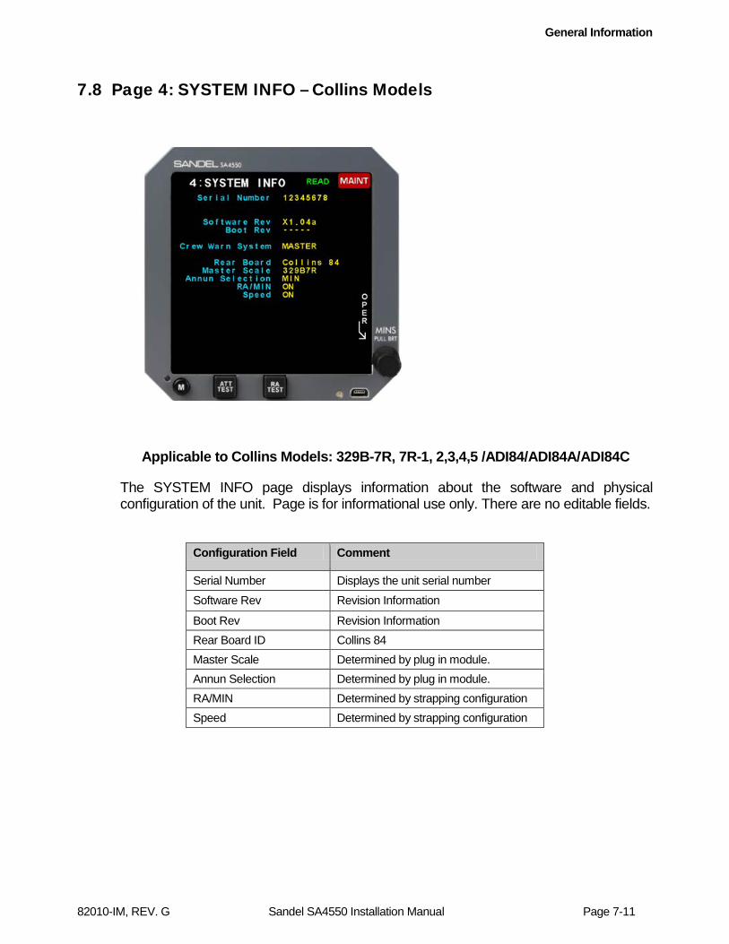
General Information
82010-IM, REV. G Sandel SA4550 Installation Manual Page 7-11
7.8 Page 4: SYSTEM INFO – Collins Models
Applicable to Collins Models: 329B-7R, 7R-1, 2,3,4,5 /ADI84/ADI84A/ADI84C
The SYSTEM INFO page displays information about the software and physical configuration of the unit. Page is for informational use only. There are no editable fields.
Configuration Field Comment
Serial Number Displays the unit serial number Software Rev Revision Information
Boot Rev Revision Information Rear Board ID Collins 84 Master Scale Determined by plug in module. Annun Selection Determined by plug in module. RA/MIN Determined by strapping configuration Speed Determined by strapping configuration

General Information
82010-IM, REV. G Sandel SA4550 Installation Manual Page 7-12
7.9 Page 4: SYSTEM INFO – Bendix/King Models
Applicable to Bendix/King Models: KCI 310/310A
The SYSTEM INFO page displays information about the software and physical configuration of the unit. Page is for informational use only. There are no editable fields.
Configuration Field Comment
Serial Number Displays the unit serial number Software Rev Revision Information
Boot Rev Revision Information Rear Board ID KCI310 RA/MIN Determined by strapping configuration

General Information
82010-IM, REV. G Sandel SA4550 Installation Manual Page 7-13
7.10 Page 5: ATT/FD – Sperry Models
Applicable to Sperry Models: AD550/AD650
The ATT/FD page displays information about the Attitude and Flight Director input signals. Page is for informational use only. There are no editable fields.
Configuration Field Comment
AC ROLL XYZ or A429 (Indicates Aircraft Roll). A429 input mode is enabled on the Installation Page
AC PITCH XYZ or A429 (Indicates Aircraft Pitch)
VALID HIGH or A429 (Indicates ATT valid status source)
FD ROLL 550 SF_A or 650 SF_A (A,B, or C depending on strapping configuration)
FD PTCH 550 SF_A or 650 SF_A (A,B, or C depending on strapping configuration)
VALID HIGH (Indicates FD valid status)
FST/SLO 550 FS or 650 FS (depending on strapping configuration)
VALID HIGH (Indicates Fast/Slow valid status)
ATT TEST
ACTIVE L (Indicates status of ATT TEST Inhibit)
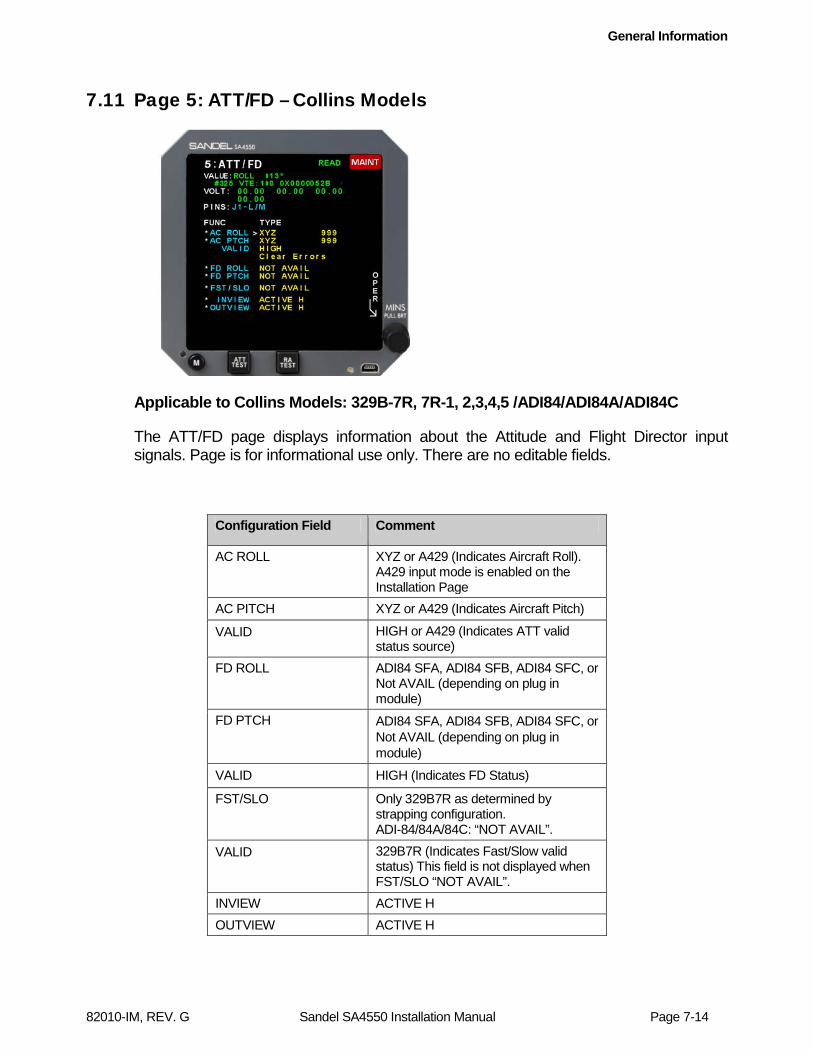
General Information
82010-IM, REV. G Sandel SA4550 Installation Manual Page 7-14
7.11 Page 5: ATT/FD – Collins Models
Applicable to Collins Models: 329B-7R, 7R-1, 2,3,4,5 /ADI84/ADI84A/ADI84C
The ATT/FD page displays information about the Attitude and Flight Director input signals. Page is for informational use only. There are no editable fields.
Configuration Field Comment
AC ROLL XYZ or A429 (Indicates Aircraft Roll). A429 input mode is enabled on the Installation Page
AC PITCH XYZ or A429 (Indicates Aircraft Pitch)
VALID HIGH or A429 (Indicates ATT valid status source)
FD ROLL ADI84 SFA, ADI84 SFB, ADI84 SFC, or Not AVAIL (depending on plug in module)
FD PTCH ADI84 SFA, ADI84 SFB, ADI84 SFC, or Not AVAIL (depending on plug in module)
VALID HIGH (Indicates FD Status)
FST/SLO Only 329B7R as determined by strapping configuration. ADI-84/84A/84C: “NOT AVAIL”.
VALID 329B7R (Indicates Fast/Slow valid status) This field is not displayed when FST/SLO “NOT AVAIL”.
INVIEW ACTIVE H OUTVIEW ACTIVE H

General Information
82010-IM, REV. G Sandel SA4550 Installation Manual Page 7-15
7.12 Page 5: ATT/FD – Bendix/King Models
Applicable to Bendix/King Models: KCI-310/KCI-310-A
The ATT/FD page displays information about the Attitude and Flight Director input signals. Page is for informational use only. There are no editable fields.
Configuration Field Comment
AC ROLL XYZ or A429 (Indicates Aircraft Roll). A429 input mode is enabled on the Installation Page
AC PITCH XYZ or A429 (Indicates Aircraft Pitch)
VALID HIGH or A429 (Indicates ATT valid status source)
FD ROLL KCI-310/KCI-310A
FD PTCH KCI-310
VALID ACTIVE H (Indicates FD Status)
21V- ACTIVE L
21V+ ACTIVE H
OUTVIEW ACTIVE L
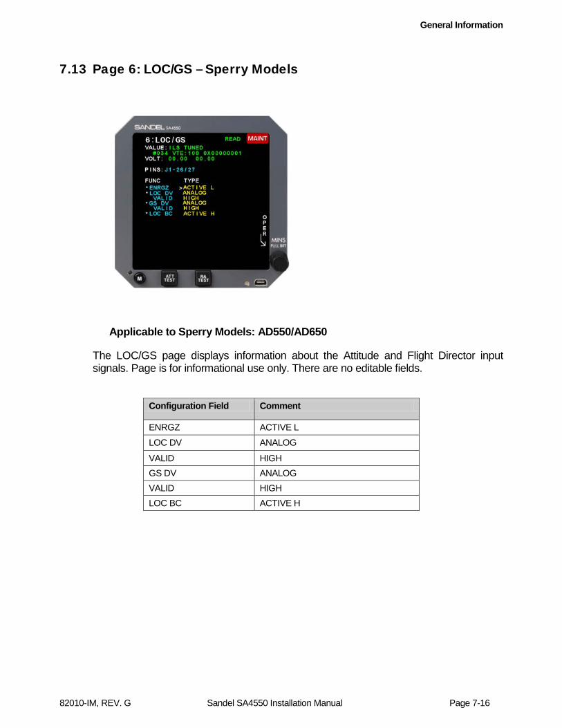
General Information
82010-IM, REV. G Sandel SA4550 Installation Manual Page 7-16
7.13 Page 6: LOC/GS – Sperry Models
Applicable to Sperry Models: AD550/AD650
The LOC/GS page displays information about the Attitude and Flight Director input signals. Page is for informational use only. There are no editable fields.
Configuration Field Comment
ENRGZ ACTIVE L LOC DV ANALOG
VALID HIGH GS DV ANALOG VALID HIGH LOC BC ACTIVE H

General Information
82010-IM, REV. G Sandel SA4550 Installation Manual Page 7-17
7.14 Page 6: LOC/GS – Collins Models
Applicable to Collins Models: 329B-7R, 7R-1, 2,3,4,5 /ADI84/ADI84A/ADI84C
The LOC/GS page displays information about the Attitude and Flight Director input signals. Page is for informational use only. There are no editable fields.
Configuration Field Comment
ENRGZ ACTIVE L LOC DV ANALOG
VALID HIGH GS DV ANALOG VALID LOWLEVEL

General Information
82010-IM, REV. G Sandel SA4550 Installation Manual Page 7-18
7.15 Page 6: LOC/GS – Bendix/King Models
Applicable to Bendix/King Models: KCI-310/KCI-310A
The LOC/GS page displays information about the Attitude and Flight Director input signals. Page is for informational use only. There are no editable fields.
Configuration Field Comment
ENRGZ ACTIVE L LOC DV ANALOG
VALID LOWLEVEL GS DV ANALOG VALID LOWLEVEL
LOC BC ACTIVE L

General Information
82010-IM, REV. G Sandel SA4550 Installation Manual Page 7-19
7.16 Page 7: RADALT – Sperry Models
Applicable to Sperry Models: AD550/AD650
Displays information associated with radar altimeter installation. This page allows for calibration of radar altimeter display. Configuration Field Comment
RALT
Shows the model of radar altimeter installed. (Determined by strapping configuration). Non-editable field. “NOT AVAILABLE” when radar altimeter not configured. “A429” when AUX ARINC-429 RA input is enabled on the Installation Page. See table 4-1A for a list of supported radar altimeters.
VALID HIGH or A429. Not shown when no radar altimeter configured.
CAL Displays below the RALT function when radar altimeter is installed. Adjustable from +25.0 to -25.0 feet. Does not display when RALT “NOT AVAILABLE”
RA TST “NONE” or “AVAILABLE”
BUTTON “ENABLE” or “DISABLE” (when configured as available).

General Information
82010-IM, REV. G Sandel SA4550 Installation Manual Page 7-20
7.17 Page 7: RADALT – Collins Models
Applicable to Collins Models: 329B-7R, 7R-1, 2,3,4,5 /ADI84/ADI84A/ADI84C
Displays information associated with radar altimeter installation. This page allows for calibration of radar altimeter display. Configuration Field Comment
RALT
Shows the model of radar altimeter installed. (Determined by strapping configuration). Non-editable field. “NOT AVAILABLE” when radar altimeter not configured. “A429” when AUX ARINC-429 RA input is enabled on the Installation Page. See table 4-1B for a list of supported radar altimeters.
VALID HIGH or A429. Not shown when no radar altimeter configured.
CAL Displays below the RALT function when radar altimeter is installed. Adjustable from +25.0 to -25.0 feet. Does not display when RALT “NOT AVAILABLE”
RA TST NONE

General Information
82010-IM, REV. G Sandel SA4550 Installation Manual Page 7-21
7.18 Page 7: RADALT – Bendix/King Models
Applicable to Bendix/King Models: KCI-310/KCI-310A
Displays information associated with radar altimeter installation. This page allows for calibration of radar altimeter display.
Configuration Field Comment
RALT
Shows the model of radar altimeter installed. (Determined by strapping configuration). Non-editable field. “NOT AVAILABLE” when radar altimeter not configured. “A429” when AUX ARINC-429 RA input is enabled on the Installation Page See table 4-1C for a list of supported radar altimeters.
VALID HIGH or A429. Not shown when no radar altimeter configured.
CAL Displays below the RALT function when radar altimeter is installed. Adjustable from +25.0 to -25.0 feet. Does not display when RALT “NOT AVAILABLE”
RA TST NONE or AVAILABLE
BUTTON “ENABLE” or “DISABLE” (when configured as available).
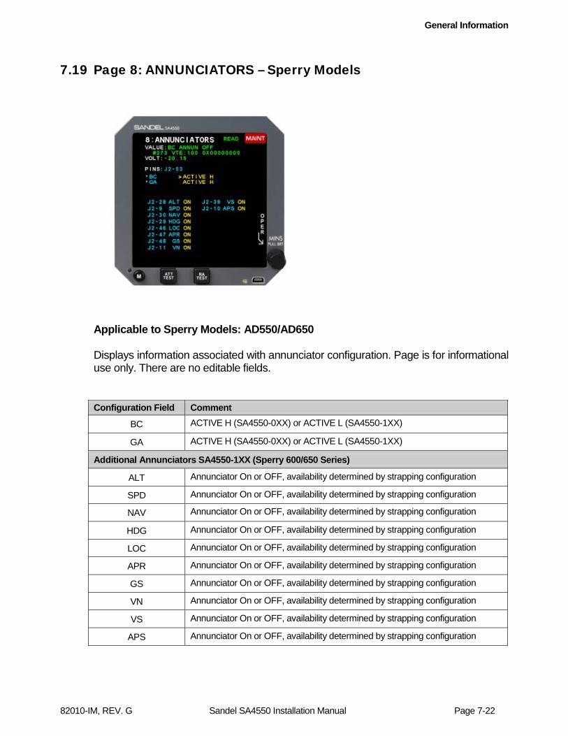
General Information
82010-IM, REV. G Sandel SA4550 Installation Manual Page 7-22
7.19 Page 8: ANNUNCIATORS – Sperry Models
Applicable to Sperry Models: AD550/AD650 Displays information associated with annunciator configuration. Page is for informational use only. There are no editable fields. Configuration Field Comment
BC ACTIVE H (SA4550-0XX) or ACTIVE L (SA4550-1XX)
GA ACTIVE H (SA4550-0XX) or ACTIVE L (SA4550-1XX)
Additional Annunciators SA4550-1XX (Sperry 600/650 Series)
ALT Annunciator On or OFF, availability determined by strapping configuration
SPD Annunciator On or OFF, availability determined by strapping configuration
NAV Annunciator On or OFF, availability determined by strapping configuration
HDG Annunciator On or OFF, availability determined by strapping configuration
LOC Annunciator On or OFF, availability determined by strapping configuration
APR Annunciator On or OFF, availability determined by strapping configuration
GS Annunciator On or OFF, availability determined by strapping configuration
VN Annunciator On or OFF, availability determined by strapping configuration
VS Annunciator On or OFF, availability determined by strapping configuration
APS Annunciator On or OFF, availability determined by strapping configuration

General Information
82010-IM, REV. G Sandel SA4550 Installation Manual Page 7-23
7.20 Page 8: ANNUNCIATORS – Collins Models
Applicable to Collins Models: 329B-7R, 7R-1, 2,3,4,5 /ADI84/ADI84A/ADI84C
Displays information associated with annunciator configuration. Page is for informational use only. There are no editable fields.
Configuration Field Comment
GA or MIN Determined by plug in module.

General Information
82010-IM, REV. G Sandel SA4550 Installation Manual Page 7-24
7.21 Page 8: ANNUNCIATORS – Bendix/King Models
Applicable to Bendix/King Models: KCI-310/KCI-310A
Displays information associated with annunciator configuration. Page is for informational use only. There are no editable fields.
Configuration Field Comment MDA ACTIVE L RNAV ACTIVE L MINS ACTIVE L

General Information
82010-IM, REV. G Sandel SA4550 Installation Manual Page 7-25
7.22 Page 9: BACKLIGHT – All Models
Applicable to Sperry, Collins, and Bendix/King models
Displays information associated with display colors and brightness. Page is for informational use only. There are no editable fields. Configuration Field Comment BACKLIGHT
Led Current Red Temp Grn Temp Blu Temp SwTemp
LED current draw RED LED Temperature Green LED Temperature Blue LED Temperature Reserved for future use.
BUTTON BRIGHTNESS
Input Mode
Indicates button brightness control mode. Manual (Internal) dimming control is currently the only dimming control method supported.
Auto Display Brightness
Reserved for future use.

General Information
82010-IM, REV. G Sandel SA4550 Installation Manual Page 7-26
7.23 Page 10: POWER – All Models
Applicable to Sperry, Collins, and Bendix/King models
Monitors aircraft power input to the SA4550 and internal power supplies. Contact Sandel if there are any power readout faults or any readout shows in red. This page also monitors total operating time (HHHHH:MM), internal temperature, and fan RPM.
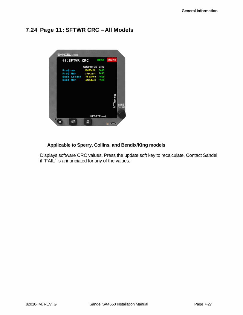
General Information
82010-IM, REV. G Sandel SA4550 Installation Manual Page 7-27
7.24 Page 11: SFTWR CRC – All Models
Applicable to Sperry, Collins, and Bendix/King models
Displays software CRC values. Press the update soft key to recalculate. Contact Sandel if “FAIL” is annunciated for any of the values.
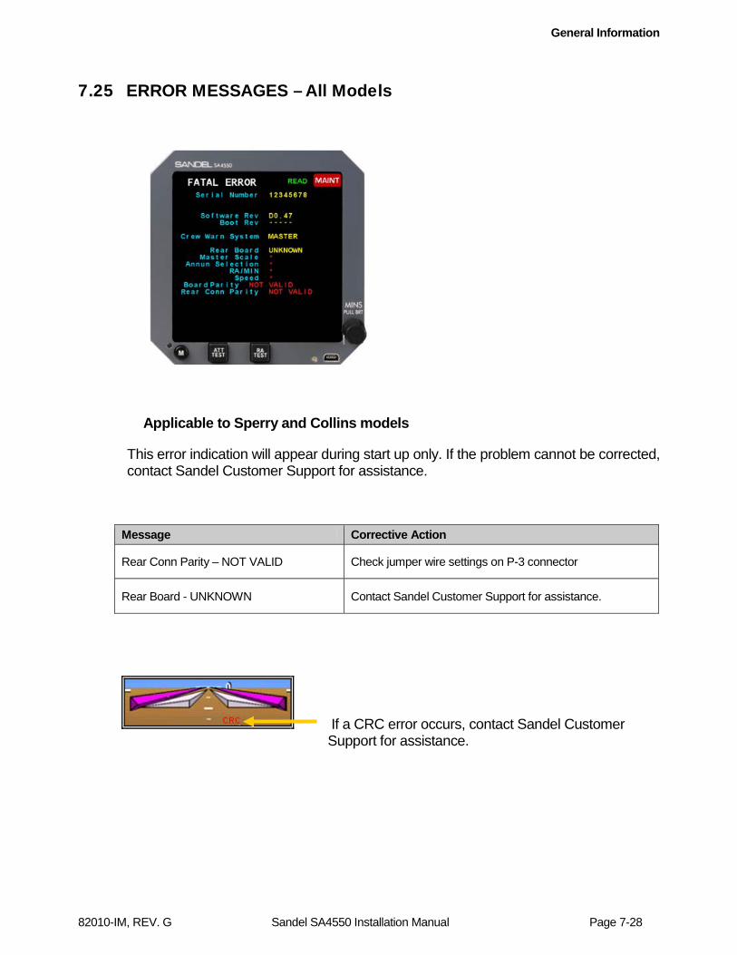
General Information
82010-IM, REV. G Sandel SA4550 Installation Manual Page 7-28
7.25 ERROR MESSAGES – All Models
Applicable to Sperry and Collins models
This error indication will appear during start up only. If the problem cannot be corrected, contact Sandel Customer Support for assistance.
Message Corrective Action
Rear Conn Parity – NOT VALID Check jumper wire settings on P-3 connector
Rear Board - UNKNOWN Contact Sandel Customer Support for assistance.
If a CRC error occurs, contact Sandel Customer Support for assistance.
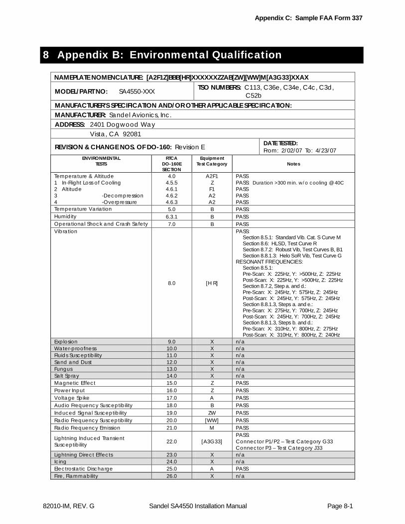
Appendix C: Sample FAA Form 337
82010-IM, REV. G Sandel SA4550 Installation Manual Page 8-1
8 Appendix B: Environmental Qualification
NAMEPLATE NOMENCLATURE: [A2F1Z]BBB[HR]XXXXXXZZAB[ZW][WW]M[A3G33]XXAX
MODEL/PART NO: SA4550-XXX TSO NUMBERS: C113, C36e, C34e, C4c, C3d, C52b
MANUFACTURER’S SPECIFICATION AND/OR OTHER APPLICABLE SPECIFICATION: MANUFACTURER: Sandel Avionics, Inc. ADDRESS: 2401 Dogwood Way Vista, CA 92081
REVISION & CHANGE NOS. OF DO-160: Revision E DATE TESTED: From: 2/02/07 To: 4/23/07
ENVIRONMENTAL TESTS
RTCA DO-160E SECTION
Equipment Test Category Notes
Temperature & Altitude 1 In-Flight Loss of Cooling 2 Altitude 3 -Decompression 4 -Overpressure
4.0 4.5.5 4.6.1 4.6.2 4.6.3
A2F1 Z
F1 A2 A2
PASS PASS: Duration >300 min. w/o cooling @ 40C PASS PASS PASS
Temperature Variation 5.0 B PASS: Humidity 6.3.1 B PASS Operational Shock and Crash Safety 7.0 B PASS Vibration
8.0 [H R]
PASS: Section 8.5.1: Standard Vib. Cat. S Curve M Section 8.6: HLSD, Test Curve R Section 8.7.2: Robust Vib, Test Curves B, B1 Section 8.8.1.3: Helo SoR Vib, Test Curve G RESONANT FREQUENCIES: Section 8.5.1: Pre-Scan: X: 225Hz, Y: >500Hz, Z: 225Hz Post-Scan: X: 225Hz, Y: >500Hz, Z: 225Hz Section 8.7.2, Step a. and d.: Pre-Scan: X: 245Hz, Y: 575Hz, Z: 245Hz Post-Scan: X: 245Hz, Y: 575Hz, Z: 245Hz Section 8.8.1.3, Steps a. and e.: Pre-Scan: X: 275Hz, Y: 700Hz, Z: 245Hz Post-Scan: X: 245Hz, Y: 700Hz, Z: 245Hz Section 8.8.1.3, Steps b. and d.: Pre-Scan: X: 310Hz, Y: 800Hz, Z: 275Hz Post-Scan: X: 310Hz, Y: 800Hz, Z: 240Hz
Explosion 9.0 X n/a Water-proofness 10.0 X n/a Fluids Susceptibility 11.0 X n/a Sand and Dust 12.0 X n/a Fungus 13.0 X n/a Salt Spray 14.0 X n/a Magnetic Effect 15.0 Z PASS Power Input 16.0 Z PASS Voltage Spike 17.0 A PASS Audio Frequency Susceptibility 18.0 B PASS Induced Signal Susceptibility 19.0 ZW PASS Radio Frequency Susceptibility 20.0 [WW] PASS Radio Frequency Emission 21.0 M PASS
Lightning Induced Transient Susceptibility 22.0 [A3G33]
PASS: Connector P1/P2 – Test Category G33 Connector P3 – Test Category J33
Lightning Direct Effects 23.0 X n/a Icing 24.0 X n/a Electrostatic Discharge 25.0 A PASS Fire, Flammability 26.0 X n/a

Appendix C: Sample FAA Form 337
82010-IM, REV. G Sandel SA4550 Installation Manual Page 9-2
9 Appendix C: Sample FAA Form 337
NOTICE
Weight and balance or operating limitation changes shall be entered in the appropriate aircraft record. An alteration must be compatible with all previous alterations to assure continued conformity with the applicable airworthiness requirements.
8. Description of Work Accomplished (If more space is required, attach additional sheets. Identify with aircraft nationality and
registration mark and date work completed.) A. Installed the following equipment and components: 1. Sandel Avionics, Inc., SA4550 Primary Attitude Display (or as appropriate), Part
Number SA4550-(XXX) (or as appropriate) 2. Sandel Avionics, Inc., Clamp Fixture 4ATI, Part Number 61186. B. The Sandel Avionics SA4550 is interfaced to the following equipment: 1. (List as appropriate) (By example state the following functional interface properties)... C. Interference and functional tests and inspections were accomplished with reference
to Advisory Circular 2X.1311. (or as appropriate). D. A system design and analysis was conducted with reference to Advisory Circular
2X.1309-1( ). (or as appropriate). E. The pertinent Federal Aviation Regulations for the installation performed, 2X.1301,
2X.1309, 23.1311, 2X.1321, 2X.1322, 25.1329, 2X.1331, 23.1335, 2X1351, 2X.1357, 23.1365, 2X.1381, 2X.1529, and 2X.1581 (or as appropriate), were the basis of compliance.
F. The aircraft equipment list, and weight and balance were revised and recorded within
the aircraft maintenance records. G. All pertinent records of this alteration are on file at (State your repair station name and
number). -------------------------------------------------------- End ------------------------------------------------

Appendix D: Airplane Flight Manual Supplement
82010-IM, REV. G Sandel SA4550 Installation Manual Page 10-1
10 Appendix D: Airplane Flight Manual Supplement
Reference Sandel document ST12361LA-T-10, “SA4550 Primary Attitude Display Aircraft Flight Manual Supplement”.

Appendix E: Checkout Procedures
82010-IM, REV. G Sandel SA4550 Installation Manual Page 11-1
11 Appendix E: Checkout Procedures
11.1 Functional Ground Test Procedures/Report
The “Functional Ground Test Procedures/Report” below is for the purpose of simplifying ground tests of the SA4550. A copy of this report (and the “Operational Flight Check Procedures/ Report”) must be retained by the installing agency and a copy must be installed in the aircraft maintenance records. A copy must also be forwarded to Sandel Avionics, Inc. along with the Warranty Registration Form, Part Number 82010-0137, which should be mailed after operational acceptance.
Date Performed:
Repair Station Name
Number
Address or Location
City ST ZIP
A/C Make: A/C Model: A/C Serial No:
Work Order No. Technician:

Appendix E: Checkout Procedures
82010-IM, REV. G Sandel SA4550 Installation Manual Page 11-2
COMPANY NAME COMPANY ADDRESS TELEPHONE/FAX
Ground Test Procedures/Report for
Sandel Avionics SA4550 Primary Attitude Display
Installed in {Aircraft make and model}
Registration No. Serial No.
Document No. Rev. Date
Appendix E: Checkout Procedures
82010-IM, REV. G Sandel SA4550 Installation Manual Page 11-3
11.1.1 Introduction
The following ground test procedures are to be performed after the SA4550 has been properly configured in the “Post-Installation Procedures”, but prior to performing flight test procedures. Successful completion of both the Ground Test and Flight Test procedures is necessary to support the claim that the SA4550, as installed, performs its intended function and is compatible with all aircraft systems. The ground test procedures contained herein will include testing of interfaces to other systems. Therefore, this ground test must be conducted in conjunction with, or subsequent to ground testing of other systems. The following external system interfaces will be tested as installed: - Attitude input from vertical gyro - Flight Director - Localizer and Glide Slope inputs. - Rad/Alt display and Min annunciator input from a radar altimeter. - GA annunciator input from a go around button. - Angle of attack. - Mode Annunciators. - External NVIS control switch (if installed) Record the following information: SA4550 Serial Number(s):
Software Version:
11.1.2 Physical Installation
Verify that the SA4550 clamp has been properly installed in accordance with the manufacturer’s instructions, that any external switches affecting SA4550 operation have been clearly labeled, and that a trip-free re-settable circuit breaker labeled “ADI” is clearly visible. Ensure that cooling air intake is not obstructed. Completed _______ Comment __________________________________
11.1.3 Wiring Verification and Initial Power-Up
Perform a 100% continuity check of all aircraft wiring to verify in accordance with installation wiring diagrams. Completed _______ Comment __________________________________

Appendix E: Checkout Procedures
82010-IM, REV. G Sandel SA4550 Installation Manual Page 11-4
Power check all wiring to ensure that 28 Vdc is applied to the proper pins and nowhere else. Completed _______ Comment __________________________________ Install the SA4550 into the clamp tray and verify full connector mating and that the unit installs without obstruction. Completed _______ Comment __________________________________
11.1.4 System Functions
Activate the aircraft master switch. Verify that the SA4550 display illuminates within 30 seconds. Do not activate the AC power switch. Completed Comment
Verify that the SA4550 does not display attitude information and displays an attitude flag. Completed Comment
Activate the AC power switch. Verify that the position of the horizon is proper for the attitude of the aircraft. Allow 5 minutes for the aircraft vertical gyro to initialize. Completed Comment
Verify that the ball of the Slip/Skid indicator on the SA4550 is proper for the attitude of the aircraft. Completed Comment ______________________________________
Verify that the radar altimeter indication on the SA4550 is 50 feet (or appropriate indication for the Radar altimeter installed) when the radar altimeter test is activated. Depending on equipment installed (some installations will cause the normal display to flag when under test) it may be necessary to use the RADALT maintenance page 7 to verify the RADALT value. For ARINC 429 radar altimeter installations, verify that the text “RADALT” in the radar altimeter window is replaced with the text “RA TEST” in amber while the system is under test. Completed Comment Using a radar altimeter ground test set, verify full altitude range (IAW installed equipment) with the radar altimeter indication on the SA4550. If a test set is not available verify the radar altimeter display during the first flight. See flight test procedures.

Appendix E: Checkout Procedures
82010-IM, REV. G Sandel SA4550 Installation Manual Page 11-5
Completed Comment
Press the ATT test button and verify that the pitch and roll change by 10 degrees, the slip skid ball deflects full right and that the text “RED GREEN BLUE” appear in their respective colors. Continue pressing the ATT test button and verify that the display blanks and after releasing the test button the display illuminates again. Completed Comment
Verify that the MIN indication on the SA4550 changes when the MIN knob is rotated. Completed Comment
Determine that all associated equipment such as ILS receivers initialize and function normally. Completed Comment
Verify that the SA4550 internal brightness control can control the brightness of the SA4550 and that a satisfactory brightness level can be attained. Completed Comment
Evaluate the display of the SA4550 for readability. Completed Comment
Evaluate the intensity properties of the SA4550 display under both direct and indirect sunlight conditions, and in nighttime operation conditions. Completed Comment
11.1.5 Attitude Check Pitch & Roll
Tilt the aircraft attitude gyro slowly about the pitch axis. Confirm that the pitch attitude displayed on the SA4550 matches the direction of the gyro movement. Completed Comment
Tilt the aircraft attitude gyro slowly about the roll axis. Confirm that the roll attitude displayed on the SA4550 matches the direction of the gyro movement. Completed Comment
Appendix E: Checkout Procedures
82010-IM, REV. G Sandel SA4550 Installation Manual Page 11-6
11.1.6 Flight Computer Interface
If equipped, engage the “Go Around” (GA) mode and verify the Flight director indicates a positive pitch up and the GA annunciator on the SA4550 is displayed. Completed Comment
If equipped place the FD mode selector in heading (HDG) mode with the flight director ON and autopilot OFF. Move the heading bug to the lubber line and verify the flight director command cue the SA4550 is level. Verify that the SA4550 flight director cue indicates a left bank when the heading bug is moved to the left of the lubber line, and that the SA4550 flight director cue indicates a right bank when the heading bug is moved to the right of the lubber line. Completed Comment
If equipped, disengage the RADAR Altimeter (RA) circuit breaker (CB). With the Flight Computer on, place the FD mode selector in APPR mode. The autopilot should be OFF. Using a ground test set, provide a centered Localizer (LOC) and Glide Slope (GS) signal and allow the Flight Computer to capture. Verify that changing the LOC deviation left and right causes the Flight Director cue to correctly indicate a left and right bank command and that changing the GS deviation up and down causes the Flight Director cue to correctly indicate a positive and negative pitch angle. Completed Comment Detune the ILS frequency for the NAV receiver interfaced to the SA4550 and verify the LOC and GS scales are removed from the SA4550. Completed Comment Tune an ILS frequency on NAV receiver interfaced to the SA4550 and verify the LOC and GS scales are displayed on the SA4550. Completed Comment Using a ground test set, invalidate the LOC signal. Verify the LOC flag is displayed on the SA4550. Completed Comment Using a ground test set, invalidate the (GS) signal. Verify the GS flag is displayed on the SA4550. Completed Comment

Appendix E: Checkout Procedures
82010-IM, REV. G Sandel SA4550 Installation Manual Page 11-7
If equipped disengage the Flight Computer CB and verify the COMPUTER flag is displayed on the SA4550.
Note: For KCI-310 replacements, when pulling the Flight Computer CB, the COMPUTER flag may only briefly come into view. This is normal behavior and will cause the FD bars and flag to be cleared from the display. Other installations may exhibit similar behaviour. Flag inputs with high level validity input requirements will not be able to sustain the flag when the circuit breaker is pulled since the driving unit no longer has power. In these cases, alternative methods will be necessary to force the flagged state.
Completed Comment Re-engage the Flight Computer CB and verify the COMPUTER flag is removed on the SA4550.
Completed Comment If equipped disengage the RA circuit breaker and verify the SA4550 RA display is flagged. A dashed line should appear on the SA4550 RA display.
Completed Comment Re-engage the RA CB and verify the flag is removed on the SA4550 RA display. Completed Comment
11.1.7 Mode Annunciators If mode annunciators are supported and installed, configure the aircraft system to enable the pertinent SA4550 annunciators. Verify correct annunciator display.
Completed Comment
List all SA4550 annunciators configured in this installation.
11.1.8 Angle of Attack Indicator

Appendix E: Checkout Procedures
82010-IM, REV. G Sandel SA4550 Installation Manual Page 11-8
If equipped center the Fast/Slow indicator on the SA4550 by rotating the angle-of-attack transmitter (ICAW the aircraft maintenance procedures). Completed Comment Rotate the angle-of-attack transmitter in a clockwise direction (in accordance with the aircraft maintenance procedures) as viewed from the outside of the airplane. Verify the Fast/Slow indicator on the SA4550 moves downward to indicate a slow condition. Completed Comment Rotate the angle-of-attack transmitter in a counterclockwise direction (ICAW the aircraft maintenance procedures) as viewed from the outside of the airplane. Verify the Fast/Slow indicator on the SA4550 moves upward to indicate a fast condition. Completed Comment Disengage the angle-of-attack CB. Verify the speed flag appears on the SA4550. Completed Comment Engage the angle-of-attack CB. Verify the speed flag disappears on the SA4550. Completed Comment Reset the angle-of-attack transmitter to its original position (IAW the aircraft maintenance procedures). Completed Comment
11.1.9 NVIS Control
If the SA4550 supports NVIS compatibility, (SA4550-XXXN).
Activate the external NVIS control switch and verify “NVIS” is annunciated on the lower right of the screen.
Completed _______ Comment __________________________________
11.1.10 Additional Testing
Perform any additional tests deemed necessary. Completed Comment
Appendix E: Checkout Procedures
82010-IM, REV. G Sandel SA4550 Installation Manual Page 11-9
11.2 EMI/RFI Test Procedures
11.2.1 NAV/COM Testing
Apply power to the avionics bus and ensure that all electrical equipment, including the SA4550, is operating normally. Open the squelch on the primary communications radio and tune the radio to each whole megahertz frequency sequentially. Attempt to discern any interference caused by the SA4550. Pull the SA4550 breaker if interference is noted, to verify that the SA4550 is the source. Completed _______ Comment __________________________________ Repeat for the secondary communications radio. Completed _______ Comment __________________________________ Tune the primary navigation radio to 112 MHz and enable the audio output. Attempt to discern any audible interference cause by the SA4550. Completed _______ Comment __________________________________ Repeat for the secondary navigation radio. Completed _______ Comment __________________________________ Transmit on the frequencies 118.000 MHz, 126.975 MHz, and 135.975 MHz on the primary communications radio and attempt to discern any changes in the SA4550 display. Completed _______ Comment __________________________________ Repeat for the secondary communications radio. Completed _______ Comment __________________________________
11.2.2 General Testing
Observe any unusual interaction between the transponder, DME, ADF or Marker Beacon receivers, and the SA4550 when switching power to any equipment. Completed _______ Comment __________________________________

Appendix E: Checkout Procedures
82010-IM, REV. G Sandel SA4550 Installation Manual Page 11-10
11.2.3 Additional Testing
Perform any additional EMI/RFI-related tests deemed necessary. Completed _______ Comment __________________________________

Appendix E: Checkout Procedures
82010-IM, REV. G Sandel SA4550 Installation Manual Page 11-11
11.3 Operational Flight Test Procedures/Report
The following “Operational Flight Check Procedures/Report” is for the purpose of simplifying the in-flight operational check of the SA4550. A copy of this report (and the “Functional Ground Test Procedures/ Report”) must be retained by the installing agency and a copy must be installed in the aircraft maintenance records. A copy must also be forwarded to Sandel Avionics along with the Warranty Registration Form, Part Number 82010-0137, which should be mailed after operational acceptance.

Appendix E: Checkout Procedures
82010-IM, REV. G Sandel SA4550 Installation Manual Page 11-12
COMPANY NAME COMPANY ADDRESS TELEPHONE/FAX
Flight Test Procedures/Report for
Sandel Avionics SA4550 Primary Attitude Display
Installed in {Aircraft make and model}
Registration No. Serial No.
Document No. Rev. Date
Appendix E: Checkout Procedures
82010-IM, REV. G Sandel SA4550 Installation Manual Page 11-13
11.4 Introduction
The Flight Test Procedures described below are to be performed after both the Post-Install Procedures and the Ground Test Procedures are performed. Successful completion of the Flight Test Procedures will then satisfy the criteria for operational acceptance of the SA4550 installation.
Specific procedures are not provided for many of the tests herein, due to differences in installed options and aircraft configurations. Refer to the SA4550 Pilot’s Guide and the proposed Airplane Flight Manual Supplement for operational details of the equipment.
Each test item is followed by a space for the initials of the person performing the procedure, and a space for a description of any observations or anomalies. Determination of a successful flight test is made after analysis of these observations.
11.5 Test Procedures
Record the following information: SA4550 Serial Number(s):
Software Version:
11.5.1 Pre - Departure Operations
Apply power to the SA4550 and all associated equipment. Determine that all equipment initializes and functions normally. Completed _______ Comment __________________________________ Prior to the Attitude Gyro initialization has been completed, verify the SA4550 does not indicate an attitude and the SA4550 attitude is flagged. Completed _______ Comment __________________________________ After the Attitude Gyro has completed initialization, verify the SA4550 indicates the correct attitude. Completed _______ Comment __________________________________ Verify that the SA4550 internal brightness control can control the brightness of the SA4550 and that a satisfactory brightness level can be achieved. Completed _______ Comment __________________________________
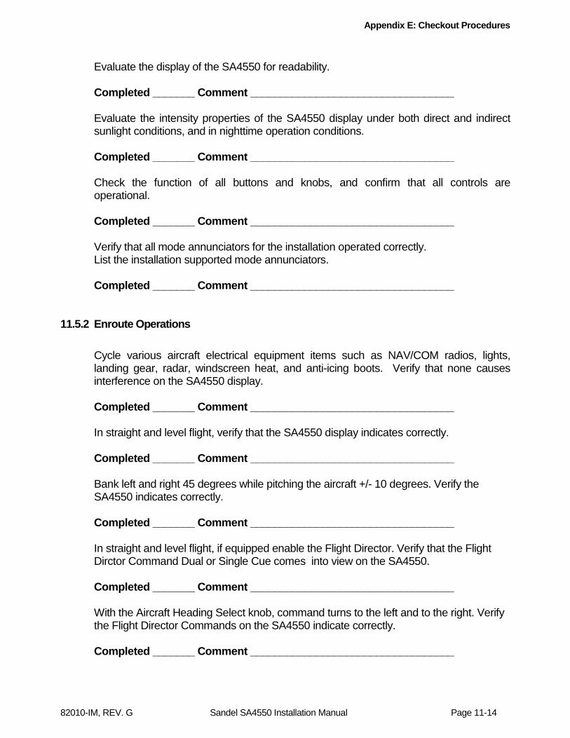
Appendix E: Checkout Procedures
82010-IM, REV. G Sandel SA4550 Installation Manual Page 11-14
Evaluate the display of the SA4550 for readability. Completed _______ Comment __________________________________ Evaluate the intensity properties of the SA4550 display under both direct and indirect sunlight conditions, and in nighttime operation conditions. Completed _______ Comment __________________________________ Check the function of all buttons and knobs, and confirm that all controls are operational. Completed _______ Comment __________________________________ Verify that all mode annunciators for the installation operated correctly. List the installation supported mode annunciators. Completed _______ Comment __________________________________
11.5.2 Enroute Operations
Cycle various aircraft electrical equipment items such as NAV/COM radios, lights, landing gear, radar, windscreen heat, and anti-icing boots. Verify that none causes interference on the SA4550 display. Completed _______ Comment __________________________________ In straight and level flight, verify that the SA4550 display indicates correctly. Completed _______ Comment __________________________________ Bank left and right 45 degrees while pitching the aircraft +/- 10 degrees. Verify the SA4550 indicates correctly. Completed _______ Comment __________________________________ In straight and level flight, if equipped enable the Flight Director. Verify that the Flight Dirctor Command Dual or Single Cue comes into view on the SA4550. Completed _______ Comment __________________________________ With the Aircraft Heading Select knob, command turns to the left and to the right. Verify the Flight Director Commands on the SA4550 indicate correctly. Completed _______ Comment __________________________________
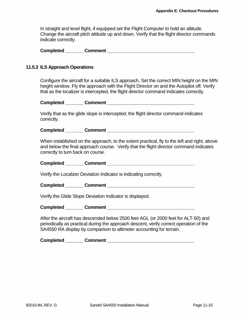
Appendix E: Checkout Procedures
82010-IM, REV. G Sandel SA4550 Installation Manual Page 11-15
In straight and level flight, if equipped set the Flight Computer to hold an altitude. Change the aircraft pitch attitude up and down. Verify that the flight director commands indicate correctly. Completed _______ Comment __________________________________
11.5.3 ILS Approach Operations
Configure the aircraft for a suitable ILS approach. Set the correct MIN height on the MIN height window. Fly the approach with the Flight Director on and the Autopilot off. Verify that as the localizer is intercepted, the flight director command indicates correctly. Completed _______ Comment __________________________________ Verify that as the glide slope is intercepted, the flight director command indicates correctly. Completed _______ Comment __________________________________ When established on the approach, to the extent practical, fly to the left and right, above and below the final approach course. Verify that the flight director command indicates correctly to turn back on course. Completed _______ Comment __________________________________ Verify the Localizer Deviation Indicator is indicating correctly. Completed _______ Comment __________________________________ Verify the Glide Slope Deviation Indicator is displayed. Completed _______ Comment __________________________________ After the aircraft has descended below 2500 feet AGL (or 2000 feet for ALT-50) and periodically as practical during the approach descent, verify correct operation of the SA4550 RA display by comparison to altimeter accounting for terrain. Completed _______ Comment __________________________________
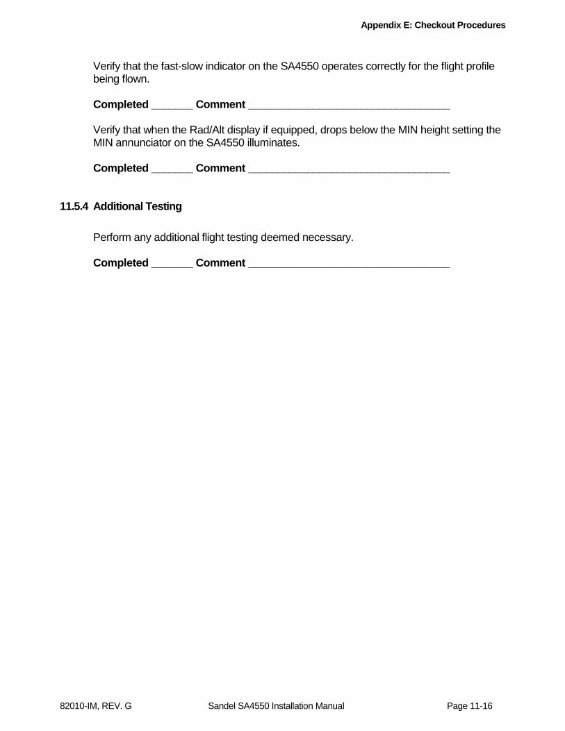
Appendix E: Checkout Procedures
82010-IM, REV. G Sandel SA4550 Installation Manual Page 11-16
Verify that the fast-slow indicator on the SA4550 operates correctly for the flight profile being flown. Completed _______ Comment __________________________________ Verify that when the Rad/Alt display if equipped, drops below the MIN height setting the MIN annunciator on the SA4550 illuminates. Completed _______ Comment __________________________________
11.5.4 Additional Testing
Perform any additional flight testing deemed necessary. Completed _______ Comment __________________________________
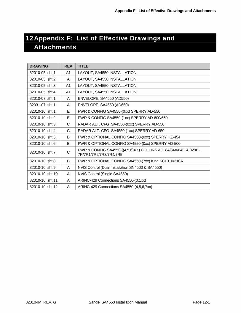
Appendix F: List of Effective Drawings and Attachments
82010-IM, REV. G Sandel SA4550 Installation Manual Page 12-1
12 Appendix F: List of Effective Drawings and Attachments
DRAWING REV TITLE 82010-05, sht 1 A1 LAYOUT, SA4550 INSTALLATION 82010-05, sht 2 A LAYOUT, SA4550 INSTALLATION 82010-05, sht 3 A1 LAYOUT, SA4550 INSTALLATION 82010-05, sht 4 A1 LAYOUT, SA4550 INSTALLATION 82010-07, sht 1 A ENVELOPE, SA4550 (AD550) 82031-07, sht 1 A ENVELOPE, SA4550 (AD650) 82010-10, sht 1 E PWR & CONFIG SA4550-(0xx) SPERRY AD-550 82010-10, sht 2 E PWR & CONFIG SA4550-(1xx) SPERRY AD-600/650 82010-10, sht 3 C RADAR ALT. CFG SA4550-(0xx) SPERRY AD-550 82010-10, sht 4 C RADAR ALT. CFG SA4550-(1xx) SPERRY AD-650 82010-10, sht 5 B PWR & OPTIONAL CONFIG SA4550-(0xx) SPERRY HZ-454 82010-10, sht 6 B PWR & OPTIONAL CONFIG SA4550-(0xx) SPERRY AD-500
82010-10, sht 7 C PWR & CONFIG SA4550-((4,5,6)XX) COLLINS ADI 84/84A/84C & 329B-7R/7R1/7R2/7R3/7R4/7R5
82010-10, sht 8 B PWR & OPTIONAL CONFIG SA4550-(7xx) King KCI 310/310A 82010-10, sht 9 A NVIS Control (Dual Installation SN4500 & SA4550) 82010-10, sht 10 A NVIS Control (Single SA4550) 82010-10, sht 11 A ARINC-429 Connections SA4550-(0,1xx) 82010-10, sht 12 A ARINC-429 Connections SA4550-(4,5,6,7xx)
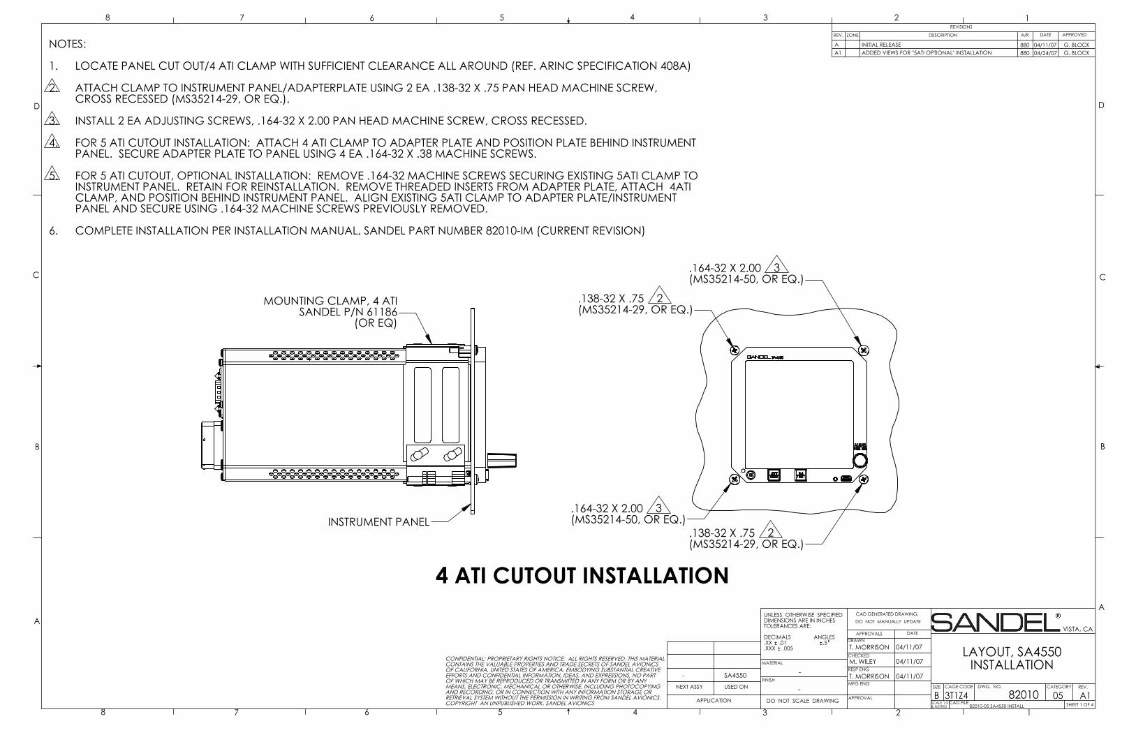
.164-32 X 2.00 3(MS35214-50, OR EQ.)
.138-32 X .75 2(MS35214-29, OR EQ.)
.138-32 X .75 2(MS35214-29, OR EQ.)
.164-32 X 2.00 3(MS35214-50, OR EQ.)
4 ATI CUTOUT INSTALLATION
INSTRUMENT PANEL
MOUNTING CLAMP, 4 ATISANDEL P/N 61186
(OR EQ)
D
C
B
AA
B
C
D
CAD GENERATED DRAWING,DO NOT MANUALLY UPDATE
SCALE 1:2& NOTED
SIZE CAGE CODE
BSHEET 1 OF 4
REV.
LAYOUT, SA4550INSTALLATION
DATEAPPROVALSDRAWN
CHECKED
RESP ENG
MFG ENG
APPROVAL
UNLESS OTHERWISE SPECIFIEDDIMENSIONS ARE IN INCHESTOLERANCES ARE:
DECIMALS ANGLES.XX .01 .5.XXX .005
MATERIAL
FINISH-
DO NOT SCALE DRAWINGAPPLICATION
USED ONNEXT ASSY
12345678
8 7 6 5 4 3 2 1REVISIONS
REV. DESCRIPTION APPROVED
VISTA, CA
A182010
T. MORRISON
DWG. NO.
3T1Z4-
NOTES:
LOCATE PANEL CUT OUT/4 ATI CLAMP WITH SUFFICIENT CLEARANCE ALL AROUND (REF. ARINC SPECIFICATION 408A)1.
ATTACH CLAMP TO INSTRUMENT PANEL/ADAPTERPLATE USING 2 EA .138-32 X .75 PAN HEAD MACHINE SCREW,2.CROSS RECESSED (MS35214-29, OR EQ.).
INSTALL 2 EA ADJUSTING SCREWS, .164-32 X 2.00 PAN HEAD MACHINE SCREW, CROSS RECESSED.3.
FOR 5 ATI CUTOUT INSTALLATION: ATTACH 4 ATI CLAMP TO ADAPTER PLATE AND POSITION PLATE BEHIND INSTRUMENT4.PANEL. SECURE ADAPTER PLATE TO PANEL USING 4 EA .164-32 X .38 MACHINE SCREWS.
FOR 5 ATI CUTOUT, OPTIONAL INSTALLATION: REMOVE .164-32 MACHINE SCREWS SECURING EXISTING 5ATI CLAMP TO5.INSTRUMENT PANEL. RETAIN FOR REINSTALLATION. REMOVE THREADED INSERTS FROM ADAPTER PLATE, ATTACH 4ATI CLAMP, AND POSITION BEHIND INSTRUMENT PANEL. ALIGN EXISTING 5ATI CLAMP TO ADAPTER PLATE/INSTRUMENTPANEL AND SECURE USING .164-32 MACHINE SCREWS PREVIOUSLY REMOVED.
COMPLETE INSTALLATION PER INSTALLATION MANUAL, SANDEL PART NUMBER 82010-IM (CURRENT REVISION)6.
M. WILEY
T. MORRISON
04/11/07
04/11/07
04/11/07
82010-05 SA4550 INSTALL
CONFIDENTIAL: PROPRIETARY RIGHTS NOTICE: ALL RIGHTS RESERVED. THIS MATERIALCONTAINS THE VALUABLE PROPERTIES AND TRADE SECRETS OF SANDEL AVIONICSOF CALIFORNIA, UNITED STATES OF AMERICA, EMBODYING SUBSTANTIAL CREATIVEEFFORTS AND CONFIDENTIAL INFORMATION, IDEAS, AND EXPRESSIONS, NO PARTOF WHICH MAY BE REPRODUCED OR TRANSMITTED IN ANY FORM OR BY ANYMEANS, ELECTRONIC, MECHANICAL OR OTHERWISE, INCLUDING PHOTOCOPYINGAND RECORDING, OR IN CONNECTION WITH ANY INFORMATION STORAGE ORRETRIEVAL SYSTEM WITHOUT THE PERMISSION IN WRITING FROM SANDEL AVIONICS.COPYRIGHT AN UNPUBLISHED WORK. SANDEL AVIONICS CAD FILE
-
INITIAL RELEASEA
ZONE
SA4550
G. BLOCK04/11/07 G. BLOCK
CATEGORY
05
DATEA/R
880A1 880 04/24/07ADDED VIEWS FOR "5ATI OPTIONAL" INSTALLATION
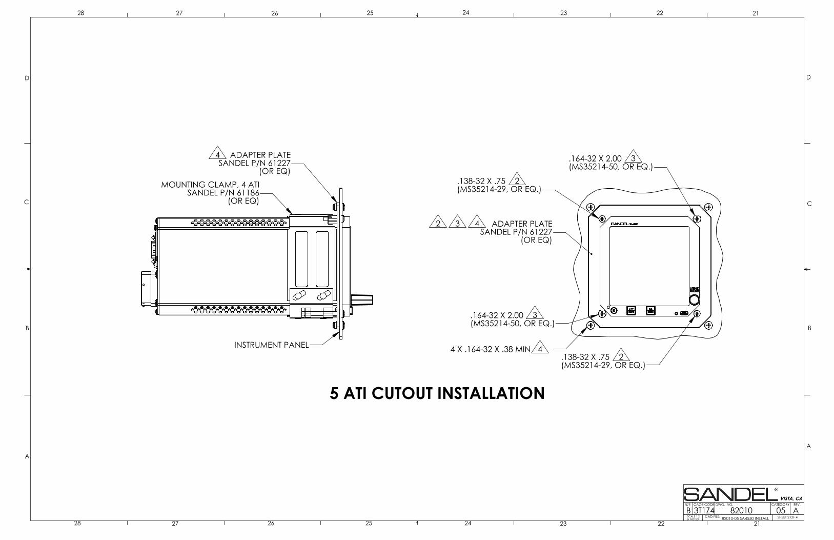
.164-32 X 2.00 3(MS35214-50, OR EQ.)
.138-32 X .75 2(MS35214-29, OR EQ.)
.138-32 X .75 2(MS35214-29, OR EQ.)
.164-32 X 2.00 3(MS35214-50, OR EQ.)
2 3 4 ADAPTER PLATESANDEL P/N 61227
(OR EQ)
4 X .164-32 X .38 MIN 4INSTRUMENT PANEL
MOUNTING CLAMP, 4 ATISANDEL P/N 61186
(OR EQ)
4 ADAPTER PLATESANDEL P/N 61227
(OR EQ)
5 ATI CUTOUT INSTALLATION
D
C
B
AA
B
C
D
SCALE 1:2& NOTED
SIZE CAGE CODE
BREV.
2122232425262728
28 27 26 25 24 23 22 21
VISTA, CA
82010 ADWG. NO.
3T1Z4SHEET 2 OF 4CAD FILE: 82010-05 SA4550 INSTALL05
CATEGORY

.164-32 X 2.00 3(MS35214-50, OR EQ.)
.138-32 X .75 2(MS35214-29, OR EQ.)
.138-32 X .75 2(MS35214-29, OR EQ.)
.164-32 X 2.00 3(MS35214-50, OR EQ.)
2 3 5 ADAPTER PLATESANDEL P/N 61227
(OR EQ)
4 X .164-32 5
INSTRUMENT PANEL
MOUNTING CLAMP, 4 ATISANDEL P/N 61186
(OR EQ)
5 ADAPTER PLATESANDEL P/N 61227
(OR EQ)
5 ATI CUTOUT, OPTIONAL INSTALLATION(RETAINS EXISTING 5ATI CLAMP BEHIND INSTRUMENT PANEL)
5 EXISTING 5ATI CLAMP(ARINC 408 7" SHELF TYPE SHOWN,ACTUAL INSTALLATION MAY VARY)
SA4550
HARDWARE FROMEXISTING 5ATI CLAMP
INSTRUMENT PANEL(.100 NOM. THICKNESS)
61227 ADAPTER PLATE(INSERTS REMOVED)
W/61186 4ATI CLAMP
EXISTING 5ATICLAMP
D
C
B
AA
B
C
D
SCALE 1:2& NOTED
SIZE CAGE CODE
BREV.
3132333435363738
38 37 36 35 34 33 32 31
VISTA, CA
82010 A1DWG. NO.
3T1Z4SHEET 3 OF 4CAD FILE: 82010-05 SA4550 INSTALL05
CATEGORY
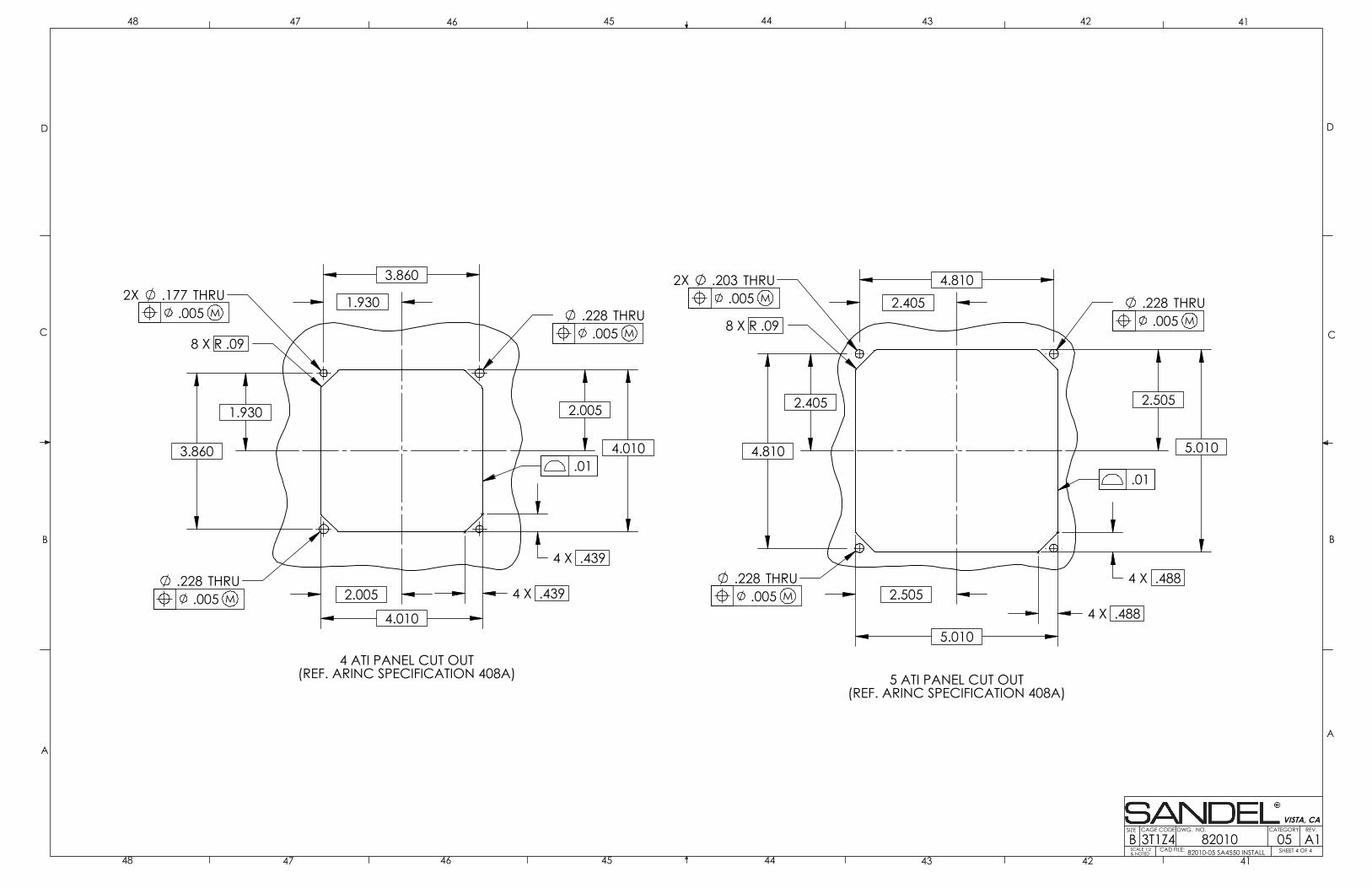
4.010
3.860
3.860
8 X R .09
4.010
.228 THRU2X .177 THRU
.228 THRU 2.005
2.005
4 X .439
4 X .439
1.930
1.930
4 ATI PANEL CUT OUT(REF. ARINC SPECIFICATION 408A)
.005 M
.01
.005 M
.005 M
5.010
8 X R .09
5.010
4.810
4.810
2X .203 THRU .228 THRU
.228 THRU 2.505
2.505
4 X .488
4 X .488
2.405
2.405
5 ATI PANEL CUT OUT(REF. ARINC SPECIFICATION 408A)
.01
.005 M
.005 M
.005 M
D
C
B
AA
B
C
D
SCALE 1:2& NOTED
SIZE CAGE CODE
BREV.
4142434445464748
48 47 46 45 44 43 42 41
VISTA, CA
82010 A1DWG. NO.
3T1Z4SHEET 4 OF 4CAD FILE: 82010-05 SA4550 INSTALL05
CATEGORY
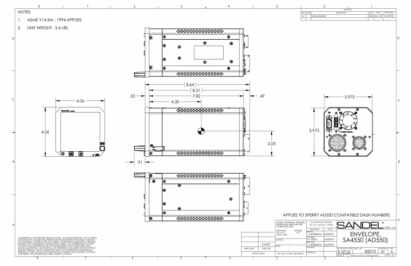
4.06
4.06
.33 7.82
.91
8.318.64
.494.30
2.05
3.975
3.975
D
C
B
AA
B
C
D
CAD GENERATED DRAWING,DO NOT MANUALLY UPDATE
SCALE 1:2& NOTED
SIZE CAGE CODE
BSHEET 1 OF 1
REV.
ENVELOPE,SA4550 (AD550)
DATEAPPROVALSDRAWN
CHECKED
RESP ENG
MFG ENG
APPROVAL
UNLESS OTHERWISE SPECIFIEDDIMENSIONS ARE IN INCHESTOLERANCES ARE:
DECIMALS ANGLES.XX .01 .5.XXX .005
MATERIAL
FINISH-
DO NOT SCALE DRAWINGAPPLICATION
USED ONNEXT ASSY
12345678
8 7 6 5 4 3 2 1REVISIONS
REV. DESCRIPTION APPROVED
VISTA, CA
A82010
T. MORRISON
DWG. NO.
3T1Z4
G
-
M. WILEY
T. MORRISON
04/09/07
04/09/07
04/09/07
82010-07 LAYOUT, SA4550 (AD550)
CONFIDENTIAL: PROPRIETARY RIGHTS NOTICE: ALL RIGHTS RESERVED. THIS MATERIALCONTAINS THE VALUABLE PROPERTIES AND TRADE SECRETS OF SANDEL AVIONICSOF CALIFORNIA, UNITED STATES OF AMERICA, EMBODYING SUBSTANTIAL CREATIVEEFFORTS AND CONFIDENTIAL INFORMATION, IDEAS, AND EXPRESSIONS, NO PARTOF WHICH MAY BE REPRODUCED OR TRANSMITTED IN ANY FORM OR BY ANYMEANS, ELECTRONIC, MECHANICAL OR OTHERWISE, INCLUDING PHOTOCOPYINGAND RECORDING, OR IN CONNECTION WITH ANY INFORMATION STORAGE ORRETRIEVAL SYSTEM WITHOUT THE PERMISSION IN WRITING FROM SANDEL AVIONICS.COPYRIGHT AN UNPUBLISHED WORK. SANDEL AVIONICS CAD FILE
-
INITIAL RELEASEA
ZONE
SA4550
04/11/07 G. BLOCK
CATEGORY
07
DATEA/R
880
NOTES:
ASME Y14.5M - 1994 APPLIES1.
UNIT WEIGHT: 3.4 LBS.2.
APPLIES TO SPERRY AD550 COMPATIBLE DASH NUMBERS

4.06
4.06
.33 7.51
.91
8.188.50
.674.30
2.05
3.975
3.975
D
C
B
AA
B
C
D
CAD GENERATED DRAWING,DO NOT MANUALLY UPDATE
SCALE 1:2& NOTED
SIZE CAGE CODE
BSHEET 1 OF 1
REV.
ENVELOPE,SA4550 (AD650)
DATEAPPROVALSDRAWN
CHECKED
RESP ENG
MFG ENG
APPROVAL
UNLESS OTHERWISE SPECIFIEDDIMENSIONS ARE IN INCHESTOLERANCES ARE:
DECIMALS ANGLES.XX .01 .5.XXX .005
MATERIAL
FINISH-
DO NOT SCALE DRAWINGAPPLICATION
USED ONNEXT ASSY
12345678
8 7 6 5 4 3 2 1REVISIONS
REV. DESCRIPTION APPROVED
VISTA, CA
A82031
T. MORRISON
DWG. NO.
3T1Z4-
M. WILEY
T. MORRISON
04/10/07
04/10/07
04/10/07
82031-07 LAYOUT, SA4550 (AD650)
CONFIDENTIAL: PROPRIETARY RIGHTS NOTICE: ALL RIGHTS RESERVED. THIS MATERIALCONTAINS THE VALUABLE PROPERTIES AND TRADE SECRETS OF SANDEL AVIONICSOF CALIFORNIA, UNITED STATES OF AMERICA, EMBODYING SUBSTANTIAL CREATIVEEFFORTS AND CONFIDENTIAL INFORMATION, IDEAS, AND EXPRESSIONS, NO PARTOF WHICH MAY BE REPRODUCED OR TRANSMITTED IN ANY FORM OR BY ANYMEANS, ELECTRONIC, MECHANICAL OR OTHERWISE, INCLUDING PHOTOCOPYINGAND RECORDING, OR IN CONNECTION WITH ANY INFORMATION STORAGE ORRETRIEVAL SYSTEM WITHOUT THE PERMISSION IN WRITING FROM SANDEL AVIONICS.COPYRIGHT AN UNPUBLISHED WORK. SANDEL AVIONICS CAD FILE
-
INITIAL RELEASEA
ZONE
SA4550
04/11/07 G. BLOCK
CATEGORY
07
DATEA/R
880NOTES:
ASME Y14.5M - 1994 APPLIES1.
UNIT WEIGHT: 3.4 LBS.2.
APPLIES TO SPERRY AD600/AD650 COMPATIBLE DASH NUMBERS
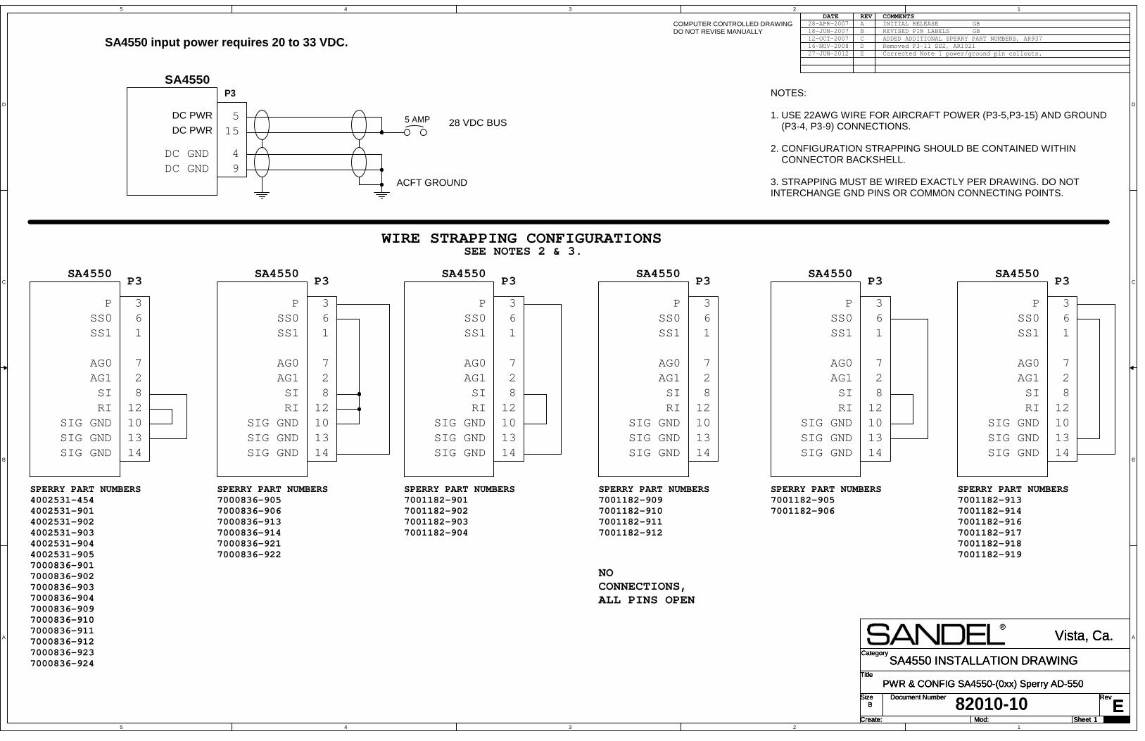
5
5
4
4
3
3
2
2
1
1
D D
C C
B B
A A
Title
Size Document Number Rev
Create: Sheet of
Category
Mod:E
PWR & CONFIG SA4550-(0xx) Sperry AD-550
Vista, Ca.
B
1 29
SA4550 INSTALLATION DRAWINGTitle
Size Document Number Rev
Create: Sheet of
Category
Mod:E
PWR & CONFIG SA4550-(0xx) Sperry AD-550
Vista, Ca.
B
1 29
SA4550 INSTALLATION DRAWINGTitle
Size Document Number Rev
Create: Sheet of
Category
Mod:E
PWR & CONFIG SA4550-(0xx) Sperry AD-550
Vista, Ca.
B
1 29
SA4550 INSTALLATION DRAWING
82010-10
DATE REV COMMENTSCOMPUTER CONTROLLED DRAWINGDO NOT REVISE MANUALLY
28-APR-2007 A INITIAL RELEASE
SA4550
SA4550 input power requires 20 to 33 VDC.
P3
28 VDC BUS
ACFT GROUND
DC PWR
94
515
DC GNDDC GND
DC PWR 5 AMP
1
2
36
7
8
1012
1314
SIG GNDSIG GNDSIG GND
P3SA4550
SPERRY PART NUMBERS7001182-9017001182-9027001182-9037001182-904
1
2
36
7
8
1012
1314
P3
SPERRY PART NUMBERS7001182-9097001182-9107001182-9117001182-912
NOCONNECTIONS,ALL PINS OPEN
1
2
36
7
8
1012
1314
P3
SPERRY PART NUMBERS7001182-9057001182-906
1
2
36
7
8
1012
1314
P3
SPERRY PART NUMBERS7001182-9137001182-9147001182-9167001182-9177001182-9187001182-919
WIRE STRAPPING CONFIGURATIONSSEE NOTES 2 & 3.
NOTES:
1. USE 22AWG WIRE FOR AIRCRAFT POWER (P3-5,P3-15) AND GROUND (P3-4, P3-9) CONNECTIONS.
2. CONFIGURATION STRAPPING SHOULD BE CONTAINED WITHIN CONNECTOR BACKSHELL.
3. STRAPPING MUST BE WIRED EXACTLY PER DRAWING. DO NOT INTERCHANGE GND PINS OR COMMON CONNECTING POINTS.
18-JUN-2007 B REVISED PIN LABELS
SS1SS0
AG0AG1
P
RISI
GBGB
SS1SS0
AG0AG1
P
RISI
SIG GNDSIG GNDSIG GND
SA4550
SS1SS0
AG0AG1
P
RISI
SIG GNDSIG GNDSIG GND
SA4550
SS1SS0
AG0AG1
P
RISI
SIG GNDSIG GNDSIG GND
SA4550
1
2
36
7
8
1012
1314
P3
SPERRY PART NUMBERS7000836-9057000836-9067000836-9137000836-9147000836-9217000836-922
SS1SS0
AG0AG1
P
RISI
SIG GNDSIG GNDSIG GND
SA4550
1
2
36
7
8
1012
1314
P3
SPERRY PART NUMBERS4002531-4544002531-9014002531-9024002531-9034002531-9044002531-9057000836-9017000836-9027000836-9037000836-9047000836-9097000836-9107000836-9117000836-9127000836-9237000836-924
SS1SS0
AG0AG1
P
RISI
SIG GNDSIG GNDSIG GND
SA4550
12-OCT-2007 C ADDED ADDITIONAL SPERRY PART NUMBERS, AR93716-NOV-2008 D Removed P3-11 SS2, AR102127-JUN-2012 E Corrected Note 1 power/ground pin callouts.
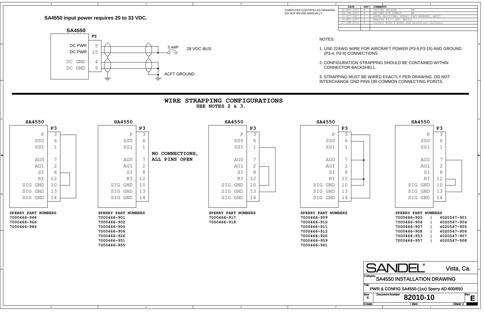
5
5
4
4
3
3
2
2
1
1
D D
C C
B B
A A
Title
Size Document Number Rev
Create: Sheet of
Category
Mod:E
PWR & CONFIG SA4550-(1xx) Sperry AD-600/650
Vista, Ca.
B
2 29
SA4550 INSTALLATION DRAWINGTitle
Size Document Number Rev
Create: Sheet of
Category
Mod:E
PWR & CONFIG SA4550-(1xx) Sperry AD-600/650
Vista, Ca.
B
2 29
SA4550 INSTALLATION DRAWINGTitle
Size Document Number Rev
Create: Sheet of
Category
Mod:E
PWR & CONFIG SA4550-(1xx) Sperry AD-600/650
Vista, Ca.
B
2 29
SA4550 INSTALLATION DRAWING
82010-10
DATE REV COMMENTSCOMPUTER CONTROLLED DRAWINGDO NOT REVISE MANUALLY
28-APR-2007 A INITIAL RELEASE
SA4550 input power requires 20 to 33 VDC.
NOTES:
1. USE 22AWG WIRE FOR AIRCRAFT POWER (P3-5,P3-15) AND GROUND (P3-4, P3-9) CONNECTIONS.
2. CONFIGURATION STRAPPING SHOULD BE CONTAINED WITHIN CONNECTOR BACKSHELL.
3. STRAPPING MUST BE WIRED EXACTLY PER DRAWING. DO NOT INTERCHANGE GND PINS OR COMMON CONNECTING POINTS.
1
2
36
7
8
1012
1314
SIG GNDSIG GNDSIG GND
P3SA4550
SPERRY PART NUMBERS7000466-9467000466-9667000466-986
1
2
36
7
8
1012
1314
P3SA4550
SPERRY PART NUMBERS7000466-9017000466-9027000466-9057000466-9067000466-9267000466-9517000466-955
NO CONNECTIONS,ALL PINS OPEN
1
2
36
7
8
1012
1314
P3SA4550
1
2
36
7
8
1012
1314
P3SA4550
WIRE STRAPPING CONFIGURATIONSSEE NOTES 2 & 3.
SPERRY PART NUMBERS7000466-9097000466-9107000466-9117000466-9127000466-9207000466-9597000466-961
SPERRY PART NUMBERS7000466-903 | 4020547-9017000466-904 | 4020547-9047000466-907 | 4020547-9057000466-908 | 4020547-9067000466-953 | 4020547-9077000466-957 | 4020547-908
1
2
36
7
8
1012
1314
P3SA4550
SPERRY PART NUMBERS7000466-9177000466-918
SA4550P3
28 VDC BUS
ACFT GROUND
DC PWR
94
515
DC GNDDC GND
DC PWR 5 AMP
18-JUN-2007 B REVISED PIN LABELS
SS1SS0
AG0AG1
P
RISI
GBGB
SS1SS0
AG0AG1
P
RISI
SIG GNDSIG GNDSIG GND
SS1SS0
AG0AG1
P
RISI
SIG GNDSIG GNDSIG GND
SS1SS0
AG0AG1
P
RISI
SIG GNDSIG GNDSIG GND
SS1SS0
AG0AG1
P
RISI
SIG GNDSIG GNDSIG GND
12-OCT-2007 C ADDED ADDITIONAL SPERRY PART NUMBERS, AR937Removed P3-11 SS2, AR1021D16-NOV-2007Correct Note 1 power and ground pin callouts.E27-JUN-2012
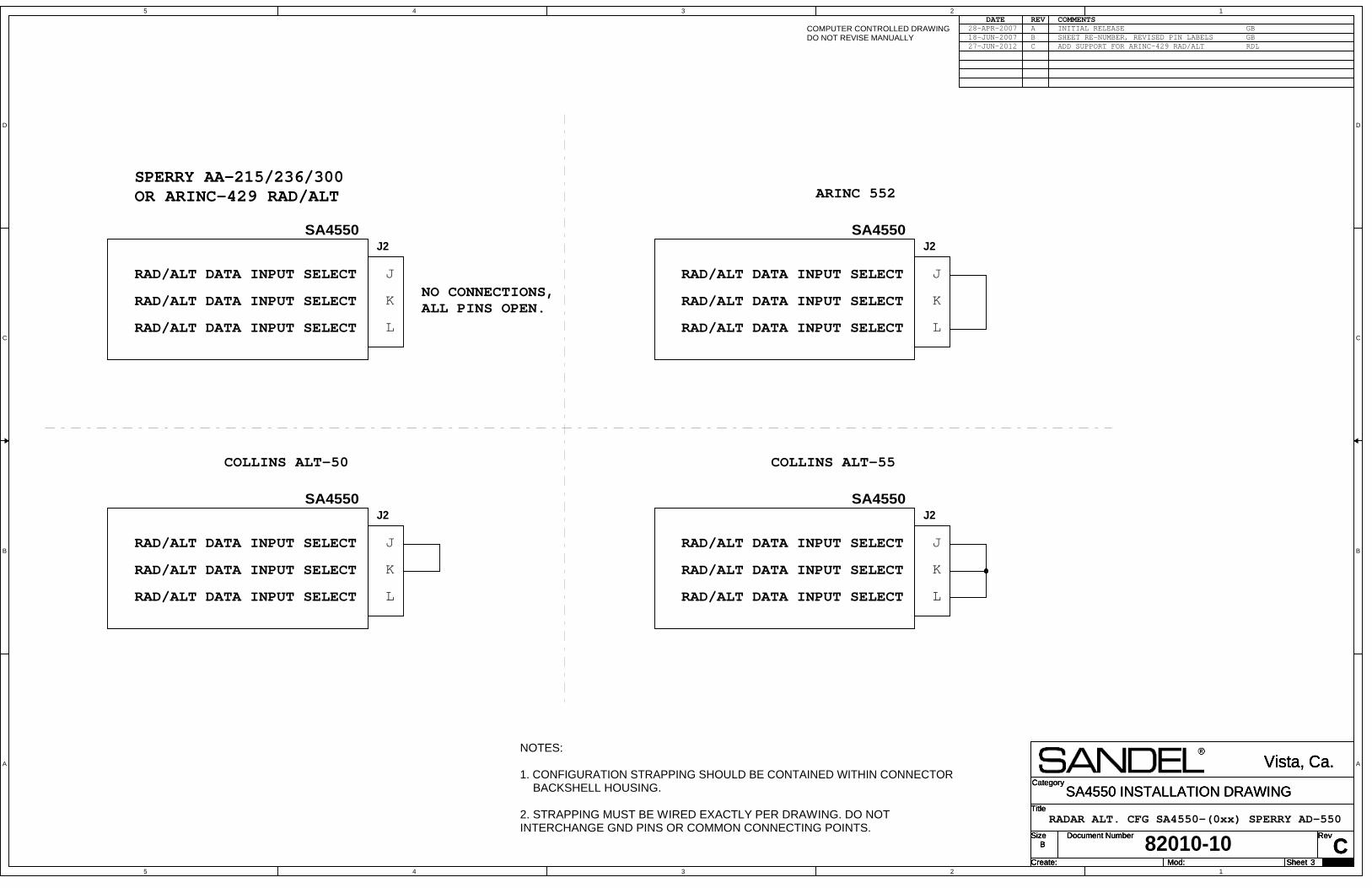
5
5
4
4
3
3
2
2
1
1
D D
C C
B B
A A
Title
Size Document Number Rev
Create: Sheet of
Category
Mod:C
Vista, Ca.
B
3 29
SA4550 INSTALLATION DRAWINGTitle
Size Document Number Rev
Create: Sheet of
Category
Mod:C
Vista, Ca.
B
3 29
SA4550 INSTALLATION DRAWINGTitle
Size Document Number Rev
Create: Sheet of
Category
Mod:C
Vista, Ca.
B
3 29
SA4550 INSTALLATION DRAWING
82010-10
DATE REV COMMENTSCOMPUTER CONTROLLED DRAWINGDO NOT REVISE MANUALLY
28-APR-2007 A INITIAL RELEASE
SA4550J2
J
K
L
SPERRY AA-215/236/300OR ARINC-429 RAD/ALT ARINC 552
COLLINS ALT-50 COLLINS ALT-55
NO CONNECTIONS,ALL PINS OPEN.
SA4550J2
J
K
L
SA4550J2
J
K
L
SA4550J2
J
K
L
RADAR ALT. CFG SA4550-(0xx) SPERRY AD-550
NOTES:
1. CONFIGURATION STRAPPING SHOULD BE CONTAINED WITHIN CONNECTOR BACKSHELL HOUSING.
2. STRAPPING MUST BE WIRED EXACTLY PER DRAWING. DO NOT INTERCHANGE GND PINS OR COMMON CONNECTING POINTS.
RAD/ALT DATA INPUT SELECT
18-JUN-2007 B
RAD/ALT DATA INPUT SELECT
RAD/ALT DATA INPUT SELECT
RAD/ALT DATA INPUT SELECT
RAD/ALT DATA INPUT SELECT
RAD/ALT DATA INPUT SELECT
RAD/ALT DATA INPUT SELECT
RAD/ALT DATA INPUT SELECT
RAD/ALT DATA INPUT SELECT
RAD/ALT DATA INPUT SELECT
RAD/ALT DATA INPUT SELECT
RAD/ALT DATA INPUT SELECT
SHEET RE-NUMBER, REVISED PIN LABELSGBGB
27-JUN-2012 C ADD SUPPORT FOR ARINC-429 RAD/ALT RDL
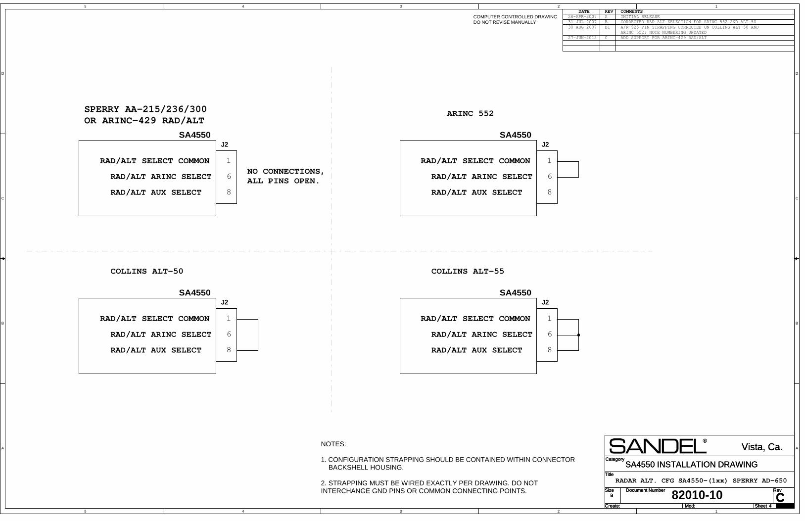
5
5
4
4
3
3
2
2
1
1
D D
C C
B B
A A
Title
Size Document Number Rev
Create: Sheet of
Category
Mod:C
Vista, Ca.
B
4 29
SA4550 INSTALLATION DRAWINGTitle
Size Document Number Rev
Create: Sheet of
Category
Mod:C
Vista, Ca.
B
4 29
SA4550 INSTALLATION DRAWINGTitle
Size Document Number Rev
Create: Sheet of
Category
Mod:C
Vista, Ca.
B
4 29
SA4550 INSTALLATION DRAWING
82010-10
DATE REV COMMENTSCOMPUTER CONTROLLED DRAWINGDO NOT REVISE MANUALLY
28-APR-2007 A INITIAL RELEASE
SA4550J2
1
6
8
RAD/ALT SELECT COMMON
SPERRY AA-215/236/300OR ARINC-429 RAD/ALT
ARINC 552
COLLINS ALT-50 COLLINS ALT-55
NO CONNECTIONS,ALL PINS OPEN.
J2
1
6
8
J2
1
6
8
J2
1
6
8
RADAR ALT. CFG SA4550-(1xx) SPERRY AD-650
NOTES:
1. CONFIGURATION STRAPPING SHOULD BE CONTAINED WITHIN CONNECTOR BACKSHELL HOUSING.
2. STRAPPING MUST BE WIRED EXACTLY PER DRAWING. DO NOT INTERCHANGE GND PINS OR COMMON CONNECTING POINTS.
SA4550
SA4550
SA4550
RAD/ALT ARINC SELECT
RAD/ALT SELECT COMMON
RAD/ALT SELECT COMMON
RAD/ALT SELECT COMMON
31-JUL-2007 B CORRECTED RAD ALT SELECTION FOR ARINC 552 AND ALT-5030-AUG-2007 B1 A/R 925 PIN STRAPPING CORRECTED ON COLLINS ALT-50 AND
ARINC 552; NOTE NUMBERING UPDATED
RAD/ALT AUX SELECT
RAD/ALT ARINC SELECT
RAD/ALT AUX SELECT
RAD/ALT ARINC SELECT
RAD/ALT AUX SELECT
RAD/ALT ARINC SELECT
RAD/ALT AUX SELECT
ADD SUPPORT FOR ARINC-429 RAD/ALTC27-JUN-2012

5
5
4
4
3
3
2
2
1
1
D D
C C
B B
A A
Title
Size Document Number Rev
Create: Sheet of
Category
Mod:B
PWR & OPTIONAL CONFIG SA4550-(0xx) Sperry HZ-454
Vista, Ca.
B
5 29
SA4550 INSTALLATION DRAWINGTitle
Size Document Number Rev
Create: Sheet of
Category
Mod:B
PWR & OPTIONAL CONFIG SA4550-(0xx) Sperry HZ-454
Vista, Ca.
B
5 29
SA4550 INSTALLATION DRAWINGTitle
Size Document Number Rev
Create: Sheet of
Category
Mod:B
PWR & OPTIONAL CONFIG SA4550-(0xx) Sperry HZ-454
Vista, Ca.
B
5 29
SA4550 INSTALLATION DRAWING
82010-10
DATE REV COMMENTSCOMPUTER CONTROLLED DRAWINGDO NOT REVISE MANUALLY
A INITIAL RELEASE, AR937
SA4550 SA4550 input power requires 20 to 33 VDC.P3
28 VDC BUS
ACFT GROUND
DC PWR
94
515
DC GNDDC GND
DC PWR 5 AMP
SEE NOTES 3, 4 & 7.
NOTES:
1. USE EXISTING AIRCRAFT WIRING FOR ALL CONNECTIONS UNLESS OTHERWISE NOTED ON THIS DRAWING.
2. USE 22AWG WIRE FOR AIRCRAFT POWER (P3-5,P3-15) AND GROUND (P3-4, P3-9) CONNECTIONS.
3. CONFIGURATION STRAPPING SHOULD BE CONTAINED WITHIN CONNECTOR BACKSHELL.
4. STRAPPING MUST BE WIRED EXACTLY PER DRAWING. DO NOT INTERCHANGE GND PINS OR COMMON CONNECTING POINTS.
5. FOR SA4550-0xx SERIAL NUMBERS 10-1028 AND BELOW J2-M MUST BE PULLED UP TO AIRCRAFT POWER IF UNUSED. IF CONNECTED EXTERNALLY THEN PULL-UP TO AIRCRAFT POWER USING 10K OHM RESISTOR.
6. OPTIONAL RADAR ALTIMETER CONNECTIONS. RETERMINATE RADAR ALTIMETER DATA FROM HZ-454 J1 PINS EE AND FF TO SA4550 J2 PINS G AND H AS SHOWN.
7. IF RADAR ALTIMETER IS NOT CONNECTED, THEN USE STANDARD CONFIGURATION STRAPPING FOUND ON 82010-IM SHEET 1.
8. ACTIVATION OF THE SA4550 MIN ANNUNCIATOR WILL BE CONTROLLED BY THE SA4550 MIN SETTING.
1
2
3
11
6
7
8
1012
1314
SPERRY HZ-454 OPTIONAL WIRINGPART NUMBERS4002531-4544002531-9014002531-9024002531-9034002531-9044002531-905
SS1SS0
SS2AG0AG1
P
RISI
SIG GNDSIG GNDSIG GND
12-OCT-2007
HZ-454
J2
J1
GH
M
EEFF
FROM RADAR ALTIMETER
Radar ALT Data (H)Radar ALT Data (C)
MIN Anunciator Input
Radar ALT (+)Radar ALT (-)
See note 5 & 8.
See note 6.
B CORRECT POWER AND GROUND PIN CALLOUTS IN NOTE 2.27-JUN-2012
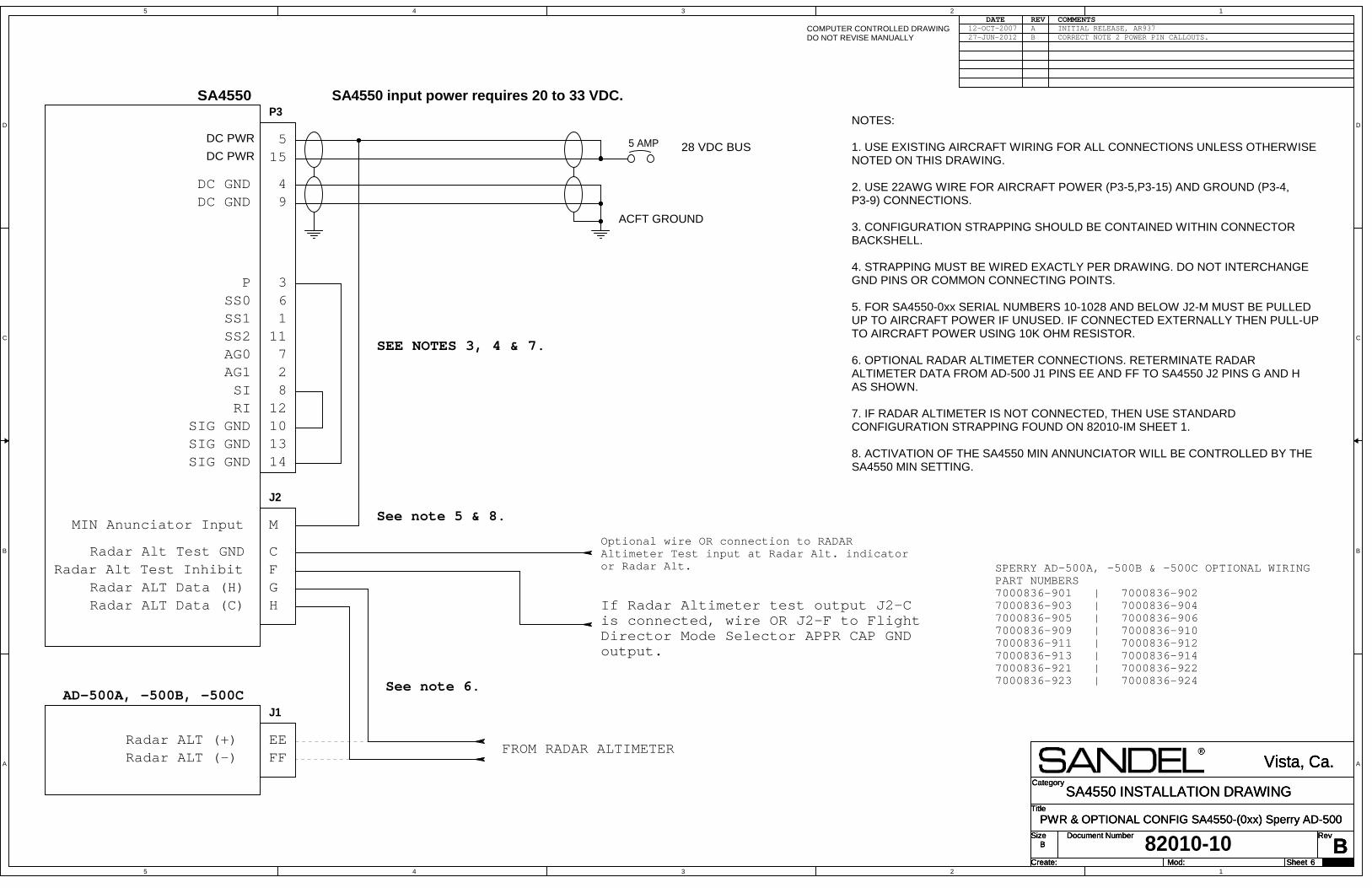
5
5
4
4
3
3
2
2
1
1
D D
C C
B B
A A
Title
Size Document Number Rev
Create: Sheet of
Category
Mod:B
PWR & OPTIONAL CONFIG SA4550-(0xx) Sperry AD-500
Vista, Ca.
B
6 29
SA4550 INSTALLATION DRAWINGTitle
Size Document Number Rev
Create: Sheet of
Category
Mod:B
PWR & OPTIONAL CONFIG SA4550-(0xx) Sperry AD-500
Vista, Ca.
B
6 29
SA4550 INSTALLATION DRAWINGTitle
Size Document Number Rev
Create: Sheet of
Category
Mod:B
PWR & OPTIONAL CONFIG SA4550-(0xx) Sperry AD-500
Vista, Ca.
B
6 29
SA4550 INSTALLATION DRAWING
82010-10
DATE REV COMMENTSCOMPUTER CONTROLLED DRAWINGDO NOT REVISE MANUALLY
A INITIAL RELEASE, AR937
SA4550 SA4550 input power requires 20 to 33 VDC.P3
28 VDC BUS
ACFT GROUND
DC PWR
94
515
DC GNDDC GND
DC PWR 5 AMP
SEE NOTES 3, 4 & 7.
NOTES:
1. USE EXISTING AIRCRAFT WIRING FOR ALL CONNECTIONS UNLESS OTHERWISE NOTED ON THIS DRAWING.
2. USE 22AWG WIRE FOR AIRCRAFT POWER (P3-5,P3-15) AND GROUND (P3-4, P3-9) CONNECTIONS.
3. CONFIGURATION STRAPPING SHOULD BE CONTAINED WITHIN CONNECTOR BACKSHELL.
4. STRAPPING MUST BE WIRED EXACTLY PER DRAWING. DO NOT INTERCHANGE GND PINS OR COMMON CONNECTING POINTS.
5. FOR SA4550-0xx SERIAL NUMBERS 10-1028 AND BELOW J2-M MUST BE PULLED UP TO AIRCRAFT POWER IF UNUSED. IF CONNECTED EXTERNALLY THEN PULL-UP TO AIRCRAFT POWER USING 10K OHM RESISTOR.
6. OPTIONAL RADAR ALTIMETER CONNECTIONS. RETERMINATE RADAR ALTIMETER DATA FROM AD-500 J1 PINS EE AND FF TO SA4550 J2 PINS G AND H AS SHOWN.
7. IF RADAR ALTIMETER IS NOT CONNECTED, THEN USE STANDARD CONFIGURATION STRAPPING FOUND ON 82010-IM SHEET 1.
8. ACTIVATION OF THE SA4550 MIN ANNUNCIATOR WILL BE CONTROLLED BY THE SA4550 MIN SETTING.
1
2
3
11
6
7
8
1012
1314
SPERRY AD-500A, -500B & -500C OPTIONAL WIRINGPART NUMBERS7000836-901 | 7000836-9027000836-903 | 7000836-9047000836-905 | 7000836-9067000836-909 | 7000836-9107000836-911 | 7000836-9127000836-913 | 7000836-9147000836-921 | 7000836-9227000836-923 | 7000836-924
SS1SS0
SS2AG0AG1
P
RISI
SIG GNDSIG GNDSIG GND
12-OCT-2007
AD-500A, -500B, -500C
J2
J1
GH
M
EEFF
FROM RADAR ALTIMETER
Radar ALT Data (H)Radar ALT Data (C)
MIN Anunciator Input
Radar ALT (+)Radar ALT (-)
See note 5 & 8.
See note 6.
CF
Radar Alt Test GNDRadar Alt Test Inhibit
Optional wire OR connection to RADARAltimeter Test input at Radar Alt. indicatoror Radar Alt.
If Radar Altimeter test output J2-Cis connected, wire OR J2-F to FlightDirector Mode Selector APPR CAP GNDoutput.
B CORRECT NOTE 2 POWER PIN CALLOUTS.27-JUN-2012

5
5
4
4
3
3
2
2
1
1
D D
C C
B B
A A
Title
Size Document Number Rev
Create: Sheet of
Category
Mod:C
Vista, Ca.
B
7 29
SA4550 INSTALLATION DRAWINGTitle
Size Document Number Rev
Create: Sheet of
Category
Mod:C
Vista, Ca.
B
7 29
SA4550 INSTALLATION DRAWINGTitle
Size Document Number Rev
Create: Sheet of
Category
Mod:C
Vista, Ca.
B
7 29
SA4550 INSTALLATION DRAWING
82010-10
DATE REV COMMENTSCOMPUTER CONTROLLED DRAWINGDO NOT REVISE MANUALLY
28-FEB-2008 A INITIAL RELEASE
SA4550 input power requires 20 to 33 VDC.
P3
28 VDC BUS
ACFT GROUND
DC PWR
9
4
5
15
DC GND
DC GND
DC PWR 5 AMP
SA4550 CONNECTOR P3 WIRE STRAPPING CONFIGURATIONSSEE NOTES 2 & 3.
NOTES:
1. USE 22AWG WIRE FOR AIRCRAFT POWER (P3-5,P3-15) AND GROUND (P3-4, P3-9) CONNECTIONS.
2. CONFIGURATION STRAPPING SHOULD BE CONTAINED WITHIN CONNECTOR BACKSHELL.
3. STRAPPING MUST BE WIRED EXACTLY PER DRAWING. DO NOT INTERCHANGE GND PINS OR COMMON CONNECTING POINTS.
2
3
7
8
10
12
13
14
P3
RS0
RS1
P
RI
SI
SIG GND
SIG GND
SIG GND
PWR & CONFIG SA4550-((4,5,6)xx) Collins ADI84/84A/84C & 329B-7R/7R1/7R2/7R3/7R4/7R5
Sperry AA-215/236/300or ARINC-429 Radar AltitudeSpeed Indicator EnabledDefault no strapping
Sperry AA-215/236/300or ARINC-429 Radar AltitudeSpeed Indicator Disabled
ARINC 552Speed Indicator Enabled
ARINC 552Speed Indicator Disabled
Collins ALT-50Speed Indicator Enabled
Collins ALT-50Speed Indicator Disabled
Collins ALT-55Speed Indicator Enabled
Collins ALT-55Speed Indicator Disabled
RADAR ALT Display DisabledSpeed Indicator Enabled
RADAR ALT Display DisableSpeed Indicator Disabled
2
3
7
8
10
12
13
14
P3
RS0
RS1
P
RI
SI
SIG GND
SIG GND
SIG GND
2
3
7
8
10
12
13
14
P3
RS0
RS1
P
RI
SI
SIG GND
SIG GND
SIG GND
2
3
7
8
10
12
13
14
P3
RS0
RS1
P
RI
SI
SIG GND
SIG GND
SIG GND
2
3
7
8
10
12
13
14
P3
RS0
RS1
P
RI
SI
SIG GND
SIG GND
SIG GND
2
3
7
8
10
12
13
14
P3
RS0
RS1
P
RI
SI
SIG GND
SIG GND
SIG GND
2
3
7
8
10
12
13
14
P3
RS0
RS1
P
RI
SI
SIG GND
SIG GND
SIG GND
2
3
7
8
10
12
13
14
P3
RS0
RS1
P
RI
SI
SIG GND
SIG GND
SIG GND
2
3
7
8
10
12
13
14
P3
RS0
RS1
P
RI
SI
SIG GND
SIG GND
SIG GND
2
3
7
8
10
12
13
14
P3
RS0
RS1
P
RI
SI
SIG GND
SIG GND
SIG GND
18-JUL-2008 B Corrected RADALT strapping. AR102127-JUN-2012 C Corrected Note 1 Power and Ground pin callouts. Add
ARINC-429 strapping options.
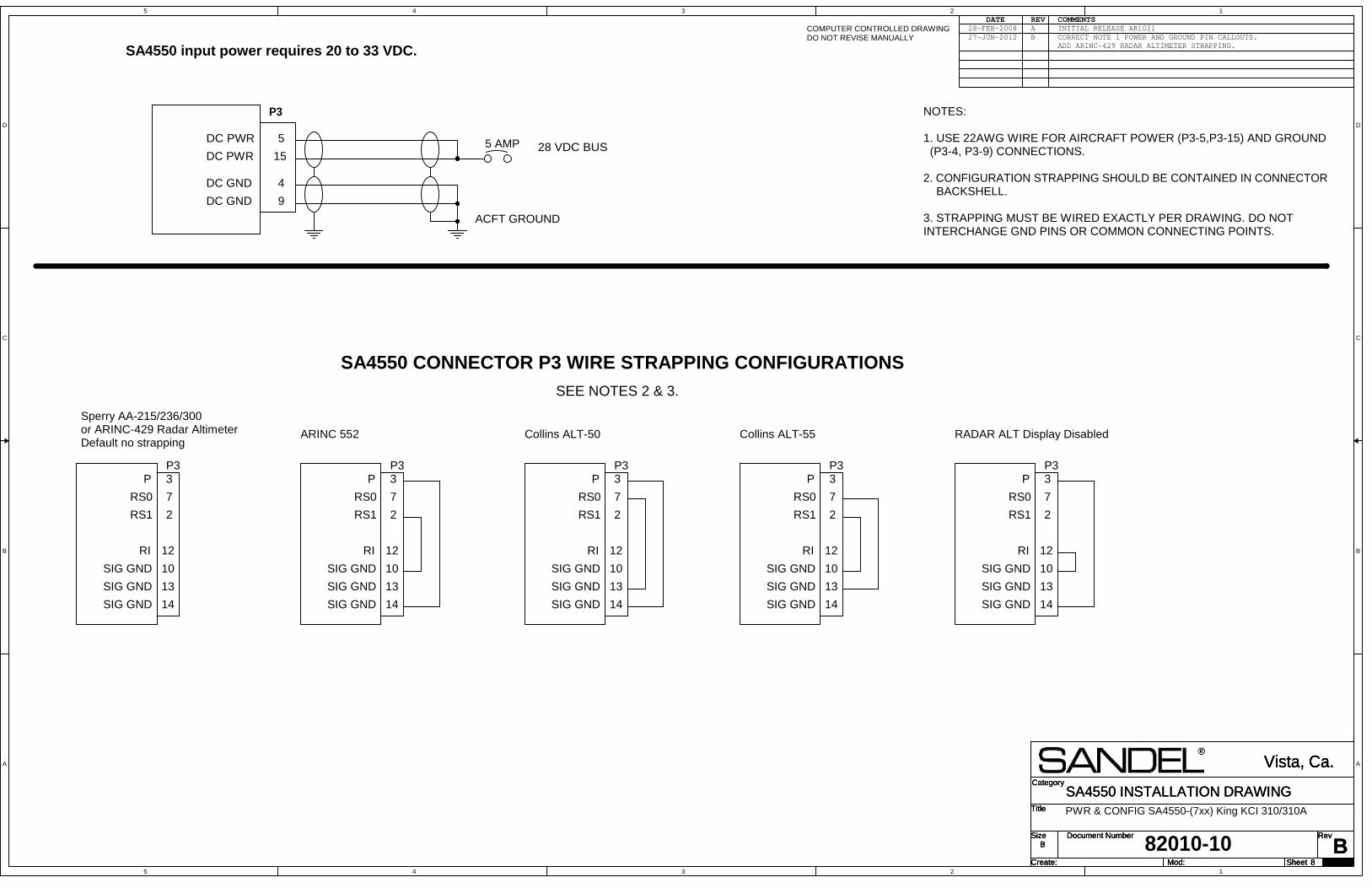
5
5
4
4
3
3
2
2
1
1
D D
C C
B B
A A
Title
Size Document Number Rev
Create: Sheet of
Category
Mod:B
Vista, Ca.
B
8 29
SA4550 INSTALLATION DRAWINGTitle
Size Document Number Rev
Create: Sheet of
Category
Mod:B
Vista, Ca.
B
8 29
SA4550 INSTALLATION DRAWINGTitle
Size Document Number Rev
Create: Sheet of
Category
Mod:B
Vista, Ca.
B
8 29
SA4550 INSTALLATION DRAWING
82010-10
DATE REV COMMENTSCOMPUTER CONTROLLED DRAWINGDO NOT REVISE MANUALLY
28-FEB-2008 A INITIAL RELEASE AR1021
SA4550 input power requires 20 to 33 VDC.
P3
28 VDC BUS
ACFT GROUND
DC PWR
9
4
5
15
DC GND
DC GND
DC PWR 5 AMP
SA4550 CONNECTOR P3 WIRE STRAPPING CONFIGURATIONSSEE NOTES 2 & 3.
NOTES:
1. USE 22AWG WIRE FOR AIRCRAFT POWER (P3-5,P3-15) AND GROUND (P3-4, P3-9) CONNECTIONS.
2. CONFIGURATION STRAPPING SHOULD BE CONTAINED IN CONNECTOR BACKSHELL.
3. STRAPPING MUST BE WIRED EXACTLY PER DRAWING. DO NOT INTERCHANGE GND PINS OR COMMON CONNECTING POINTS.
2
3
7
10
12
13
14
P3
RS0
RS1
P
RI
SIG GND
SIG GND
SIG GND
PWR & CONFIG SA4550-(7xx) King KCI 310/310A
Sperry AA-215/236/300or ARINC-429 Radar AltimeterDefault no strapping
ARINC 552 Collins ALT-50 Collins ALT-55 RADAR ALT Display Disabled
2
3
7
10
12
13
14
P3
RS0
RS1
P
RI
SIG GND
SIG GND
SIG GND
2
3
7
10
12
13
14
P3
RS0
RS1
P
RI
SIG GND
SIG GND
SIG GND
2
3
7
10
12
13
14
P3
RS0
RS1
P
RI
SIG GND
SIG GND
SIG GND
2
3
7
10
12
13
14
P3
RS0
RS1
P
RI
SIG GND
SIG GND
SIG GND
27-JUN-2012 B CORRECT NOTE 1 POWER AND GROUND PIN CALLOUTS. ADD ARINC-429 RADAR ALTIMETER STRAPPING.
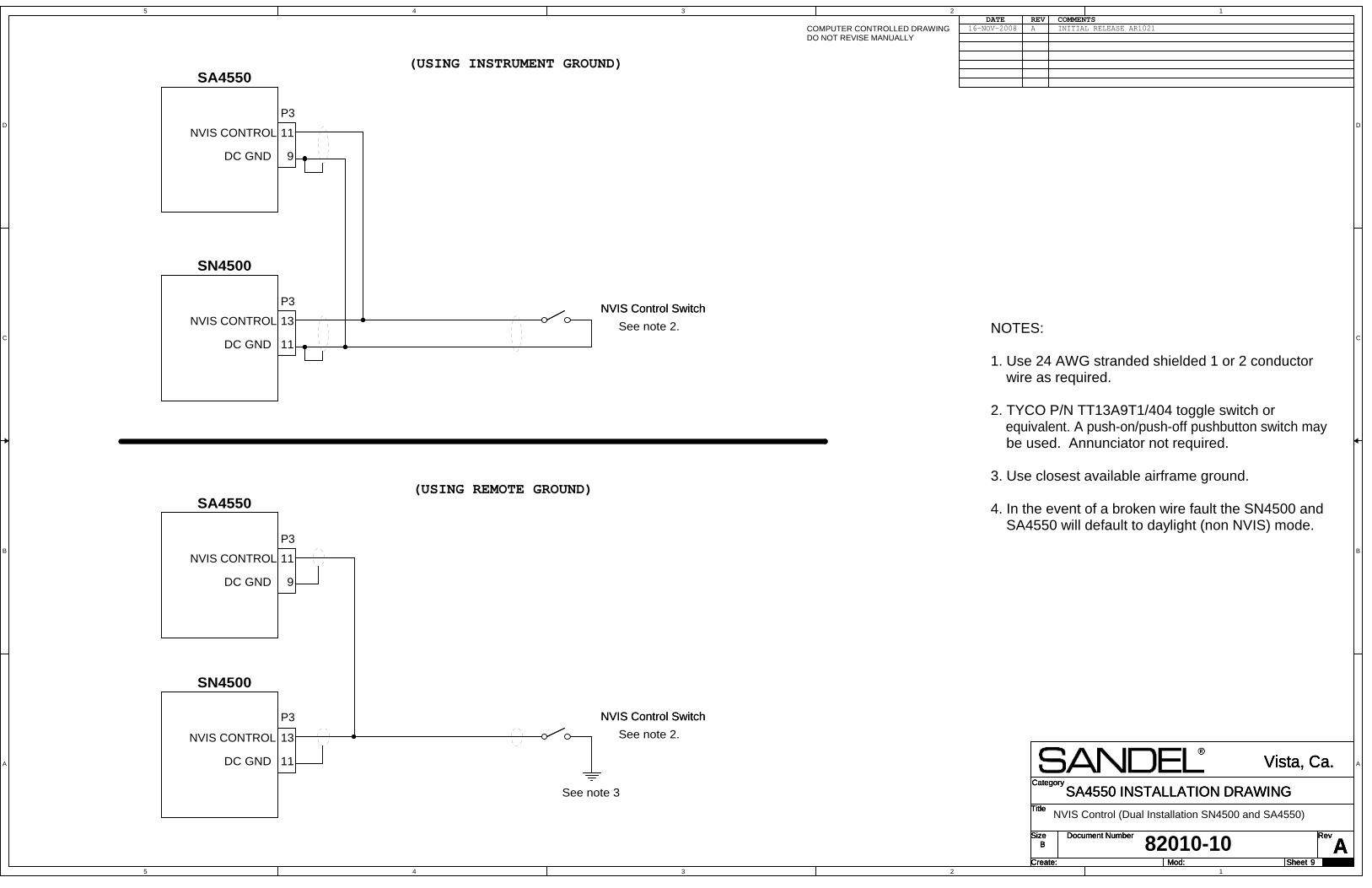
5
5
4
4
3
3
2
2
1
1
D D
C C
B B
A A
Title
Size Document Number Rev
Create: Sheet of
Category
Mod:A
Vista, Ca.
B
9 29
SA4550 INSTALLATION DRAWINGTitle
Size Document Number Rev
Create: Sheet of
Category
Mod:A
Vista, Ca.
B
9 29
SA4550 INSTALLATION DRAWINGTitle
Size Document Number Rev
Create: Sheet of
Category
Mod:A
Vista, Ca.
B
9 29
SA4550 INSTALLATION DRAWING
82010-10
DATE REV COMMENTSCOMPUTER CONTROLLED DRAWINGDO NOT REVISE MANUALLY
16-NOV-2008 A INITIAL RELEASE AR1021
NVIS Control (Dual Installation SN4500 and SA4550)
13
11
See note 2.
(USING REMOTE GROUND)
(USING INSTRUMENT GROUND)
See note 3
NVIS CONTROL
SN4500
P3
See note 2.NVIS CONTROL
SN4500
P3
13
11
11
9
DC GND
NVIS CONTROL
SA4550
P3
11
9
NVIS CONTROL
SA4550
P3
DC GND
DC GND
DC GND
NOTES:
1. Use 24 AWG stranded shielded 1 or 2 conductor wire as required.
2. TYCO P/N TT13A9T1/404 toggle switch or equivalent. A push-on/push-off pushbutton switch may be used. Annunciator not required.
3. Use closest available airframe ground.
4. In the event of a broken wire fault the SN4500 and SA4550 will default to daylight (non NVIS) mode.
NVIS Control SwitchNVIS Control Switch
NVIS Control SwitchNVIS Control Switch
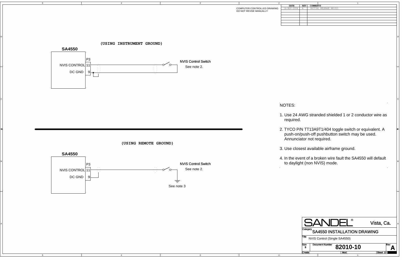
5
5
4
4
3
3
2
2
1
1
D D
C C
B B
A A
Title
Size Document Number Rev
Create: Sheet of
Category
Mod:A
Vista, Ca.
B
10 29
SA4550 INSTALLATION DRAWINGTitle
Size Document Number Rev
Create: Sheet of
Category
Mod:A
Vista, Ca.
B
10 29
SA4550 INSTALLATION DRAWINGTitle
Size Document Number Rev
Create: Sheet of
Category
Mod:A
Vista, Ca.
B
10 29
SA4550 INSTALLATION DRAWING
82010-10
DATE REV COMMENTSCOMPUTER CONTROLLED DRAWINGDO NOT REVISE MANUALLY
16-NOV-2008 A INITIAL RELEASE AR1021
NVIS Control (Single SA4550)
See note 2.
(USING REMOTE GROUND)
(USING INSTRUMENT GROUND)
See note 3
See note 2.
9
NOTES:
1. Use 24 AWG stranded shielded 1 or 2 conductor wire as required.
2. TYCO P/N TT13A9T1/404 toggle switch or equivalent. A push-on/push-off pushbutton switch may be used. Annunciator not required.
3. Use closest available airframe ground.
4. In the event of a broken wire fault the SA4550 will default to daylight (non NVIS) mode.
11NVIS CONTROL
SA4550
P3
DC GND
11
9
NVIS CONTROL
SA4550
P3
DC GND
NVIS Control SwitchNVIS Control Switch
NVIS Control SwitchNVIS Control Switch
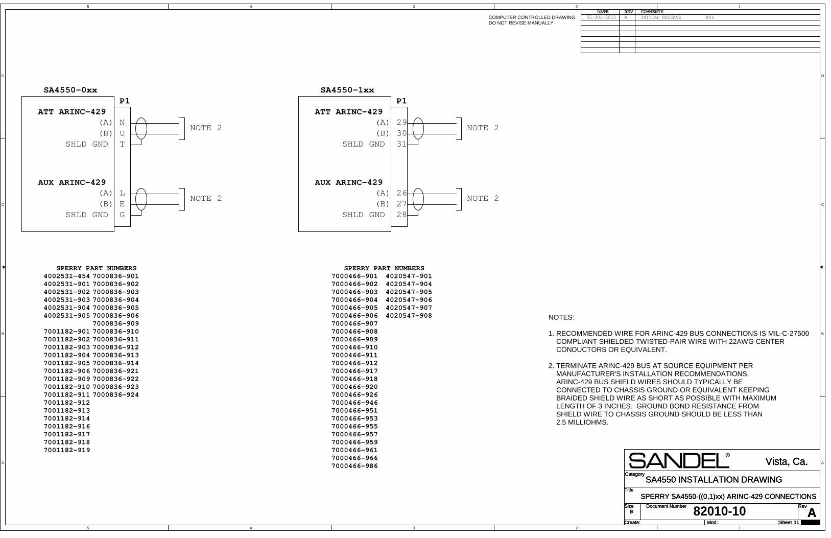
5
5
4
4
3
3
2
2
1
1
D D
C C
B B
A A
Title
Size Document Number Rev
Create: Sheet of
Category
Mod:A
SPERRY SA4550-((0,1)xx) ARINC-429 CONNECTIONS
Vista, Ca.
B
11 29
SA4550 INSTALLATION DRAWINGTitle
Size Document Number Rev
Create: Sheet of
Category
Mod:A
SPERRY SA4550-((0,1)xx) ARINC-429 CONNECTIONS
Vista, Ca.
B
11 29
SA4550 INSTALLATION DRAWINGTitle
Size Document Number Rev
Create: Sheet of
Category
Mod:A
SPERRY SA4550-((0,1)xx) ARINC-429 CONNECTIONS
Vista, Ca.
B
11 29
SA4550 INSTALLATION DRAWING
82010-10
DATE REV COMMENTSCOMPUTER CONTROLLED DRAWINGDO NOT REVISE MANUALLY
02-JUL-2012 A INITIAL RELEASE
NOTES:
1. RECOMMENDED WIRE FOR ARINC-429 BUS CONNECTIONS IS MIL-C-27500 COMPLIANT SHIELDED TWISTED-PAIR WIRE WITH 22AWG CENTER CONDUCTORS OR EQUIVALENT.
2. TERMINATE ARINC-429 BUS AT SOURCE EQUIPMENT PER MANUFACTURER'S INSTALLATION RECOMMENDATIONS. ARINC-429 BUS SHIELD WIRES SHOULD TYPICALLY BE CONNECTED TO CHASSIS GROUND OR EQUIVALENT KEEPING BRAIDED SHIELD WIRE AS SHORT AS POSSIBLE WITH MAXIMUM LENGTH OF 3 INCHES. GROUND BOND RESISTANCE FROM SHIELD WIRE TO CHASSIS GROUND SHOULD BE LESS THAN 2.5 MILLIOHMS.
RDL
T
NU
LEG
P1
SPERRY PART NUMBERS4002531-4544002531-9014002531-9024002531-9034002531-9044002531-905
7001182-9017001182-9027001182-9037001182-9047001182-9057001182-9067001182-9097001182-9107001182-9117001182-9127001182-9137001182-9147001182-9167001182-9177001182-9187001182-919
SHLD GND(B)(A)
AUX ARINC-429
SA4550-0xx
7000836-9017000836-9027000836-9037000836-9047000836-9057000836-9067000836-9097000836-9107000836-9117000836-9127000836-9137000836-9147000836-9217000836-9227000836-9237000836-924
ATT ARINC-429
SHLD GND(B)(A)
NOTE 2
NOTE 2
4020547-9014020547-9044020547-9054020547-9064020547-9074020547-908
SPERRY PART NUMBERS7000466-9017000466-9027000466-9037000466-9047000466-9057000466-9067000466-9077000466-9087000466-9097000466-9107000466-9117000466-9127000466-9177000466-9187000466-9207000466-9267000466-9467000466-9517000466-9537000466-9557000466-9577000466-9597000466-9617000466-9667000466-986
ATT ARINC-429
SHLD GND(B)(A)
NOTE 2
NOTE 2
31
2930
262728
P1
SHLD GND(B)(A)
AUX ARINC-429
SA4550-1xx

5
5
4
4
3
3
2
2
1
1
D D
C C
B B
A A
Title
Size Document Number Rev
Create: Sheet of
Category
Mod:A
SA4550-((4,5,6,7)xx) ARINC-429 CONNECTIONS
Vista, Ca.
B
12 29
SA4550 INSTALLATION DRAWINGTitle
Size Document Number Rev
Create: Sheet of
Category
Mod:A
SA4550-((4,5,6,7)xx) ARINC-429 CONNECTIONS
Vista, Ca.
B
12 29
SA4550 INSTALLATION DRAWINGTitle
Size Document Number Rev
Create: Sheet of
Category
Mod:A
SA4550-((4,5,6,7)xx) ARINC-429 CONNECTIONS
Vista, Ca.
B
12 29
SA4550 INSTALLATION DRAWING
82010-10
DATE REV COMMENTSCOMPUTER CONTROLLED DRAWINGDO NOT REVISE MANUALLY
02-JUL-2012 A INITIAL RELEASE
NOTES:
1. RECOMMENDED WIRE FOR ARINC-429 BUS CONNECTIONS IS MIL-C-27500 COMPLIANT SHIELDED TWISTED-PAIR WIRE WITH 22AWG CENTER CONDUCTORS OR EQUIVALENT.
2. TERMINATE ARINC-429 BUS AT SOURCE EQUIPMENT PER MANUFACTURER'S INSTALLATION RECOMMENDATIONS. ARINC-429 BUS SHIELD WIRES SHOULD TYPICALLY BE CONNECTED TO CHASSIS GROUND OR EQUIVALENT KEEPING BRAIDED SHIELD WIRE AS SHORT AS POSSIBLE WITH MAXIMUM LENGTH OF 3 INCHES. GROUND BOND RESISTANCE FROM SHIELD WIRE TO CHASSIS GROUND SHOULD BE LESS THAN 2.5 MILLIOHMS.
RDL
C
AB
LMN
P1
SHLD GND(B)(A)
AUX ARINC-429
SA4550-(4,5,6)xx
ATT ARINC-429
SHLD GND(B)(A)
NOTE 2
NOTE 2
ATT ARINC-429
SHLD GND(B)(A)
NOTE 2
NOTE 2
f
de
ghi
P1
SHLD GND(B)(A)
AUX ARINC-429
SA4550-7xx
COLLINS ADI-84ADI-84C329B-7Rx
BENDIX/KINGKCI-310/310A