Embed Size (px)
Citation preview

8.1m Ka-Band Earth Station
Antenna
Assembly, Installation, Operations, &
Maintenance Manual
Document# OM81KAA – Revision J
ASC Signal Corporation
CANADA: USA:
606 Beech Street 1120 Jupiter Rd.
Whitby, Ontario, Canada Ste. 102
L1N 7T8 Plano, TX 75074

OM81KAA_Rev J Page 1 of 25
© 2013-14 ASC Signal Corporation All Rights Reserved. No part of this document may be photocopied, reproduced, stored in a retrieval system, or transmitted, in any form or by any means whether electronic, mechanical, or otherwise without the prior written permission of ASC Signal Corporation. ASC Signal Corporation reserves the right to change details in this publication without notice. Trademark Notices Any and all products and companies named herein are the trademarks of their respective creators and/or owners. Open Source Software Notice This product makes extensive use of Open Source Software (OSS), including but not limited to the operating system, network agents, user interface shells, and tools used to develop the software. This software gives you, the customer, the benefit of a large base of well-tested and feature-rich system software while lowering the expense of providing these features to you. It also carries certain obligations. Some of this software is licensed by the GNU General Public License (GPL), which requires that all modifications or additions to the source code be kept public, and that the licensee continues to make the source code covered public. None of this source code has been modified for use in this product. If you are a user of this product who desires a copy of any source code covered by the GPL, contact our technical support and we will provide this free of charge through an agreeable medium. We expect all source code archives will be posted to public FTP servers. At the time of this writing the exact address is not known. Be advised that this is a large archive. We may recommend you obtain it from the source we obtained it from, as the source may be using more recent versions. We will always supply it ourselves if you prefer. Some of this software is licensed by the GNU Lesser General Public License (LGPL), which requires that modifications be kept public but does not require proprietary source code linked to LGPL'ed libraries be made public. None of this code has been modified for use in this product. All of the required source code will be conveyed along with the code covered by the GPL above. Some of this software is licensed by variations of the Berkeley Software Distribution (BSD) license, which do not require us to pass on source code. Some of this software has been modified for use in this product. However, in the spirit of open source, the original code will be supplied in the same manner as the code covered by the GPL on request. Please be advised that you will incur the same responsibilities we have incurred if you choose to redistribute any or all of the source codes obtained through this method. Please read the included license documents carefully. If you have any questions about our interpretation of our obligations under OSS licenses, do not hesitate to contact us. Our intent is to comply fully with all licensing obligations.
©ASC Signal Corporation www.ascsignal.com
OM81KAA_Rev J Page 2 of 25
Table of Contents
INTRODUCTION: How to Use This Manual 4 I.I Purpose & Overview 4
I.II Description 4
I.III Miscellaneous Notices 5
I.IV Warning Symbols 5
I.V Safety Terms Summary 5
I.VI Summary of Safety Precautions 6
I.VII Things to Never Do 7
I.VIII Parts Verification 7
1.0 Recommended Tools & Foundation Preparation 8 1.1 Recommended Tools 8
1.2 A-325 Tensioning Procedure 9
1.3 Foundation Preparation 10
1.4 8.1m Assembly & Installation Reference Drawings 10
2.0 Mount & Antenna Assembly Procedures 11 2.1 Assembly Sequence & Helpful Tips 11 2.2 General Subreflector Alignment Guidelines 12
3.0 Operation 13 3.1 Acquiring Satellites 13 3.2 Subreflector Adjustment 16
4.0 Preventive Maintenance 17 4.1 General Cleaning 17
4.1.1 Electrical Parts 17 4.1.2 Mechanical parts 17
4.2 Inspections 17 4.2.1 Local Control/Motor Drive Controller Inspection 18 4.2.2 Antenna Inspection 18 4.2.3 Drive System Voltage & Current Checks 19
4.3 Preservation & Lubrication of Component Parts 19
4.3.1 Preservation of Aluminum Parts 19
4.3.2 Preservation of Galvanized Surfaces 20 4.3.3 Lubrication 20
4.3.4 Lubrication of Jackscrews/Motors 20
4.3.5 Lubrication of Gear Motor/Housing Fill Drain Requirements 20
4.4 Site Acceptance Test Procedure 21
5.0 Corrective Maintenance & Troubleshooting 22 5.1 Top 5 ESA Maintenance & Troubleshooting FAQ 22 5.2 Corrective Painting Instructions 22
5.2.1 Preparatory Cleaning of Aluminum Surfaces 22 5.2.2 Priming Cleaned Aluminum Surfaces 22 5.2.3 Painting Primed Aluminum Surfaces 23 5.2.4 Prepping & Painting Galvanized Surfaces 23 5.2.5 Priming & Painting Cleaned Jack Surfaces 23
5.3 Removing Backlash via Jack Adjustment 23 5.4 Maintenance Kits 24
OM81KAA_Rev J Page 3 of 25
APPENDIX: Equipment Issues & Technical Support 25
List of Figures Figure 1-1a: Bolts Shorter than 4 Diameters 9
Figure 1-1b: Bolts Longer than 4 Diameters 9
Figure 1-2: Scraping Foundation Pads 10
Figure 3-1: Pure Noise Signal on Spectrum Analyzer 13 Figure 3-2: Minimum Transponder Signal on Spectrum Analyzer 13 Figure 3-3: Antenna Radiation Pattern Topographical Diagram w/ Plan View 14 Figure 3-4: Polarization at 45 Degrees from Optimum Setting 15 Figure 3-5: Maximizing Odd Transponders 15 Figure 3-6: Optimum Polarization Settings 15
Figure 4-1: High-Speed Antenna Lubrication Points 21
Figure 5-1: Jac/Jack Anti-Backlash Procedure 24
List of Tables Table 1.1: Recommended Tools 8
Table 1.2: 7.6m Assembly & Installation Drawings 10
Table 4.1: Lubrication Chart 21
Table 5.1: Cure Times 23
Table 5.2: Maintenance Kits 24
OM81KAA_Rev J Page 4 of 25
INTRODUCTION: How to Use This Manual
I.I Purpose & Overview
PURPOSE The scope of this manual is intended to provide station personnel with the base installation, operation, and maintenance requirements necessary for an 8.1-Meter C-, X- or Ku/K-Band Earth Station Antenna. This manual provides a convenient reference for authorized operator/service personnel requiring technical information on general system or specific subsystem equipment.
Top Level Assembly Numbers are as follows: 8.1m Ka-Band ESA: ESB1KAA-1
‐ ‐ ‐ ‐ ‐ ‐ ‐ ‐ ‐ ‐ ‐ ‐ ‐ ‐ OVERVIEW The installation, operation, and maintenance of the 8.1m Ka-Band Earth Station Antenna require qualified and experienced personnel. ASC Signal installation, operation, and maintenance instructions are illustrated for such personnel. Additionally, the antenna should be inspected by qualified personnel to verify proper installation, maintenance, and condition of equipment as described in Preventive Maintenance. The basic equipment and accessories are either manufactured or design controlled by ASC Signal Corporation.
The prerequisite information necessary for the 8.1m Ka-Band Earth Station Antenna can be found in this section. Furthermore, this section should be reviewed before performing the installation, operation, or maintenance. Warnings, recommended tools, and the antenna parts can be verified and/or determined with such a review.
I.II Description
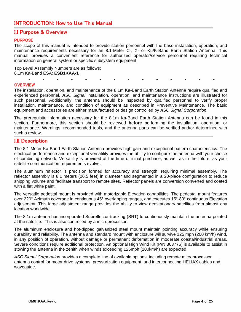
The 8.1-Meter Ka-Band Earth Station Antenna provides high gain and exceptional pattern characteristics. The electrical performance and exceptional versatility provides the ability to configure the antenna with your choice of combining network. Versatility is provided at the time of initial purchase, as well as in the future, as your satellite communication requirements evolve.
The aluminum reflector is precision formed for accuracy and strength, requiring minimal assembly. The reflector assembly is 8.1 meters (26.5 feet) in diameter and segmented in a 20-piece configuration to reduce shipping volume and facilitate transport to remote sites. Reflector panels are conversion converted and coated with a flat white paint.
The versatile pedestal mount is provided with motorizable Elevation capabilities. The pedestal mount features over 220° Azimuth coverage in continuous 45° overlapping ranges, and executes 15°-80° continuous Elevation adjustment. This large adjustment range provides the ability to view geostationary satellites from almost any location worldwide.
The 8.1m antenna has incorporated Subreflector tracking (SRT) to continuously maintain the antenna pointed at the satellite. This is also controlled by a microprocessor.
The aluminum enclosure and hot-dipped galvanized steel mount maintain pointing accuracy while ensuring durability and reliability. The antenna and standard mount with enclosure will survive 125 mph (200 km/h) wind, in any position of operation, without damage or permanent deformation in moderate coastal/industrial areas. Severe conditions require additional protection. An optional High Wind Kit (P/N 303776) is available to assist in stowing the antenna in the zenith when winds exceeding 125mph (200km/h) are expected.
ASC Signal Corporation provides a complete line of available options, including remote microprocessor antenna control for motor drive systems, pressurization equipment, and interconnecting HELIAX cables and waveguide.
OM81KAA_Rev J Page 5 of 25
I.III Miscellaneous Notices
Proprietary Information The technical data contained herein is proprietary to ASC Signal Corporation. It is intended for use in the installation, operation, and maintenance of ASC Signal equipment. This data shall not be disclosed or duplicated, in whole or in part, without the expressed written consent of ASC Signal Corporation.
‐ ‐ ‐ ‐ ‐ ‐ ‐ ‐ ‐ ‐ ‐ ‐ ‐ ‐ Installation Notice Installation, maintenance, or removal of the hardware described in this manual requires qualified and experienced personnel. ASC Signal installation instructions are written for such personnel. Qualified personnel MUST perform proper installation and maintenance of the equipment, and MUST verify the condition of the equipment at initial installation and periodically thereafter. NOTE: ASC Signal is NOT liable or responsible for results of improper or unsafe installation and maintenance practices. All designs, specifications, and availability of products are subject to change without notice.
‐ ‐ ‐ ‐ ‐ ‐ ‐ ‐ ‐ ‐ ‐ ‐ ‐ ‐ IMPORTANT: What to Know When You See OPTION: Any time you see OPTION: this means that the information following it is related to an optional element (in either hardware or software) that may or may not apply to the arrangement of your particular NGC Unit. Please note that if you see an option that you do not have but would like to purchase, please contact ASC Signal.
I.IV Warning Symbols
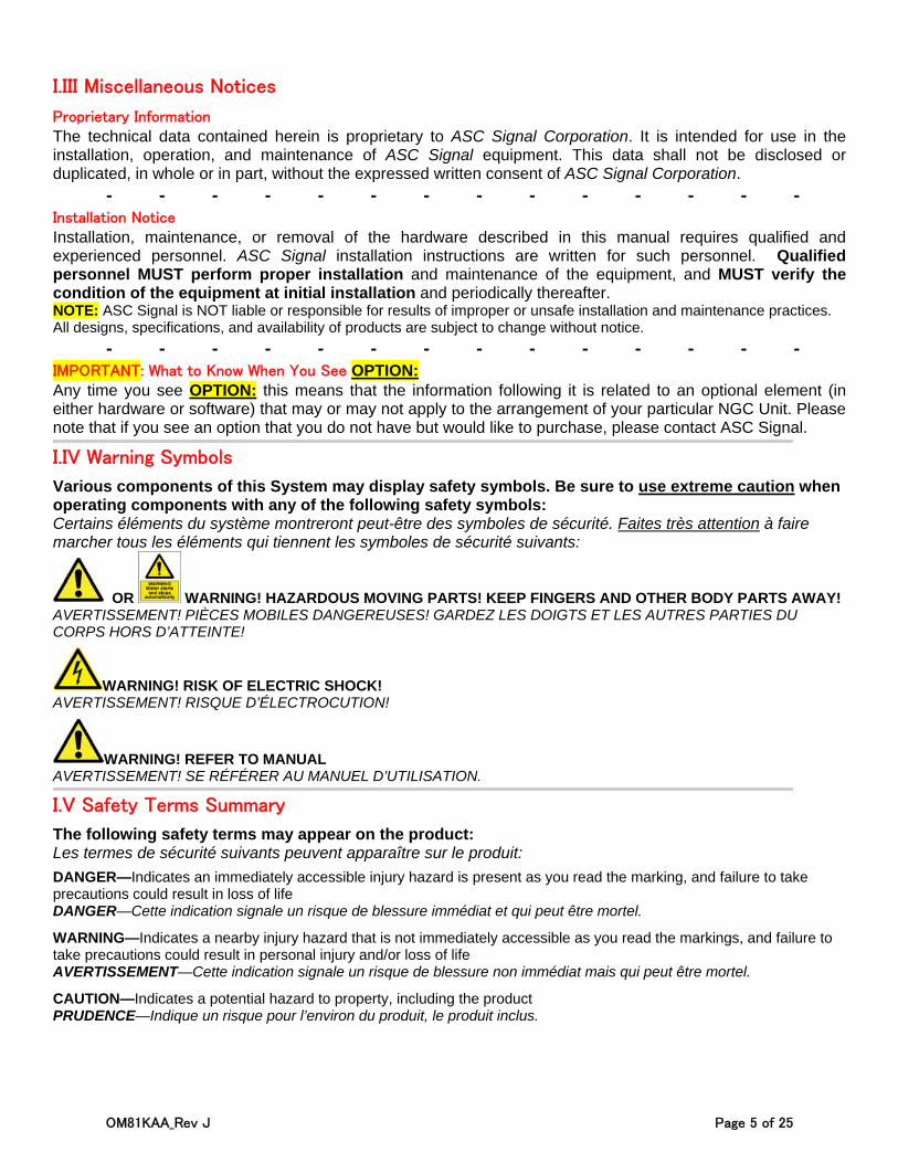
Various components of this System may display safety symbols. Be sure to use extreme caution when operating components with any of the following safety symbols: Certains éléments du système montreront peut-être des symboles de sécurité. Faites très attention à faire marcher tous les éléments qui tiennent les symboles de sécurité suivants:
OR WARNING! HAZARDOUS MOVING PARTS! KEEP FINGERS AND OTHER BODY PARTS AWAY! AVERTISSEMENT! PIÈCES MOBILES DANGEREUSES! GARDEZ LES DOIGTS ET LES AUTRES PARTIES DU CORPS HORS D’ATTEINTE!
WARNING! RISK OF ELECTRIC SHOCK! AVERTISSEMENT! RISQUE D’ÉLECTROCUTION!
WARNING! REFER TO MANUAL AVERTISSEMENT! SE RÉFÉRER AU MANUEL D’UTILISATION.
I.V Safety Terms Summary
The following safety terms may appear on the product: Les termes de sécurité suivants peuvent apparaître sur le produit:
DANGER—Indicates an immediately accessible injury hazard is present as you read the marking, and failure to take precautions could result in loss of life DANGER—Cette indication signale un risque de blessure immédiat et qui peut être mortel.
WARNING—Indicates a nearby injury hazard that is not immediately accessible as you read the markings, and failure to take precautions could result in personal injury and/or loss of life AVERTISSEMENT—Cette indication signale un risque de blessure non immédiat mais qui peut être mortel.
CAUTION—Indicates a potential hazard to property, including the product PRUDENCE—Indique un risque pour l’environ du produit, le produit inclus.

OM81KAA_Rev J Page 6 of 25
The following safety symbols and terms may be used in this manual: Les symbols et les termes suivants de sûreté peuvant être employés en ce manuel:
WARNING!/CAUTION! Statements identify conditions & practices that could result in injury or loss of life. AVERTISSEMENT! Les rapports d’avertissement identifient les conditions ou les pratiques qui pourraient avoir comme conséquence les dommages ou la perte de la vie.
RISK OF ELECTRIC SHOCK! RISQUE DE DÉCHARGE ÉLECTRIQUE!
I.VI Summary of Safety Precautions
The following safety precautions are not related to any specific procedure, and so will not appear elsewhere in this manual. Ensure all personnel understand & apply these precautions in all phases of installation, operation, & maintenance. Failure to do so may result in loss of life.
KEEP AWAY FROM LIVE CIRCUITS: Personnel must observe all applicable safety regulations at all times. Ensure power is disconnected or removed from the unit before replacing any components. Potential hazards may exist even though the power control switch is in OFF position. Capacitors retain electrical charges. Always remove power & use test equipment to confirm a circuit is at ground potential before touching it. Never reach into or enter an enclosure to service or adjust the equipment until the absence of power has been confirmed.
DO NOT SERVICE OR ADJUST ALONE: Under NO circumstances should ANY person reach into or enter the enclosure for the purpose of servicing or adjusting the equipment except in the presence of someone who is capable of rendering aid in case of an accident/emergency.
RESUSCITATION: Personnel working with or near high voltage should be familiar with resuscitation methods (CPR and/or AED). CPR info may be obtained from medical personnel. For AED (Automated External Defibrillator) information, contact supervisor or hosting administration for details on the availability and/or location of an AED unit at your worksite.
ELECTROSTATIC DISCHARGE PRECAUTION This equipment contains electrostatic discharge (ESD) sensitive devices. ESD sensitive equipment handling methods must be used to prevent equipment damage during handling and servicing.
ESSENTIAL HEALTH AND SAFETY REQUIREMENT Refer to document “P/N 240117—Essential Health and Safety Requirements”.
OM81KAA_Rev J Page 7 of 25
I.VII Things to Never Do
NEVER touch circuits or reach into an enclosure until the disconnection of power and absence of charge has been confirmed
NEVER service or adjust equipment alone. Electric shock can lead to cardiac arrest. Presence of immediate aid gives you a 90% chance of survival, but this drops by 10% with every passing minute. After 5 minutes resuscitation without permanent heart and/or brain damage is nearly impossible. Consider this: Without the immediate aid of CPR or an AED, what are the odds you will be found and successfully revived in less than 5 minutes?
NEVER ignore warning symbols or fail to read safety signs NEVER skip steps in a sequence, unless specifically instructed to do so by the manual, software, and/or
authorized ASC Signal Tech Support Personnel. Aside from risking harm to yourself, you risk doing permanent damage to the equipment
NEVER touch or stand near any potentially moving parts (even if they are not in motion at the time) when the unit is in operation or powered on, as they may move without warning
NEVER stand underneath any object while it is being lifted NEVER stand in front of, inside of, or near the antenna or feed while the antenna is in operation, as severe
eye damage and/or bodily injury may result from exposure to Radio Frequency (RF) radiation. NEVER begin any task without first donning the proper safety equipment for the situation (hardhats, gloves,
goggles, etc.) NEVER remove, disable, or exceed the unit’s safety, software, security, or movement limits, unless
specifically instructed to do so by the manual, software, and/or authorized ASC Tech Support Personnel. The careless disabling of such safeguards is one of the most common causes of serious equipment damage during installation and operation
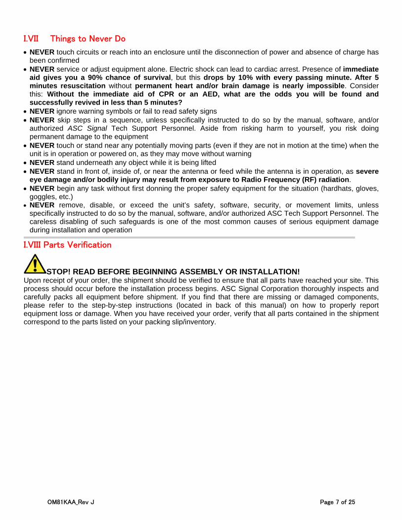
I.VIII Parts Verification
STOP! READ BEFORE BEGINNING ASSEMBLY OR INSTALLATION! Upon receipt of your order, the shipment should be verified to ensure that all parts have reached your site. This process should occur before the installation process begins. ASC Signal Corporation thoroughly inspects and carefully packs all equipment before shipment. If you find that there are missing or damaged components, please refer to the step-by-step instructions (located in back of this manual) on how to properly report equipment loss or damage. When you have received your order, verify that all parts contained in the shipment correspond to the parts listed on your packing slip/inventory.
OM81KAA_Rev J Page 8 of 25
1.0 Recommended Tools & Foundation Preparation
The following sections will offer you with information related to preparing to assemble and install the 8.1m ESA, such as recommended tools (Section 1.1) and foundation preparation (Section 1.3). The details of the A-325 tensioning procedure required for the tightening of all A-325 hardware will also be explained (Section 1.2).
1.1 Recommended Tools
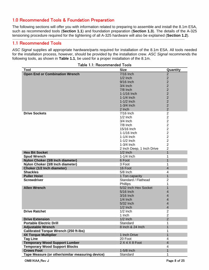
ASC Signal supplies all appropriate hardware/parts required for installation of the 8.1m ESA. All tools needed for the installation process, however, should be provided by the installation crew. ASC Signal recommends the following tools, as shown in Table 1.1, be used for a proper installation of the 8.1m.
Table 1.1: Recommended Tools Tool Size Quantity Open End or Combination Wrench 7/16 Inch
1/2 Inch 9/16 Inch 3/4 Inch 7/8 Inch 1-1/16 Inch 1-1/4 Inch 1-1/2 Inch 1-3/4 Inch 2 Inch
2 2 2 2 2 2 2 2 2 2
Drive Sockets 7/16 Inch 1/2 Inch 3/4 Inch 7/8 Inch 15/16 Inch 1-1/16 Inch 1-1/4 Inch 1-1/2 Inch 1-3/4 Inch 2 Inch Deep, 1 Inch Drive
2 2 2 2 2 2 2 2 2 2
Hex Bit Socket 1/2 Inch 1 Spud Wrench 1-1/4 Inch 1 Nylon Choker (3/8 Inch diameter) 6 Foot 1 Nylon Choker (3/8 Inch diameter) 3 Foot 1 Choker (1/2 Inch diameter) 16 Foot 4 Shackles 5/8 Inch 4 Puller Hoist 1 Ton capacity 1 Screwdriver Standard / Flathead
Phillips 2 1
Allen Wrench 5/32 Inch Hex Socket 5/16 Inch 3/16 Inch 1/4 Inch 5/32 Inch 1/2 Inch
1 4 4 4 4 4
Drive Ratchet 1/2 Inch 1 Inch
2 2
Drive Extension 1/2 Inch 2 Portable Electric Drill Standard 1 Adjustable Wrench 8 Inch & 24 Inch 1 Calibrated Torque Wrench (250 ft-lbs) 1 4X Torque Multiplier 1 Inch Drive 1 Tag Line 20 Foot 4 Temporary Wood Support Lumber 2 X 4 X 8 Foot 4 Temporary Wood Support Blocks 4 Crows Foot 1-5/8 Inch 1 Tape Measure (or other/similar measuring device) Standard 1
OM81KAA_Rev J Page 9 of 25
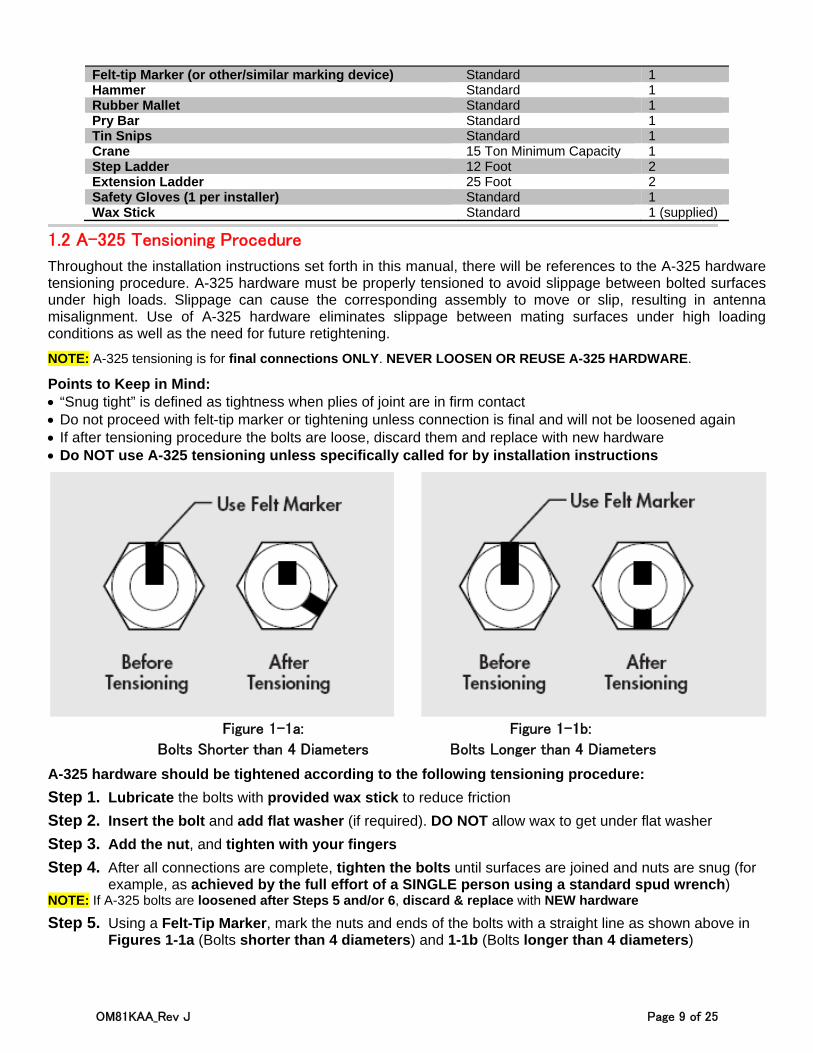
Felt-tip Marker (or other/similar marking device) Standard 1 Hammer Standard 1 Rubber Mallet Standard 1 Pry Bar Standard 1 Tin Snips Standard 1 Crane 15 Ton Minimum Capacity 1 Step Ladder 12 Foot 2 Extension Ladder 25 Foot 2 Safety Gloves (1 per installer) Standard 1 Wax Stick Standard 1 (supplied)
1.2 A-325 Tensioning Procedure
Throughout the installation instructions set forth in this manual, there will be references to the A-325 hardware tensioning procedure. A-325 hardware must be properly tensioned to avoid slippage between bolted surfaces under high loads. Slippage can cause the corresponding assembly to move or slip, resulting in antenna misalignment. Use of A-325 hardware eliminates slippage between mating surfaces under high loading conditions as well as the need for future retightening.
NOTE: A-325 tensioning is for final connections ONLY. NEVER LOOSEN OR REUSE A-325 HARDWARE.
Points to Keep in Mind: “Snug tight” is defined as tightness when plies of joint are in firm contact Do not proceed with felt-tip marker or tightening unless connection is final and will not be loosened again If after tensioning procedure the bolts are loose, discard them and replace with new hardware Do NOT use A-325 tensioning unless specifically called for by installation instructions
Figure 1-1a: Figure 1-1b:
Bolts Shorter than 4 Diameters Bolts Longer than 4 Diameters
A-325 hardware should be tightened according to the following tensioning procedure:
Step 1. Lubricate the bolts with provided wax stick to reduce friction
Step 2. Insert the bolt and add flat washer (if required). DO NOT allow wax to get under flat washer
Step 3. Add the nut, and tighten with your fingers
Step 4. After all connections are complete, tighten the bolts until surfaces are joined and nuts are snug (for example, as achieved by the full effort of a SINGLE person using a standard spud wrench)
NOTE: If A-325 bolts are loosened after Steps 5 and/or 6, discard & replace with NEW hardware
Step 5. Using a Felt-Tip Marker, mark the nuts and ends of the bolts with a straight line as shown above in Figures 1-1a (Bolts shorter than 4 diameters) and 1-1b (Bolts longer than 4 diameters)
OM81KAA_Rev J Page 10 of 25
Step 6. Tighten nuts even further, using an Extra-Long-Handled Wrench, until the nuts are:
Moved 1/3 TURN (120°) as shown in Figure 1-1a, shorter than 4 diameters (“After Tensioning”) Or 1/2 TURN (180°) as shown in Figure 1-1b, longer than 4 diameters (“After Tensioning”)
1.3 Foundation Preparation
Before beginning the installation process on the ground mount assembly, ensure that the foundation has been prepared. Foundation specifications are provided by ASC Signal and may be used as a reference by civil engineering personnel when preparing the foundation for local soil conditions. These specifications are available before the shipment arrives by contacting the Customer Service Center or your Account Manager.
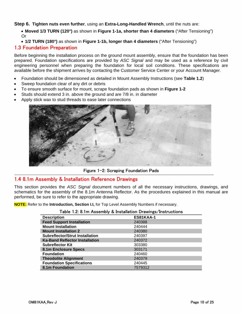
Foundation should be dimensioned as detailed in Mount Assembly Instructions (see Table 1.2) Sweep foundation clear of any dirt or debris To ensure smooth surface for mount, scrape foundation pads as shown in Figure 1-2 Studs should extend 3 in. above the ground and are 7/8 in. in diameter Apply stick wax to stud threads to ease later connections
Figure 1-2: Scraping Foundation Pads
1.4 8.1m Assembly & Installation Reference Drawings
This section provides the ASC Signal document numbers of all the necessary instructions, drawings, and schematics for the assembly of the 8.1m Antenna Reflector. As the procedures explained in this manual are performed, be sure to refer to the appropriate drawing.
NOTE: Refer to the Introduction, Section I.I, for Top Level Assembly Numbers if necessary.
Table 1.2: 8.1m Assembly & Installation Drawings/Instructions Description ES81KAA-1 Feed Support Installation 240388 Mount Installation 240444 Mount Installation 2 240380 Subreflector/Strut Installation 240397 Ka-Band Reflector Installation 240372 Subreflector Kit 303380 8.1m Enclosure Specs 303171 Foundation 240460 Theodolite Alignment 240379 Foundation Specifications 240445 8.1m Foundation 7579312
OM81KAA_Rev J Page 11 of 25
2.0 Mount & Antenna Assembly Procedures
These sections provide the basic sequence and tips for the assembly of various elements of the 8.1m ESA. Appropriate drawings and schematics references for assembly of the antenna are also provided, when applicable. Refer to the drawings, instructions, and schematics for the specific system being installed, per the information provided in Table 1.2.
2.1 Assembly Sequence & Helpful Tips
ASC Signal recommends following these helpful tips regarding the sequence of assembly: Always use the correct provided hardware and use the appropriate sequence for tightening/torque, as per
the instructions provided with the part or kit being assembled and/or installed (as listed in Table 1.2). As a rule, never fully tighten A-325 type hardware (see Section 1.2) unless instructed to do so by
instructions. Once tightened, A-325 cannot be loosened. If loosened, it must be replaced with new A-325 hardware.
The Mount should be assembled at ground level before beginning any hoisting with crane. The Reflector & Back Structure should be assembled at ground level before beginning any hoisting with
crane. Theodolite Alignment should be performed at ground level before beginning any hoisting with crane. During assembly of the Azimuth Jackscrew, ensure that the Azimuth Jackscrew assembly is in the fully
retracted position. During Panning Frame assembly, insert bolts from the inside of the Panning Frame. During hoisting (with crane) of the Motor/Jack Assembly, do NOT attach any ropes to the Small Motor. Always attach hoisting ropes in such a way that moving parts will not drop/rotate when lifted. Realignment of the Panning Frame/Pivot Assembly may be necessary to ensure proper alignment of the
Azimuth Jackscrew pin. Make snug the Panning Frame/Pivot Assembly hardware and fully extend the Azimuth Jackscrew so that binding does not occur along the full range of the Azimuth Pivot.
The following steps represent the recommended (but not required) basic sequence of assembly for this antenna: NOTE: More steps may be required, in addition to those listed below, depending on the antenna type and/or the presence of particular options. Refer to Table 1.2 to locate document numbers for the system being installed. Such documents will be provided in the shipment of each part, kit, and/or option.
1. Mount Assembly: Refer to instructions per Table 1.2
2. Reflector & Back Structure Assembly: Refer to instructions per Table 1.2
3. Feed Support Installation: Refer to instructions per Table 1.2
4. Theodolite & Alignment: Refer to instructions per Table 1.2
5. Feed Rotation Drive Installation: Refer to instructions per Table 1.2
6. Subreflector Assembly & Installation: Refer to instructions Table 1.2
OM81KAA_Rev J Page 12 of 25
2.2 General Subreflector Alignment Guidelines
The primary goal of Subreflector alignment is for the Subreflector to be properly centered and for the height to be adjusted to the correct focal length for the antenna.
Keep the following guidelines in mind during Subreflector alignment: A tape measure is generally used in order to center the Subreflector Measure from a repeatable location, running the tape measure from the 4 locations where the strut ends
meet the main reflector to the inside edge of the Subreflector For centering measurements, a zero delta between all is ideal Focal length is measured from the antenna vertex to the edge of the Subreflector at the three Adjustment
Rod locations on the Subreflector Target focal length distance is determined by antenna type Normally, the process of centering the Subreflector then the Subreflector height is repeated until both
centering and height are “nuts on” precise
OM81KAA_Rev J Page 13 of 25
3.0 Operation
After completing the assembly of the antenna, the 8.1m ESA is ready to become operational. To operate the 8.1m ESA, it is necessary to direct it to the desired satellite and adjust both Elevation and Azimuth angles appropriately. These procedures provide details on how to correctly position the antenna on a desired satellite. NOTE: If intending to use an ASC Signal NGC Indoor Unit (NGC-IDU) or NGC Outdoor Unit (NGC-ODU) in order to control antenna, it is best to refer to the appropriate manuals of the NGC Documentation Package received with that unit.
3.1 Acquiring Satellites
There are a number of possible procedures for acquiring a satellite. ASC Signal recommends that a Spectrum Analyzer of some type be used, regardless of your chosen procedure.
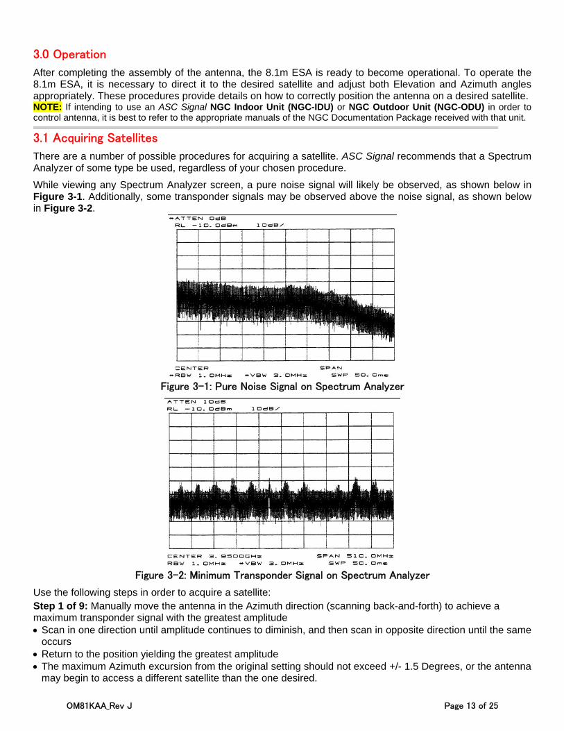
While viewing any Spectrum Analyzer screen, a pure noise signal will likely be observed, as shown below in Figure 3-1. Additionally, some transponder signals may be observed above the noise signal, as shown below in Figure 3-2.
Figure 3-1: Pure Noise Signal on Spectrum Analyzer
Figure 3-2: Minimum Transponder Signal on Spectrum Analyzer
Use the following steps in order to acquire a satellite: Step 1 of 9: Manually move the antenna in the Azimuth direction (scanning back-and-forth) to achieve a maximum transponder signal with the greatest amplitude Scan in one direction until amplitude continues to diminish, and then scan in opposite direction until the same
occurs Return to the position yielding the greatest amplitude The maximum Azimuth excursion from the original setting should not exceed +/- 1.5 Degrees, or the antenna
may begin to access a different satellite than the one desired.
OM81KAA_Rev J Page 14 of 25
Step 2 of 9: With the antenna positioned in Azimuth, with the transponder signal maximized, follow the same procedure as in Step 1, only this time using the Elevation direction (scanning up-and-down). Once again, do this until the transponder signal has been maximized.
Step 3 of 9: Repeat this procedure, alternating between the Azimuth and Elevation excursions of the antenna, until you have peaked the antenna transponder amplitude. Transponder signal amplitude of 30 dB or greater from peak to average noise signal indicates that the
antenna is receiving the signal on the main beam. Transponder signal amplitude of less than 30 dB indicates the antenna is peaking on a side lobe of the main
beam.
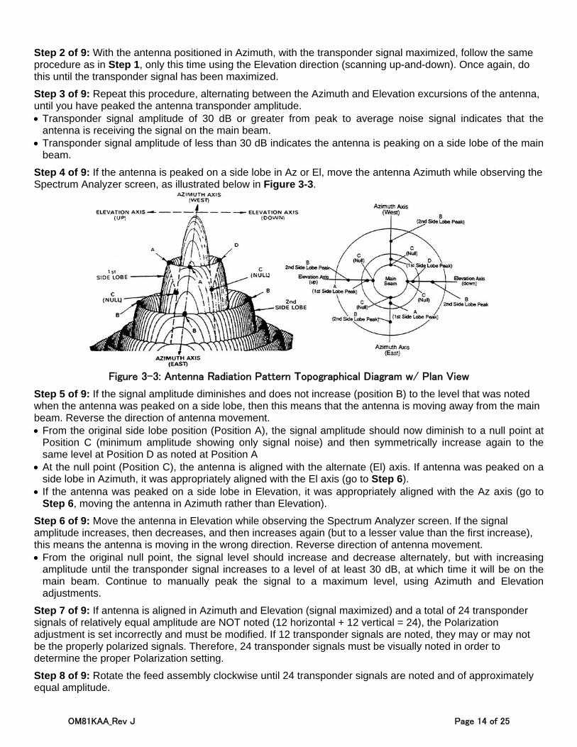
Step 4 of 9: If the antenna is peaked on a side lobe in Az or El, move the antenna Azimuth while observing the Spectrum Analyzer screen, as illustrated below in Figure 3-3.
Figure 3-3: Antenna Radiation Pattern Topographical Diagram w/ Plan View
Step 5 of 9: If the signal amplitude diminishes and does not increase (position B) to the level that was noted when the antenna was peaked on a side lobe, then this means that the antenna is moving away from the main beam. Reverse the direction of antenna movement. From the original side lobe position (Position A), the signal amplitude should now diminish to a null point at
Position C (minimum amplitude showing only signal noise) and then symmetrically increase again to the same level at Position D as noted at Position A
At the null point (Position C), the antenna is aligned with the alternate (El) axis. If antenna was peaked on a side lobe in Azimuth, it was appropriately aligned with the El axis (go to Step 6).
If the antenna was peaked on a side lobe in Elevation, it was appropriately aligned with the Az axis (go to Step 6, moving the antenna in Azimuth rather than Elevation).
Step 6 of 9: Move the antenna in Elevation while observing the Spectrum Analyzer screen. If the signal amplitude increases, then decreases, and then increases again (but to a lesser value than the first increase), this means the antenna is moving in the wrong direction. Reverse direction of antenna movement. From the original null point, the signal level should increase and decrease alternately, but with increasing
amplitude until the transponder signal increases to a level of at least 30 dB, at which time it will be on the main beam. Continue to manually peak the signal to a maximum level, using Azimuth and Elevation adjustments.
Step 7 of 9: If antenna is aligned in Azimuth and Elevation (signal maximized) and a total of 24 transponder signals of relatively equal amplitude are NOT noted (12 horizontal + 12 vertical = 24), the Polarization adjustment is set incorrectly and must be modified. If 12 transponder signals are noted, they may or may not be the properly polarized signals. Therefore, 24 transponder signals must be visually noted in order to determine the proper Polarization setting.
Step 8 of 9: Rotate the feed assembly clockwise until 24 transponder signals are noted and of approximately equal amplitude.
OM81KAA_Rev J Page 15 of 25
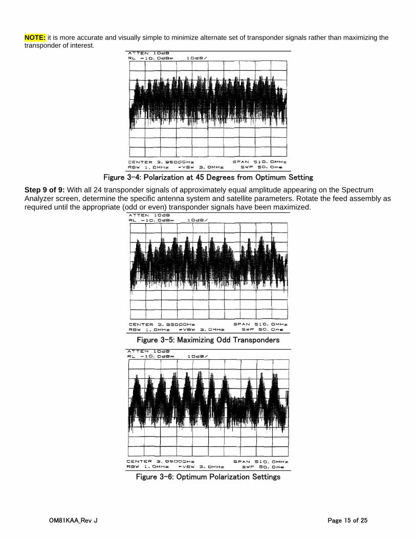
NOTE: it is more accurate and visually simple to minimize alternate set of transponder signals rather than maximizing the transponder of interest.
Figure 3-4: Polarization at 45 Degrees from Optimum Setting
Step 9 of 9: With all 24 transponder signals of approximately equal amplitude appearing on the Spectrum Analyzer screen, determine the specific antenna system and satellite parameters. Rotate the feed assembly as required until the appropriate (odd or even) transponder signals have been maximized.
Figure 3-5: Maximizing Odd Transponders
Figure 3-6: Optimum Polarization Settings

OM81KAA_Rev J Page 16 of 25
3.2 Subreflector Adjustment
After the satellite has been acquired and testing has taken place with the Spectrum Analyzer, the subreflector may need to be adjusted to maximize optimum performance of your antenna. The following procedures should be followed if a subreflector adjustment is required to maximize optimum performance. NOTE: All INTELSAT Type Approved antennas do not require subreflector adjustment.
Before proceeding, the Azimuth and Elevation patterns should be conducted to determine any adjustments that need to be made. The goal is to achieve a high peak on the main lobe and even distances between the main lobe and sidelobes as shown in Figure 3-6. NOTE: No adjustments should be made in the receive band.
If your pattern dictates a need to adjust the Azimuth angle (the left side lobe requires adjustment), the west side of the subreflector should be adjusted outward by loosening the screws on the subreflector and adjusting the left side outward. An easy way to remember this adjustment feature is through the acronym WOLD (West Out, Left Down).
If your pattern dictates a need to adjust the elevation angle (the right sidelobe requires adjustment), the bottom side of the subreflector should be adjusted downward by loosening the screws between the subreflector and the struts and adjusting the bottom side of the subreflector downward. An easy way to remember this adjustment is through the acronym BOLD (Bold Out, Left Down).
Each of these adjustments should be repeated until each sidelobe is of equal distance from the peak of the main lobe.
After the BOLD and WOLD adjustments have been made, it may be necessary to adjust the main lobe. The goal is to achieve a high null depth (distance between lower intersection of side lobes and top of main lobe) as shown in Figure 3-6.
In order to adjust the main lobe pattern characteristics ALL subreflector adjustment screws should be adjusted at the same degree (Note: Because the azimuth and elevation adjustments have been set, it is very important that the null depth adjustment be carefully conducted. Be careful not to alter any previous adjustments that have been made to the subreflector. Follow the procedure listed below when adjusting the null depth of the main lobe.
C-Band feeds – Adjustment screws are 3/4 X 10. Move 1 turn per 1dB of imbalance.
Ku-Band feeds – Adjustment screws are 1/4 X 20. Move 1 turn per 1 dB of imbalance.
All adjustments should be continued until the desired pattern is achieved. Upon completion, the antenna should be properly aligned with the satellite for maximum performance.
OM81KAA_Rev J Page 17 of 25
4.0 Preventive Maintenance
These sections contain periodic preventative maintenance instructions for the 8.1m Earth Station Antenna. Included are instructions for performing inspections, preventative maintenance procedures, and cleaning. NOTE: Refer to applicable vendor manuals for any repair procedures that are not included in this manual.
These sections describe cleaning, inspections, and preventative maintenance procedures. Regularly replacing normally functioning assemblies or components as a preventative measure is not required. Malfunctions of this ESA can normally be traced to components and/or parts through the use of troubleshooting procedures.
4.1 General Cleaning
To prevent excessive accumulation of dust and dirt, as well as to ensure the removal of various contaminants, the equipment needs to be thoroughly cleaned. It is recommended that you clean the antenna every time you conduct a visual inspection of the components. No special cleaning procedures are required. However, to ensure trouble-free operation you will need to clean in accordance with procedures in Sections 4.1.1 & 4.1.2.
‐ ‐ ‐ ‐ ‐ ‐ ‐ ‐ ‐ ‐ ‐ ‐ ‐ ‐ 4.1.1 Electrical Parts
CAUTION: Confirm ALL ELECTRICAL POWER IS REMOVED BEFORE proceeding. Minor cleaning, such as the removal of dust and loose foreign particles, can be accomplished by one or all of the following methods: Vacuuming Using a soft-bristle brush or lint-free cloth Using an air compressor, with dry air at a LOW PRESSURE (between 5 and 25 psi), to blow out dust
and dirt NOTE: When using air to clear contaminants, take extreme care when blowing air stream on or near ANY delicate parts.
To remove imbedded dirt, grease, and/or oil from electrical parts: Use a 50% solution of Isopropyl “rubbing” alcohol Apply to surface with a soft-bristle brush
NOTE: At times, it may be necessary to brush some parts vigorously with a stiff bristle brush in order to remove imbedded or hardened dirt particles. NOTE: After cleaning, ALLOW CLEANED PARTS TO DRY FOR 10-15 MINUTES before restoring power and/or returning equipment to operation.
‐ ‐ ‐ ‐ ‐ ‐ ‐ ‐ ‐ ‐ ‐ ‐ ‐ ‐ 4.1.2 Mechanical parts Cleaning of mechanical parts begins by removing dust, dirt, and other loose contaminants with a scraper, stiff-bristle brush (or wire brush in cases of rust or corrosion removal), lint-free cloth, or compressed air (pressure between 25 and 40 psi). Any accumulation of imbedded dirt, corrosion, grease, or oil deposits which require more cleaning may be removed with a stiff-bristle or wire brush, along with a cleaning solvent such as acetone (or equivalent).
NOTE: After cleaning, ALLOW CLEANED PARTS TO DRY FOR 10-15 MINUTES before restoring power and/or returning equipment to operation.
4.2 Inspections
The frequency of inspection is contingent upon the user’s individual standards and the operational environment in which the earth station antenna is located. However, a visual inspection of the components should be performed at least semi-annually. Where there are no established wear limits, perform a visual inspection to locate worn or damaged parts that could result in a malfunction of the earth station antenna. It is recommended that the mechanical and electrical inspections be performed on the assembled or partially disassembled equipment to determine the extent of disassembly required prior to completely disassembling a component or module that is suspected of malfunctioning.
OM81KAA_Rev J Page 18 of 25
In the absence of any special inspection requirements, operational tests are the most effective means in isolating parts and assemblies requiring further inspection. During inspection, any noted damage and/or problematic condition which could preclude the continuation of proper operation (prior to the next scheduled inspection) should be recorded. These discrepancies should be immediately corrected (either by repair or replacement, as required), or dealt with immediately after the inspection procedure has been completed.
CAUTION: Allowing the antenna to continue to operate after damage or discrepancies have been noted during inspection may result in property damage (especially to your earth station antenna), as well as increase the risk of creating dangerous situations for personnel, causing personal injury and/or loss of life.
‐ ‐ ‐ ‐ ‐ ‐ ‐ ‐ ‐ ‐ ‐ ‐ ‐ ‐ 4.2.1 Local Control/Motor Drive Controller Inspection For details on inspections for the Local Control/Motor Drive Controller, refer to the appropriate antenna control documentation.
‐ ‐ ‐ ‐ ‐ ‐ ‐ ‐ ‐ ‐ ‐ ‐ ‐ ‐ 4.2.2 Antenna Inspection Inspection of the antenna generally conforms to standard visual inspection procedures performed on electromechanical equipment. In addition to these procedures, perform the following checks and visual inspections for the specific conditions as noted:
Inspect all wiring and cables, particularly the network-to-enclosure and enclosure-to-mount interfaces, for discolored and/or burned insulation, entry of water/moisture, corrosion, dirt, breaks, secure connections, and any other signs of damage or deterioration. Examine connections for dirt, corrosion, and mechanical defects. Check for loose or broken lacing, as well as cuts, braiding, dry rot, or cracks in insulation
Inspect all connectors for corrosion, broken inserts, and stripped threads. Inspect connector shells, checking for distortion and dents. Inspect contact pins for bends, misalignment, and/or other deformities. Check connector inserts for carbon tracking, burns, or charring, indicating arc-over
Check all electrical components for dirt, cracks, chips, breaks, discoloration, and any other signs of damage or deterioration. Discoloration, blistering, or burns are evidence of overload(s). Measure the actual value(s) of any suspect electrical components (as with a digital multimeter) and compare against value(s) in the product’s specifications
Operate the Azimuth and Elevation drives, as well as the feed rotation (if applicable) in both the plus and minus direction from the local control/motor drive controller at least once every three (3) months during antenna down time. Check to make sure the mechanical Hard Limit switches stop the antenna and feed movement, and limit travel to prevent structural interference and damage. Check the mechanical Hard Limit switches for corrosion and water entry. Check the arm on the feed limit switch for free movement, with no binding or interference. Be certain both of the feed rotation limit switch arms are not distorted and ride centrally on the actuating cam to open their corresponding Hard Limit switch
Inspect the Azimuth and Elevation Jackscrew boots for security of attachment at both ends, checking for abrasions, tears, cuts, dry rot, and other damage that might expose the jackscrew to environmental conditions (rain/water/ice, dust, etc.). Minor repairs can be made by resealing compromised areas with RTV-108 silicone rubber sealant
Visually inspect the feed window for dirt. Check the feed, feed supports, feed window, and reflector for distortion, foreign object damage, and environmental deterioration (due to snow/ice, rain, hail, high winds, etc.). Environmental deterioration can result in damage and/or deformation of both the electrical components and the structure
Check the cable attachment to the resolvers, to the LNA/LNB, and the enclosure-to-mount interface for security. Check the cable routing for secure hanger attachment. Check cable insulation for cuts, cracks, abrasions, and other signs of damage or deterioration. Check LNA/LNB and resolvers for secure mechanical attachments. Ensure there is proper torque in setscrews of Polarization drive gear box, and proper tensioning of corresponding drive chain assembly (if applicable)
OM81KAA_Rev J Page 19 of 25
IF APPLICABLE, check that drain holes in bottom of the enclosure and pedestal are not obstructed, and there is no evidence of water accumulation. Check enclosure doors for proper closure. Verify door seals are intact and free of tears, abrasions, and/or other damage. Check that all other seals are intact, and repair with coating of RTV-108 silicone rubber sealant as needed to seal exposed electrical fittings, bolt holes, and/or any other points of possible water entry to electrical components to maintain a waterproof condition. If enclosure has a vent fan, inspect fan blade for freedom of operation. Fan bearings are permanently lubricated. However, any binding, abnormal noises, and/or vibration means replacement of the fan assembly is needed. Check fan filter element and, dirty or obstructed with dust, replace it.
Visually inspect all mechanical parts for freedom of operation with no misalignment, binding, or interference. Check all cabling for sufficient slack in order to prevent cable strain while still providing enough restraint to adequately prevent abrasions and/or chaffing during antenna and feed movement
Check antenna mounting and interconnecting assembly hardware for security. Verify that all electrical grounding connections (including cross-axis grounding straps) are intact and secure, free of corrosion or breaks. Use a wire brush to thoroughly clean any noticeably corroded portions of grounding cables, the un-plated portion of universal terminals, and corresponding mounting surfaces. ANY LOOSE A-325 HARDWARE MUST BE REPLACED RATHER THAN TIGHTENED. A-325 hardware distorts at initial installation and, once loosened, will not maintain the required high strength friction connection. All other (not A-325) assembly and installation hardware should be tightened to its original torqued condition. When installing new structural hardware, do not use a wrench with a lever arm longer than two (2) feet
Examine all painted aluminum or galvanized surfaces for chips, cracks, or deep gouges, and touch-up spots as needed
‐ ‐ ‐ ‐ ‐ ‐ ‐ ‐ ‐ ‐ ‐ ‐ ‐ ‐ 4.2.3 Drive System Voltage & Current Checks For details on Drive System Voltage and Current Checks, refer to the appropriate antenna control documentation.
4.3 Preservation & Lubrication of Component Parts ‐ ‐ ‐ ‐ ‐ ‐ ‐ ‐ ‐ ‐ ‐ ‐ ‐ ‐ 4.3.1 Preservation of Aluminum Parts Remove all loose paint and corrosion by scraping, wire brushing, or using steel wool. If using steel wool near the feed window, make sure that none remains on the feed horn window. Edges of existing paint can be blended with the metal surface using fine grit sandpaper. Wipe the surface to be painted with a soft rag dampened with a small amount of acetone or equal. Be certain to remove all loose paint, corrosion, imbedded dirt, grease, and oil deposits or the paint will not adhere to the surface. Acetone will dissolve paint if applied heavily and rubbed vigorously. The reflector may be washed with plain water if necessary. Do not use bleach, soap solutions, or kerosene as it is difficult to remove the residue. Allow the cleaned surface to dry thoroughly before priming.
Prime the cleaned surface by applying zinc chromate primer. The primer can be applied with a brush, roller, or pressurized spray. If necessary, thin the primer with acetone to the proper consistency. Feather the primer onto the adjacent painted surfaces. Allow primer to thoroughly dry before applying the finish paint coat.
Paint all RF surfaces, such as the inside of the main reflector and subreflector with highly-reflective white paint. This type of paint disperses light rays, reducing the focusing effect of the sun’s radiation, thereby reducing heat build-up caused by the focused sunrays on the feed system. Rear surfaces of the reflector and subreflector may be painted with flat-white enamel paint. The paint can be applied with a brush, roller, or pressurized spray. If necessary, thin the paint with the appropriate thinner to the proper consistency. Thoroughly paint over the primed surfaces and blend with the existing painted surface.
‐ ‐ ‐ ‐ ‐ ‐ ‐ ‐ ‐ ‐ ‐ ‐ ‐ ‐
OM81KAA_Rev J Page 20 of 25
4.3.2 Preservation of Galvanized Surfaces Remove all loose paint and corrosion by scraping, wire brushing, or using steel wool. Edges of existing paint can be blended with the metal surface using fine grit sandpaper. Wipe the surface to be painted with a soft rag dampened with a small amount of acetone, or equal. Be certain to remove all loose paint, corrosion, imbedded dirt, grease, and oil deposits or the paint will not adhere to the surface. Acetone will dissolve paint if applied heavily and rubbed vigorously. Do not use bleach, soap solutions, or kerosene as it is difficult to remove the residue. Allow the clean surface to dry thoroughly before painting.
Paint the cleaned surface with a zinc-rich paint. The paint can be applied with a brush, roller, or pressurized spray. If necessary, thin the paint with the appropriate thinner to the proper consistency. Thoroughly paint over the cleaned surface and blend with the existing painted surface.
‐ ‐ ‐ ‐ ‐ ‐ ‐ ‐ ‐ ‐ ‐ ‐ ‐ ‐4.3.3 Lubrication For long life and trouble-free operation be certain not to extend the lubrication schedule beyond the frequency recommended in the Lubrication Chart. The frequency should be shortened if the antenna is subjected to an adverse environment (e.g., high temperature, extended periods of rainfall, high humidity, dust storms, etc). Any component or part should immediately be lubricated if during inspection or operation, rough, jarring, or intermittent motion is noted, or if squeaky or other unusual noises are heard. Lubrication is required on all metal-to-metal rolling or sliding parts. Us the lubricants recommended. Do not over lubricate. Over lubrication can often be as damaging as under lubrication. Prior to the application of lubricant to any parts, use a clean cloth and/or bristle brush and remove any old lubricant to prevent an excessive build-up. Be certain to remove any protective caps and clean each lubricated fitting prior to injecting fresh grease. The Elevation and Azimuth Jackscrew Assemblies are equipped with a grease fitting and corresponding pipe plug on opposite sides of the jack housing. Remove the appropriate pipe plug and fill with grease until lubricant seeps from the pipe plug opening. Replace and securely tighten pipe plug.
The following is a list of the lubricant characteristics:
Mobil Temp SHC100: A non-soap hydrocarbon fluid type grease. Operating temperature range is -65 degrees to 350+ degrees Fahrenheit (-64 degrees to 177+ degrees Celsius).
Moly Grease: grease lubricant containing molybdenum disulfide. Operating temperature range is -85 degrees to 300+ degrees Fahrenheit (-29 degrees to 149+ degrees Celsius).
‐ ‐ ‐ ‐ ‐ ‐ ‐ ‐ ‐ ‐ ‐ ‐ ‐ ‐ 4.3.4 Lubrication of Jackscrews/Motors Periodically inspect lifting screws on jackscrew ballscrew assemblies to ensure adequate lubrication. Loosen Jackscrew ballscrew boot clamps to expose the lifting screw assembly. Fully extend jackscrew assembly being careful not to exceed preset mechanical limits. Brush thin coating of SHC100 grease on exposed lifting screw. Replace boot and attach corresponding boot clamps. If lifting screw is rusty, remove existing lubricant with solvent and wire brush rusted area. Rinse with solvent and apply fresh grease.
Periodically inspect and remove dust or dirt deposits from the motor housings to avoid hindering the heat exchange with the ambient air. Slight dirt accumulation on the air vent screw through splash oil cannot be avoided; however, keep vent screw clean to ensure proper pressure compensation.
‐ ‐ ‐ ‐ ‐ ‐ ‐ ‐ ‐ ‐ ‐ ‐ ‐ ‐ 4.3.5 Lubrication of Gear Motor/Housing Fill Drain Requirements Lube point 1 as shown in the Lubrication Chart (Table 5.1), require removal of the indicated drain plugs and, by using a measuring cup, to collect and measure the amount of SHC100 oil that drains out. The specified amount of oil must be added to the gear motor/housing (after the drain plug has been reinstalled), using a supplied funnel to pour new oil into the fill/vent plug opening. The addition of oil requires the use of an appropriate filling utensil. Use of a modified level stick will NOT correctly gauge the appropriate amount of oil that is present in the gear housings.
OM81KAA_Rev J Page 21 of 25
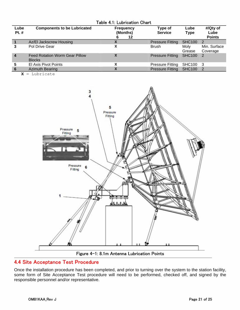
Table 4.1: Lubrication Chart Lube Pt. #
Components to be Lubricated Frequency (Months) 6 12
Type of Service
Lube Type
#/Qty of Lube
Points 1 Az/El Jackscrew Housing X Pressure Fitting SHC100 2 3 Pol Drive Gear X Brush Moly
Grease Min. Surface Coverage
4 Feed Rotation Worm Gear Pillow Blocks
X Pressure Fitting SHC100 2
5 El Axis Pivot Points X Pressure Fitting SHC100 3 6 Azimuth Bearing X Pressure Fitting SHC100 2
X = Lubricate
Figure 4-1: 8.1m Antenna Lubrication Points
4.4 Site Acceptance Test Procedure
Once the installation procedure has been completed, and prior to turning over the system to the station facility, some form of Site Acceptance Test procedure will need to be performed, checked off, and signed by the responsible personnel and/or representative.
OM81KAA_Rev J Page 22 of 25
5.0 Corrective Maintenance & Troubleshooting
The following sections will offer information, instructions, and guidelines regarding issues of corrective maintenance such as painting, backlash adjustment, and maintenance kits.
5.1 Top 5 ESA Maintenance & Troubleshooting FAQ
1. What should be done about chips, cracks, scratches, etc., in the paint of the reflector and/or other ESA surfaces? Priming and/or painting certain surfaces of the ESA is permitted and advisable under specific conditions such as gouges, scratches, etc. in the surface of the reflector paint (refer to Section 5.2 for detailed instructions).
2. How can I remove Backlash? Backlash is removed by performing anti-backlash Jack Adjustment (for detailed instructions, see Section 5.3)
3. Are there any particular kits available for purposes of maintenance? A number of maintenance kits are available for this particular antenna. A list of these kits may be found in Table 5.1 (refer to Section 5.4).
4. Are there any particular precautions that can be taken to avoid damaging the feed window? All ASC Signal ESA feed windows are rated at .5 psi. This means placing any pressure on the feed window of more than .5 psi is likely to cause permanent damage to feed window, which will require replacement.
5. What is the proper stow procedure for the 8.1m antenna? In order to move the antenna to stow position, point the antenna to an Elevation angle of 35° (± 3°). The Azimuth jackscrew should be placed in the center of its travel. In preparation for extreme winds, such as the approach of a hurricane, antenna should be moved to this position. Stow positioning must be performed before wind speeds reach 45mph.
5.2 Corrective Painting Instructions
The following sections offer detailed instructions for corrective painting of particular surfaces on the Earth Station Antenna. Please keep in mind that only qualified personnel should be allowed to perform these procedures. Also, be certain to read all of the following sections thoroughly BEFORE proceeding.
‐ ‐ ‐ ‐ ‐ ‐ ‐ ‐ ‐ ‐ ‐ ‐ ‐ ‐ 5.2.1 Preparatory Cleaning of Aluminum Surfaces Remove all loose paint and/or rust from the surface to be painted using a scraper, wire brush, or steel wool. If steel wool is used, take care to ensure that none of it is left on the reflector or feed horn window after cleaning (steel wool tends to leave behind particles). Wipe the surface to be painted with acetone using a soft rag. However, keep in mind that the acetone will also dissolve the surrounding paint if used too heavily and/or rubbed too hard. Paint edges can be blended to the metal using very fine grit sandpaper. If necessary, the surface of the reflector may be washed clean using plain water.
IMPORTANT NOTE: Do NOT use bleach, soap, cleaning solutions, or kerosene, as these substances leave behind residue that is difficult to remove.
‐ ‐ ‐ ‐ ‐ ‐ ‐ ‐ ‐ ‐ ‐ ‐ ‐ ‐ 5.2.2 Priming Cleaned Aluminum Surfaces Apply a thin coat (approximately .5 to 1 mil) of primer and feather paint it onto the adjacent painted areas.
Allow the primer to dry thoroughly (4-5 hours, depending on environmental conditions) before applying a finish coat of primer.
Allow the finish coat of primer to dry thoroughly (8-12 hours) before proceeding.
‐ ‐ ‐ ‐ ‐ ‐ ‐ ‐ ‐ ‐ ‐ ‐ ‐ ‐
OM81KAA_Rev J Page 23 of 25
5.2.3 Painting Primed Aluminum Surfaces For antenna surfaces, such as the front or back of the main reflector or subreflector, high-reflectivity white paint should be used. This type of paint disperses light rays. The paint may be applied to the prepared area using a brush, roller, or sprayer. If a sprayer is used, be sure to first thin the paint to a proper consistency with paint thinner (10-15% thinner).
Thoroughly cover all previously primed areas with paint and blend the paint with any preexisting painted surfaces.
‐ ‐ ‐ ‐ ‐ ‐ ‐ ‐ ‐ ‐ ‐ ‐ ‐ ‐5.2.4 Prepping & Painting Galvanized Surfaces Remove all loose paint or rust using a scraper, wire brush, or sanding.
Wipe clean the surface to be painted with a soft cloth rag and acetone.
Allow the acetone to dry thoroughly before applying the finish coat of primer.
Apply a zinc-rich paint as the final finish, thoroughly covering any previously primed surfaces.
‐ ‐ ‐ ‐ ‐ ‐ ‐ ‐ ‐ ‐ ‐ ‐ ‐ ‐ 5.2.5 Priming & Painting Cleaned Jack Surfaces Be sure to read ALL of the following instructions/guidelines BEFORE proceeding:
Surface Preparation – Use acetone and a soft cloth rag to remove all grease from the surface to be coated.
Mixing – Use a power mixer to bring the paint to a uniform consistency before using.
Thinning – In the case of Jack Surfaces, thinning the paint is not normally required for most brush, roller, or sprayer applications.
Using a Brush or Roller – Using a foam brush, apply paint to surface with full, single strokes. Avoid any re-brushing. Using a medium nap roller apply paint to surface in long, single rolls. Avoid rerolling. The recommended dry film thickness per coat is 2 mils (50 micron).
Allow Each Coat to Dry Thoroughly – Use the below chart (Table 5.1) to determine drying times. These times are based on a 2 mil (50 micron) dry film thickness. Conditions such as higher film thickness, insufficient ventilation, and/or cooler temperatures will likely require cure times to be extended. Allow the primer to dry thoroughly before applying the topcoat. Application of the topcoat should be done based on the above instructions.
Table 5.1: Cure Times Temperature Touch Handle Topcoat 75° F (24° C) 4 hours (Primer) 12 hours 8 hours 75° F (24° C) 5 Hours (Topcoat) 24 hours
5.3 Removing Backlash via Jack Adjustment
The backlash removal feature is a factory setting and does not normally require any additional adjustment. However, as time and extended use can lead to the development of wear, it may eventually become necessary to perform a Jac/Jack Anti-Backlash Adjustment in order to reduce/remove backlash.
Use the following procedure for Jac/Jack Anti-Backlash Adjustment:
1. Loosen the Locknut (item b in Figure 5-1).
2. Loosen the Setscrews (item c in Figure 5-1).
3. In order to reduce backlash, rotate the Adjusting Cap (item a in Figure 5-1) in a clockwise direction until able to feel resistance.
NOTE: Do NOT over-tighten the Adjusting Cap.
4. Using a felt-tip marker (or equivalent), place a reference mark between the thread on the Adjusting Cap and the Housing.
OM81KAA_Rev J Page 24 of 25
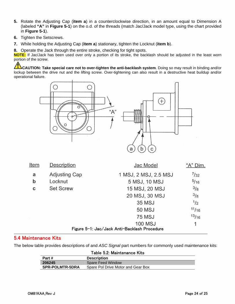
5. Rotate the Adjusting Cap (item a) in a counterclockwise direction, in an amount equal to Dimension A (labeled “A” in Figure 5-1) on the o.d. of the threads (match Jac/Jack model type, using the chart provided in Figure 5-1).
6. Tighten the Setscrews.
7. While holding the Adjusting Cap (item a) stationary, tighten the Locknut (item b).
8. Operate the Jack through the entire stroke, checking for tight spots. NOTE: If Jac/Jack has been used over only a portion of its stroke, the backlash should be adjusted in the least worn portion of the screw.
CAUTION: Take special care not to over-tighten the anti-backlash system. Doing so may result in binding and/or lockup between the drive nut and the lifting screw. Over-tightening can also result in a destructive heat buildup and/or operational failure.
Figure 5-1: Jac/Jack Anti-Backlash Procedure
5.4 Maintenance Kits
The below table provides descriptions of and ASC Signal part numbers for commonly used maintenance kits:
Table 5.2: Maintenance Kits Part # Description 206245 Spare Feed Window SPR-POLMTR-5DRA Spare Pol Drive Motor and Gear Box
OM81KAA_Rev J Page 25 of 25
APPENDIX: Equipment Issues & Technical Support
REPORTING EQUIPMENT LOSS OR DAMAGE If you find equipment was damaged during the shipping process, file a claim with the carrier. Follow the “Reporting Visible Loss or Damage” or “Reporting Concealed Damage” procedures to file a claim with a carrier.
REPORTING VISIBLE LOSS OR DAMAGE Make a note of any loss or evidence of external damage on the freight bill or receipt, and have it signed by the carrier’s agent. Failure to adequately describe such external evidence of loss or damage may result in the carrier refusing to honor a damage claim. The form required to file such a claim will be supplied by the carrier.
REPORTING CONCEALED DAMAGE Concealed damage means damage which does not become apparent until the unit has been unpacked. The contents may be damaged in transit due to rough handling, even though the carton may not show external damage. If you discover damage after unpacking the unit, make a written request for an inspection by the carrier’s agent, then file a claim with the carrier since such damage is most likely the carrier’s responsibility.
INVENTORY EQUIPMENT RECEIVED After opening your shipment, you should take inventory of the parts immediately. Check each item received in your shipment against the packing slip included with the shipment. If any items are missing, please notify ASC Signal Corporation immediately by contacting Customer Service.
RETURNING DAMAGED/DEFECTIVE EQUIPMENT
ASC Signal strives to ensure all items arrive safe and in working order. Despite these efforts, equipment is at times received with damage or faults. When this occurs, it may be necessary to return some items to ASC Signal for either repair or replacement. Returns can be expedited using the following procedure:
Step 1: Call the ASC Signal Technical Support and request a Return Material Authorization (RMA) number, as well as the address to which you should forward the material(s) Step 2: Tag or identify the defective equipment, noting the defect or circumstances. Also, be sure to write the RMA number on the outside of the carton. It would be helpful to reference the ASC Signal sales order and purchase order number, as well as the date the equipment was received Step 3: Pack the equipment in the original container with protective packing material. If the original container and packing material are no longer available, pack the equipment in a sturdy corrugated box and cushion it with appropriate packing material Step 4: Be sure to include the following information when returning the equipment:
• Company Name, Address (City, State and Zip Code), and Telephone Number • RMA Number* • Problem/Damage Description** • Contact Name
* Absence of the RMA number will cause a delay in processing your equipment for repair. Be sure to include the RMA number on all correspondence. ** All installation, adjustment and operational information must be strictly adhered to in order to achieve warranted performance specifications. Step 5: Ship the equipment to ASC Signal Corporation using UPS, U.S. Postal Service, or other appropriate carrier, freight prepaid and insured. The material should be forwarded to the address given by the ASC Signal Customer Service contact.
TECHNICAL SUPPORT CONTACT INFO
For technical support, contact information, and/or technical documentation:
ASC Signal Corporate Website: www.ascsignal.com ASC Tech Support Phone: (214) 291-7659 ASC Tech Support Email: [email protected]
ASC Signal Corporation
1120 N Jupiter Road, Suite 102
Plano TX 75074