Embed Size (px)
Citation preview
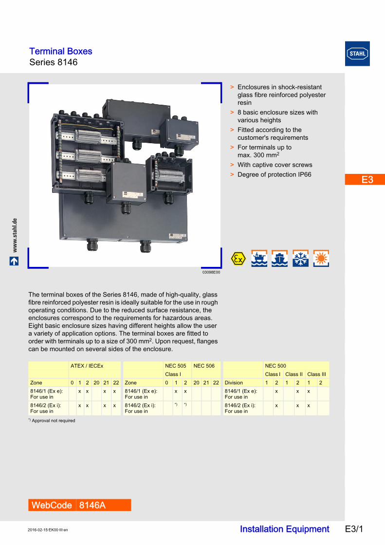
Terminal BoxesSeries 8146
ww
w.s
tah
l.d
e
Installation Equipment E3/12016-02-15·EK00·III·en
E3
E3
E3
E3
E3
E3
E3
E3
E3
E3
E3
E3
E3
E3
Series 8146 E3
03098E00
WebCode 8146A
> Enclosures in shock-resistant glass fibre reinforced polyester resin
> 8 basic enclosure sizes with various heights
> Fitted according to thecustomer's requirements
> For terminals up to max. 300 mm2
> With captive cover screws> Degree of protection IP66
The terminal boxes of the Series 8146, made of high-quality, glass fibre reinforced polyester resin is ideally suitable for the use in rough operating conditions. Due to the reduced surface resistance, the enclosures correspond to the requirements for hazardous areas. Eight basic enclosure sizes having different heights allow the user a variety of application options. The terminal boxes are fitted toorder with terminals up to a size of 300 mm2. Upon request, flanges can be mounted on several sides of the enclosure.
*) Approval not required
ATEX / IECEx NEC 505 NEC 506 NEC 500 Class I Class I Class II Class III
Zone 0 1 2 20 21 22 Zone 0 1 2 20 21 22 Division 1 2 1 2 1 28146/1 (Ex e): For use in
x x x x 8146/1 (Ex e): For use in
x x 8146/1 (Ex e): For use in
x x x
8146/2 (Ex i): For use in
x x x x 8146/2 (Ex i): For use in
*) *) 8146/2 (Ex i): For use in
x x x
Terminal BoxesSeries 8146
Installation Equipment 2016-02-15·EK00·III·enE3/2
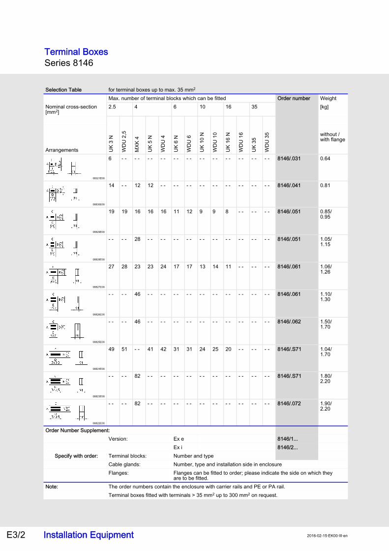
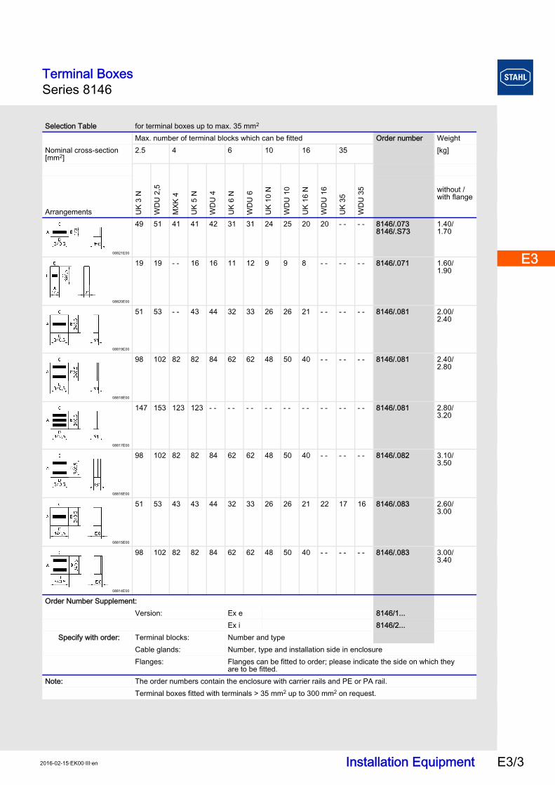
Selection Table for terminal boxes up to max. 35 mm2
Max. number of terminal blocks which can be fitted Order number WeightNominal cross-section [mm2]
2.5 4 6 10 16 35 [kg]U
K 3
N
WD
U 2
,5
MXK
4
UK
5 N
WD
U 4
UK
6 N
WD
U 6
UK
10 N
WD
U 1
0
UK
16 N
WD
U 1
6
UK
35
WD
U 3
5
Arrangements
without / with flange
06021E00
6 - - - - - - - - - - - - - - - - - - - - - - - - 8146/.031 0.64
08830E00
14 - - 12 12 - - - - - - - - - - - - - - - - - - 8146/.041 0.81
08829E00
19 19 16 16 16 11 12 9 9 8 - - - - - - 8146/.051 0.85/0.95
08828E00
- - - - 28 - - - - - - - - - - - - - - - - - - - - 8146/.051 1.05/1.15
08827E00
27 28 23 23 24 17 17 13 14 11 - - - - - - 8146/.061 1.06/1.26
08826E00
- - - - 46 - - - - - - - - - - - - - - - - - - - - 8146/.061 1.10/1.30
08825E00
- - - - 46 - - - - - - - - - - - - - - - - - - - - 8146/.062 1.50/1.70
08824E00
49 51 - - 41 42 31 31 24 25 20 - - - - - - 8146/.S71 1.04/1.70
08823E00
- - - - 82 - - - - - - - - - - - - - - - - - - - - 8146/.S71 1.80/2.20
08822E00
- - - - 82 - - - - - - - - - - - - - - - - - - - - 8146/.072 1.90/2.20
Order Number Supplement:Version: Ex e 8146/1...
Ex i 8146/2...Specify with order: Terminal blocks: Number and type
Cable glands: Number, type and installation side in enclosureFlanges: Flanges can be fitted to order; please indicate the side on which they
are to be fitted.Note: The order numbers contain the enclosure with carrier rails and PE or PA rail.
Terminal boxes fitted with terminals > 35 mm2 up to 300 mm2 on request.
Terminal BoxesSeries 8146
Installation Equipment E3/32016-02-15·EK00·III·en
E3
E3
E3
E3
E3
E3
E3
E3
E3
E3
E3
E3
E3
E3
08821E00
49 51 41 41 42 31 31 24 25 20 20 - - - - 8146/.0738146/.S73
1.40/1.70
08820E00
19 19 - - 16 16 11 12 9 9 8 - - - - - - 8146/.071 1.60/1.90
08819E00
51 53 - - 43 44 32 33 26 26 21 - - - - - - 8146/.081 2.00/2.40
08818E00
98 102 82 82 84 62 62 48 50 40 - - - - - - 8146/.081 2.40/2.80
08817E00
147 153 123 123 - - - - - - - - - - - - - - - - - - 8146/.081 2.80/3.20
08816E00
98 102 82 82 84 62 62 48 50 40 - - - - - - 8146/.082 3.10/3.50
08815E00
51 53 43 43 44 32 33 26 26 21 22 17 16 8146/.083 2.60/3.00
08814E00
98 102 82 82 84 62 62 48 50 40 - - - - - - 8146/.083 3.00/3.40
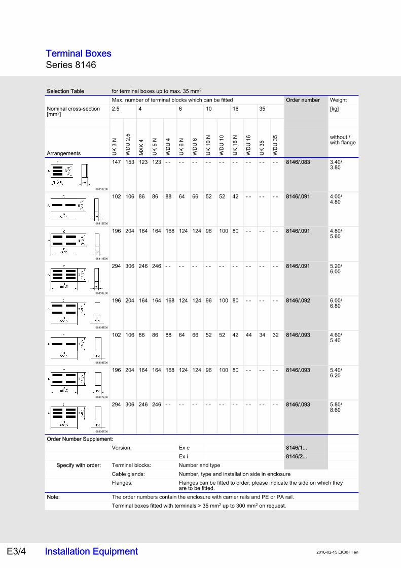
Selection Table for terminal boxes up to max. 35 mm2
Max. number of terminal blocks which can be fitted Order number WeightNominal cross-section [mm2]
2.5 4 6 10 16 35 [kg]U
K 3
N
WD
U 2
,5
MXK
4
UK
5 N
WD
U 4
UK
6 N
WD
U 6
UK
10 N
WD
U 1
0
UK
16 N
WD
U 1
6
UK
35
WD
U 3
5
Arrangements
without / with flange
Order Number Supplement:Version: Ex e 8146/1...
Ex i 8146/2...Specify with order: Terminal blocks: Number and type
Cable glands: Number, type and installation side in enclosureFlanges: Flanges can be fitted to order; please indicate the side on which they
are to be fitted.Note: The order numbers contain the enclosure with carrier rails and PE or PA rail.
Terminal boxes fitted with terminals > 35 mm2 up to 300 mm2 on request.
Terminal BoxesSeries 8146
Installation Equipment 2016-02-15·EK00·III·enE3/4
08813E00
147 153 123 123 - - - - - - - - - - - - - - - - - - 8146/.083 3.40/3.80
08812E00
102 106 86 86 88 64 66 52 52 42 - - - - - - 8146/.091 4.00/4.80
08811E00
196 204 164 164 168 124 124 96 100 80 - - - - - - 8146/.091 4.80/5.60
08810E00
294 306 246 246 - - - - - - - - - - - - - - - - - - 8146/.091 5.20/6.00
08809E00
196 204 164 164 168 124 124 96 100 80 - - - - - - 8146/.092 6.00/6.80
08808E00
102 106 86 86 88 64 66 52 52 42 44 34 32 8146/.093 4.60/5.40
08807E00
196 204 164 164 168 124 124 96 100 80 - - - - - - 8146/.093 5.40/6.20
08806E00
294 306 246 246 - - - - - - - - - - - - - - - - - - 8146/.093 5.80/8.60
Selection Table for terminal boxes up to max. 35 mm2
Max. number of terminal blocks which can be fitted Order number WeightNominal cross-section [mm2]
2.5 4 6 10 16 35 [kg]U
K 3
N
WD
U 2
,5
MXK
4
UK
5 N
WD
U 4
UK
6 N
WD
U 6
UK
10 N
WD
U 1
0
UK
16 N
WD
U 1
6
UK
35
WD
U 3
5
Arrangements
without / with flange
Order Number Supplement:Version: Ex e 8146/1...
Ex i 8146/2...Specify with order: Terminal blocks: Number and type
Cable glands: Number, type and installation side in enclosureFlanges: Flanges can be fitted to order; please indicate the side on which they
are to be fitted.Note: The order numbers contain the enclosure with carrier rails and PE or PA rail.
Terminal boxes fitted with terminals > 35 mm2 up to 300 mm2 on request.
Terminal BoxesSeries 8146
Installation Equipment E3/52016-02-15·EK00·III·en
E3
E3
E3
E3
E3
E3
E3
E3
E3
E3
E3
E3
E3
E3
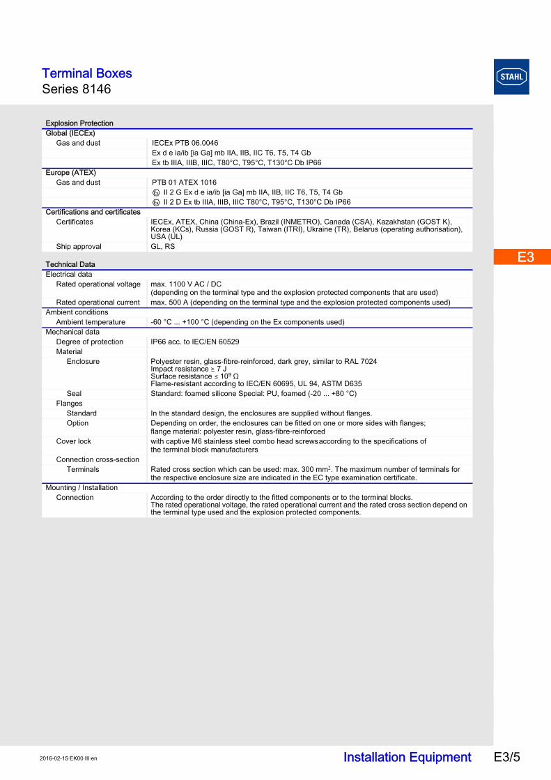
Explosion ProtectionGlobal (IECEx)
Gas and dust IECEx PTB 06.0046Ex d e ia/ib [ia Ga] mb IIA, IIB, IIC T6, T5, T4 GbEx tb IIIA, IIIB, IIIC, T80°C, T95°C, T130°C Db IP66
Europe (ATEX)Gas and dust PTB 01 ATEX 1016
E II 2 G Ex d e ia/ib [ia Ga] mb IIA, IIB, IIC T6, T5, T4 GbE II 2 D Ex tb IIIA, IIIB, IIIC T80°C, T95°C, T130°C Db IP66
Certifications and certificatesCertificates IECEx, ATEX, China (China-Ex), Brazil (INMETRO), Canada (CSA), Kazakhstan (GOST K),
Korea (KCs), Russia (GOST R), Taiwan (ITRI), Ukraine (TR), Belarus (operating authorisation), USA (UL)
Ship approval GL, RS
Technical DataElectrical data
Rated operational voltage max. 1100 V AC / DC(depending on the terminal type and the explosion protected components that are used)
Rated operational current max. 500 A (depending on the terminal type and the explosion protected components used)Ambient conditions
Ambient temperature -60 °C ... +100 °C (depending on the Ex components used)Mechanical data
Degree of protection IP66 acc. to IEC/EN 60529Material
Enclosure Polyester resin, glass-fibre-reinforced, dark grey, similar to RAL 7024 Impact resistance ) 7 J Surface resistance ( 109 O Flame-resistant according to IEC/EN 60695, UL 94, ASTM D635
Seal Standard: foamed silicone Special: PU, foamed (-20 ... +80 °C)Flanges
Standard In the standard design, the enclosures are supplied without flanges.Option Depending on order, the enclosures can be fitted on one or more sides with flanges;
flange material: polyester resin, glass-fibre-reinforcedCover lock with captive M6 stainless steel combo head screwsaccording to the specifications of
the terminal block manufacturersConnection cross-section
Terminals Rated cross section which can be used: max. 300 mm. The maximum number of terminals for the respective enclosure size are indicated in the EC type examination certificate.
Mounting / InstallationConnection According to the order directly to the fitted components or to the terminal blocks.
The rated operational voltage, the rated operational current and the rated cross section depend on the terminal type used and the explosion protected components.
Terminal BoxesSeries 8146
Installation Equipment 2016-02-15·EK00·III·enE3/6
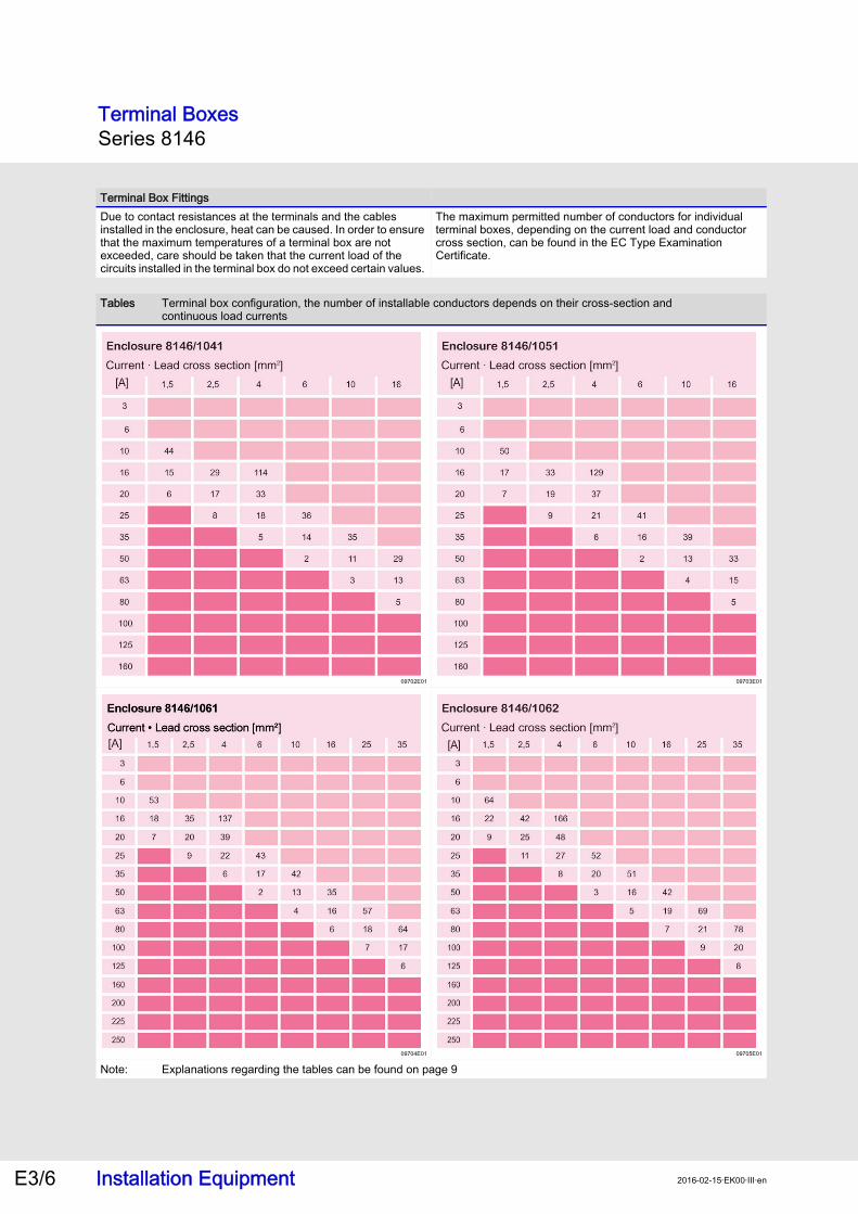
Terminal Box FittingsDue to contact resistances at the terminals and the cables installed in the enclosure, heat can be caused. In order to ensure that the maximum temperatures of a terminal box are not exceeded, care should be taken that the current load of the circuits installed in the terminal box do not exceed certain values.
The maximum permitted number of conductors for individual terminal boxes, depending on the current load and conductor cross section, can be found in the EC Type Examination Certificate.
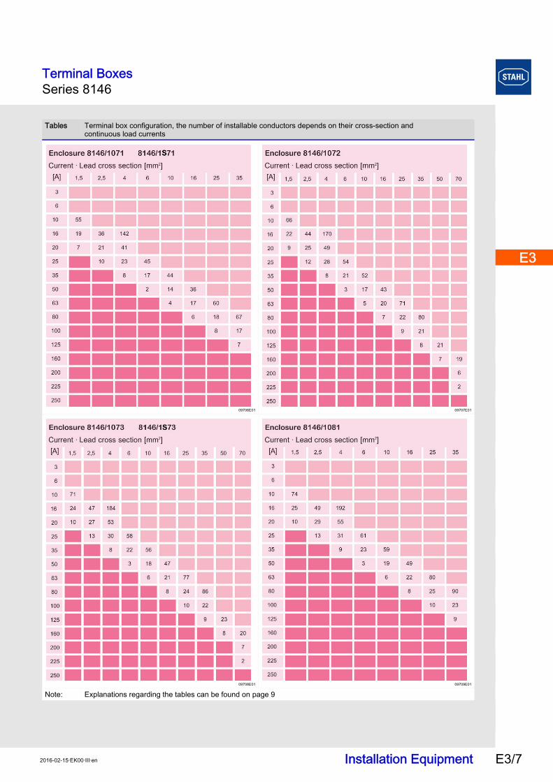
Tables Terminal box configuration, the number of installable conductors depends on their cross-section andcontinuous load currents
09702E01 09703E01
09704E01 09705E01
Note: Explanations regarding the tables can be found on page 9
Terminal BoxesSeries 8146
Installation Equipment E3/72016-02-15·EK00·III·en
E3
E3
E3
E3
E3
E3
E3
E3
E3
E3
E3
E3
E3
E3
09706E01 09707E01
09708E01 09709E01
Note: Explanations regarding the tables can be found on page 9
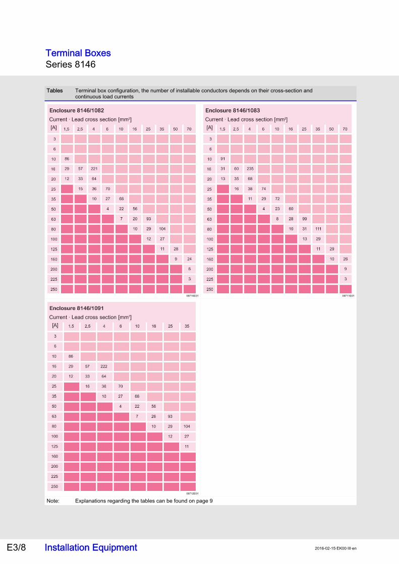
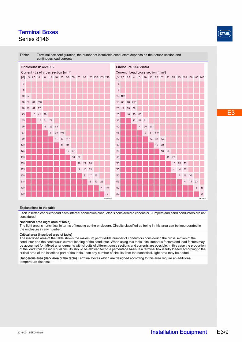
Tables Terminal box configuration, the number of installable conductors depends on their cross-section andcontinuous load currents
Terminal BoxesSeries 8146
Installation Equipment 2016-02-15·EK00·III·enE3/8
09710E01 09711E01
09712E01
Note: Explanations regarding the tables can be found on page 9
Tables Terminal box configuration, the number of installable conductors depends on their cross-section andcontinuous load currents
Terminal BoxesSeries 8146
Installation Equipment E3/92016-02-15·EK00·III·en
E3
E3
E3
E3
E3
E3
E3
E3
E3
E3
E3
E3
E3
E3
09713E00 09714E01
Explanations to the tableEach inserted conductor and each internal connection conductor is considered a conductor. Jumpers and earth conductors are not considered.Noncritical area (light area of table)The light area is noncritical in terms of heating up the enclosure. Circuits classified as being in this area can be incorporated inthe enclosure in any number.Critical area (inscribed area of table)The inscribed area of the table shows the maximum permissible number of conductors considering the cross section of the conductor and the continuous current loading of the conductor. When using this table, simultaneous factors and load factors may be accounted for. Mixed arrangements with circuits of different cross sections and currents are possible. In this case the proportion of the load from the individual circuits should be allowed for on a percentage basis. If a terminal box is fully loaded according to the critical area of the inscribed part of the table, then any number of circuits from the noncritical, light area may be added. Dangerous area (dark area of the table) Terminal boxes which are designed according to this area require an additional temperature-rise test.
Tables Terminal box configuration, the number of installable conductors depends on their cross-section andcontinuous load currents
Terminal BoxesSeries 8146
Installation Equipment 2016-02-15·EK00·III·enE3/10
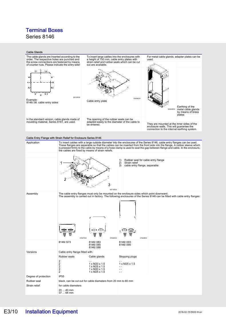
Cable GlandsThe cable glands are inserted according to the order. The respective holes are punched and the screw connections are fastened by means of counter nuts. Please indicate the entry side!
To insert large cables into the enclosures with a height of 150 mm, cable entry plates with strain relief and rubber seals which can be cut out are available.
For metal cable glands, adapter plates can be used.
05380E00
06102E00
Example: 8146/.08. cable entry sides
05409E00
Cable entry plate
Earthing of the metal cable glands by means of brass plates
In the standard version, cable glands made of moulding material, Series 8161, are used.
The opening of the rubber seals can be adapted easily to the diameter of the cable to be entered. They are mounted at the inner sides of the
enclosure walls. This will guarantee theconnection to the internal earthing system.
Cable Entry Flange with Strain Relief for Enclosure Series 8146Application To insert cables with a large outside diameter into the enclosures of the Series 8146, cable entry flanges can be used.
These flanges are separable so that the cables can be inserted from the front side into the flange. A rubber sleeve which is pressed firmly to the cable by means of a hose clamp is used to seal the gap between flange and cable. In the enclosure, the cables are fixed by means of strain reliefs.
09715E00
1)2)3)
Rubber seal for cable entry flangeStrain relief cable entry flange, separable
Assembly The cable entry flanges must only be mounted on the enclosure sides which point downward. The assembly is carried out in factory. The following enclosures of the Series 8146 can be fitted with cable entry flanges:
07947E00 07948E00 07949E00
8146/.S73 8146/.0838146/.0858146/.086
8146/.0938146/.095
Versions Cable entry flange fitted with:Rubber seals Cable glands Stopping plugs22222
- -1 x M20 x 1.51 x M25 x 1.51 x M20 x 1.51 x M25 x 1.5
- -1 x M25 x 1.5- -- -- -
Degree of protection IP55Rubber seal black, can be cut out for cable diameters from 20 mm to 60 mmStrain relief for cable diameters
20 ... 40 mm37 ... 64 mm
Terminal BoxesSeries 8146
Installation Equipment E3/112016-02-15·EK00·III·en
E3
E3
E3
E3
E3
E3
E3
E3
E3
E3
E3
E3
E3
E3
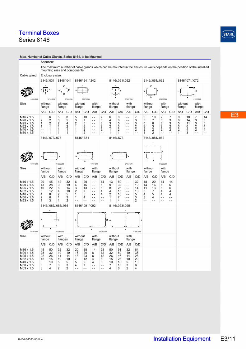
Max. Number of Cable Glands, Series 8161, to be MountedAttention:The maximum number of cable glands which can be mounted in the enclosure walls depends on the position of the installed mounting rails and components.
Cable gland Enclosure size8146/.031 8146/.041 8146/.241/.242 8146/.051/.052 8146/.061/.062 8146/.071/.072
05864E00 07959E00 07958E00 03876E00 07957E00 07956E00 07955E00
Size without flange
withoutflange
withoutflange
withflange
withoutflange
withflange
withoutflange
withflange
withoutflange
withflange
A/B C/D A/B C/D A/B C/D A/B C/D A/B C/D A/B C/D A/B C/D A/B C/D A/B C/D A/B C/DM16 x 1.5M20 x 1.5M25 x 1.5M32 x 1.5M40 x 1.5M50 x 1.5
3211- -- -
622111
532111
854211
532111
1076322
- -- -- -- -- -- -
73322- -
643211
865321
- -- -- -- -- -- -
73322- -
865321
1076322
73322- -
73322- -
865321
181411643
73322- -
146644- -
8146/.073/.075 8146/.S71 8146/.S73 8146/.081/.082
05864E00 07955E00 07954E00 07954E00 07953E00
Size withoutflange
withflange
withoutflange
withflange
withoutflange
withflange
withoutflange
withflange
A/B C/D A/B C/D A/B C/D A/B C/D A/B C/D A/B C/D A/B C/D A/B C/DM16 x 1.5M20 x 1.5M25 x 1.5M32 x 1.5M40 x 1.5M50 x 1.5M63 x 1.5
2013106421
45282212863
12964211
32191410532
643211- -
201613754- -
- -- -- -- -- -- -- -
146644- -- -
13984211
503226151074
- -- -- -- -- -- -- -
32191410532
181411643- -
201613754- -
146644- -- -
146644- -- -
8146/.083/.085/.086 8146/.091/.092 8146/.093/.095
05864E00 07953E00 07952E00 07952E00
Size without flange
withflanges
withoutflange
withflange
withoutflange
withflange
A/B C/D A/B C/D A/B C/D A/B C/D A/B C/D A/B C/DM16 x 1.5M20 x 1.5M25 x 1.5M32 x 1.5M40 x 1.5M50 x 1.5M63 x 1.5
45282212863
503226151074
32191410532
32191410532
201613754- -
3820231297- -
146644- -- -
28121288- -- -
503226151074
9160462618136
32191410532
643828201064
Terminal BoxesSeries 8146
Installation Equipment 2016-02-15·EK00·III·enE3/12
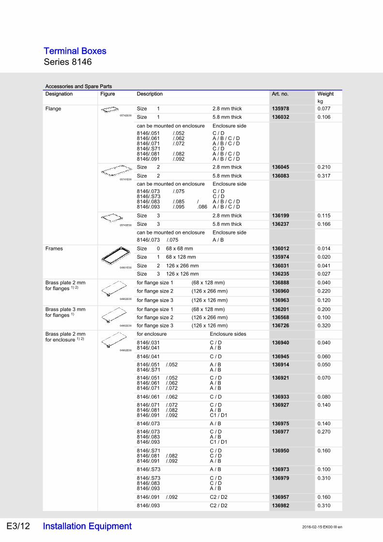
Accessories and Spare PartsDesignation Figure Description Art. no. Weight
kgFlange
05742E00
135978 0.077136032 0.106
05741E00
136045 0.210136083 0.317
05743E00
136199 0.115136237 0.166
Frames
04901E00
136012 0.014135974 0.020136031 0.041136235 0.027
Brass plate 2 mmfor flanges 1) 2)
04902E00
136888 0.040136960 0.220
136963 0.120
Brass plate 3 mmfor flanges 1)
04902E00
136201 0.200136568 0.100136726 0.320
Brass plate 2 mm for enclosure 1) 2)
04902E00
136940 0.040
136945 0.060136914 0.050
136921 0.070
136933 0.080136927 0.140
136975 0.140136977 0.270
136950 0.160
136973 0.100136979 0.310
136957 0.160136982 0.310
Size 1 2.8 mm thickSize 1 5.8 mm thickcan be mounted on enclosure Enclosure side8146/.0518146/.0618146/.0718146/.S718146/.0818146/.091
/.052/.062/.072
/.082/.092
C / DA / B / C / DA / B / C / DC / DA / B / C / DA / B / C / D
Size 2 2.8 mm thickSize 2 5.8 mm thickcan be mounted on enclosure Enclosure side8146/.0738146/.S738146/.0838146/.093
/.075
/.085/.095
/.086
C / DC / DA / B / C / DA / B / C / D
Size 3 2.8 mm thickSize 3 5.8 mm thickcan be mounted on enclosure Enclosure side8146/.073 /.075 A / BSize 0 68 x 68 mmSize 1 68 x 128 mmSize 2 126 x 266 mmSize 3 126 x 126 mmfor flange size 1 (68 x 128 mm)for flange size 2 (126 x 266 mm)
for flange size 3 (126 x 126 mm)
for flange size 1 (68 x 128 mm)for flange size 2 (126 x 266 mm)for flange size 3 (126 x 126 mm)for enclosure Enclosure sides8146/.0318146/.041
C / DA / B
8146/.041 C / D8146/.0518146/.S71
/.052 A / BA / B
8146/.0518146/.0618146/.071
/.052/.062/.072
C / DA / BA / B
8146/.061 /.062 C / D8146/.0718146/.0818146/.091
/.072/.082/.092
C / DA / BC1 / D1
8146/.073 A / B8146/.0738146/.0838146/.093
C / DA / BC1 / D1
8146/.S718146/.0818146/.091
/.082/.092
C / DC / DA / B
8146/.S73 A / B8146/.S738146/.0838146/.093
C / DC / DA / B
8146/.091 /.092 C2 / D28146/.093 C2 / D2
Terminal BoxesSeries 8146
Installation Equipment E3/132016-02-15·EK00·III·en
E3
E3
E3
E3
E3
E3
E3
E3
E3
E3
E3
E3
E3
E3
Brass plate 3 mmfor enclosure 1)
04902E00
136395 0.100
136403 0.160136635 0.150136240 0.140
136283 0.200
136430 0.560
136374 0.200136313 0.400
136451 0.560
136616 0.410136631 0.770136621 0.810
136544 0.460
136611 0.265136626 0.880
Serrated lock washer
09717E00
110706 0.009110707 0.007110708 0.021110709 0.040110710 0.060
Accessories and Spare PartsDesignation Figure Description Art. no. Weight
kgfor enclosure Enclosure sides8146/.0318146/.041
C / DA / B
8146/.041 C / D8146/.041 C / D8146/.0518146/.S71
/.052 A / BA / B
8146/.0518146/.0618146/.071
/.052/.062/.072
C / DA / BA / B
8146/.0518146/.0618146/.071
/.052/.062/.072
C / DA / BA / B
8146/.061 /.062 C / D8146/.0718146/.0818146/.091
/.072/.082/.092
C / DA / BC 1 / D1
8146/.0718146/.081
/.072/.082
C / DA / B
8146/.073 A / B8146/.073 C / D8146/.0738146/.0838146/.093
C / DA / BC1 / D1
8146/.S718146/.0818146/.091
/.082/.092
C / DC / DA / B
8146/.S73 A / B8146/.S738146/.0838146/.093
C / DC / DA / B
for M25 1 pcs.for M32 1 pcs.for M40 1 pcs.for M50 1 pcs.for M63 1 pcs.
1) For earthing metal gland parts when used in moulded plastic enclosures and plastic flanges
2) - If the connecting cable is equipped with an armour which is larger than 6 mm2 and which is used as earthing conductor, a brass plate with a thickness of 3 mm must be used.
- Due to the higher strain on the enclosure wall, the 3 mm brass plate has also to be used forlarge bell mounted glands.
Terminal BoxesSeries 8146
Installation Equipment 2016-02-15·EK00·III·enE3/14
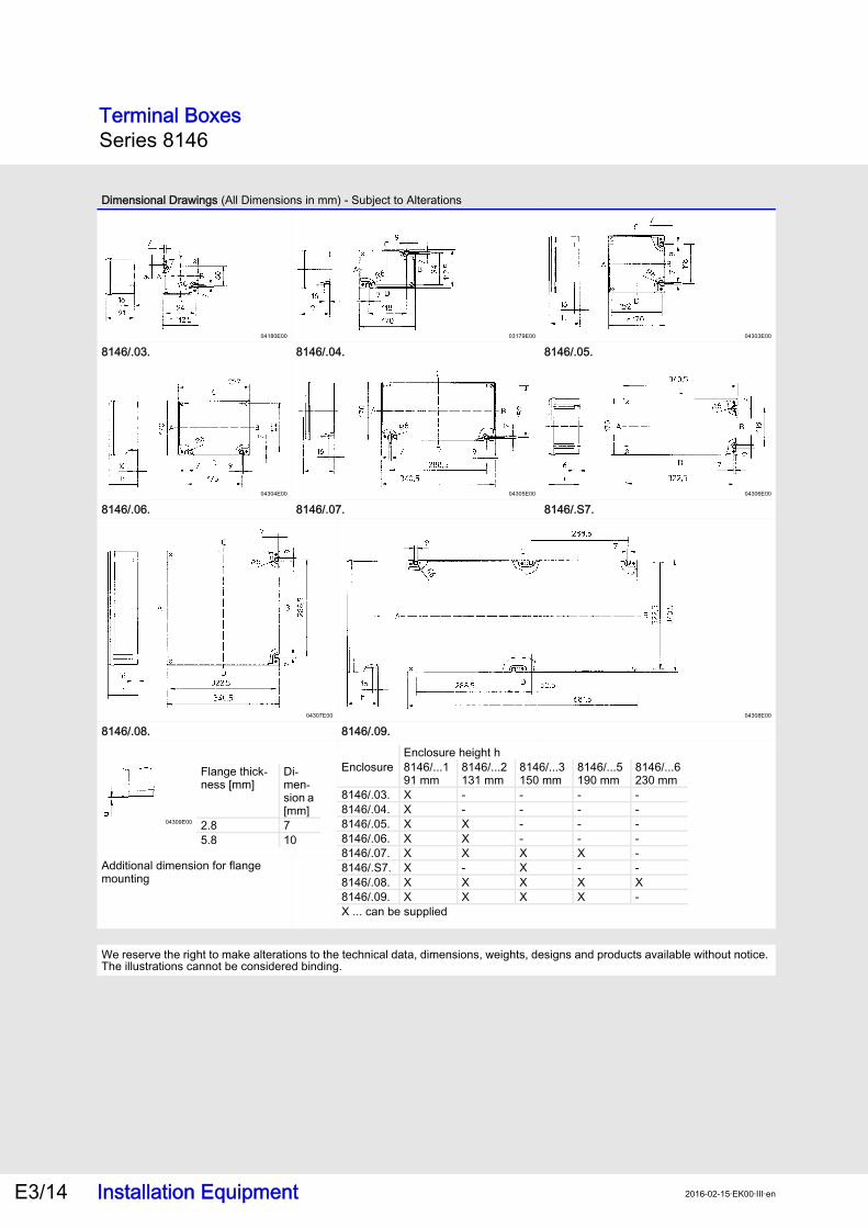
Dimensional Drawings (All Dimensions in mm) - Subject to Alterations
04180E00 03179E00 04303E00
8146/.03. 8146/.04. 8146/.05.
04304E00 04305E00 04306E00
8146/.06. 8146/.07. 8146/.S7.
04307E00 04308E00
8146/.08. 8146/.09.
04309E00
Additional dimension for flange mounting
We reserve the right to make alterations to the technical data, dimensions, weights, designs and products available without notice. The illustrations cannot be considered binding.
Enclosure height hEnclosure 8146/...1
91 mm8146/...2131 mm
8146/...3150 mm
8146/...5190 mm
8146/...6230 mm
8146/.03. X - - - -8146/.04. X - - - -8146/.05. X X - - -8146/.06. X X - - -8146/.07. X X X X -8146/.S7. X - X - -8146/.08. X X X X X8146/.09. X X X X -X ... can be supplied
Flange thick-ness [mm]
Di-men-sion a [mm]
2.8 75.8 10