Embed Size (px)
Citation preview
Document 90-00066 Algo Communication Products Ltd (604) 454-3792 2014-02-20 4500 Beedie St Burnaby BC Canada V5J 5L2 [email protected] Page 1 www.algosolutions.com
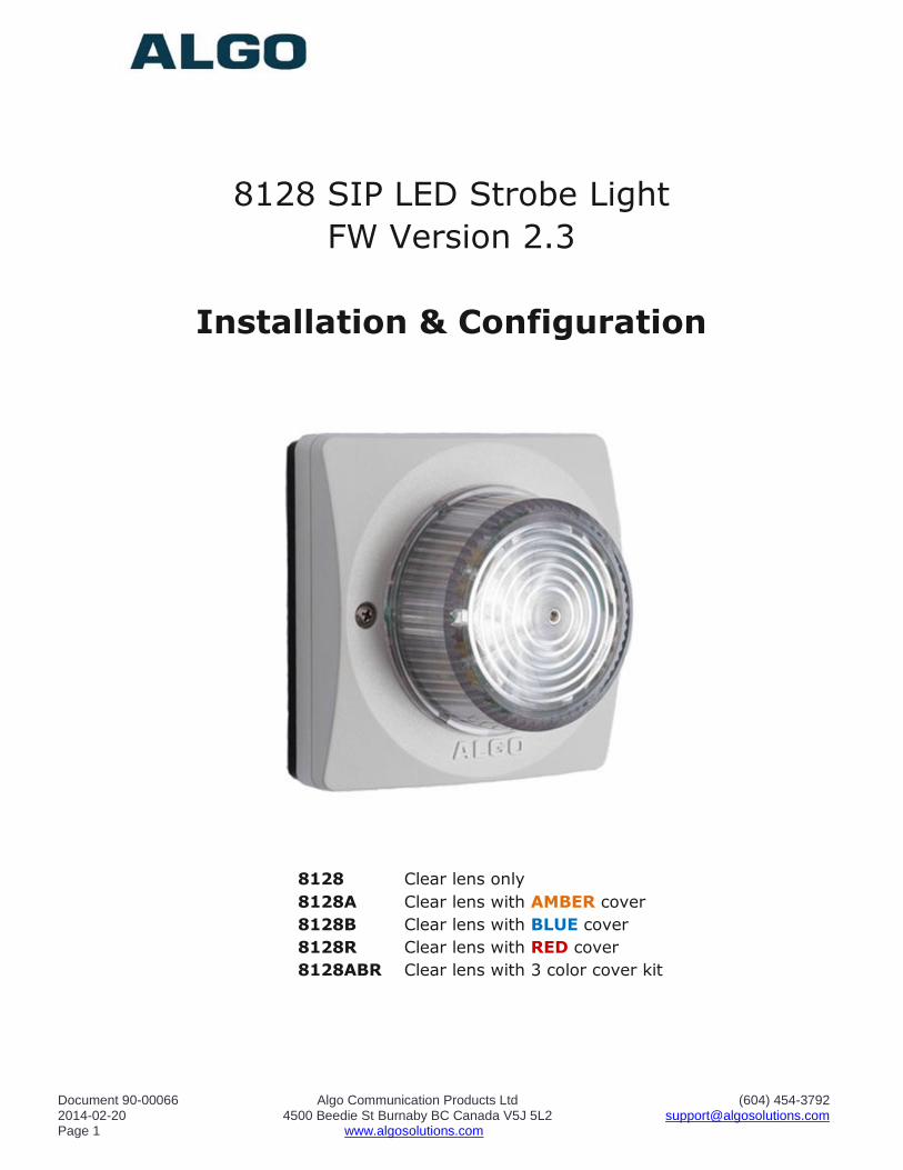
8128 SIP LED Strobe Light
FW Version 2.3
Installation & Configuration
8128 Clear lens only
8128A Clear lens with AMBER cover
8128B Clear lens with BLUE cover
8128R Clear lens with RED cover
8128ABR Clear lens with 3 color cover kit
Document 90-00066 Algo Communication Products Ltd (604) 454-3792 2014-02-20 4500 Beedie St Burnaby BC Canada V5J 5L2 [email protected] Page 2 www.algosolutions.com
CONTENTS
Important Safety Information ................................................................................. 4
About the 8128 Strobe ............................................................................................ 5
Common Applications .............................................................................................. 5
Quick Start .............................................................................................................. 6
What's Included ...................................................................................................... 7
Wiring Connections ................................................................................................. 8
Network Connection ................................................................................................. 8
Terminal Block Relay In ............................................................................................ 8
Terminal Block Relay Out .......................................................................................... 8
Terminal Block Reset ................................................................................................ 8
Web Interface Login ................................................................................................ 9
Basic Settings Tab - SIP ........................................................................................ 10
SIP Domain (Proxy Server) ..................................................................................... 10
SIP Extension ........................................................................................................ 10
Authentication ID ................................................................................................... 10
Authentication Password ......................................................................................... 10
Monitoring Mode .................................................................................................... 11
Activating 8128 Strobe Using Subscribe/Notify .......................................................... 11
Basic Settings Tab - Features ................................................................................ 12
Flash Patterns ....................................................................................................... 12
Flash Pattern Test .................................................................................................. 13
Cadence ............................................................................................................... 14
Relay Input Detection Mode .................................................................................... 14
Relay Input Action ................................................................................................. 14
Relay Output Mode ................................................................................................ 14
Multicast Overview ................................................................................................ 14
Multicast IP Addresses .......................................................................................... 15
Basic Settings Tab - Multicast Master Settings ...................................................... 16
Multicast Mode (Master Selected)............................................................................. 16
Master Zone .......................................................................................................... 16
Send Flash Pattern ................................................................................................. 17
Send 8180-Compatible Control Signal ...................................................................... 17
Zone Definitions .................................................................................................... 17
Synchronization ..................................................................................................... 17
Basic Settings - Multicast Slave Settings ............................................................... 18
Multicast Mode (Slave Selected) .............................................................................. 18
Slave Zones .......................................................................................................... 18
Zone Definitions .................................................................................................... 19
Advanced Settings - SIP ........................................................................................ 19
Outbound Proxy ..................................................................................................... 19
STUN Server ......................................................................................................... 19
Register Period (seconds) ....................................................................................... 20
Keep-alive Method ................................................................................................. 20
Document 90-00066 Algo Communication Products Ltd (604) 454-3792 2014-02-20 4500 Beedie St Burnaby BC Canada V5J 5L2 [email protected] Page 3 www.algosolutions.com
Server Redundancy Feature .................................................................................... 20
Backup Server #1 .................................................................................................. 20
Backup Server #2 .................................................................................................. 20
Polling Intervals (seconds) ...................................................................................... 20
Poll Active Server................................................................................................... 20
Automatic Failback ................................................................................................. 21
Polling Method ....................................................................................................... 21
Advanced Settings - Network ................................................................................ 21
Protocol ................................................................................................................ 22
VLAN Mode ........................................................................................................... 22
VLAN ID ............................................................................................................... 22
VLAN Priority ......................................................................................................... 22
Differentiated Services (6-bit DSCP value) ................................................................ 22
DHCP Timeout ....................................................................................................... 23
Advanced Settings - Administration ...................................................................... 23
Password .............................................................................................................. 23
Confirmation ......................................................................................................... 24
Device Name ......................................................................................................... 24
NTP Time Server .................................................................................................... 24
Introduction Section on Status Page ......................................................................... 24
Log Level .............................................................................................................. 24
Log Size ............................................................................................................... 24
Log Method ........................................................................................................... 24
Log Server ............................................................................................................ 24
Hardware Watchdog ............................................................................................... 24
SNMP Support (v1 get only) .................................................................................... 24
Advanced Settings - Provisioning .......................................................................... 25
MD5 Checksum ..................................................................................................... 26
Generating a generic configuration file ..................................................................... 26
Generating a specific configuration file ..................................................................... 27
System - Maintenance ........................................................................................... 27
Download Configuration File .................................................................................... 28
Restore Configuration File ....................................................................................... 28
Restore Configuration to Defaults ............................................................................ 28
Reboot the Device.................................................................................................. 28
Firmware Image .................................................................................................... 28
MD5 Checksum ..................................................................................................... 28
Upgrade 8128 Strobe Firmware ............................................................................... 28
System - Network Logging .................................................................................... 29
Optional Colored Lens Cover .................................................................................. 29
Specifications: ....................................................................................................... 30
FCC Compliance ..................................................................................................... 31
Document 90-00066 Algo Communication Products Ltd (604) 454-3792 2014-02-20 4500 Beedie St Burnaby BC Canada V5J 5L2 [email protected] Page 4 www.algosolutions.com
Important Safety Information
The 8128 Strobe is NOT INTENDED FOR FIRE ALARM
SIGNALLING APPLICATIONS.
The 8128 Strobe is intended for informative signaling in conjunction
with unified communication systems. The 8128 Strobe is suitable for
OSHA and ADA compliance when properly located and configured.
DO NOT LOOK DIRECTLY at the 8128 Strobe while operating
in close proximity as vision may be affected. The LEDs in the 8128
Strobe are classified according to the IEC 62471-2006 standard as
"RG-2" for risk group 2. This is defined as "Moderate risk. Does not
pose a hazard due to aversion response to bright light or thermal
discomfort".
PHOTO-SENSITIVITY in some people with epilepsy can trigger
seizures from flashing or flickering lights. It is possible that some flash patterns of the 8128 Strobe could trigger a seizure for some individuals
under some conditions. High intensity patterns should only be selected if necessary for the 8128 Strobe to be effective.
Wet or Outdoor Environments
The 8128 LED Strobe is intended for indoor or outdoor locations and
may be subjected to spray or weather provided the rear wiring cavity is properly sealed to prevent water ingress.
Gaskets included with the 8128 LED Strobe may be effective against
water ingress on some, but not all surfaces in which case additional
protective measures must be taken such as a perimeter sealant.
CAT5 or CAT6 connection wiring to an IEEE 802.3af compliant
network PoE switch must not leave the building perimeter without adequate lightning protection.
Relay input and output connections must not leave the building
perimeter without adequate lightning protection.
Document 90-00066 Algo Communication Products Ltd (604) 454-3792 2014-02-20 4500 Beedie St Burnaby BC Canada V5J 5L2 [email protected] Page 5 www.algosolutions.com
About the 8128 Strobe
The 8128 Strobe flash intensity can be chosen to suit the application and environment. There are non-flashing patterns for passive, gentle notification, and aggressive patterns for maximum conspicuity in busy
environments
The 8128 Strobe is typically wall or ceiling mounted. The eight efficient and powerful LEDs cast light 360 x 180 degrees with some light illuminating the surface surrounding the 8128 Strobe for additional visibility. Light output is
equally intense in every direction unless a directional pattern is chosen.
The 8128 Strobe can be activated by:
SIP Ring
SIP Message Waiting SIP In-Use (Subscribe Notify)
Dry contact closure input Multicasting
If multiple 8128 Strobes are required, the multicasting feature requires only one of the 8128 Strobes to be activated by an input. The activated
8128 Strobe can simultaneously multicast as a master to activate the other 8128 Strobes configured as slaves.
The 8128 Strobe is configured from its web interface using a browser such as Google Chrome, Firefox, or Internet Explorer (other than IE 9).
Common Applications
Telephone ring notification in noisy environments
Silent ring notification in quiet environments
Call center ACD queue threshold alert (by ringing)
In-use (off-hook, on-air) notification for co-workers
Message waiting notification
OSHA safety compliance
ADA compliance
Door open visual alarm
Voice paging pre-announce
Security notification
Document 90-00066 Algo Communication Products Ltd (604) 454-3792 2014-02-20 4500 Beedie St Burnaby BC Canada V5J 5L2 [email protected] Page 6 www.algosolutions.com
Quick Start
1. Connect the 8128 Strobe to a 802.3af PoE network using the RJ45
jack in the back recess of the housing.
2. Allow the 8128 Strobe time to boot, about 30 seconds. During boot
up the Strobe will turn on each LED individually as a test and then all on at low intensity until booting is completed.
3. If there is no DHCP server found the 8128 Strobe will default to the
static IP address 192.168.1.111. Most often however the 8128 Strobe will be assigned an IP address. To determine the IP address for the 8128 Strobe download the Algo locator tool to find Algo
devices on your network: www.algosolutions.com/locator
4. Access the 8128 Strobe web page by entering the IP address into a browser and login using algo as the default password.
5. Enter the IP address for the SIP server into the SIP Domain field under the BASIC SETTINGS - SIP tab.
6. Enter the SIP extension and password information.
7. Test by dialing the SIP extension for the Strobe . The Strobe should flash in response to ring (the 8128 Strobe will not answer a ring
event).
Installation & Mounting
The 8128 Strobe can be wall or ceiling mounted. Concealed wiring may
enter from the wall into the wiring cavity. Alternatively, surface wiring may enter through a channel from the bottom edge. The channel is intended for
cabling 0.2" or 5mm in diameter and is intentionally snug to protect against moisture ingress.
The 8128 Strobe can be mounted in any orientation but both the bracket and housing identify TOP. This keeps the bracket wiring channel on the
bottom and the RJ45 jack on the top side.
Document 90-00066 Algo Communication Products Ltd (604) 454-3792 2014-02-20 4500 Beedie St Burnaby BC Canada V5J 5L2 [email protected] Page 7 www.algosolutions.com
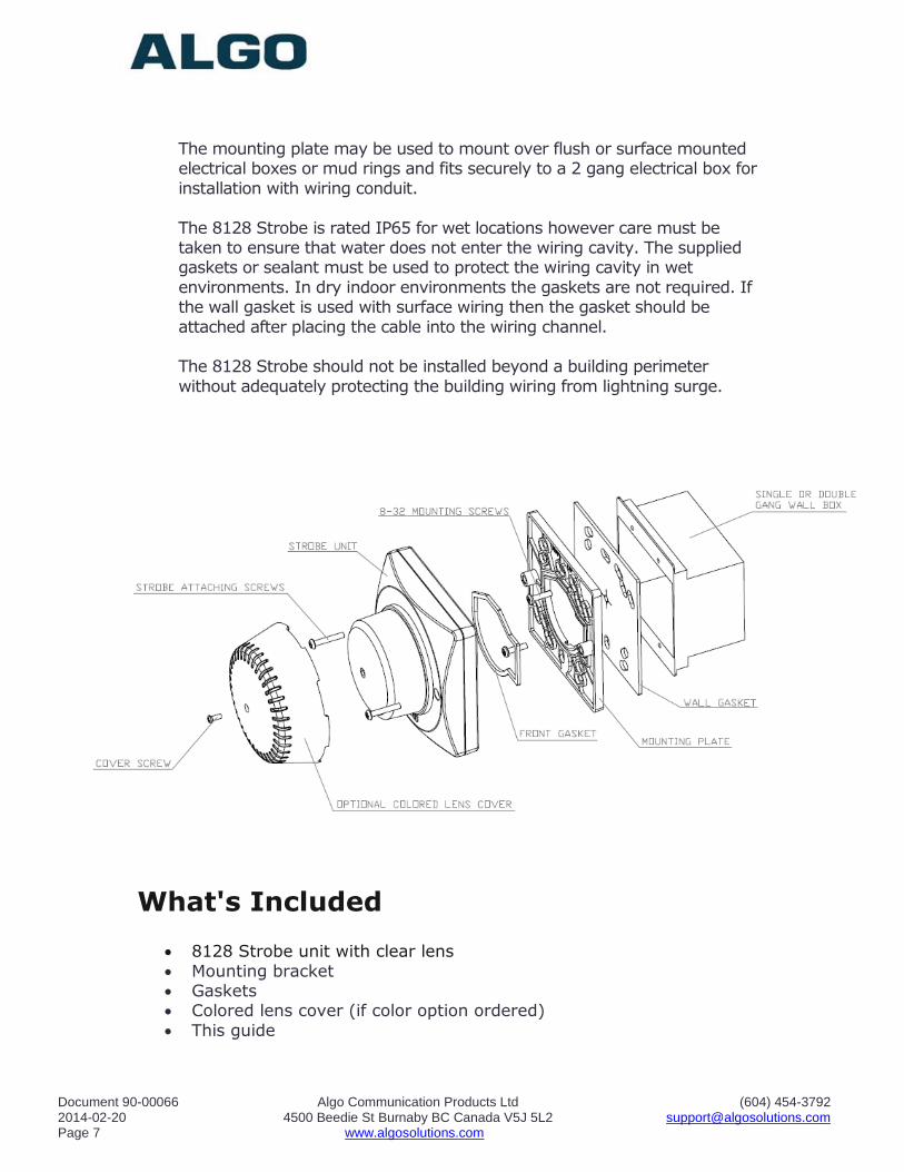
The mounting plate may be used to mount over flush or surface mounted electrical boxes or mud rings and fits securely to a 2 gang electrical box for
installation with wiring conduit.
The 8128 Strobe is rated IP65 for wet locations however care must be taken to ensure that water does not enter the wiring cavity. The supplied gaskets or sealant must be used to protect the wiring cavity in wet
environments. In dry indoor environments the gaskets are not required. If the wall gasket is used with surface wiring then the gasket should be
attached after placing the cable into the wiring channel. The 8128 Strobe should not be installed beyond a building perimeter
without adequately protecting the building wiring from lightning surge.
What's Included
8128 Strobe unit with clear lens
Mounting bracket Gaskets Colored lens cover (if color option ordered)
This guide
Document 90-00066 Algo Communication Products Ltd (604) 454-3792 2014-02-20 4500 Beedie St Burnaby BC Canada V5J 5L2 [email protected] Page 8 www.algosolutions.com
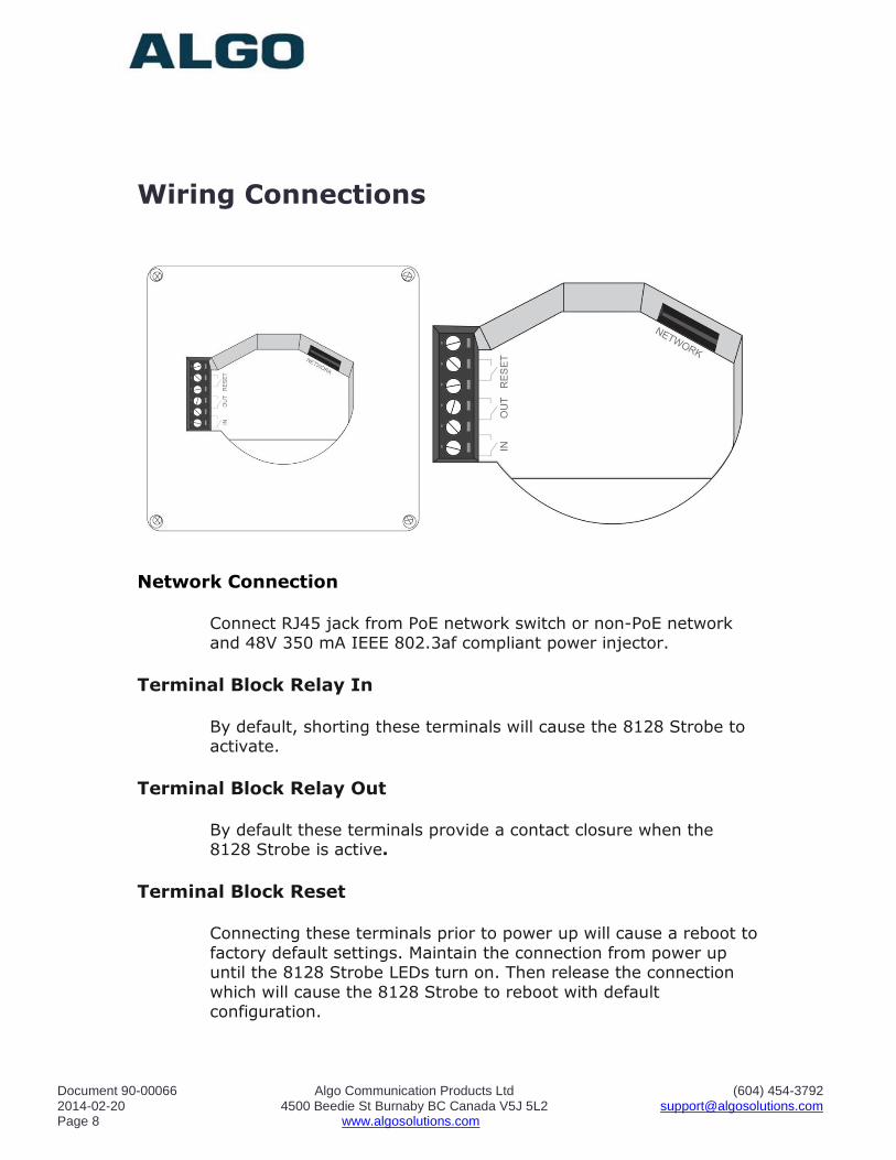
Wiring Connections
Network Connection
Connect RJ45 jack from PoE network switch or non-PoE network
and 48V 350 mA IEEE 802.3af compliant power injector.
Terminal Block Relay In
By default, shorting these terminals will cause the 8128 Strobe to
activate.
Terminal Block Relay Out By default these terminals provide a contact closure when the
8128 Strobe is active.
Terminal Block Reset
Connecting these terminals prior to power up will cause a reboot to
factory default settings. Maintain the connection from power up until the 8128 Strobe LEDs turn on. Then release the connection
which will cause the 8128 Strobe to reboot with default configuration.
Document 90-00066 Algo Communication Products Ltd (604) 454-3792 2014-02-20 4500 Beedie St Burnaby BC Canada V5J 5L2 [email protected] Page 9 www.algosolutions.com
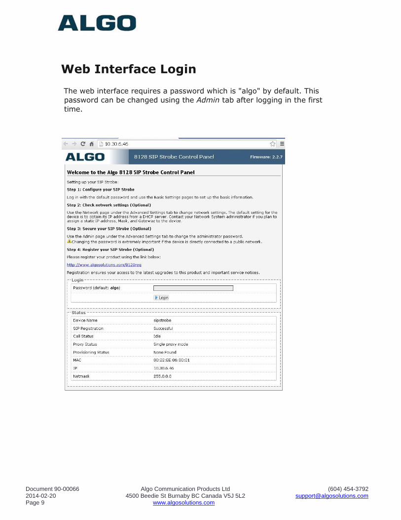
Web Interface Login
The web interface requires a password which is "algo" by default. This
password can be changed using the Admin tab after logging in the first
time.
Document 90-00066 Algo Communication Products Ltd (604) 454-3792 2014-02-20 4500 Beedie St Burnaby BC Canada V5J 5L2 [email protected] Page 10 www.algosolutions.com
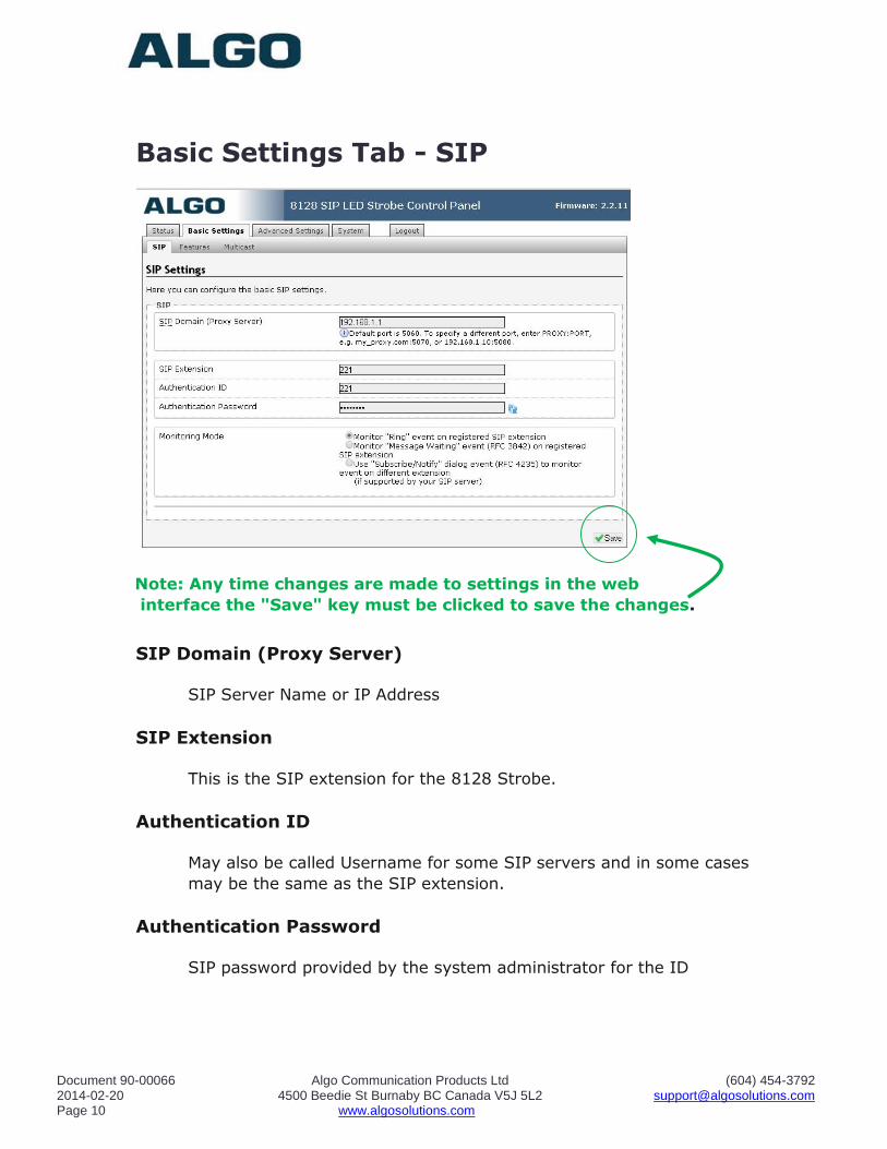
Basic Settings Tab - SIP
Note: Any time changes are made to settings in the web
interface the "Save" key must be clicked to save the changes.
SIP Domain (Proxy Server)
SIP Server Name or IP Address
SIP Extension
This is the SIP extension for the 8128 Strobe.
Authentication ID
May also be called Username for some SIP servers and in some cases
may be the same as the SIP extension.
Authentication Password
SIP password provided by the system administrator for the ID
Document 90-00066 Algo Communication Products Ltd (604) 454-3792 2014-02-20 4500 Beedie St Burnaby BC Canada V5J 5L2 [email protected] Page 11 www.algosolutions.com
Monitoring Mode
There are five ways in which the 8128 Strobe can be activated.
Dry contact input or multicast does not require registration with a SIP
server and is discussed elsewhere in this guide.
The monitoring mode selects whether SIP activation is by ring,
message waiting, or subscribe/notify as described below.
Activating 8128 Strobe from SIP Ring Event
Set Monitoring Mode to "Monitor Ring". When a call is made to the
SIP extension the 8128 Strobe will flash. Often, the 8128 Strobe will
be part of a hunt group or ring group to flash in conjunction with a
telephone.
Activating 8128 Strobe from SIP Message Waiting Event
Set Monitoring Mode to "Monitor Message Waiting". When a message
is left for the SIP extension then the 8128 Strobe will flash.
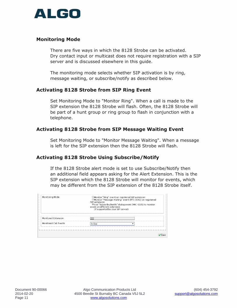
Activating 8128 Strobe Using Subscribe/Notify
If the 8128 Strobe alert mode is set to use Subscribe/Notify then
an additional field appears asking for the Alert Extension. This is the
SIP extension which the 8128 Strobe will monitor for events, which
may be different from the SIP extension of the 8128 Strobe itself.
Document 90-00066 Algo Communication Products Ltd (604) 454-3792 2014-02-20 4500 Beedie St Burnaby BC Canada V5J 5L2 [email protected] Page 12 www.algosolutions.com
Subscribe/notify per SIP RFC 4235 allows a SIP extension to request
status information for other SIP extensions.
The subscribe/notify information available from SIP servers varies by
vendor and release. As of FW Version 2.3 only ring and in-use are
enabled however it may also be possible to detect events such as
message waiting or ACD queue status. Please contact Algo for
current information.
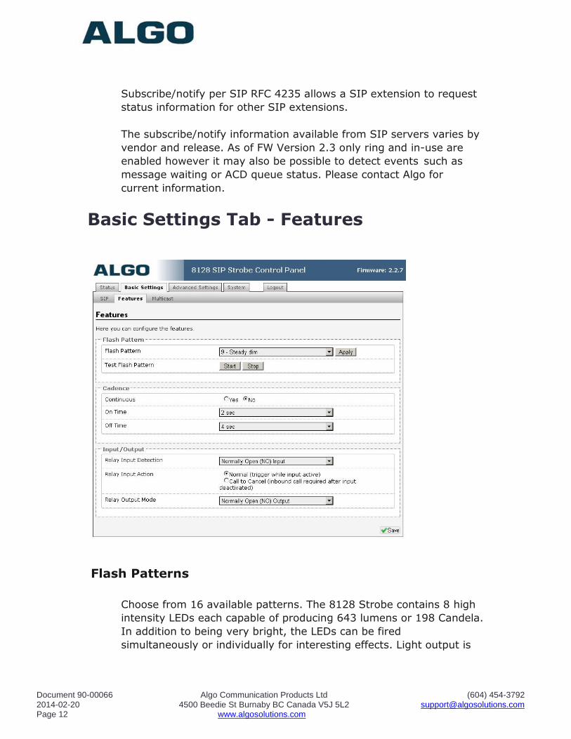
Basic Settings Tab - Features
Flash Patterns
Choose from 16 available patterns. The 8128 Strobe contains 8 high
intensity LEDs each capable of producing 643 lumens or 198 Candela.
In addition to being very bright, the LEDs can be fired
simultaneously or individually for interesting effects. Light output is
Document 90-00066 Algo Communication Products Ltd (604) 454-3792 2014-02-20 4500 Beedie St Burnaby BC Canada V5J 5L2 [email protected] Page 13 www.algosolutions.com
equally bright over 360 x 180 degrees and also illuminates the
mounting surface for even greater conspicuity.
Patterns 0 & 1 do not fire the center LEDs and are intended for a
ceiling mount application where light is required in every horizontal
direction but not straight down.
Pattern 11 does not fire the top and bottom LEDs and is intended for
a wall mount application in a hallway with maximum conspicuity to
the left, right, and center.
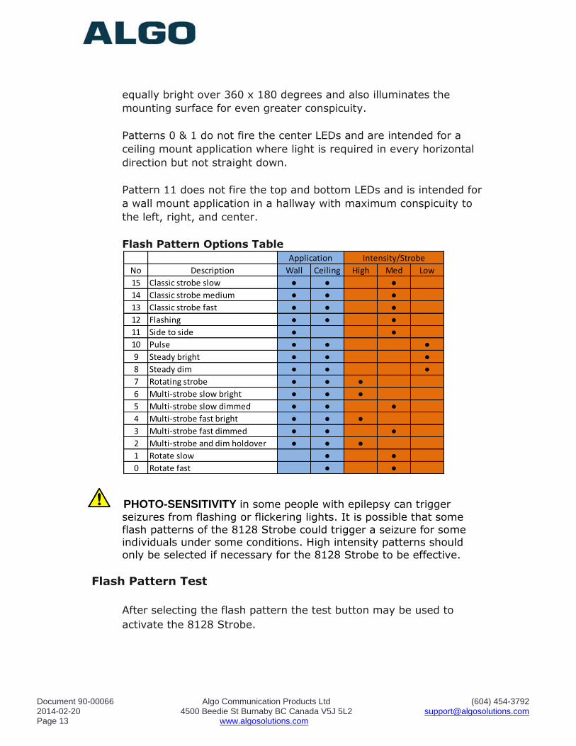
Flash Pattern Options Table
PHOTO-SENSITIVITY in some people with epilepsy can trigger
seizures from flashing or flickering lights. It is possible that some
flash patterns of the 8128 Strobe could trigger a seizure for some individuals under some conditions. High intensity patterns should
only be selected if necessary for the 8128 Strobe to be effective.
Flash Pattern Test
After selecting the flash pattern the test button may be used to
activate the 8128 Strobe.
No Description Wall Ceiling High Med Low
15 Classic strobe slow ● ● ●
14 Classic strobe medium ● ● ●
13 Classic strobe fast ● ● ●
12 Flashing ● ● ●
11 Side to side ● ●
10 Pulse ● ● ●
9 Steady bright ● ● ●
8 Steady dim ● ● ●
7 Rotating strobe ● ● ●
6 Multi-strobe slow bright ● ● ●
5 Multi-strobe slow dimmed ● ● ●
4 Multi-strobe fast bright ● ● ●
3 Multi-strobe fast dimmed ● ● ●
2 Multi-strobe and dim holdover ● ● ●
1 Rotate slow ● ●
0 Rotate fast ● ●
Application Intensity/Strobe
Document 90-00066 Algo Communication Products Ltd (604) 454-3792 2014-02-20 4500 Beedie St Burnaby BC Canada V5J 5L2 [email protected] Page 14 www.algosolutions.com
Cadence
The 8128 Strobe may be continuously active during an event, or
emulate a telephone ring on/off cadence. Using a cadence will also
ensure multiple 8128 Strobes using multicast remain synchronized.
Relay Input Detection Mode
The relay input feature can be set to be active when open or closed. This will depend on the triggering source. Generally, normally closed
circuits are preferred so that a wiring open fault will initiate activity.
Relay Input Action
The relay input may be used to flash the 8128 Strobe while the input is active, or latch the 8128 Strobe in an active state until cancelled by ringing the SIP ring extension.
For example, if the 8128 Strobe is connected to a door contact it can
be made to flash only while the door is open (input active). Or the door open event can trigger the 8128 Strobe which will remain active even after the door is closed. The 8128 Strobe in this mode (call to
cancel) must receive a SIP ring event to reset.
Relay Output Mode
When the 8128 Strobe is active this contact output will be either closed or open according to this selection.
Multicast Overview
The 8128 Strobe is able to send or receive IP multicast messages
over the network.
Without multicast, multiple 8128 Strobes would all require their own
SIP extensions and then be added to a hunt group or ring group for
simultaneous activation.
Multicasting offers an alternative that requires only one SIP extension and reduces network traffic. The first 8128 Strobe deployed can be configured as a multicast master, so that whatever flash pattern is
selected is also broadcast to the network using a multicast IP address. All of the other 8128 Strobes are configured as multicast
slaves and will activate in response to the multicast message.
Document 90-00066 Algo Communication Products Ltd (604) 454-3792 2014-02-20 4500 Beedie St Burnaby BC Canada V5J 5L2 [email protected] Page 15 www.algosolutions.com
The slave 8128 Strobes require a PoE network connection but do not
require registration to the SIP server.
In fact, since the 8128 Strobe can also be activated by dry contact closure, it is possible to have one or multiple 8128 Strobes activate in unison over multiple sites without any SIP server at all.
Multicast IP Addresses Each 8128 Strobe has its own IP address, and shares a common
multicast IP and port number (multicast zone) for multicast packets. The master unit transmits to a configurable multicast zone, and all
the slave units listen to the multicast zones assigned to them. When a master unit receives a valid SIP ring event, it will flash locally and also send out a special packet to the multicast zone. The network
switches and router see the packet and deliver it to all the members of the group. The multicast IP and port number must be the same on
all the master and slave units of one group. The user may define multiple zones by picking different multicast IP addresses and/or port numbers.
1. Multicast IP addresses range: 224.0.0.0/4
(from 224.0.0.0 to 239.255.255.255) 2. Port numbers range: 1 to 65535 3. By default, the 8128 Strobe is set to use the
multicast IP address 224.0.2.60 and the port numbers 50000-50008
Make sure that the multicast IP address and port number do not
conflict with other services and devices on the same network
Document 90-00066 Algo Communication Products Ltd (604) 454-3792 2014-02-20 4500 Beedie St Burnaby BC Canada V5J 5L2 [email protected] Page 16 www.algosolutions.com
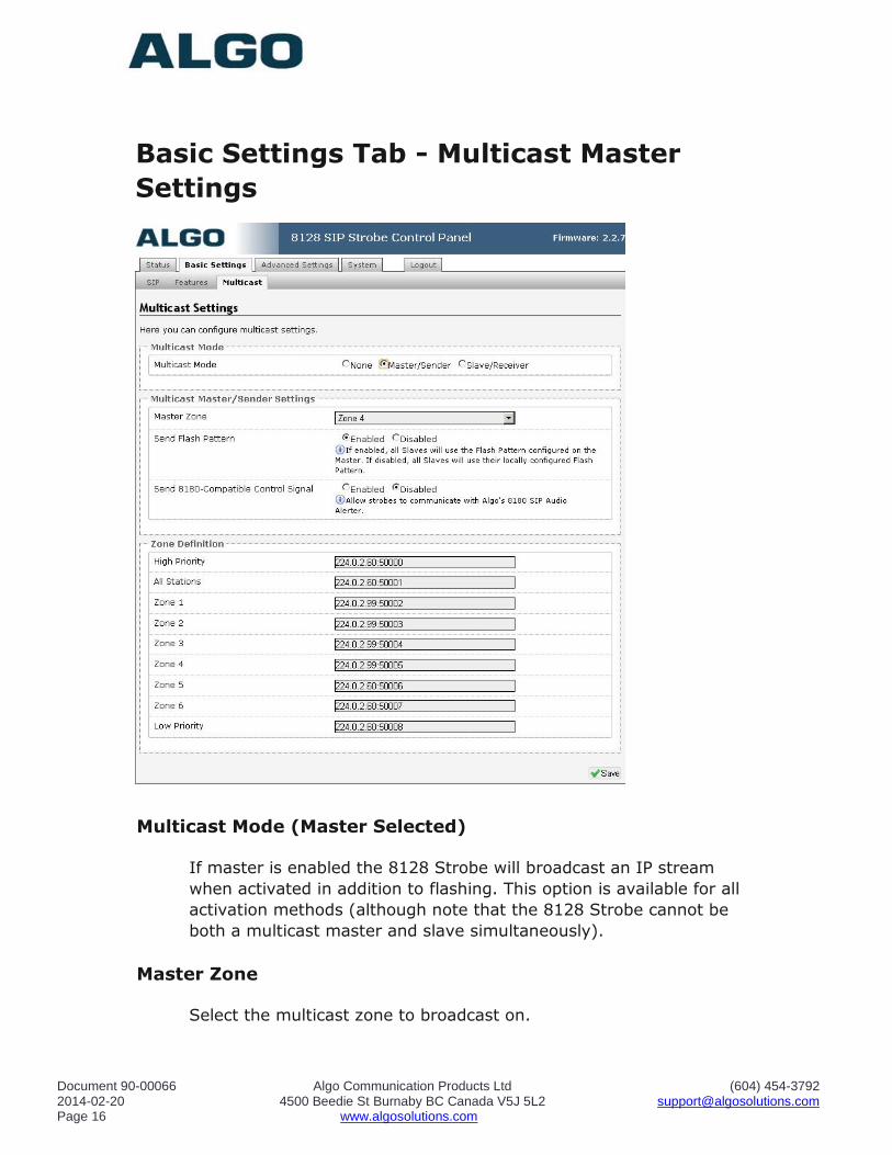
Basic Settings Tab - Multicast Master
Settings
Multicast Mode (Master Selected)
If master is enabled the 8128 Strobe will broadcast an IP stream
when activated in addition to flashing. This option is available for all
activation methods (although note that the 8128 Strobe cannot be
both a multicast master and slave simultaneously).
Master Zone
Select the multicast zone to broadcast on.
Document 90-00066 Algo Communication Products Ltd (604) 454-3792 2014-02-20 4500 Beedie St Burnaby BC Canada V5J 5L2 [email protected] Page 17 www.algosolutions.com
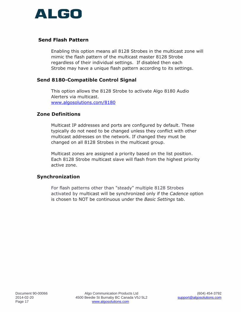
Send Flash Pattern
Enabling this option means all 8128 Strobes in the multicast zone will
mimic the flash pattern of the multicast master 8128 Strobe
regardless of their individual settings. If disabled then each
Strobe may have a unique flash pattern according to its settings.
Send 8180-Compatible Control Signal
This option allows the 8128 Strobe to activate Algo 8180 Audio
Alerters via multicast.
www.algosolutions.com/8180
Zone Definitions
Multicast IP addresses and ports are configured by default. These
typically do not need to be changed unless they conflict with other
multicast addresses on the network. If changed they must be
changed on all 8128 Strobes in the multicast group.
Multicast zones are assigned a priority based on the list position.
Each 8128 Strobe multicast slave will flash from the highest priority
active zone.
Synchronization
For flash patterns other than "steady" multiple 8128 Strobes
activated by multicast will be synchronized only if the Cadence option
is chosen to NOT be continuous under the Basic Settings tab.
Document 90-00066 Algo Communication Products Ltd (604) 454-3792 2014-02-20 4500 Beedie St Burnaby BC Canada V5J 5L2 [email protected] Page 18 www.algosolutions.com
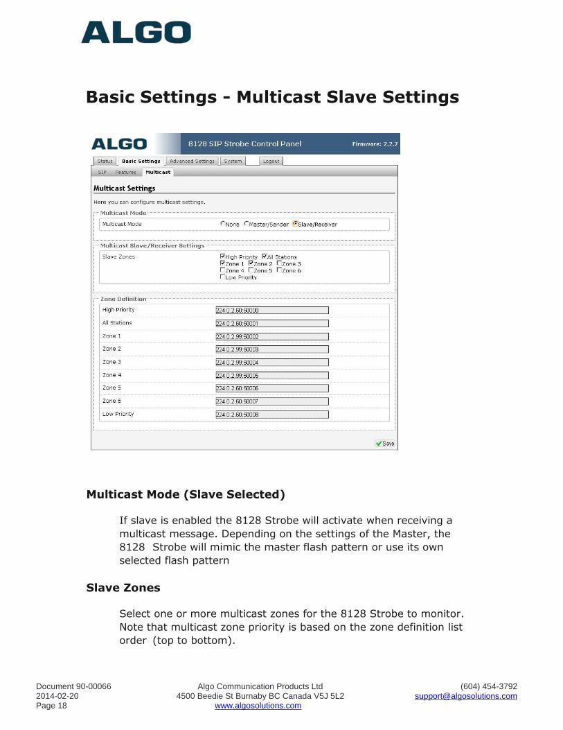
Basic Settings - Multicast Slave Settings
Multicast Mode (Slave Selected)
If slave is enabled the 8128 Strobe will activate when receiving a
multicast message. Depending on the settings of the Master, the
8128 Strobe will mimic the master flash pattern or use its own
selected flash pattern
Slave Zones
Select one or more multicast zones for the 8128 Strobe to monitor.
Note that multicast zone priority is based on the zone definition list
order (top to bottom).
Document 90-00066 Algo Communication Products Ltd (604) 454-3792 2014-02-20 4500 Beedie St Burnaby BC Canada V5J 5L2 [email protected] Page 19 www.algosolutions.com
Zone Definitions
See information in previous section under Master settings
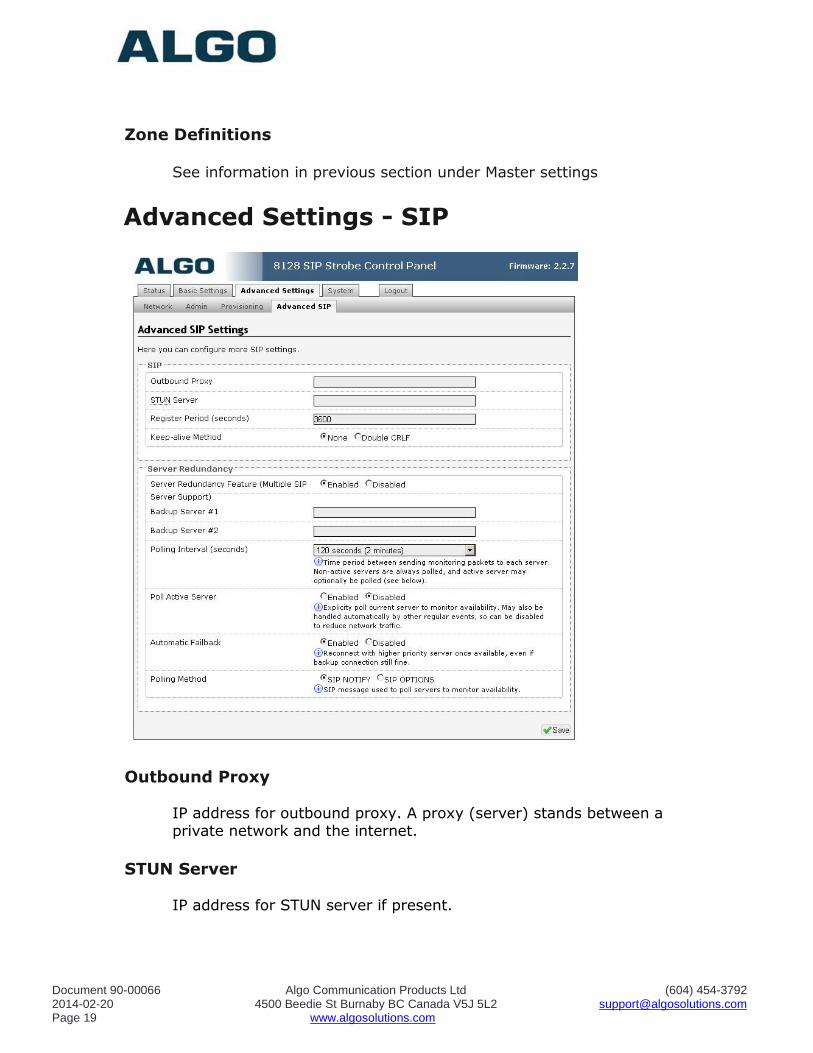
Advanced Settings - SIP
Outbound Proxy
IP address for outbound proxy. A proxy (server) stands between a private network and the internet.
STUN Server IP address for STUN server if present.
Document 90-00066 Algo Communication Products Ltd (604) 454-3792 2014-02-20 4500 Beedie St Burnaby BC Canada V5J 5L2 [email protected] Page 20 www.algosolutions.com
Register Period (seconds) Maximum requested period of time where the 8128 Strobe will re- register with the SIP server. Default setting is 3600 seconds (1 hour).
Only change if instructed otherwise.
Keep-alive Method
If Double CRLF is selected the 8128 Strobe will send a packet every 30 seconds (unless changed) to maintain connection with the SIP Server if behind NAT.
Server Redundancy Feature Two secondary SIP servers may be configured. The 8128 Strobe will
attempt to register with the primary server but switch to a secondary server when necessary. The configuration allows re-registration to
the primary server upon availability or to stay with a server until unresponsive.
Backup Server #1 If primary server is unreachable the 8128 Strobe will attempt to
register with the backup servers. If enabled the 8128 Strobe will always attempt to register with the highest priority server.
Backup Server #2
If backup server #1 is unreachable the 8128 Strobe will attempt to register with the 2nd backup server. If enabled the 8128 Strobe will
always attempt to register with the highest priority server.
Polling Intervals (seconds) Time period between sending monitoring packets to each server.
Non-active servers are always polled, and active server may optionally be polled (see below).
Poll Active Server Explicitly poll current server to monitor availability. May also be handled automatically by other regular events, so can be disabled to
reduce network traffic.
Document 90-00066 Algo Communication Products Ltd (604) 454-3792 2014-02-20 4500 Beedie St Burnaby BC Canada V5J 5L2 [email protected] Page 21 www.algosolutions.com
Automatic Failback Reconnect with higher priority server once available, even if backup connection still fine.
Polling Method
SIP message used to poll servers to monitor availability.
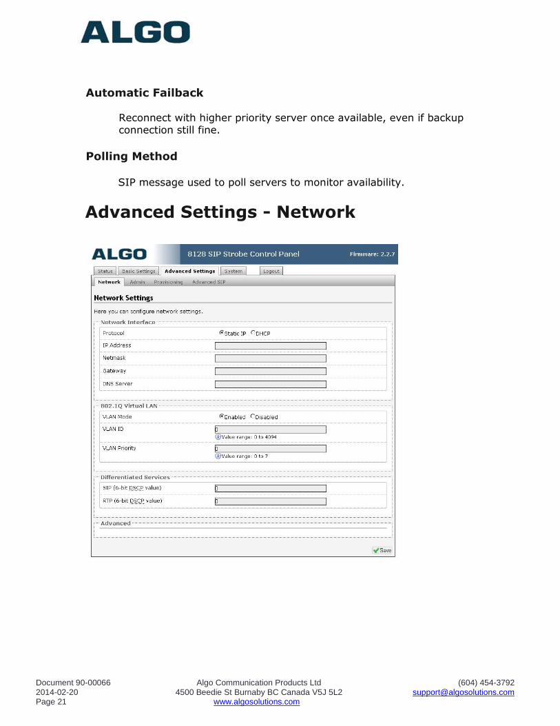
Advanced Settings - Network
Document 90-00066 Algo Communication Products Ltd (604) 454-3792 2014-02-20 4500 Beedie St Burnaby BC Canada V5J 5L2 [email protected] Page 22 www.algosolutions.com
Protocol
DHCP is an IP standard designed to make administration of IP
addresses simpler. When selected, DHCP will automatically configure
IP addresses for each 8128 Strobe on the network. Alternatively the
8128 Strobe can be set to a static IP address.
VLAN Mode
Enables or Disables VLAN Tagging. VLAN Tagging is the networking
standard that supports Virtual LANs (VLANs) on an Ethernet network.
The standard defines a system of VLAN tagging for Ethernet frames
and the accompanying procedures to be used by bridges and
switches in handling such frames. The standard also provides
provisions for a quality of service prioritization scheme commonly
known as IEEE 802.1p and defines the Generic Attribute Registration
Protocol.
VLAN ID
Specifies the VLAN to which the Ethernet frame belongs. A 12-bit
field specifying the VLAN to which the Ethernet frame belongs. The
hexadecimal values of 0x000 and 0xFFF are reserved. All other
values may be used as VLAN identifiers, allowing up to 4094 VLANs.
The reserved value 0x000 indicates that the frame does not belong to
any VLAN; in this case, the 802.1Q tag specifies only a priority and is
referred to as a priority tag. On bridges, VLAN 1 (the default VLAN
ID) is often reserved for a management VLAN; this is vendor specific.
VLAN Priority
Sets the frame priority level. Otherwise known as Priority Code Point
(PCP), VLAN Priority is a 3-bit field which refers to the IEEE 802.1p
priority. It indicates the frame priority level. Values are from 0
(lowest) to 7 (highest).
Differentiated Services (6-bit DSCP value)
Can provide quality of service if the DSCP protocol is supported on
your network. Can be specified independently for SIP control packets
versus RTP audio packets.
Document 90-00066 Algo Communication Products Ltd (604) 454-3792 2014-02-20 4500 Beedie St Burnaby BC Canada V5J 5L2 [email protected] Page 23 www.algosolutions.com
DHCP Timeout
Length of time (in seconds) following a request from the 8128 Strobe
to the DHCP server that the Strobe will wait before assuming the
server is not available. After such time, the 8128 Strobe will use its
default address of 192.168.1.111. Default time is 60 seconds.
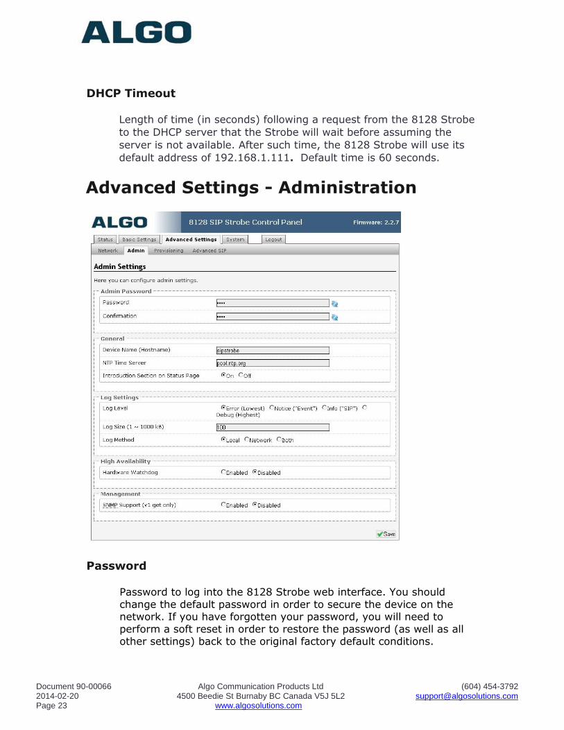
Advanced Settings - Administration
Password
Password to log into the 8128 Strobe web interface. You should
change the default password in order to secure the device on the network. If you have forgotten your password, you will need to
perform a soft reset in order to restore the password (as well as all other settings) back to the original factory default conditions.
Document 90-00066 Algo Communication Products Ltd (604) 454-3792 2014-02-20 4500 Beedie St Burnaby BC Canada V5J 5L2 [email protected] Page 24 www.algosolutions.com
Confirmation
Re-enter network admin password
Device Name Name to identify the device in the Algo Network Device Locator Tool.
NTP Time Server Allows the 8128 Strobe to synchronize to an external time server.
Introduction Section on Status Page Allows the introduction text to be hidden from the login screen.
Log Level Use on the advice of Algo technical support only.
Log Size Consult Algo technical support
Log Method Allows the 8128 Strobe to write to external Syslog server if the option for external (or both) is selected.
Log Server
If external (or both) is selected this is the address of the Syslog
server on the network.
Hardware Watchdog Use on the advice of Algo technical support only.
SNMP Support (v1 get only) Additional SNMP support is anticipated for future, but the 8128 Strobe will respond to a simple status query for automated
supervision. Contact Algo technical support for more information.
Document 90-00066 Algo Communication Products Ltd (604) 454-3792 2014-02-20 4500 Beedie St Burnaby BC Canada V5J 5L2 [email protected] Page 25 www.algosolutions.com
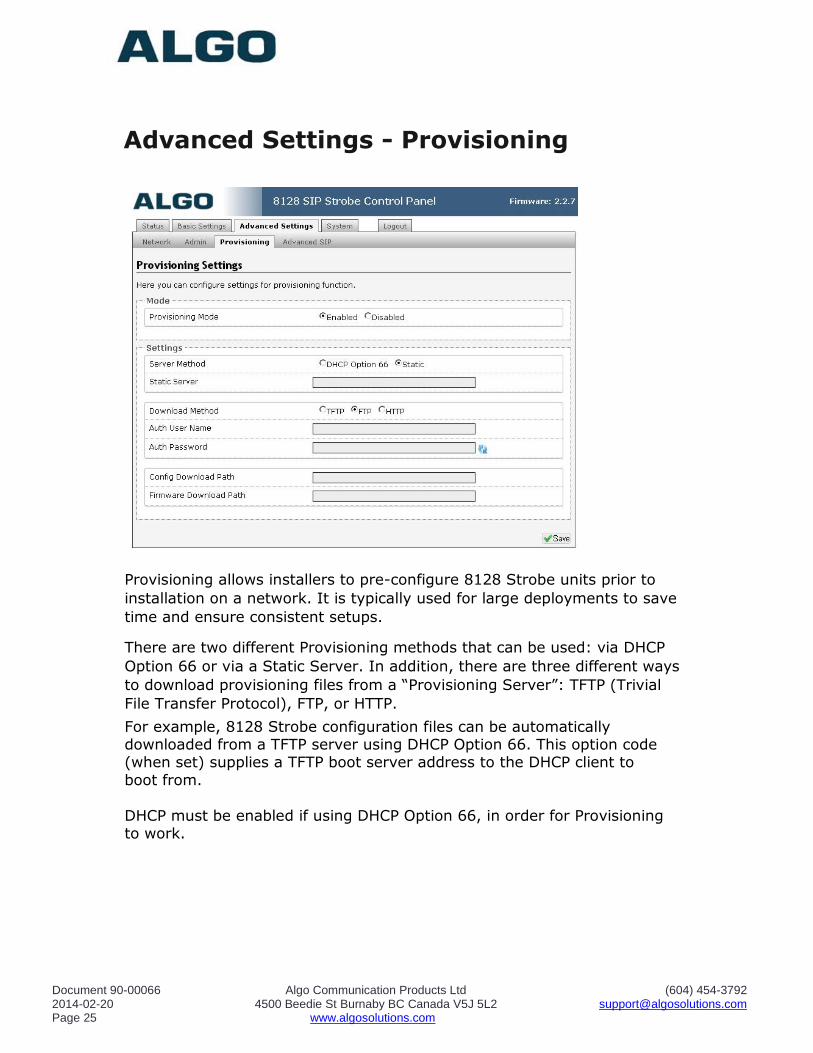
Advanced Settings - Provisioning
Provisioning allows installers to pre-configure 8128 Strobe units prior to
installation on a network. It is typically used for large deployments to save
time and ensure consistent setups.
There are two different Provisioning methods that can be used: via DHCP
Option 66 or via a Static Server. In addition, there are three different ways
to download provisioning files from a “Provisioning Server”: TFTP (Trivial
File Transfer Protocol), FTP, or HTTP.
For example, 8128 Strobe configuration files can be automatically downloaded from a TFTP server using DHCP Option 66. This option code (when set) supplies a TFTP boot server address to the DHCP client to
boot from.
DHCP must be enabled if using DHCP Option 66, in order for Provisioning to work.
Document 90-00066 Algo Communication Products Ltd (604) 454-3792 2014-02-20 4500 Beedie St Burnaby BC Canada V5J 5L2 [email protected] Page 26 www.algosolutions.com
One of two files can be uploaded on the Provisioning Server (for access via
TFTP, FTP, or HTTP):
1. generic file algop8128.conf, or 2. specific file algom[MAC].conf
MD5 Checksum
In addition to the .conf file, an .md5 checksum file must also be uploaded to the Provisioning server. This checksum file is used to verify that the .conf file is transferred correctly without error.
A tool such as can be found at the website address below may be used to
generate this file:
http://www.fourmilab.ch/md5
The application doesn’t need an installation. To use the tool, simply unzip and run the application (md5) from a command prompt. The proper .md5 file will be generated in the same directory.
If using the above tool, be sure to use the “-l” parameter to generate lower case letters.
Generating a generic configuration file
1. Connect an 8128 to the network
2. Access the 8128 Web Interface Control Panel
3. Configure the 8128 with desired options
4. Click on the System tab and then Maintenance.
5. Click “Backup” to download the current configuration file
6. Save the file settings.txt
7. Rename file settings.txt to algop8128.conf
8. File algop8128.conf can now be uploaded onto the Provisioning
server
If using a generic configuration file, extensions and credentials have to be entered manually once the 8128 Strobe has automatically downloaded the configuration file.
Document 90-00066 Algo Communication Products Ltd (604) 454-3792 2014-02-20 4500 Beedie St Burnaby BC Canada V5J 5L2 [email protected] Page 27 www.algosolutions.com
Generating a specific configuration file
1. Follow steps 1 to 6 as listed in the section “Generating a generic
configuration file”.
2. Rename file settings.txt to algom[MAC address].conf (e.g.
algom0022EE020009.conf)
3. File algom[MAC address].conf can now be uploaded on the
Provisioning server.
The specific configuration file will only be downloaded by the 8128 with the MAC address specified in the configuration file name. Since all the
necessary settings can be included in this file, the 8128 will be ready to work immediately after the configuration file is downloaded. The MAC address of each 8128 Strobe can be found on the back label of the unit.
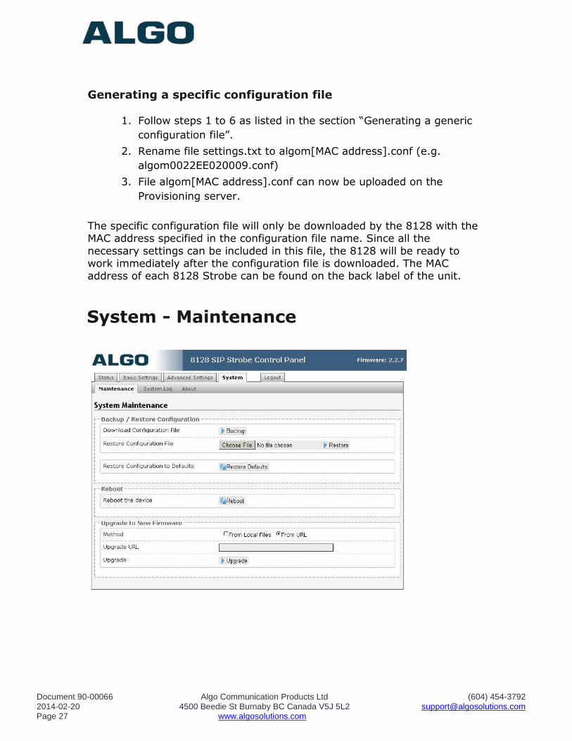
System - Maintenance
Document 90-00066 Algo Communication Products Ltd (604) 454-3792 2014-02-20 4500 Beedie St Burnaby BC Canada V5J 5L2 [email protected] Page 28 www.algosolutions.com
Download Configuration File
Save the device settings to a text file for backup or to setup a provisioning configuration file.
Restore Configuration File
Restore settings from a backup file.
Restore Configuration to Defaults
Resets all 8128 Strobe device settings to factory default values.
Reboot the Device
Reboots the device.
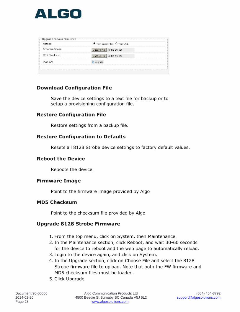
Firmware Image Point to the firmware image provided by Algo
MD5 Checksum Point to the checksum file provided by Algo
Upgrade 8128 Strobe Firmware
1. From the top menu, click on System, then Maintenance.
2. In the Maintenance section, click Reboot, and wait 30-60 seconds
for the device to reboot and the web page to automatically reload.
3. Login to the device again, and click on System.
4. In the Upgrade section, click on Choose File and select the 8128
Strobe firmware file to upload. Note that both the FW firmware and
MD5 checksum files must be loaded.
5. Click Upgrade
Document 90-00066 Algo Communication Products Ltd (604) 454-3792 2014-02-20 4500 Beedie St Burnaby BC Canada V5J 5L2 [email protected] Page 29 www.algosolutions.com
6. After the upgrade is complete, confirm that the firmware version
has changed (refer to top right of Control Panel).
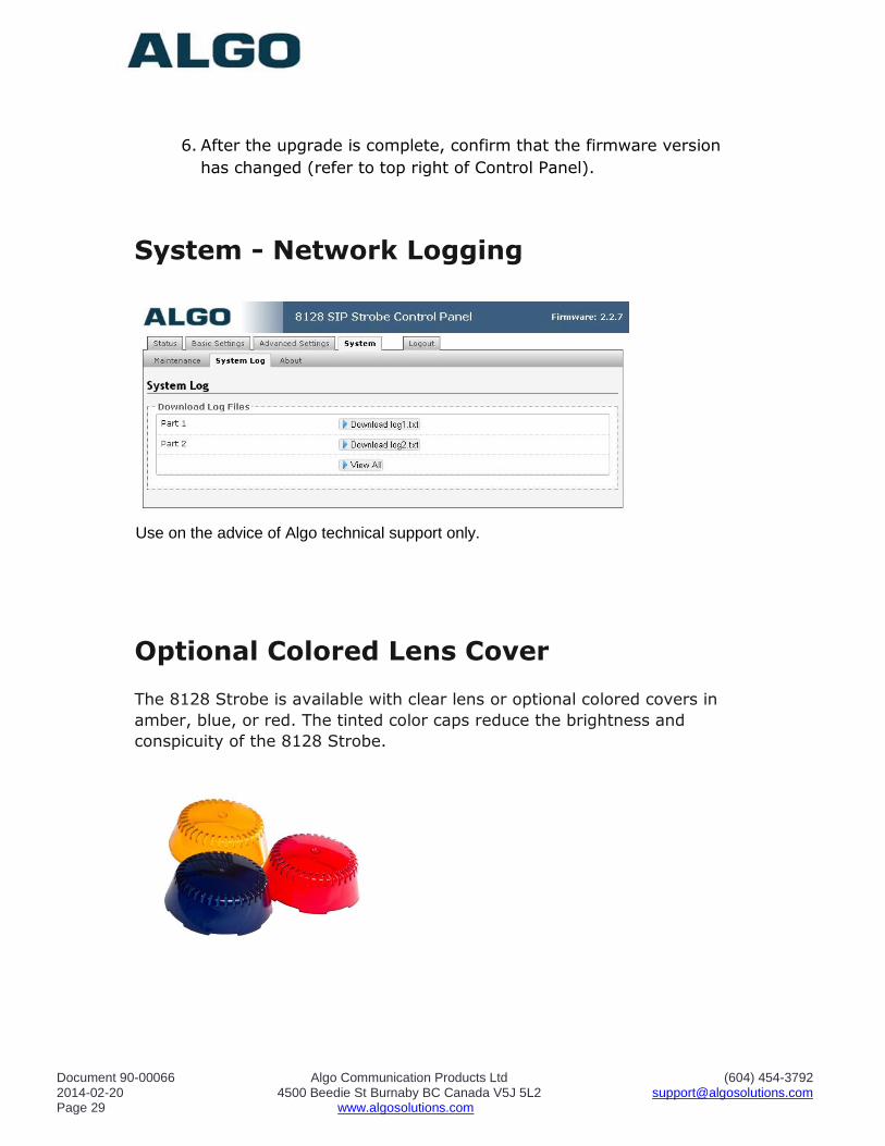
System - Network Logging
Use on the advice of Algo technical support only.
Optional Colored Lens Cover
The 8128 Strobe is available with clear lens or optional colored covers in
amber, blue, or red. The tinted color caps reduce the brightness and
conspicuity of the 8128 Strobe.
Document 90-00066 Algo Communication Products Ltd (604) 454-3792 2014-02-20 4500 Beedie St Burnaby BC Canada V5J 5L2 [email protected] Page 30 www.algosolutions.com
Specifications:
Power Input: 48 V PoE Class 0 (Max 12.95 W - Idle nominal 1 W)
Size: 4.8" W x 4.8" H x 3.0" D (12.2cm W x 12.2cm H x 7.6
cm D)
Optical: 8 LEDs 643 Lumens, 198 Cd
Strobe Triggers: SIP extension ring, Subscribe/Notify, multicast, dry contact input
Relay Output: Max 30 V 50 mA
Relay Input: Max 1 kOhm
Flash Patterns: 16 Selectable patterns
Programming: Web interface
Provisioning: TFTP, FTP, or HTTP.
NAT: STUN, CRLF Keep Alive
Environmental: -4 to +122 deg F (-20 to +50° C); 10-95% RH non-
condensing. Dry indoor location only unless wiring cavity protected from water ingress using supplied gaskets or
other protective measures. Compliance: EN60950:2001, IEEE 802.3-2008, RFC3261, RoHS, CE,
FCC, CSA/UL (USA & Canada)
Document 90-00066 Algo Communication Products Ltd (604) 454-3792 2014-02-20 4500 Beedie St Burnaby BC Canada V5J 5L2 [email protected] Page 31 www.algosolutions.com
FCC Compliance
This equipment has been tested and found to comply with the limits for a
Class A digital device, pursuant to part 15 of the FCC Rules. These limits are
designed to provide reasonable protection against interference in a
residential installation. This equipment generates, uses, and can radiate
radio frequency energy and, if not installed and used in accordance with the
instructions, may cause harmful interference to radio communications.
However, there is no guarantee that interference will not occur in a
particular installation. If this equipment does cause harmful interference to
radio or television reception, which can be determined by turning the
equipment off and on, the user is encouraged to try to correct the
interference by one or more of the following measures: 1) Reorient or
relocate the receiving antenna, 2) Increase the separation between the
equipment and receiver, 3) Connect the equipment into an outlet on a
circuit different from that to which the receiver is connected, or 4) Consult
the dealer or an experienced radio/TV technician for help.
Document 90-00066 Algo Communication Products Ltd (604) 454-3792 2014-02-20 4500 Beedie St Burnaby BC Canada V5J 5L2 [email protected] Page 32 www.algosolutions.com


![Manual write reference - bpums.ac.ir...H ˚7+ V’O 6" 6 7@ Z + !YFV5P 6" @ Z + !YFV5’ 2 2 &-" 9[3Q B ˝ V55-" 9 B\ V58-" 9 - V5= ˘ ˝ V5C 3 + ^6] V5G S B ˘ K ]6"Q > V5J ... #",](https://img.pdfslide.us/doc/110x75/60d598a8f3f78236117b9dbc/manual-write-reference-bpumsacir-h-7-vao-6-6-7-z-yfv5p-6.jpg)