Embed Size (px)
Citation preview
81-9059-0343-0 Rev D COUGAR AUDIO ROUTING SWITCHER
COUGAR AUDIO ROUTING SWITCHER
SERVICE AND ORDERING ASSISTANCE PESA Switching Systems, Inc.
330-A Wynn Drive Northwest Huntsville AL 35805-1961 USA
www.pesa.com
MAIN OFFICE Tel: 256.726.9200 Fax: 256.726.9271
SERVICE DEPARTMENT Tel: 256.726.9222 (24/7) Toll Free: 800.323.7372
Fax: 256.726.9268 Email: [email protected]
NATIONAL SALES OFFICE PESA Switching Systems, Inc. 35 Pinelawn Road, Suite 99-E
Melville NY 11747 USA Tel: 631.845.5020
Toll-free: 800.328.1008 Fax: 631.845.5023
Document Number 81-9059-0343 Revision D
PESA SWITCHING SYSTEMS i
81-9059-0343-0 Rev D COUGAR AUDIO ROUTING SWITCHER
© 2003 PESA Switching Systems, Inc. All Rights Reserved.
Cougar Audio is a trademark of PESA Switching Systems, Inc. in the United States and/or other countries.
Microsoft, Windows, and Windows NT are either registered trademarks or trademarks of Microsoft Corporation in the United States and/or other countries.
No part of this publication (including text, illustrations, tables, and charts) may be reproduced, stored in any retrieval system, or transmitted in any form or by any means, including but not limited to electronic, mechanical, photocopying, recording or otherwise, without the prior written permission of PESA Switching Systems, Inc.
All information, illustrations, and specifications contained in this publication are based on the latest product information available at the time of publication approval. The right is reserved to make changes at any time without notice.
Printed in the United States of America.
As of publication, this product had not completed FCC compliance testing.
April 2003
PESA SWITCHING SYSTEMS ii
81-9059-0343-0 Rev D COUGAR AUDIO ROUTING SWITCHER
About This Manual This manual provides detailed instructions for the installation, operation, and maintenance of the PESA Cougar Audio Routing Switcher.
Warnings, Cautions, and Notes
Warning statements identify conditions or practices that can result in personal injury or loss of life.
Caution statements identify conditions or practices that can result in damage to equipment.
Notes contain information important to the correct installation, operation, or maintenance of the equipment.
PESA SWITCHING SYSTEMS iii
81-9059-0343-0 Rev D COUGAR AUDIO ROUTING SWITCHER
Contents CHAPTER 1 – INTRODUCTION ..............................................................................................................3
1.1 Overview.........................................................................................................................................3 1.2 Specifications..................................................................................................................................4
CHAPTER 2 – OPERATION.....................................................................................................................6 2.1 General ...........................................................................................................................................6 2.2 Receipt Inspection ..........................................................................................................................6 2.3 Unpacking.......................................................................................................................................6 2.4 Location ..........................................................................................................................................7 2.5 Mounting .........................................................................................................................................7 2.6 Cabling............................................................................................................................................8 2.7 Level Code (Strobe) Selection.......................................................................................................9 2.8 Output/Input Code Selection ........................................................................................................10
2.8.1 Output Code ..........................................................................................................................10 2.8.2 Input Code.............................................................................................................................11
2.9 PS70V Setting Line Voltage .........................................................................................................12 2.10 PS70V Power Supply Installation .................................................................................................12 2.11 32X32 Audio Matrix Card Installation ...........................................................................................13 2.12 Rear Panel Connectors ................................................................................................................13
2.12.1 RCP Panel Connectors (J152-J155).....................................................................................13 2.12.2 Serial (CPU Link) Connectors (J145 and J146) ...................................................................14 2.12.3 Control (PRC) Connectors (J147 and J148) .........................................................................14 2.12.4 CPU Alarm Connector (J150)................................................................................................16 2.12.5 Matrix Card Alarm Connector (J158) ....................................................................................16 2.12.6 Power In/Out Connector (J135).............................................................................................17 2.12.7 Power Supply Alarm Connectors (J133 and J136) ...............................................................17 2.12.8 Reference (Sync) Connectors (1 and 2) ..............................................................................18 2.12.9 Audio Input and Output Connectors......................................................................................18
2.12.9.1 Input Signal Connectors (A INPUTS, B INPUTS).........................................................................19 2.12.9.2 Output Signal Connectors (A Outputs, B Outputs) .......................................................................20
2.13 System Connections.....................................................................................................................21 2.13.1 Connection Guide..................................................................................................................21
CHAPTER 3 – OPERATION...................................................................................................................22 3.1 Regulator Fault LED (Red) ...........................................................................................................22 3.2 CPU Fault LED (Red) ...................................................................................................................22 3.3 Power OK LED (Green)................................................................................................................22 3.4 32X32 Audio Matrix Card Adjustments ........................................................................................22
3.4.1 Voltage Adjustment ...............................................................................................................23 3.4.2 Common Mode Rejection Ratio (CMRR) ..............................................................................23 3.4.3 Gain .......................................................................................................................................24
CHAPTER 4 – MAINTENANCE .............................................................................................................25 4.1 32X32 Audio Matrix Card .............................................................................................................25
4.1.1 Control ...................................................................................................................................25 4.1.2 32X8 Control ICs ...................................................................................................................26 4.1.3 32X1 Crosspoint ....................................................................................................................26 4.1.4 Input.......................................................................................................................................26 4.1.5 Output....................................................................................................................................26 4.1.6 Power ....................................................................................................................................26
4.2 PS70V Power Supply ...................................................................................................................27 4.2.1 Circuit Description .................................................................................................................27
PESA SWITCHING SYSTEMS iv
81-9059-0343-0 Rev D COUGAR AUDIO ROUTING SWITCHER
List of Figures Figure 1. Cougar Audio Rear View...........................................................................................................3 Figure 2. Cougar Audio Front View ..........................................................................................................4 Figure 3. Chassis Installation....................................................................................................................7 Figure 4. Cables Attached to Supports.....................................................................................................8 Figure 5. Level Code (Strobe) Selection...................................................................................................9 Figure 6. Coding Switch Locations ...........................................................................................................9 Figure 7. Output Code Selection ............................................................................................................10 Figure 8. Input Code Selection ...............................................................................................................11 Figure 9. Cougar Audio Rear Panel........................................................................................................13 Figure 10. RCP Panel Connectors (J152-J155) .......................................................................................13 Figure 11. Serial (CPU Link) Connectors (J145 and J146) .....................................................................14 Figure 12. Control (PRC) Connectors (J147 and J148) ...........................................................................14 Figure 13. CPU Alarm Connector (J150)..................................................................................................16 Figure 14. Matrix Card Alarm Connector (J158).......................................................................................16 Figure 15. Power In/Out Connector (J135)...............................................................................................17 Figure 16. Power Supply Alarm Connectors (J133 and J136) .................................................................17 Figure 17. Reference (Sync) Connectors (1 and 2)..................................................................................18 Figure 18. Audio Input and Output Connectors ........................................................................................18 Figure 19. Input Signal Connector ............................................................................................................19 Figure 20. WECO Connector....................................................................................................................19 Figure 21. Input Signal Cable ...................................................................................................................19 Figure 22. Output Signal Connector .........................................................................................................20 Figure 23. WECO Connector....................................................................................................................20 Figure 24. Output Signal Cable ................................................................................................................20 Figure 25. Connection Guide....................................................................................................................21
List of Tables Table 1. Control Connector J147 Pinout ...............................................................................................15 Table 2. Control Connector J148 Pinout ...............................................................................................15
PESA SWITCHING SYSTEMS v
81-9059-0343-0 Rev D COUGAR AUDIO ROUTING SWITCHER
Chapter 1 – Introduction 1.1 Overview
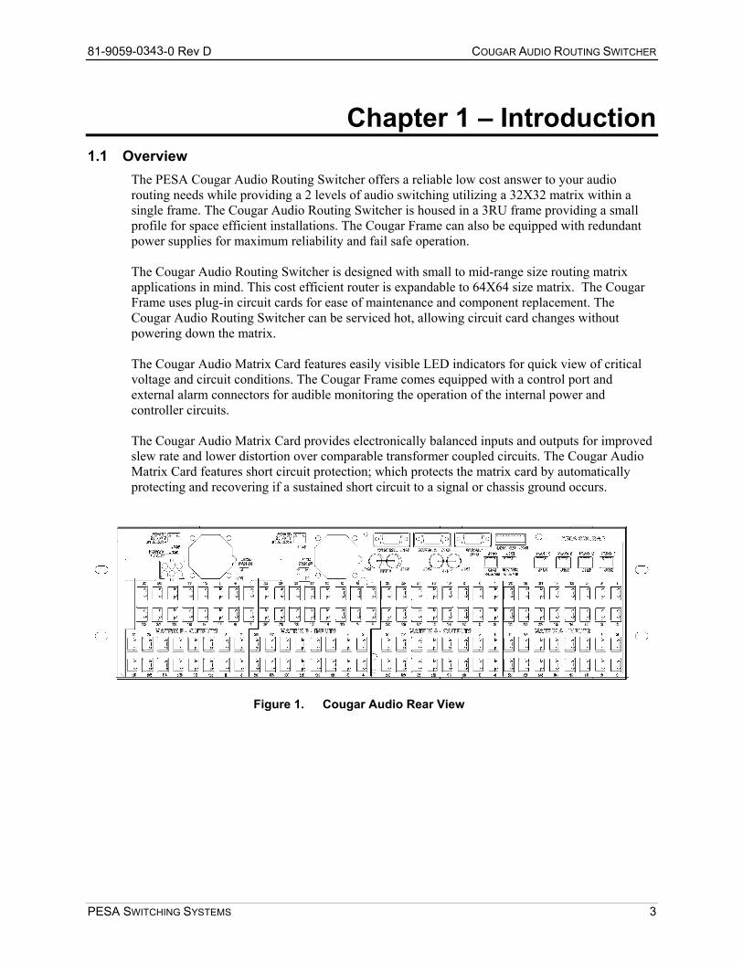
The PESA Cougar Audio Routing Switcher offers a reliable low cost answer to your audio routing needs while providing a 2 levels of audio switching utilizing a 32X32 matrix within a single frame. The Cougar Audio Routing Switcher is housed in a 3RU frame providing a small profile for space efficient installations. The Cougar Frame can also be equipped with redundant power supplies for maximum reliability and fail safe operation. The Cougar Audio Routing Switcher is designed with small to mid-range size routing matrix applications in mind. This cost efficient router is expandable to 64X64 size matrix. The Cougar Frame uses plug-in circuit cards for ease of maintenance and component replacement. The Cougar Audio Routing Switcher can be serviced hot, allowing circuit card changes without powering down the matrix. The Cougar Audio Matrix Card features easily visible LED indicators for quick view of critical voltage and circuit conditions. The Cougar Frame comes equipped with a control port and external alarm connectors for audible monitoring the operation of the internal power and controller circuits. The Cougar Audio Matrix Card provides electronically balanced inputs and outputs for improved slew rate and lower distortion over comparable transformer coupled circuits. The Cougar Audio Matrix Card features short circuit protection; which protects the matrix card by automatically protecting and recovering if a sustained short circuit to a signal or chassis ground occurs.
Figure 1. Cougar Audio Rear View
PESA SWITCHING SYSTEMS 3

81-9059-0343-0 Rev D COUGAR AUDIO ROUTING SWITCHER
Figure 2. Cougar Audio Front View
1.2 Specifications INPUT CHARACTERISTICS Level ........................................................................................................................... +28dBm Max Impedance .......................................................................................................................>60K Ohms Type .................................................................................................................Electrically Balanced Coupling.......................................................................................................................... Direct (DC) Common Mode Rejection Ratio .................................................................... -80dB (50Hz to 60Hz) Connector Type..................................................................................3-Pin, 2-Part, Detachable Plug OUTPUT CHARACTERISTICS Level ........................................................................................................... +28dBm into 600 Ohms Level Variation Between Inputs ............................................................................................ ±0.1dB Impedance ......................................................................................................................... <67 Ohms Type .................................................................................................................Electrically Balanced Number ....................................................................................................................................Single Coupling.......................................................................................................................... Direct (DC) DC on Outputs ....................................................................................................................... ±20mV Minimum Load @ 28dBm.................................................................................................600 Ohms Connector Type..................................................................................3-Pin, 2-Part, Detachable Plug GAIN CHARACTERISTICS Gain..................................................................................................................Adjustable to ±0.1dB Gain Stability ....................................................................................................................... ±0.05dB Adjustment Range............................................................................................ Approximately ±1dB FREQUENCY CHARACTERISTICS Sine Wave Response.................................................................................<±0.1dB, 20Hz to 20KHz -3dB to 200KHz Square Wave Response (Overshoot and Ringing).................................................<±5%, 3KHz 100µS Rise Time (20V P-P) DISTORTION CHARACTERISTICS Total Harmonic Distortion (THD) ............................................<0.10% @ 28dBm, 20Hz to 20KHz Intermodulation Distortion (IMD) ............................................<0.02% @ 28dBm, 20Hz to 20KHz
PESA SWITCHING SYSTEMS 4
81-9059-0343-0 Rev D COUGAR AUDIO ROUTING SWITCHER
CROSSTALK 20Hz to 20KHz ................................................................. <-92dB (All Inputs and Outputs Hostile) HUM AND NOISE (Unity Dynamic Range +28dBm) Wideband 10Hz to 300KHz............................................................................<-80dBm -108dBm 80KHz Low Pass Filter ...................................................................................<-88dBm -116dBm 30KHz Low Pass Filter ...................................................................................<-92dBm -120dBm 15KHz Low Pass Filter ...................................................................................<-94dBm -122dBm "A" Weighted..................................................................................................<-96dBm -124dBm SWITCHING CHARACTERISTICS DC Offset ..................................................................................................................... <10mV, Peak Switching Transients (30KHz Low Pass) .................................................................... <20mV, Peak
PESA SWITCHING SYSTEMS 5
81-9059-0343-0 Rev D COUGAR AUDIO ROUTING SWITCHER
Chapter 2 – Operation This section details the Cougar Audio Routing Switcher installation procedures. The following topics are discussed: • Receipt Inspection • Unpacking • Location • Mounting • Cabling • Level Code (Strobe) Selection • Input/Output Coding Selection • PS70V Setting Line Voltage • PS70V Power Supply Installation • 32X32 Audio Matrix Card Installation • Rear Panel Connectors • System Connections
2.1 General If specified when ordered, the Cougar Audio Routing Switcher will be configured for the intended system at the factory. Before attempting to install any frame, matrix card, controller card, or power supply; this section should be read carefully.
The Cougar Audio Routing Switcher contains static sensitive devices. Care should be used when it is necessary to handle the internal circuit cards. It is recommended that a ground wrist strap and grounding mat be used before attempting any equipment installations.
2.2 Receipt Inspection The Cougar Audio Routing Switcher was tested and inspected prior to leaving the factory. Upon receipt, inspect the equipment for shipping damage. If any damage is found, contact the carrier immediately and save all packing material.
2.3 Unpacking The Cougar Audio Matrix Switcher is comprised of a frame, backplane, a 32X32 Audio Matrix Card, and up to two PS70V Power Supplies. Prior to discarding packing material compare the parts received against the packing list. Carefully inspect the layers of packing material for any components which may have been overlooked during the initial unpacking.
PESA SWITCHING SYSTEMS 6
81-9059-0343-0 Rev D COUGAR AUDIO ROUTING SWITCHER
2.4 Location The Cougar Audio Routing Switcher may be located anywhere power is available. However, units should be mounted as close as possible to their associated equipment to minimize cable runs. Forced air cooling is provided by a small fans located at the back of the unit. Care should be taken not to block airflow around these fans. Installation should be in an area where the ambient temperature does not exceed 40°C (104°F) inside the equipment rack.
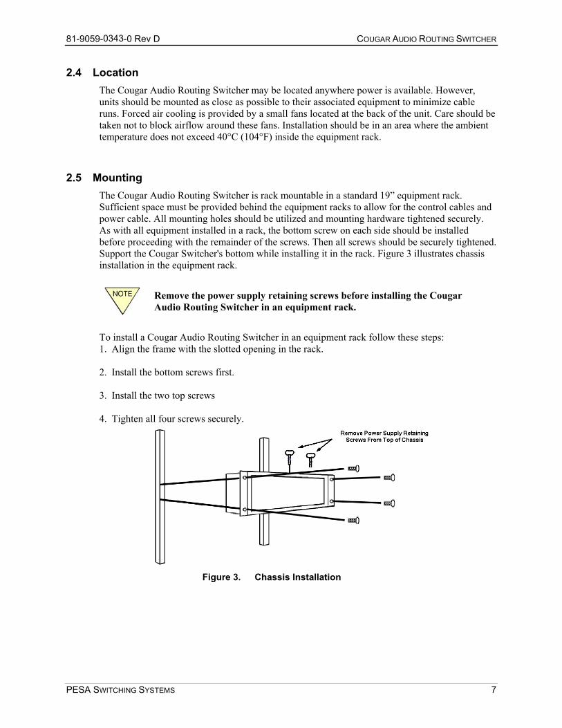
2.5 Mounting The Cougar Audio Routing Switcher is rack mountable in a standard 19” equipment rack. Sufficient space must be provided behind the equipment racks to allow for the control cables and power cable. All mounting holes should be utilized and mounting hardware tightened securely. As with all equipment installed in a rack, the bottom screw on each side should be installed before proceeding with the remainder of the screws. Then all screws should be securely tightened. Support the Cougar Switcher's bottom while installing it in the rack. Figure 3 illustrates chassis installation in the equipment rack.
Remove the power supply retaining screws before installing the Cougar Audio Routing Switcher in an equipment rack.
To install a Cougar Audio Routing Switcher in an equipment rack follow these steps: 1. Align the frame with the slotted opening in the rack. 2. Install the bottom screws first. 3. Install the two top screws 4. Tighten all four screws securely.
Figure 3. Chassis Installation
PESA SWITCHING SYSTEMS 7
81-9059-0343-0 Rev D COUGAR AUDIO ROUTING SWITCHER
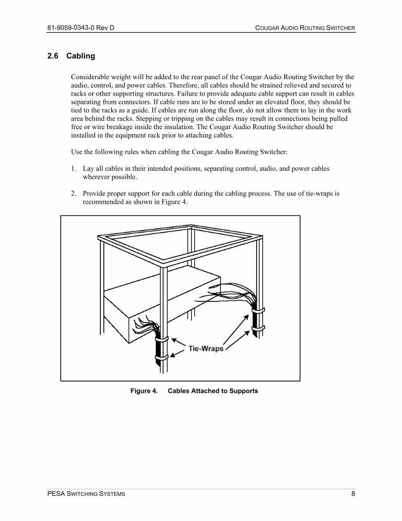
2.6 Cabling Considerable weight will be added to the rear panel of the Cougar Audio Routing Switcher by the audio, control, and power cables. Therefore, all cables should be strained relieved and secured to racks or other supporting structures. Failure to provide adequate cable support can result in cables separating from connectors. If cable runs are to be stored under an elevated floor, they should be tied to the racks as a guide. If cables are run along the floor, do not allow them to lay in the work area behind the racks. Stepping or tripping on the cables may result in connections being pulled free or wire breakage inside the insulation. The Cougar Audio Routing Switcher should be installed in the equipment rack prior to attaching cables. Use the following rules when cabling the Cougar Audio Routing Switcher: 1. Lay all cables in their intended positions, separating control, audio, and power cables
wherever possible. 2. Provide proper support for each cable during the cabling process. The use of tie-wraps is
recommended as shown in Figure 4.
Figure 4. Cables Attached to Supports
PESA SWITCHING SYSTEMS 8
81-9059-0343-0 Rev D COUGAR AUDIO ROUTING SWITCHER
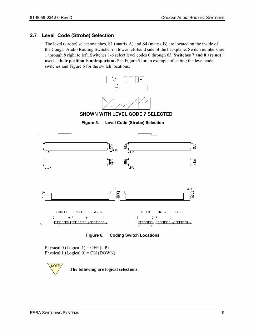
2.7 Level Code (Strobe) Selection The level (strobe) select switches, S1 (matrix A) and S4 (matrix B) are located on the inside of the Cougar Audio Routing Switcher on lower left-hand side of the backplane. Switch numbers are 1 through 8 right to left. Switches 1-6 select level codes 0 through 63. Switches 7 and 8 are not used – their position is unimportant. See Figure 5 for an example of setting the level code switches and Figure 6 for the switch locations.
Figure 5. Level Code (Strobe) Selection
Figure 6. Coding Switch Locations
Physical 0 (Logical 1) = OFF (UP) Physical 1 (Logical 0) = ON (DOWN)
The following are logical selections.
PESA SWITCHING SYSTEMS 9
81-9059-0343-0 Rev D COUGAR AUDIO ROUTING SWITCHER
SWITCH POSITIONS 6 5 4 3 2 1 STROBE LEVEL 0 0 0 0 0 0 0 STROBE LEVEL 1 0 0 0 0 0 1 STROBE LEVEL 2 0 0 0 0 1 0 STROBE LEVEL 3 0 0 0 0 1 1 STROBE LEVEL 4 0 0 0 1 0 0 STROBE LEVEL 5 0 0 0 1 0 1 STROBE LEVEL 6 0 0 0 1 1 0 STROBE LEVEL 7 0 0 0 1 1 1 UP TO.... STROBE LEVEL 62 1 1 1 1 1 0
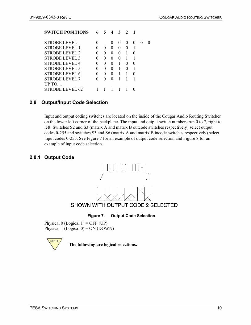
2.8 Output/Input Code Selection Input and output coding switches are located on the inside of the Cougar Audio Routing Switcher on the lower left corner of the backplane. The input and output switch numbers run 0 to 7, right to left. Switches S2 and S3 (matrix A and matrix B outcode switches respectively) select output codes 0-255 and switches S3 and S6 (matrix A and matrix B incode switches respectively) select input codes 0-255. See Figure 7 for an example of output code selection and Figure 8 for an example of input code selection.
2.8.1 Output Code
Figure 7. Output Code Selection
Physical 0 (Logical 1) = OFF (UP) Physical 1 (Logical 0) = ON (DOWN)
The following are logical selections.
PESA SWITCHING SYSTEMS 10
81-9059-0343-0 Rev D COUGAR AUDIO ROUTING SWITCHER
SWITCH POSITION 7 6 5 4 3 2 1 0 OUTPUTS OUTPUT CODE 0 0 0 0 0 0 0 0 0 0-32 OUTPUT CODE 1 0 0 0 0 0 0 0 1 33-64 OUTPUT CODE 2 0 0 0 0 0 0 1 0 65-96 OUTPUT CODE 3 0 0 0 0 0 0 1 1 97-128 OUTPUT CODE 4 0 0 0 0 0 1 0 0 129-160 OUTPUT CODE 5 0 0 0 0 0 1 0 1 161-192 OUTPUT CODE 6 0 0 0 0 0 1 1 0 193-224 OUTPUT CODE 7 0 0 0 0 0 1 1 1 225-256 UP TO.... OUTPUT CODE 255 1 1 1 1 1 1 1 1 8161-8192
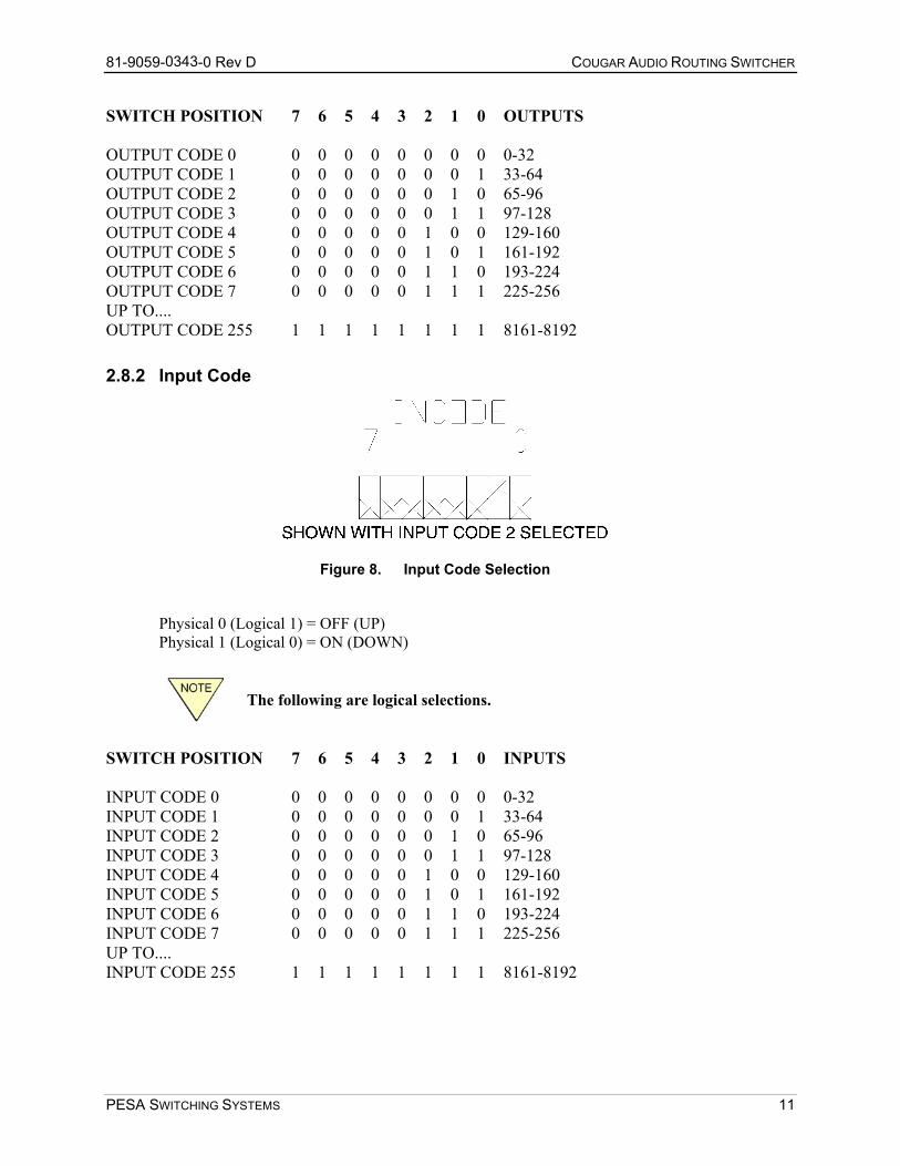
2.8.2 Input Code
Figure 8. Input Code Selection
Physical 0 (Logical 1) = OFF (UP) Physical 1 (Logical 0) = ON (DOWN)
The following are logical selections.
SWITCH POSITION 7 6 5 4 3 2 1 0 INPUTS INPUT CODE 0 0 0 0 0 0 0 0 0 0-32 INPUT CODE 1 0 0 0 0 0 0 0 1 33-64 INPUT CODE 2 0 0 0 0 0 0 1 0 65-96 INPUT CODE 3 0 0 0 0 0 0 1 1 97-128 INPUT CODE 4 0 0 0 0 0 1 0 0 129-160 INPUT CODE 5 0 0 0 0 0 1 0 1 161-192 INPUT CODE 6 0 0 0 0 0 1 1 0 193-224 INPUT CODE 7 0 0 0 0 0 1 1 1 225-256 UP TO.... INPUT CODE 255 1 1 1 1 1 1 1 1 8161-8192
PESA SWITCHING SYSTEMS 11
81-9059-0343-0 Rev D COUGAR AUDIO ROUTING SWITCHER
2.9 PS70V Setting Line Voltage The PS70V Power Supply has an AC Line Select Switch that allows you to select the required line voltage range. This switch is accessed by removing the plug-in power supply from the switcher, if the power supply is already installed. Be sure to disconnect the AC power cord before removing the power supply from the switcher. A separate jumper, located under the plastic safety cover surrounding the switch is used to add 15 volts to each switch setting. Using only the switch, nominal (± 10%) voltages available are 100, 120, 140, 200, 220, and 240. If the jumper is also moved, these voltages become 115, 135, 155, 215, 235, and 255.
Be sure the AC Line Select Switch and jumper are set to the correct positions before powering up the audio routing switcher.
Access is provided to the jumper by removing the two screws that secure the cover. These screws also secure the PC board to the mounting tray. Be sure to replace both screws. Tighten securely but avoid cracking the plastic cover.
2.10 PS70V Power Supply Installation The PS70V Power Supply(s) are installed in the upper right-hand portion of the Cougar Audio Routing Switcher. The Cougar Audio Routing Switcher is designed for the installation of up to two PS70V Power Supplies. If only one PS70V Power Supply is to be installed in the Cougar Audio Routing Switcher, install it in the left-hand position. To install the PS70V Power Supply or to install the PS70V Power Supplies in the Cougar Audio Routing Switcher take the following steps: 1. Align the primary power supply with the left-hand set of circuit card guides in the upper
right-hand side of the Cougar Audio Routing Switcher. 2. Carefully push the power supply into the switcher until the power supply connector makes
initial contact with backplane power connector. At this point, firmly but carefully continue pushing the power supply into the switcher while making sure the connectors are properly aligned. Continue pushing the power supply until it is in place and the connectors are firmly mated.
3. Align the secondary (redundant) power supply with the right-hand set of circuit card guides in the upper right-hand side of the Cougar Audio Routing Switcher.
4. Repeat step two. 5. If the Cougar Audio Routing Switcher is being shipped, install the two power supply retainer
screws through the top of the Cougar Audio Routing Switcher.
PESA SWITCHING SYSTEMS 12
81-9059-0343-0 Rev D COUGAR AUDIO ROUTING SWITCHER
2.11 32X32 Audio Matrix Card Installation The 32X32 Audio Matrix Card is installed in the lower portion of the Cougar Audio Routing Switcher. To install the matrix board in the Cougar Audio Routing Switcher take the following steps: 1. Align the matrix card shield plate with the set of circuit card guides in the lower portion of
the Cougar Audio Routing Switcher. 2. Carefully push the matrix board into the switcher until the circuit card connectors make initial
contact with backplane connectors. At this point, firmly but carefully continue pushing the matrix card into the switcher while making sure the connectors are properly aligned and that no connector pins are being bent. Continue pushing the card until it is in place and the connectors are firmly mated.
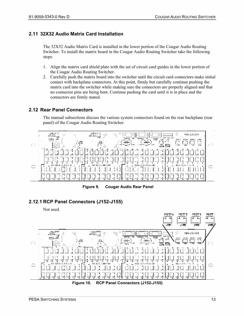
2.12 Rear Panel Connectors The manual subsections discuss the various system connectors found on the rear backplane (rear panel) of the Cougar Audio Routing Switcher.
Figure 9. Cougar Audio Rear Panel
2.12.1 RCP Panel Connectors (J152-J155) Not used.
Figure 10. RCP Panel Connectors (J152-J155)
PESA SWITCHING SYSTEMS 13
81-9059-0343-0 Rev D COUGAR AUDIO ROUTING SWITCHER
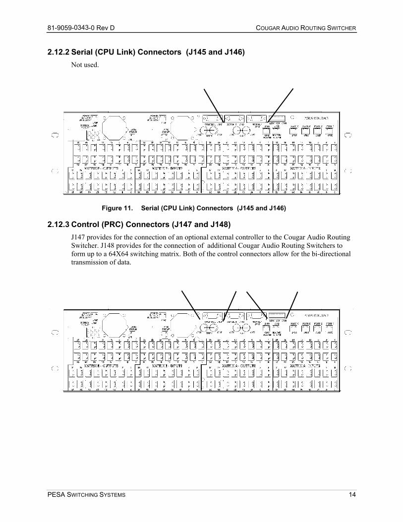
2.12.2 Serial (CPU Link) Connectors (J145 and J146) Not used.
Figure 11. Serial (CPU Link) C
2.12.3 Control (PRC) Connectors (J147 anJ147 provides for the connection of an optionSwitcher. J148 provides for the connection oform up to a 64X64 switching matrix. Both otransmission of data.
PESA SWITCHING SYSTEMS
onnectors (J145 and J146)
d J148) al external controller to the Cougar Audio Routing
f additional Cougar Audio Routing Switchers to f the control connectors allow for the bi-directional
14
81-9059-0343-0 Rev D COUGAR AUDIO ROUTING SWITCHER
The pinout of control connector J147 is as follows:
Table 1. Control Connector J147 Pinout
PIN NO. DESCRIPTION 1 GROUND 2 RX+ DATA 3 TX- DATA 4 GROUND 5 SPARE 6 GROUND 7 RX- DATA 8 TX+ DATA 9 GROUND
The pinout of control connector J148 is as follows:
Table 2. Control Connector J148 Pinout
PIN NO. DESCRIPTION 1 TX+ DATA 2 TX- DATA 3 GROUND 4 RX+ DATA 5 RX- DATA
For serial communications, the user should use a direct pin-for-pin cable for interfacing between the optional 3300 Controller and the peripheral equipment.
DO NOT use a "NULL MODEM" cable.
PESA SWITCHING SYSTEMS 15
81-9059-0343-0 Rev D COUGAR AUDIO ROUTING SWITCHER
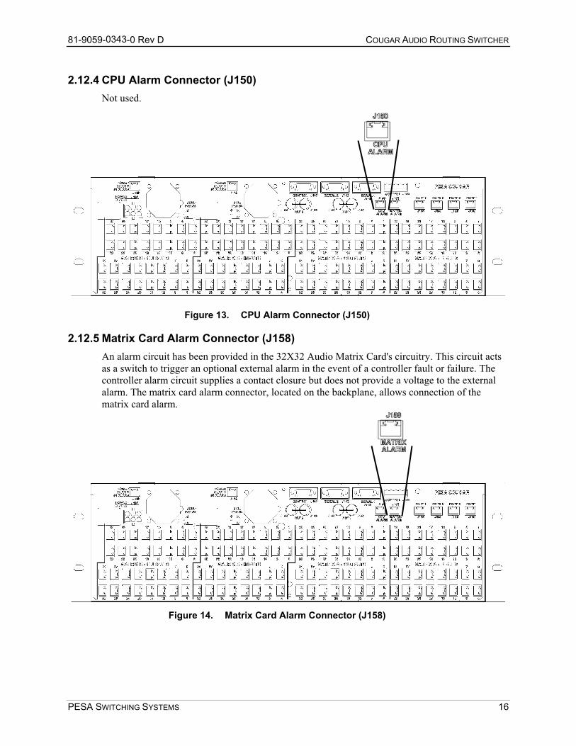
2.12.4 CPU Alarm Connector (J150) Not used.
Figure 13. CPU Alarm Connector (J15
2.12.5 Matrix Card Alarm Connector (J158) An alarm circuit has been provided in the 32X32 Audio Matrias a switch to trigger an optional external alarm in the event ocontroller alarm circuit supplies a contact closure but does noalarm. The matrix card alarm connector, located on the backpmatrix card alarm.
Figure 14. Matrix Card Alarm Connector
PESA SWITCHING SYSTEMS
0)
x Card's circuitry. This circuit acts f a controller fault or failure. The t provide a voltage to the external lane, allows connection of the
(J1
58)
16
81-9059-0343-0 Rev D COUGAR AUDIO ROUTING SWITCHER
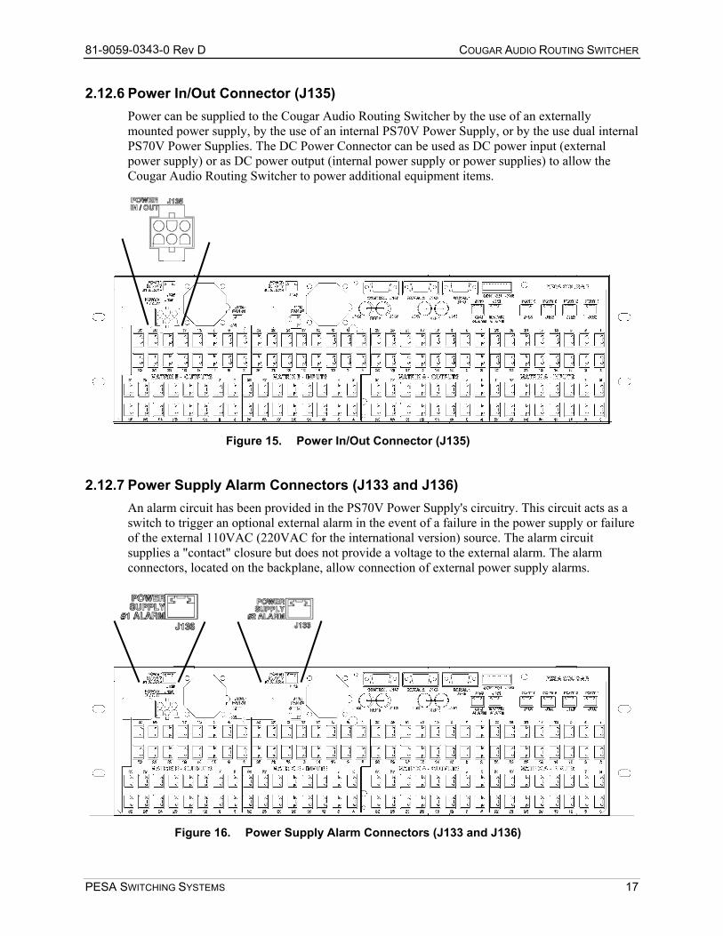
2.12.6 Power In/Out Connector (J135) Power can be supplied to the Cougar Audio Routing Switcher by the use of an externally mounted power supply, by the use of an internal PS70V Power Supply, or by the use dual internal PS70V Power Supplies. The DC Power Connector can be used as DC power input (external power supply) or as DC power output (internal power supply or power supplies) to allow the Cougar Audio Routing Switcher to power additional equipment items.
2.12.7
PESA S
Figure 15. Power In/Out Connector (J135)
Power Supply Alarm Connectors (J133 and J136) An alarm circuit has been provided in the PS70V Power Supply's circuitry. This circuit acts as a switch to trigger an optional external alarm in the event of a failure in the power supply or failure of the external 110VAC (220VAC for the international version) source. The alarm circuit supplies a "contact" closure but does not provide a voltage to the external alarm. The alarm connectors, located on the backplane, allow connection of external power supply alarms.
Figure 16.
WITCHING SYSTEMS
Power Supply Alarm Connectors (J133 and J136)
17
81-9059-0343-0 Rev D COUGAR AUDIO ROUTING SWITCHER
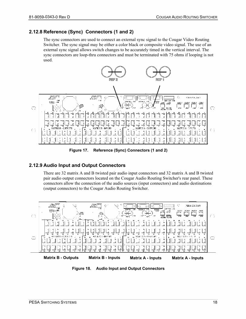
2.12.8 Reference (Sync) Connectors (1 and 2) The sync connectors are used to connect an external sync signal to the Cougar Video Routing Switcher. The sync signal may be either a color black or composite video signal. The use of an external sync signal allows switch changes to be accurately timed in the vertical interval. The sync connectors are loop-thru connectors and must be terminated with 75 ohms if looping is not used.
Figure 17. Re
2.12.9 Audio Input and OutputThere are 32 matrix A and B twpair audio output connectors loconnectors allow the connectio(output connectors) to the Cou
MatrMatrix B - Outputs
Figure 18. A
PESA SWITCHING SYSTEMS
ference (Sync) Connectors (1 and 2)
Connectors isted pair audio input connectors and 32 matrix A and B twisted
cated on the Cougar Audio Routing Switcher's rear panel. These n of the audio sources (input connectors) and audio destinations gar Audio Routing Switcher.
Matrix A - Inputs Matrix A - Inputs ix B - Inputs
udio Input and Output Connectors
18
81-9059-0343-0 Rev D COUGAR AUDIO ROUTING SWITCHER
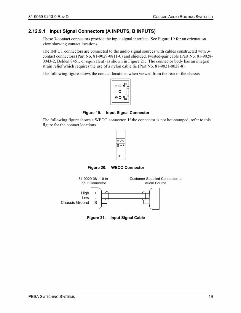
2.12.9.1 Input Signal Connectors (A INPUTS, B INPUTS) These 3-contact connectors provide the input signal interface. See Figure 19 for an orientation view showing contact locations.
The INPUT connectors are connected to the audio signal sources with cables constructed with 3-contact connectors (Part No. 81-9029-0811-0) and shielded, twisted-pair cable (Part No. 81-9028-0043-2, Belden 8451, or equivalent) as shown in Figure 21. The connector body has an integral strain relief which requires the use of a nylon cable tie (Part No. 81-9021-0028-8).
The following figure shows the contact locations when viewed from the rear of the chassis.
Figure 19. Input Signal Connector
The following figure shows a WECO connector. If the connector is not hot-stamped, refer to this figure for the contact locations.
Figure 20. WECO Connector
HighLow
Chassis Ground
+-S
81-9029-0811-0 toInput Connector
Customer Supplied Connector toAudio Source
Figure 21. Input Signal Cable
PESA SWITCHING SYSTEMS 19
81-9059-0343-0 Rev D COUGAR AUDIO ROUTING SWITCHER
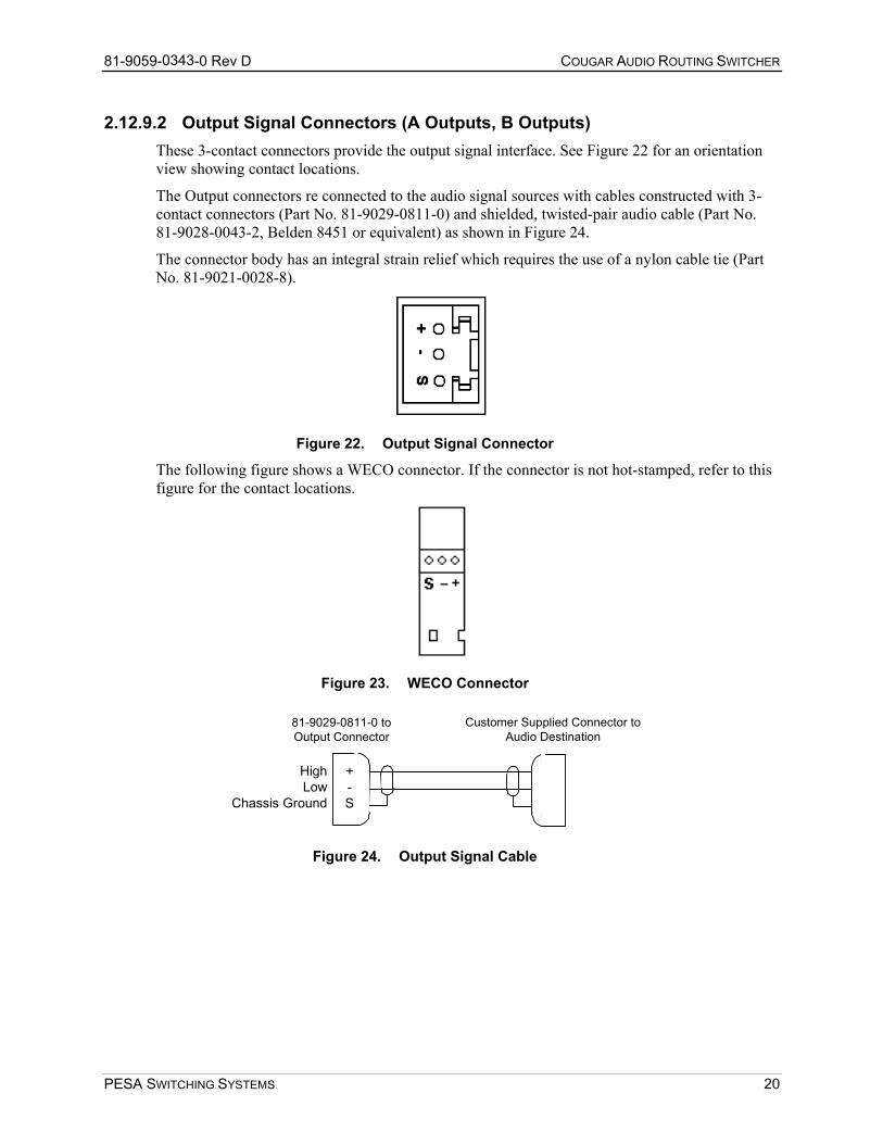
2.12.9.2 Output Signal Connectors (A Outputs, B Outputs) These 3-contact connectors provide the output signal interface. See Figure 22 for an orientation view showing contact locations.
The Output connectors re connected to the audio signal sources with cables constructed with 3-contact connectors (Part No. 81-9029-0811-0) and shielded, twisted-pair audio cable (Part No. 81-9028-0043-2, Belden 8451 or equivalent) as shown in Figure 24.
The connector body has an integral strain relief which requires the use of a nylon cable tie (Part No. 81-9021-0028-8).
Figure 22. Output Signal Connector
The following figure shows a WECO connector. If the connector is not hot-stamped, refer to this figure for the contact locations.
Figure 23. WECO Connector
HighLow
Chassis Ground
+-S
81-9029-0811-0 toOutput Connector
Customer Supplied Connector toAudio Destination
Figure 24. Output Signal Cable
PESA SWITCHING SYSTEMS 20
81-9059-0343-0 Rev D COUGAR AUDIO ROUTING SWITCHER
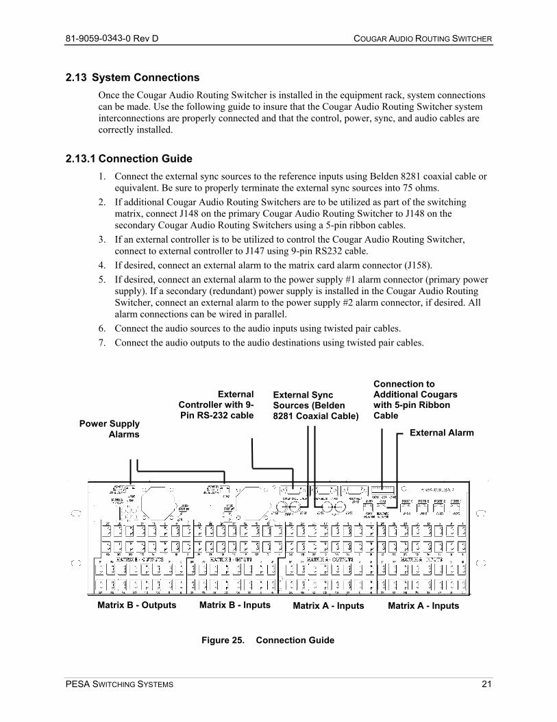
2.13 System Connections Once the Cougar Audio Routing Switcher is installed in the equipment rack, system connections can be made. Use the following guide to insure that the Cougar Audio Routing Switcher system interconnections are properly connected and that the control, power, sync, and audio cables are correctly installed.
2.13.1 Connection Guide 1. Connect the external sync sources to the reference inputs using Belden 8281 coaxial cable or
equivalent. Be sure to properly terminate the external sync sources into 75 ohms. 2. If additional Cougar Audio Routing Switchers are to be utilized as part of the switching
matrix, connect J148 on the primary Cougar Audio Routing Switcher to J148 on the secondary Cougar Audio Routing Switchers using a 5-pin ribbon cables.
3. If an external controller is to be utilized to control the Cougar Audio Routing Switcher, connect to external controller to J147 using 9-pin RS232 cable.
4. If desired, connect an external alarm to the matrix card alarm connector (J158). 5. If desired, connect an external alarm to the power supply #1 alarm connector (primary power
supply). If a secondary (redundant) power supply is installed in the Cougar Audio Routing Switcher, connect an external alarm to the power supply #2 alarm connector, if desired. All alarm connections can be wired in parallel.
6. Connect the audio sources to the audio inputs using twisted pair cables. 7. Connect the audio outputs to the audio destinations using twisted pair cables.
External Alarm
Connection to Additional Cougars with 5-pin Ribbon Cable
External Sync Sources (Belden 8281 Coaxial Cable)
ExternalController with 9-Pin RS-232 cable
Power SupplyAlarms
Matrix B - Inputs Matrix B - Outputs Matrix A - Inputs Matrix A - Inputs
Figure 25. Connection Guide
PESA SWITCHING SYSTEMS 21

81-9059-0343-0 Rev D COUGAR AUDIO ROUTING SWITCHER
Chapter 3 – Operation
The operation of the Cougar Audio Routing Switcher consists of periodically monitoring the 32X32 Audio Matrix Card LEDs. The matrix card LEDs and their proper indications are discussed in the following manual sections.
3.1 Regulator Fault LED (Red) The Regulator Fault LED (CR4) is utilized to visually indicate a regulator problem on the matrix card. A problem with the power supply or regulator circuits will cause this LED to light. However, in the event of a total power outage this LED will be rendered inoperable.
3.2 CPU Fault LED (Red) The CPU Fault LED (CR3) is utilized to visually indicate a microprocessor problem on the matrix card. A problem with the matrix card CPU or controller circuits will cause this LED to light.
3.3 Power OK LED (Green) The Power OK LED (CR2) on the front edge of the matrix card is utilized to visually indicate that the proper power supply voltage is being supplied to the card. A decrease in the brightness of this LED indicates an approximate 12% drop in voltage and should be checked. A 25% drop in voltage will cause the LED to extinguish.
3.4 32X32 Audio Matrix Card Adjustments The 32X32 Audio Matrix Card is adjusted at the PESA factory prior to shipment and should only have to be readjusted if equipment repairs are made or if the equipment configuration changes. The adjustment of the 32X32 Audio Matrix Card consists of adjusting the voltage adjustment, adjusting the common mode rejection ratio for each input, and adjusting the gain for each output. The following calibrated test equipment items or their equivalent is needed to accurately adjust the 32X32 Audio Matrix Card:
• Audio Generator • Distortion Analyzer • Digital Voltmeter • Oscilloscope • 600 Ohm Termination
PESA SWITCHING SYSTEMS 22
81-9059-0343-0 Rev D COUGAR AUDIO ROUTING SWITCHER
3.4.1 Voltage Adjustment The voltage adjustment provides the means to adjust the output of the 32X32 Audio Matrix Card's power regulator circuits. To adjust the voltage adjustment on the 32X32 Audio Matrix Card take the following steps: 1. Set the digital voltmeter to the 100V DC range. 2. Connect the digital voltmeter's high input to TP1 (+20V DC) and low input to TP3 (ground). 3. Set the voltage adjustment for a +20V DC ±0.5 reading on the digital voltmeter. 4. Disconnect the digital voltmeter's high input from TP1 and connect it to TP2 (-20V DC).
Check the digital voltmeter for -20V DC ±0.5 reading. 5. Disconnect the digital voltmeter from the test points.
3.4.2 Common Mode Rejection Ratio (CMRR) The input common mode rejection ratio adjustments provide the means to eliminate unwanted noise and hum on the 32X32 Audio Matrix Card's outputs. The CMRR adjustments are set at the PESA factory and should only need to be readjusted after port changes. To adjust the common mode rejection ratio adjustments on the 32X32 Audio Matrix Card take the following steps: 1. Short the high side (+ pin) of the selected audio input to the low side (- pin) of the same input
(i.e. short the plus and minus pins together). 2. Connect the audio generator to the distortion analyzer. 3. Adjust the audio generator for a 60Hz at +28dB output as displayed on the distortion
analyzer. 4. Disconnect the audio generator from the distortion analyzer. 5. Connect the high side of the audio generator's output to the short between the high side and
low side of the selected audio input. Connect the low side of the audio generator's output to ground.
6. Connect the distortion analyzer to the one of the audio outputs. 7. Switch the selected audio input to the selected audio output. 8. Adjust the CMRR for the selected audio input for a null (lowest) reading on the distortion
analyzer. The null reading should be at least -80dB below the input level.
9. Repeat steps 1-8 for each audio input. Once all of the CMRR adjustments have been completed, disconnect all test equipment.
PESA SWITCHING SYSTEMS 23
81-9059-0343-0 Rev D COUGAR AUDIO ROUTING SWITCHER
3.4.3 Gain The output gain adjustments provide the means to adjust the 32X32 Audio Matrix Card's outputs for unity gain (outputs equal to inputs). To adjust the gain adjustments on the 32X32 Audio Matrix Card take the following steps while referring to the matrix card's component: 1. Connect the audio generator to the distortion analyzer. 2. Adjust the high frequency generator for a 10KHz at +28dB display on the distortion analyzer. 3. Disconnect the audio generator from the distortion analyzer. 4. Connect the audio generator to one of the audio matrix card's inputs. 5. Connect the distortion analyzer to one of the audio matrix card's outputs. 6. Switch the selected input to the selected output. 7. Adjust the gain adjustment correlating to the selected output for a +28dB ±0.1dB display on
the distortion analyzer. 8. Repeat steps 5-7 until all of the audio matrix card's gain adjustments have been completed.
Once all of the gain adjustments have been completed, disconnect all test equipment. The gain will change a little less than 1dB when a 600 ohm termination is used on an output. The gain adjustment is intended (only) to make up for the 1dB change. PESA recommends leaving the outputs unterminated. The Cougar Audio Routing Switcher is shipped with its outputs set for unity gain with no termination.
PESA SWITCHING SYSTEMS 24
81-9059-0343-0 Rev D COUGAR AUDIO ROUTING SWITCHER
Chapter 4 – Maintenance
The Cougar Audio Routing Switcher provides 2 levels of switching within a 32X32 audio matrix. The 32 matrix A and B audio inputs and outputs are electronically balanced for improved slew rate and lower distortion levels.
4.1 32X32 Audio Matrix Card The 32X32 Audio Matrix Card contains a 32X32 matrix consisting of several main circuits. This discussion will be broken down to the main circuits.
4.1.1 Control The microprocessor controller (U316) is used to interface switch commands from the PRCI control port (U256) to the switch matrix and return status information to the controller. Communications to and from the system controller are through U246, a RS485 receiver and transmitter. System timing is provided to the microprocessor by U1411, a 7.3728MHz oscillator. The microprocessor divides the timing single from the oscillator by a factor of four to form the system clock single. Reset for the microprocessor is provided by U317. U326, a power supply monitor, monitors the output of the 32X32 Audio Matrix Card's power circuits and reports power fault conditions to the microprocessor. CR3 is utilized by power supply monitor circuit to provide a visual indication of power supply fault conditions. Matrix output, input, and level coding is read from the backplane through U290, U305, and U306 respectively for matrix A and U293, U292, and U291 respectively for matrix B. U277, U295, U276, and U307 provide address decoding for the 32X32 Audio Matrix Card. U278 and U279 comprise the nonvolatile RAM for the processor. C156 provides memory backup voltage for approximately seven days as long as the matrix card is not removed from the Cougar Frame. CR3 is utilized by the processor on the 32X32 Audio Matrix Card to indicate a CPU fault condition. An external alarm connection is provided by U327. The external connection can be utilized to audibly indicate CPU fault conditions. Two external sync signals are used for timing switches as set by SW1. The external sync can be color black or composite sync. U185 and U206 decode the composite signal to an even/odd field signal which is used by the microprocessor.
PESA SWITCHING SYSTEMS 25
81-9059-0343-0 Rev D COUGAR AUDIO ROUTING SWITCHER
4.1.2 32X8 Control ICs The 32X8 control ICs (U198, U225, U199, and U226) are responsible for the control and switching of 32 inputs to 8 outputs for matrix A. The 32X8 control ICs (U204, U227, U205, and U228) are responsible for the control and switching of 32 inputs to 8 outputs for matrix B. The control of the control ICs is accomplished by signals sent over the control bus by the microprocessor. The control ICs interpret the signals and provide control signals and the BUSEN to the 32X1 crosspoint switch circuits. U215 and U216 provide the reset, data, and clock signals for the 32X8 control ICs.
4.1.3 32X1 Crosspoint The 32X1 crosspoint switches are responsible for switching one of 32 inputs to an output. The 32X1 crosspoint switches are comprised of two 16X1 crosspoints which form a 32X1 matrix. The switching of a selected input signal to a selected output by 32X1 crosspoint is controlled by the state of the associated BUS and BUSEN data lines. The 32X1 crosspoint switches are also responsible for providing the selected output to the associated output circuit on the 32X32 Audio Matrix Card.
4.1.4 Input The input circuits on the 32X32 Audio Matrix Card provide the initial conditioning and termination of the audio input signals. The input circuits are comprised of an operational amplifier and its associated components. Common mode rejection ratio adjustments in each input circuit provide the means to eliminate unwanted hum and noise on the input audio signals. The input circuits also provide the connection of the audio input signals to the 32X1 crosspoint switch circuits.
4.1.5 Output The output circuits on the 32X32 Audio Matrix Card are responsible for providing an electronically balanced output and driving the output lines. The output circuits are comprised of two dual staged operational amplifiers and their associated components. The first stage of primary operational amplifier is responsible for conditioning the audio output signal and the second stage of the primary operational amplifier is responsible for inverting the audio output to provide an electronically balanced output. The secondary operational amplifier is responsible for driving the audio output lines. The audio output lines are driven through precision 33.2 ohm resistors. An adjustment is provided in each output circuit to adjust the output for unity gain.
4.1.6 Power The power regulator circuits on the 32X32 Audio Matrix Card are responsible for producing all of the regulated operational voltages required by the matrix card's electronic circuits. The heart of the power supply circuit on the video matrix card is a switching regulator (U300) which produces the +20V DC and -20V DC. Adjustment of the output of the switching regulator is provided by R492, a variable resistor. Regulation of the +5V DC supply is provided by U281. CR2 provides a visual indication that power is being applied to the input of the regulator circuits. Fuses F1 and F2 protect the power regulator circuits from overload conditions and protect the audio matrix card from overload damage. The power circuits also contain a fan speed regulator circuit which works in conjunction with fan regulator in the PS70V Power Supply to control the speed of the associated chassis fans. As the temperature of the matrix card's circuits increase the fan speed will
PESA SWITCHING SYSTEMS 26
81-9059-0343-0 Rev D COUGAR AUDIO ROUTING SWITCHER
increase. Inversely as the matrix card's circuits decrease in temperature the fan speed will slow down dependent upon the temperature of the associated PS70V Power Supply's circuits.
4.2 PS70V Power Supply The PS70V Power Supply is an unregulated power source that supplies positive and negative voltages to the Cougar Audio Routing Switcher. The PS70V has an AC Select Switch that allows you to select the required voltage range. This switch is accessed by removing the plug-in supply. Insure that power is off before changing the switch setting. A separate jumper, located under the plastic safety cover surrounding the switch is used to add 15 volts to each switch setting. Using only the switch, nominal (± 10%) voltages available are 100, 120, 140, 200, 220, and 240. If the jumper is also moved, these voltages become 115, 135,155, 215, 235, and 255. Access is provided to the jumper by removing the two screws that secure the cover. These screws also secure the PC card to the mounting tray. Be sure to replace both screws. Tighten securely but avoid cracking the plastic cover.
4.2.1 Circuit Description Input fuses provide overcurrent protection from internal faults and output overloads. If a fuse opens, correct the overcurrent condition then replace the fuse(s). Both sides of the line are fused. The AC selector switch interconnects the transformer primaries in series and/or parallel combinations to provide the proper ratio for the input line voltage. The secondaries drive full wave rectifiers with capacitor input filters providing positive and negative voltages with respect to ground. After the filters, series diodes are used to allow supplies to be paralleled for redundancy. The diodes assure that one supply cannot load the output of the others in case of a shorted diode or capacitor. A temperature sensing circuit controls the fan speed according to the air temperature and the temperature of the rectifier diodes. The fan usually runs at half speed at normal temperature (25°C). A circuit senses the voltages across the filter capacitors. If the combined voltages decrease by approximately 25% from normal, the green LED is turned off. The red LED, located on the PC card, is then lit and the alarm "closure" is activated. The green LED, located on the front panel, serves as a rough indicator of output voltage; it dims as the combined positive and negative voltages decrease. These supplies are unregulated and follow input line changes and output load variations.
PESA SWITCHING SYSTEMS 27