Embed Size (px)
Citation preview

3,350+OPEN ACCESS BOOKS
108,000+INTERNATIONAL
AUTHORS AND EDITORS115+ MILLION
DOWNLOADS
BOOKSDELIVERED TO
151 COUNTRIES
AUTHORS AMONG
TOP 1%MOST CITED SCIENTIST
12.2%AUTHORS AND EDITORS
FROM TOP 500 UNIVERSITIES
Selection of our books indexed in theBook Citation Index in Web of Science™
Core Collection (BKCI)
Chapter from the book The Delivery of NanoparticlesDownloaded from: http://www.intechopen.com/books/the-delivery-of-nanoparticles
PUBLISHED BY
World's largest Science,Technology & Medicine
Open Access book publisher
Interested in publishing with IntechOpen?Contact us at [email protected]
19
Platinum Fuel Cell Nanoparticle Syntheses: Effect on Morphology, Structure
and Electrocatalytic Behavior
C. Coutanceau, S. Baranton and T.W. Napporn e-Lyse, Laboratoire de Catalyse en Chimie Organique, UMR CNRS-Université de Poitiers,
France
1. Introduction
Because of high cost and low availability of platinum, which yet remains unavoidable as catalyst in proton exchange membrane fuel cells for achieving acceptable electric performances, numerous synthesis methods of Pt nanoparticles were developed. The decrease of the particle size in a certain extent leads to a decrease of the noble metal content in the fuel cell electrodes and also to an increase of their real surface area. Physical methods such as plasma sputtering of metals [Brault et al., 2004; Caillard et al., 2007, Cho et al., 2008], laser ablation [Perrière et al., 2001; Boulmer et al., 2006], metal organic chemical vapor deposition [Billy et al., 2010], etc., have been and are still developed for preparing low loaded platinum based electrodes for Proton Exchange Membrane Fuel Cell (PEMFC). Although such methods present important interests due to the high control of metal deposition parameters, they involve also important material losses in the deposition chamber and on the electrode mask. Metal electrodeposition can also be classified as a physical method of electrode preparation [Chen et al., 2003; Ayyadurai et al., 2007]. This method consists in the electrochemical reduction of a metallic salt on an electron conductive support. It is then possible by varying the current or potential sequence applied to the electrode to control or at least to change the structure of the catalyst. However, the faradic yield is often very low because hydrogen evolution can occur as soon as platinum is deposited on the substrate [Coutanceau et al., 2004].
Chemical methods for platinum nanoparticle synthesis allow obtaining platinum nanoparticles deposited and well disseminated on a carbon powder in a simplest and more versatile manner. Amongst the chemical methods for nanostructured catalyst preparation, the impregnation-reduction method is often used in the field of heterogeneous catalysis. The principle of such method consists in the reduction of metallic salts impregnating a carbon powder with either a reducing gas or by thermal treatment under inert atmosphere [Vigier et al., 2004; Coutanceau et al., 2008]. Different possibilities exist. For example, the cationic exchange method [Richard & Gallezot, 1987] consists in activating a carbon support with sodium hypochlorite to form surface carboxylic acid groups, which are transformed into ammonium salts after treatment with ammonia. The ammonium groups are exchanged by contact with a Pt(NH3)4OH2 alkaline complex, and the catalyst precursor is reduced at 300°C
www.intechopen.com
The Delivery of Nanoparticles
404
under pure hydrogen flow to form metallic particles. Pt/C catalyst prepared by this method Were well disseminated on the support, and displayed a mean particle size close to 2 nm. But, the total loading of metal was very limited and did not exceed 10 wt%, which is a too low value for PEMFC application. Higher metal loadings could be obtained by slightly modifying the synthesis protocol [Pieck et al., 1996; Roman-Martinez et al. 2000, Vigier et al., 2004]. The anionic exchange method consists in the modification of the carbon surface with aqua regia as reactant to form surface hydroxyl groups. After acidification of the OH groups into OH2+ groups, an exchange reaction is performed with H2PtCl6 acid complex. The catalyst precursor is then reduced at 300°C under pure hydrogen flow to form metallic particles. By this way, Pt/C catalysts with loadings up to 30 wt%, which is suitable for PEMFC application, could be obtained, but the size distribution became multimodal [Coutanceau et al., 2008].
In the present book chapter, we will focus on the synthesis of platinum supported nanocatalysts by colloidal routes. Colloidal methods have been extensively developed in the literature for the synthesis of platinum nanoparticles. Most of them are based on the use of surfactants for stabilizing the colloidal suspension and controlling the particle size. Amongst these methods, nano-encapsulation methods [Hwang et al., 2007] are based on the use of reducing agent which will act as surfactant after metal salt reduction reaction. The “Bönnemann method” [Bönnemann & Brijoux, 1995] of metal colloid synthesis belongs to this family. The methods called “water in oil” microemulsion are based on the formation of water nanodroplets as microreactors, dispersed in a continuous oil phase, protected by a surfactant - cetyltrimethyl ammonium bromide (CTAB), sodium bis(2-ethylhexyl)sulphosuccinate (AOT), poly(ethylene glycol) dodecyl ethers such as Brij®30, etc. [Boutonnet et al., 1982; Ingelsten et al., 2001; Solla-Gullon et al., 2000], in which metal salts are dissolved. After addition of a reducing agent (NaBH4 [Brimaud et al., 2007], N2H2 [Solla-Gullon et al., 2000], H2 [Erikson et al., 2004]), platinum nanoparticles are formed and the surfactant is fixed on the metal surface, forming the colloidal solution. The first method involves a thermal treatment at 300°C under air to recover the Pt/C catalyst, whereas the second is carried out at room temperature. Other synthesis methods, such as polyol method [Liu et al., 2005; Oh et al. 2007 ; Lebègue et al., 2011] and instant method [Reetz & Lopez, 2004; Reetz et al., 2004; Devadas et al., 2011], activated by thermal treatment or microwave irradiation, do not necessitate the presence of an organic surfactant. In the case of polyol methods, the reducing and acid-base properties of the solvent allow obtaining a colloidal solution of metallic nanoparticles protected by glycolate species [Fievet et al., 1989; Oh et al., 2007; Grolleau et al;, 2010]. In the case of the instant method, metal oxide nanoparticles are formed and reduced using H2 or NaBH4 as reducing agents.
The metallic nanoparticle synthesis starts with the nucleation step [Lamer and Dinegar, 1950]. The nucleation step occurs out of thermodynamic equilibrium and involves the co-existence of the formed species with the reactant ones. The formation of the stable phase occurs via the local creation of solid seeds. Under these conditions, the seed surface area is very high in comparison with their volume, and surface tension is also very high. Therefore, to obtain stable platinum seeds, the energetic saving has to be higher than the energy involved for the solid-liquid interface formation; in other words, the seeds have to reach a critical size where the ratio volume/surface is high enough to stabilize them. Now, under thermodynamic equilibrium conditions, the equilibrium shape of the particle is given by the Wulf theorem [Henry, 2005]. In the case of a fcc structure material, such as platinum, the
www.intechopen.com
Platinum Fuel Cell Nanoparticle Syntheses: Effect on Morphology, Structure and Electrocatalytic Behavior
405
equilibrium shape is a truncated octahedron. Numerical simulations have shown that the transition between a non-crystal icosahedron structure and a fcc structure occurred for about 200 platinum atoms [Mottet et al., 2004]. Once platinum seeds are formed, the growth step can occur. Growth step can involve the collision of seeds due to Brownian agitation, and their fusion (decreasing the surface tension by increasing the size [Wang et al., 2000]); then little seeds can fusion with bigger particles participating to the so-called Otswald ripening [Wilson et al., 2006]. It is also possible that platinum ions are reduced on the surface of existing platinum particle leading to the particle growth trough a homoepitaxial mechanism [Park et al., 2007]. The growth step is then stopped due to ionic metal species depletion in the reaction mixture or to the adsorption of surfactant on the crystal surface. The growth rate, the growth mechanism, and the growth stop have obviously an influence on the particle morphology while the growth step leads to define the size, size distribution, the shape, the shape distribution and internal constraints of the particles [Shevchenko et al., 2003]. Reactions occurring in PEMFCs are known to be structure sensitive, therefore the preparation method of Pt/C catalysts, i.e. the history of the Pt/C catalysts, is expected to have a great importance on the catalyst activity, selectivity and stability towards oxygen reduction reaction and on the tolerance toward poison species contained in reformate gas, such as carbon monoxide.
2. Catalysts preparation
Different colloidal methods have been proposed in the present chapter for the synthesis of Pt/C catalysts. Some of them (“Bônnemann method” and "water in oil" microemulsion) were performed in the presence of organic surfactant, the first one involving a thermal treatment at 300°C, whereas the second one is carried out at room temperature. Two other synthesis methods presented here were carried out without addition of an organic surfactant, the polyol method involving an activation step by either temperature (ca. 200°C) or microwave irradiation, and the instant method involving low temperature activation (from 40 to 80°C).
2.1 Synthesis of Pt/C by the Bönnemann method
This method consists in the chemical reduction of metal ions using a molecule which after the reduction step will act as surfactant to protect metal particles [Bönnemann et al., 1991; Bönnemann et al., 1994]. In the present case, the tetraalkylammonium triethylborohydride reducing agent (N(alk)4)+(Bet3H)- was first prepared by mixing tetraalkylbromide (N(alk)4)+Br- and triethylborohydrure (Bet3H)-K+ in anhydrous tetrahydrofuran, according to the following equation:
[N(alk)4)+]Br- + [Bet3H-]K+ [N(alk)4+](Bet3H)- + KBr (1)
then, after KBr crystallization, filtration and removal, the reducing agent is conserved in THF at 0°C before use for the reduction of anhydrous PtCl2 platinum salt. A given volume of PtCl2 in anhydrous THF (1 gPt L-1) [Grolleau et al., 2008; Sellin et al., 2009], are placed in a balloon and the reducing agent is dropwisely added to the mixture; the Pt2+ reduction reaction occurs according to the following equation:
PtCl2 + 2 [N(CnH2n+1)4+][B(C2H5 )3H-] Pt([ N(CnH2n+1)4+]Cl-)2 + 2B(C2H5)3 + H2 (2)
www.intechopen.com
The Delivery of Nanoparticles
406
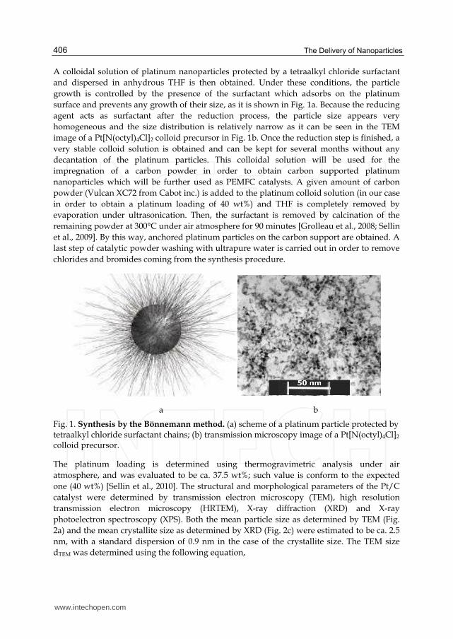
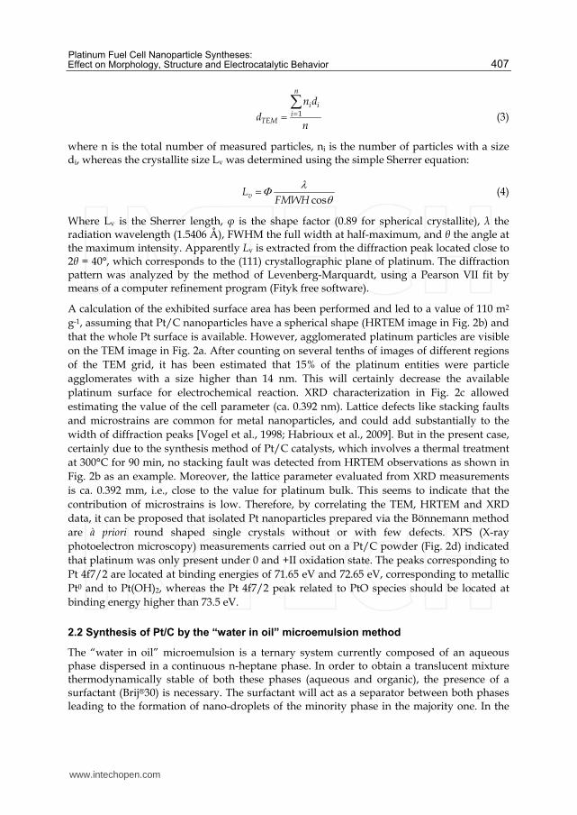
A colloidal solution of platinum nanoparticles protected by a tetraalkyl chloride surfactant and dispersed in anhydrous THF is then obtained. Under these conditions, the particle growth is controlled by the presence of the surfactant which adsorbs on the platinum surface and prevents any growth of their size, as it is shown in Fig. 1a. Because the reducing agent acts as surfactant after the reduction process, the particle size appears very homogeneous and the size distribution is relatively narrow as it can be seen in the TEM image of a Pt[N(octyl)4Cl]2 colloid precursor in Fig. 1b. Once the reduction step is finished, a very stable colloid solution is obtained and can be kept for several months without any decantation of the platinum particles. This colloidal solution will be used for the impregnation of a carbon powder in order to obtain carbon supported platinum nanoparticles which will be further used as PEMFC catalysts. A given amount of carbon powder (Vulcan XC72 from Cabot inc.) is added to the platinum colloid solution (in our case in order to obtain a platinum loading of 40 wt%) and THF is completely removed by evaporation under ultrasonication. Then, the surfactant is removed by calcination of the remaining powder at 300°C under air atmosphere for 90 minutes [Grolleau et al., 2008; Sellin et al., 2009]. By this way, anchored platinum particles on the carbon support are obtained. A last step of catalytic powder washing with ultrapure water is carried out in order to remove chlorides and bromides coming from the synthesis procedure.
a b
Fig. 1. Synthesis by the Bönnemann method. (a) scheme of a platinum particle protected by tetraalkyl chloride surfactant chains; (b) transmission microscopy image of a Pt[N(octyl)4Cl]2 colloid precursor.
The platinum loading is determined using thermogravimetric analysis under air atmosphere, and was evaluated to be ca. 37.5 wt%; such value is conform to the expected one (40 wt%) [Sellin et al., 2010]. The structural and morphological parameters of the Pt/C catalyst were determined by transmission electron microscopy (TEM), high resolution transmission electron microscopy (HRTEM), X-ray diffraction (XRD) and X-ray photoelectron spectroscopy (XPS). Both the mean particle size as determined by TEM (Fig. 2a) and the mean crystallite size as determined by XRD (Fig. 2c) were estimated to be ca. 2.5 nm, with a standard dispersion of 0.9 nm in the case of the crystallite size. The TEM size dTEM was determined using the following equation,
www.intechopen.com
Platinum Fuel Cell Nanoparticle Syntheses: Effect on Morphology, Structure and Electrocatalytic Behavior
407
1
n
i ii
TEM
n d
dn
(3)
where n is the total number of measured particles, ni is the number of particles with a size di, whereas the crystallite size Lv was determined using the simple Sherrer equation:
cosvL
FMWH
(4)
Where Lv is the Sherrer length, φ is the shape factor (0.89 for spherical crystallite), λ the radiation wavelength (1.5406 Å), FWHM the full width at half-maximum, and θ the angle at the maximum intensity. Apparently Lv is extracted from the diffraction peak located close to 2θ = 40°, which corresponds to the (111) crystallographic plane of platinum. The diffraction pattern was analyzed by the method of Levenberg-Marquardt, using a Pearson VII fit by means of a computer refinement program (Fityk free software).
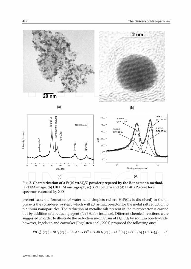
A calculation of the exhibited surface area has been performed and led to a value of 110 m2 g-1, assuming that Pt/C nanoparticles have a spherical shape (HRTEM image in Fig. 2b) and that the whole Pt surface is available. However, agglomerated platinum particles are visible on the TEM image in Fig. 2a. After counting on several tenths of images of different regions of the TEM grid, it has been estimated that 15% of the platinum entities were particle agglomerates with a size higher than 14 nm. This will certainly decrease the available platinum surface for electrochemical reaction. XRD characterization in Fig. 2c allowed estimating the value of the cell parameter (ca. 0.392 nm). Lattice defects like stacking faults and microstrains are common for metal nanoparticles, and could add substantially to the width of diffraction peaks [Vogel et al., 1998; Habrioux et al., 2009]. But in the present case, certainly due to the synthesis method of Pt/C catalysts, which involves a thermal treatment at 300°C for 90 min, no stacking fault was detected from HRTEM observations as shown in Fig. 2b as an example. Moreover, the lattice parameter evaluated from XRD measurements is ca. 0.392 mm, i.e., close to the value for platinum bulk. This seems to indicate that the contribution of microstrains is low. Therefore, by correlating the TEM, HRTEM and XRD data, it can be proposed that isolated Pt nanoparticles prepared via the Bönnemann method are à priori round shaped single crystals without or with few defects. XPS (X-ray photoelectron microscopy) measurements carried out on a Pt/C powder (Fig. 2d) indicated that platinum was only present under 0 and +II oxidation state. The peaks corresponding to Pt 4f7/2 are located at binding energies of 71.65 eV and 72.65 eV, corresponding to metallic Pt0 and to Pt(OH)2, whereas the Pt 4f7/2 peak related to PtO species should be located at binding energy higher than 73.5 eV.
2.2 Synthesis of Pt/C by the “water in oil” microemulsion method
The “water in oil” microemulsion is a ternary system currently composed of an aqueous phase dispersed in a continuous n-heptane phase. In order to obtain a translucent mixture thermodynamically stable of both these phases (aqueous and organic), the presence of a surfactant (Brij®30) is necessary. The surfactant will act as a separator between both phases leading to the formation of nano-droplets of the minority phase in the majority one. In the
www.intechopen.com
The Delivery of Nanoparticles
408
(a)
(b)
(c)
(d)
Fig. 2. Charaterization of a Pt(40 wt.%)/C powder prepared by the Bönnemann method. (a) TEM image, (b) HRTEM micrograph, (c) XRD pattern and (d) Pt 4f XPS core level spectrum recorded by XPS.
present case, the formation of water nano-droplets (where H2PtCl6 is dissolved) in the oil phase is the considered system, which will act as microreactor for the metal salt reduction to platinum nanoparticles. The reduction of metallic salt present in the microreactor is carried out by addition of a reducing agent (NaBH4 for instance). Different chemical reactions were suggested in order to illustrate the reduction mechanism of H2PtCl6 by sodium borohydride; however, Ingelsten and coworker [Ingelsten et al., 2001] proposed the following one:
2 06 4 2 2 3 2( .) ( .) 3 ( .) 4 ( .) 6 ( .) 2 ( )PtCl aq BH aq H O Pt H BO aq H aq Cl aq H g (5)
20 nm
www.intechopen.com
Platinum Fuel Cell Nanoparticle Syntheses: Effect on Morphology, Structure and Electrocatalytic Behavior
409
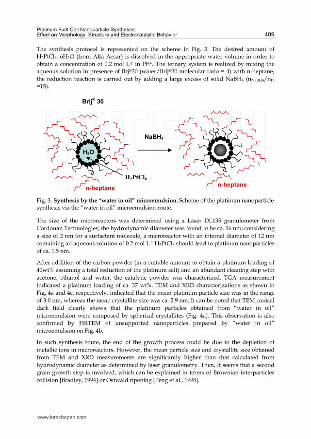
The synthesis protocol is represented on the scheme in Fig. 3. The desired amount of H2PtCl6, 6H2O (from Alfa Aesar) is dissolved in the appropriate water volume in order to obtain a concentration of 0.2 mol L-1 in Pt4+. The ternary system is realized by mixing the aqueous solution in presence of Brj®30 (water/Brij®30 molecular ratio = 4) with n-heptane; the reduction reaction is carried out by adding a large excess of solid NaBH4 (nNaBH4/nPt =15).
Fig. 3. Synthesis by the “water in oil” microemulsion. Scheme of the platinum nanoparticle synthesis via the “water in oil” microemulsion route.
The size of the microreactors was determined using a Laser DL135 granulometer from Cordouan Technologies; the hydrodynamic diameter was found to be ca. 16 nm; considering a size of 2 nm for a surfactant molecule, a microreactor with an internal diameter of 12 nm containing an aqueous solution of 0.2 mol L-1 H2PtCl6 should lead to platinum nanoparticles of ca. 1.5 nm.
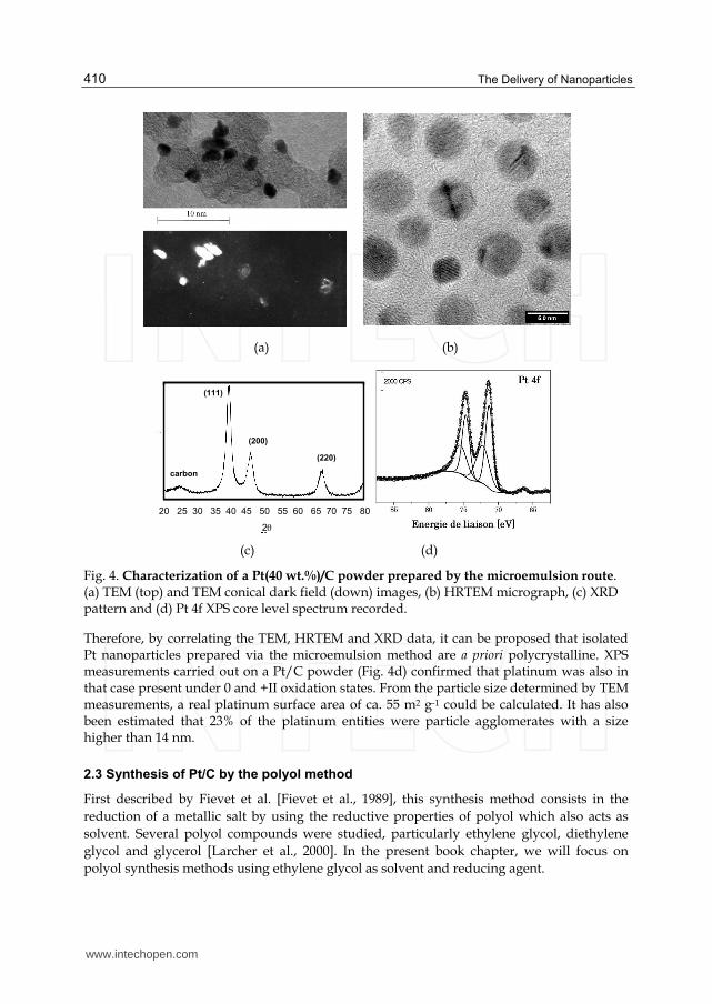
After addition of the carbon powder (in a suitable amount to obtain a platinum loading of 40wt% assuming a total reduction of the platinum salt) and an abundant cleaning step with acetone, ethanol and water, the catalytic powder was characterized. TGA measurement indicated a platinum loading of ca. 37 wt%. TEM and XRD characterizations as shown in Fig. 4a and 4c, respectively, indicated that the mean platinum particle size was in the range of 3.0 nm, whereas the mean crystallite size was ca. 2.9 nm. It can be noted that TEM conical dark field clearly shows that the platinum particles obtained from “water in oil” microemulsion were composed by spherical crystallites (Fig. 4a). This observation is also confirmed by HRTEM of unsupported nanoparticles prepared by “water in oil” microemulsion on Fig. 4b.
In such synthesis route, the end of the growth process could be due to the depletion of metallic ions in microreactors. However, the mean particle size and crystallite size obtained from TEM and XRD measurements are significantly higher than that calculated from hydrodynamic diameter as determined by laser granulometry. Then, It seems that a second grain growth step is involved, which can be explained in terms of Brownian interparticles collision [Bradley, 1994] or Ostwald ripening [Peng et al., 1998].
H2O
n-heptane
Brij® 30
NaBH4
n-heptane
H2PtCl6
www.intechopen.com
The Delivery of Nanoparticles
410
(a) (b)
20 25 30 35 40 45 50 55 60 65 70 75 80
2
(111)
(200)
(220)
carbon
20 25 30 35 40 45 50 55 60 65 70 75 80
2
(111)
(200)
(220)
carbon
(c) (d)
Fig. 4. Characterization of a Pt(40 wt.%)/C powder prepared by the microemulsion route. (a) TEM (top) and TEM conical dark field (down) images, (b) HRTEM micrograph, (c) XRD pattern and (d) Pt 4f XPS core level spectrum recorded.
Therefore, by correlating the TEM, HRTEM and XRD data, it can be proposed that isolated Pt nanoparticles prepared via the microemulsion method are a priori polycrystalline. XPS measurements carried out on a Pt/C powder (Fig. 4d) confirmed that platinum was also in that case present under 0 and +II oxidation states. From the particle size determined by TEM measurements, a real platinum surface area of ca. 55 m2 g-1 could be calculated. It has also been estimated that 23% of the platinum entities were particle agglomerates with a size higher than 14 nm.
2.3 Synthesis of Pt/C by the polyol method
First described by Fievet et al. [Fievet et al., 1989], this synthesis method consists in the reduction of a metallic salt by using the reductive properties of polyol which also acts as solvent. Several polyol compounds were studied, particularly ethylene glycol, diethylene glycol and glycerol [Larcher et al., 2000]. In the present book chapter, we will focus on polyol synthesis methods using ethylene glycol as solvent and reducing agent.
www.intechopen.com
Platinum Fuel Cell Nanoparticle Syntheses: Effect on Morphology, Structure and Electrocatalytic Behavior
411
Once the metallic salt is completely dissolved in an alkaline solution of ethylene glycol, intermediate phase of metal oxides or hydroxides are created. Then, the dehydration reaction of glycerol into acetaldehyde occurs, which allows the reduction reaction of metal oxides or hydroxides. The reaction mechanism is summarized in equations 6 to 8 [Larcher et al., 2000].
CH2OH-CH2OH CH3-CHO + H2 dehydration reaction (6)
CH2OH-CH2OH + 2OH- CH2O--CH2O- + H2O acid-base reaction (pKa = 6.5) (7)
MO2 + 4 CH3-CHO M + 2 CH3-CO-CO-CH3 + 2 H2O reduction reaction (8)
This reduction reaction under relatively soft conditions favours low grain growth kinetics. The grain growth process is stopped due to the combination of two phenomena: adsorption of reaction by-products on the metal surface (particularly glycolates formed in alkaline medium according to equation 7) and depletion of metal salt to be reduced. Moreover, glycolate ligands, which also act as surfactant, do interact weakly and adsorbs preferentially on certain crystalline surface domains of platinum particles, so that nanoparticles with surface orientations (facetted) can be created.
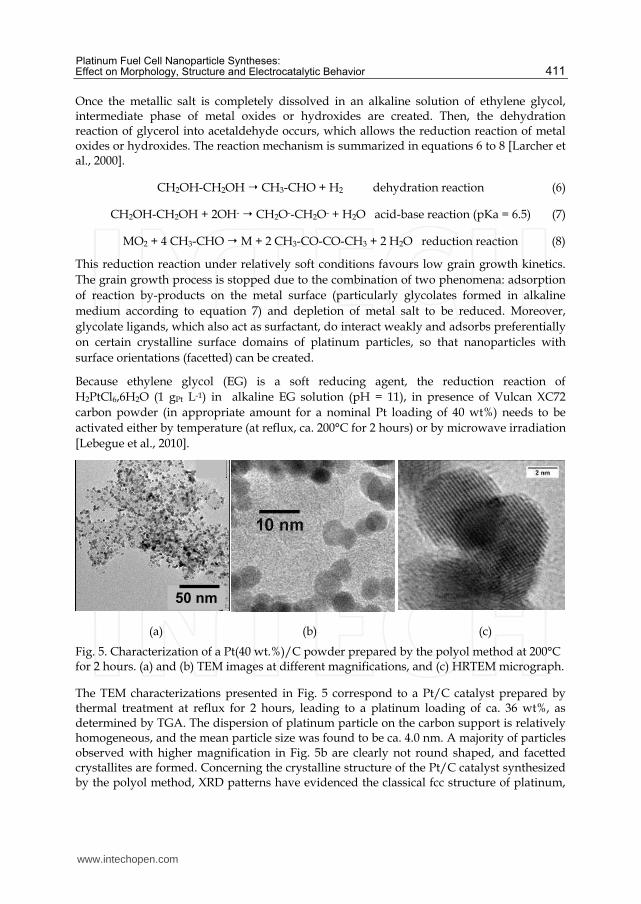
Because ethylene glycol (EG) is a soft reducing agent, the reduction reaction of H2PtCl6,6H2O (1 gPt L-1) in alkaline EG solution (pH = 11), in presence of Vulcan XC72 carbon powder (in appropriate amount for a nominal Pt loading of 40 wt%) needs to be activated either by temperature (at reflux, ca. 200°C for 2 hours) or by microwave irradiation [Lebegue et al., 2010].
(a) (b) (c)
Fig. 5. Characterization of a Pt(40 wt.%)/C powder prepared by the polyol method at 200°C for 2 hours. (a) and (b) TEM images at different magnifications, and (c) HRTEM micrograph.
The TEM characterizations presented in Fig. 5 correspond to a Pt/C catalyst prepared by thermal treatment at reflux for 2 hours, leading to a platinum loading of ca. 36 wt%, as determined by TGA. The dispersion of platinum particle on the carbon support is relatively homogeneous, and the mean particle size was found to be ca. 4.0 nm. A majority of particles observed with higher magnification in Fig. 5b are clearly not round shaped, and facetted crystallites are formed. Concerning the crystalline structure of the Pt/C catalyst synthesized by the polyol method, XRD patterns have evidenced the classical fcc structure of platinum,
50 nm
www.intechopen.com
The Delivery of Nanoparticles
412
from which the determined cell parameter was found to be close to that of bulk platinum (i.e. 0.392 nm) for a mean crystallite size of ca. 4 nm. The isolated nanoparticles would then correspond to single nanocrystals dispersed on the carbon substrate. This assumption is confirmed by the HRTEM image presented in Fig. 5c, where isolated particles appear really as single crystals.
2.4 Synthesis of Pt/C by the "instant method"
In order to obtain a high dispersion and prevent any undesirable nanoparticle agglomeration, a surfactant is commonly used in the chemical synthesis methods of platinum catalysts. This molecule controls the seed formation as well as its growth through the reduction of the metal salt. But its stabilizing effect depends on the pH and the temperature of the solution. As can be seen in the methods cited above, various molecules are proposed as surfactants for catalyst preparation. Reetz et al. [Reetz and Koch, 1998; Reetz and Koch, 1999] have shown that the use of a surfactant permits to produce metal oxides as intermediate species before their reduction to catalysts. Indeed, alkaline solutions such as NaOH, Na2CO3, or Li2CO3 are added to the platinum salts (PtCl4 or H2PtCl6) in presence of water-soluble betaine stabilizer (3-(N,N-dimethyldodecylammonio)propane sulfonate [R(CH3)2N+(CH3)3SO3
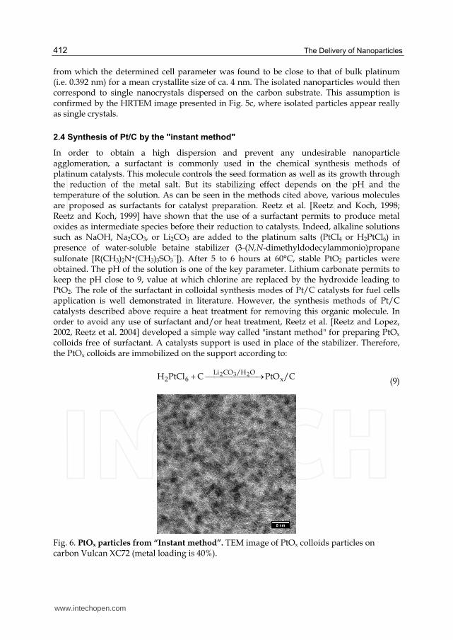
]). After 5 to 6 hours at 60°C, stable PtO2 particles were obtained. The pH of the solution is one of the key parameter. Lithium carbonate permits to keep the pH close to 9, value at which chlorine are replaced by the hydroxide leading to PtO2. The role of the surfactant in colloidal synthesis modes of Pt/C catalysts for fuel cells application is well demonstrated in literature. However, the synthesis methods of Pt/C catalysts described above require a heat treatment for removing this organic molecule. In order to avoid any use of surfactant and/or heat treatment, Reetz et al. [Reetz and Lopez, 2002, Reetz et al. 2004] developed a simple way called "instant method" for preparing PtOx colloids free of surfactant. A catalysts support is used in place of the stabilizer. Therefore, the PtOx colloids are immobilized on the support according to:
/CPtOCPtClH xO/HCOLi
62232 (9)
Fig. 6. PtOx particles from “Instant method”. TEM image of PtOx colloids particles on carbon Vulcan XC72 (metal loading is 40%).
www.intechopen.com
Platinum Fuel Cell Nanoparticle Syntheses: Effect on Morphology, Structure and Electrocatalytic Behavior
413
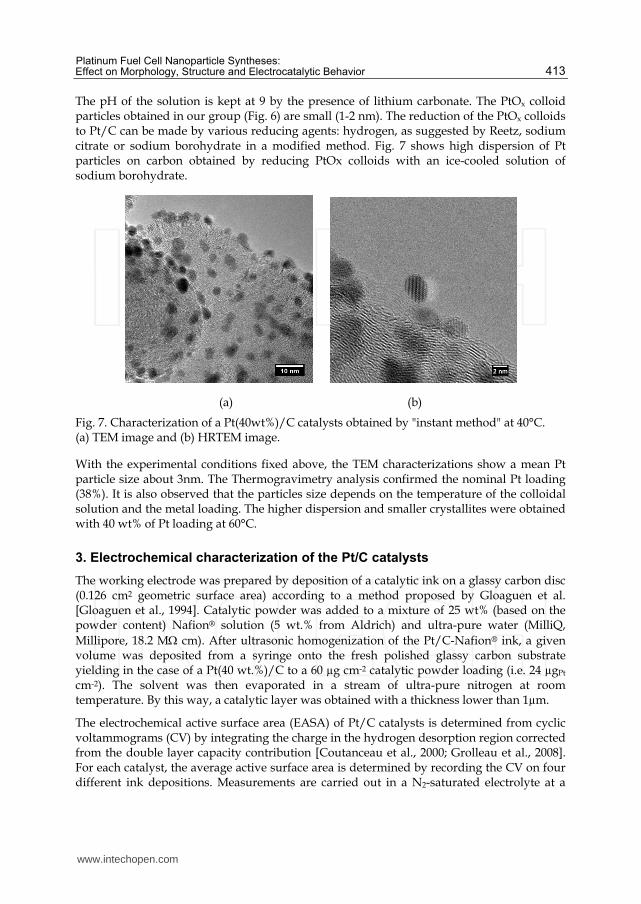
The pH of the solution is kept at 9 by the presence of lithium carbonate. The PtOx colloid particles obtained in our group (Fig. 6) are small (1-2 nm). The reduction of the PtOx colloids to Pt/C can be made by various reducing agents: hydrogen, as suggested by Reetz, sodium citrate or sodium borohydrate in a modified method. Fig. 7 shows high dispersion of Pt particles on carbon obtained by reducing PtOx colloids with an ice-cooled solution of sodium borohydrate.
(a) (b)
Fig. 7. Characterization of a Pt(40wt%)/C catalysts obtained by "instant method" at 40°C. (a) TEM image and (b) HRTEM image.
With the experimental conditions fixed above, the TEM characterizations show a mean Pt particle size about 3nm. The Thermogravimetry analysis confirmed the nominal Pt loading (38%). It is also observed that the particles size depends on the temperature of the colloidal solution and the metal loading. The higher dispersion and smaller crystallites were obtained with 40 wt% of Pt loading at 60°C.
3. Electrochemical characterization of the Pt/C catalysts
The working electrode was prepared by deposition of a catalytic ink on a glassy carbon disc (0.126 cm2 geometric surface area) according to a method proposed by Gloaguen et al. [Gloaguen et al., 1994]. Catalytic powder was added to a mixture of 25 wt% (based on the powder content) Nafion® solution (5 wt.% from Aldrich) and ultra-pure water (MilliQ, Millipore, 18.2 M cm). After ultrasonic homogenization of the Pt/C-Nafion® ink, a given volume was deposited from a syringe onto the fresh polished glassy carbon substrate yielding in the case of a Pt(40 wt.%)/C to a 60 µg cm-2 catalytic powder loading (i.e. 24 µgPt cm-2). The solvent was then evaporated in a stream of ultra-pure nitrogen at room temperature. By this way, a catalytic layer was obtained with a thickness lower than 1µm.
The electrochemical active surface area (EASA) of Pt/C catalysts is determined from cyclic voltammograms (CV) by integrating the charge in the hydrogen desorption region corrected from the double layer capacity contribution [Coutanceau et al., 2000; Grolleau et al., 2008]. For each catalyst, the average active surface area is determined by recording the CV on four different ink depositions. Measurements are carried out in a N2-saturated electrolyte at a
www.intechopen.com
The Delivery of Nanoparticles
414
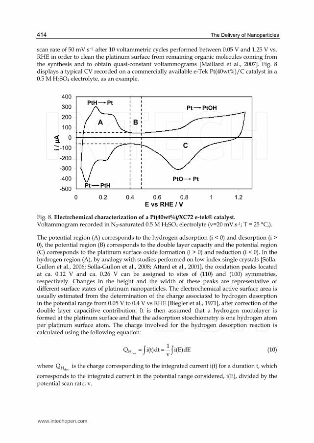
scan rate of 50 mV s−1 after 10 voltammetric cycles performed between 0.05 V and 1.25 V vs. RHE in order to clean the platinum surface from remaining organic molecules coming from the synthesis and to obtain quasi-constant voltammograms [Maillard et al., 2007]. Fig. 8 displays a typical CV recorded on a commercially available e-Tek Pt(40wt%)/C catalyst in a 0.5 M H2SO4 electrolyte, as an example.
-500
-400
-300
-200
-100
0
100
200
300
400
0 0.2 0.4 0.6 0.8 1 1.2
E vs RHE / V
i / µ
A
PtH Pt
A
Pt PtH
B
Pt PtOH
PtO Pt
C
Fig. 8. Electrchemical characterization of a Pt(40wt%)/XC72 e-tek® catalyst. Voltammogram recorded in N2-saturated 0.5 M H2SO4 electrolyte (v=20 mV.s-1; T = 25 °C,).
The potential region (A) corresponds to the hydrogen adsorption (i < 0) and desorption (i > 0), the potential region (B) corresponds to the double layer capacity and the potential region (C) corresponds to the platinum surface oxide formation (i > 0) and reduction (i < 0). In the hydrogen region (A), by analogy with studies performed on low index single crystals [Solla-Gullon et al., 2006; Solla-Gullon et al., 2008; Attard et al., 2001], the oxidation peaks located at ca. 0.12 V and ca. 0.26 V can be assigned to sites of (110) and (100) symmetries, respectively. Changes in the height and the width of these peaks are representative of different surface states of platinum nanoparticles. The electrochemical active surface area is usually estimated from the determination of the charge associated to hydrogen desorption in the potential range from 0.05 V to 0.4 V vs RHE [Biegler et al., 1971], after correction of the double layer capacitive contribution. It is then assumed that a hydrogen monolayer is formed at the platinum surface and that the adsorption stoechiometry is one hydrogen atom per platinum surface atom. The charge involved for the hydrogen desorption reaction is calculated using the following equation:
desH
1Q i(t)dt i(E)dE
v (10)
where desHQ is the charge corresponding to the integrated current i(t) for a duration t, which
corresponds to the integrated current in the potential range considered, i(E), divided by the potential scan rate, v.
www.intechopen.com
Platinum Fuel Cell Nanoparticle Syntheses: Effect on Morphology, Structure and Electrocatalytic Behavior
415
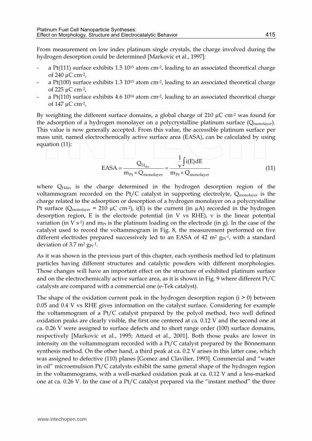
From measurement on low index platinum single crystals, the charge involved during the hydrogen desorption could be determined [Markovic et al., 1997]:
- a Pt(111) surface exhibits 1.5 1015 atom cm-2, leading to an associated theoretical charge of 240 µC cm-2,
- a Pt(100) surface exhibits 1.3 1015 atom cm-2, leading to an associated theoretical charge of 225 µC cm-2,
- a Pt(110) surface exhibits 4.6 1014 atom cm-2, leading to an associated theoretical charge of 147 µC cm-2,
By weighting the different surface domains, a global charge of 210 µC cm-2 was found for the adsorption of a hydrogen monolayer on a polycrystalline platinum surface (Qmonolayer). This value is now generally accepted. From this value, the accessible platinum surface per mass unit, named electrochemically active surface area (EASA), can be calculated by using equation (11):
desH
Pt monolayer Pt monolayer
1 i(E)dEQ vEASAm Q m Q
(11)
where QHdes is the charge determined in the hydrogen desorption region of the voltammogram recorded on the Pt/C catalyst in supporting electrolyte, Qmonolayer is the charge related to the adsorption or desorption of a hydrogen monolayer on a polycrystalline Pt surface (Qmonolayer = 210 µC cm-2), i(E) is the current (in µA) recorded in the hydrogen desorption region, E is the electrode potential (in V vs RHE), v is the linear potential variation (in V s-1) and mPt is the platinum loading on the electrode (in g). In the case of the catalyst used to record the voltammogram in Fig. 8, the measurement performed on five different electrodes prepared successively led to an EASA of 42 m2 gPt-1, with a standard deviation of 3.7 m2 gPt-1.
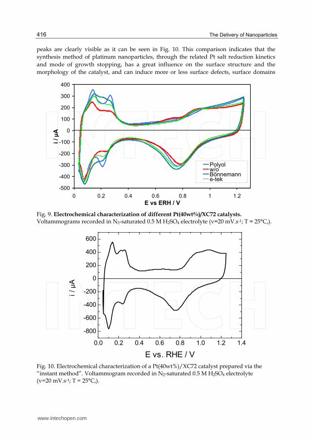
As it was shown in the previous part of this chapter, each synthesis method led to platinum particles having different structures and catalytic powders with different morphologies. Those changes will have an important effect on the structure of exhibited platinum surface and on the electrochemically active surface area, as it is shown in Fig. 9 where different Pt/C catalysts are compared with a commercial one (e-Tek catalyst).
The shape of the oxidation current peak in the hydrogen desorption region (i > 0) between 0.05 and 0.4 V vs RHE gives information on the catalyst surface. Considering for example the voltammogram of a Pt/C catalyst prepared by the polyol method, two well defined oxidation peaks are clearly visible, the first one centered at ca. 0.12 V and the second one at ca. 0.26 V were assigned to surface defects and to short range order (100) surface domains, respectively [Markovic et al., 1995; Attard et al., 2001]. Both those peaks are lower in intensity on the voltammogram recorded with a Pt/C catalyst prepared by the Bönnemann synthesis method. On the other hand, a third peak at ca. 0.2 V arises in this latter case, which was assigned to defective (110) planes [Gomez and Clavilier, 1993]. Commercial and “water in oil” microemulsion Pt/C catalysts exhibit the same general shape of the hydrogen region in the voltammograms, with a well-marked oxidation peak at ca. 0.12 V and a less-marked one at ca. 0.26 V. In the case of a Pt/C catalyst prepared via the “instant method” the three
www.intechopen.com
The Delivery of Nanoparticles
416
peaks are clearly visible as it can be seen in Fig. 10. This comparison indicates that the synthesis method of platinum nanoparticles, through the related Pt salt reduction kinetics and mode of growth stopping, has a great influence on the surface structure and the morphology of the catalyst, and can induce more or less surface defects, surface domains
-500
-400
-300
-200
-100
0
100
200
300
400
0 0.2 0.4 0.6 0.8 1 1.2
E vs ERH / V
i /
µA
Polyolw/oBönnemanne-tek
Fig. 9. Electrochemical characterization of different Pt(40wt%)/XC72 catalysts. Voltammograms recorded in N2-saturated 0.5 M H2SO4 electrolyte (v=20 mV.s-1; T = 25°C,).
Fig. 10. Electrochemical characterization of a Pt(40wt%)/XC72 catalyst prepared via the “instant method”. Voltammogram recorded in N2-saturated 0.5 M H2SO4 electrolyte (v=20 mV.s-1; T = 25°C,).
www.intechopen.com
Platinum Fuel Cell Nanoparticle Syntheses: Effect on Morphology, Structure and Electrocatalytic Behavior
417
and surface heterogeneities. It is also likely that such changes in morphology and structure could lead to changes in the catalytic activity of the different Pt/C catalysts.
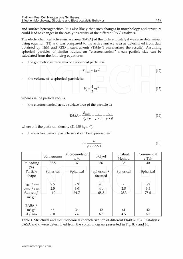
The electrochemical active surface area (EASA) of the different catalyst was also determined using equation (11) and was compared to the active surface area as determined from data obtained by TEM and XRD measurements (Table 1 summarizes the results). Assuming spherical particles of similar radius, an “electrochemical” mean particle size can be calculated from the following equations:
- the geometric surface area of a spherical particle is:
24geomS r (12)
- the volume of a spherical particle is:
343pV r (13)
where r is the particle radius.
- the electrochemical active surface area of the particle is:
3 6geom
p
SEASA
V r d (14)
where is the platinum density (21 450 kg m-3).
- the electrochemical particle size d can be expressed as:
6
dEASA (15)
Bönnemann Microemulsion w/o
Polyol Instant Method
Commercial e-Tek
Pt loading (%)
Particle shape
dXRD / nm dTEM / nm Sreal,TEM /
m2 g-1
EASA / m2 g-1
d / nm
37.5
Spherical
2.5 2.5 110
46 6.0
37
Spherical
2.9 3.0
91.7
34 7.6
36
spherical + facetted
4.0 4.0 68.8
42 6.5
38
Spherical -
2.8 98.3
61 4.5
40
Spherical
3.2 3.5
78.6
42 6.5
Table 1. Structural and electrochemical characterization of different Pt(40 wt%)/C catalysts; EASA and d were determined from the voltammogram presented in Fig. 8, 9 and 10.
www.intechopen.com
The Delivery of Nanoparticles
418
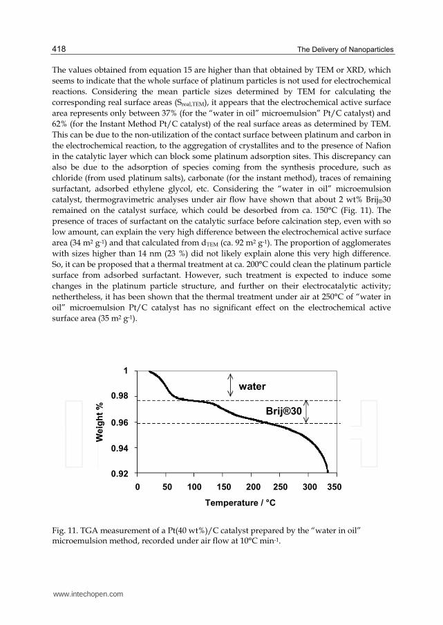
The values obtained from equation 15 are higher than that obtained by TEM or XRD, which seems to indicate that the whole surface of platinum particles is not used for electrochemical reactions. Considering the mean particle sizes determined by TEM for calculating the corresponding real surface areas (Sreal,TEM), it appears that the electrochemical active surface area represents only between 37% (for the “water in oil” microemulsion” Pt/C catalyst) and 62% (for the Instant Method Pt/C catalyst) of the real surface areas as determined by TEM. This can be due to the non-utilization of the contact surface between platinum and carbon in the electrochemical reaction, to the aggregation of crystallites and to the presence of Nafion in the catalytic layer which can block some platinum adsorption sites. This discrepancy can also be due to the adsorption of species coming from the synthesis procedure, such as chloride (from used platinum salts), carbonate (for the instant method), traces of remaining surfactant, adsorbed ethylene glycol, etc. Considering the “water in oil” microemulsion catalyst, thermogravimetric analyses under air flow have shown that about 2 wt% Brij®30 remained on the catalyst surface, which could be desorbed from ca. 150°C (Fig. 11). The presence of traces of surfactant on the catalytic surface before calcination step, even with so low amount, can explain the very high difference between the electrochemical active surface area (34 m2 g-1) and that calculated from dTEM (ca. 92 m2 g-1). The proportion of agglomerates with sizes higher than 14 nm (23 %) did not likely explain alone this very high difference. So, it can be proposed that a thermal treatment at ca. 200°C could clean the platinum particle surface from adsorbed surfactant. However, such treatment is expected to induce some changes in the platinum particle structure, and further on their electrocatalytic activity; nethertheless, it has been shown that the thermal treatment under air at 250°C of “water in oil” microemulsion Pt/C catalyst has no significant effect on the electrochemical active surface area (35 m2 g-1).
water
Brij®30
0 50 100 150 200 250 300 350
Temperature / °C
1
0.98
0.96
0.94
0.92
We
igh
t%
water
Brij®30
0 50 100 150 200 250 300 350
Temperature / °C
1
0.98
0.96
0.94
0.92
We
igh
t%
Fig. 11. TGA measurement of a Pt(40 wt%)/C catalyst prepared by the “water in oil” microemulsion method, recorded under air flow at 10°C min-1.
www.intechopen.com
Platinum Fuel Cell Nanoparticle Syntheses: Effect on Morphology, Structure and Electrocatalytic Behavior
419
0.0 0.2 0.4 0.6 0.8 1.0 1.20
2
4
6
8
10j
/ m
A c
m-2
E vs RHE / V
0.0 0.2 0.4 0.6 0.8 1.0 1.20
2
4
6
8
10
j / m
A c
m-2
E vs RHE / V
0.0 0.2 0.4 0.6 0.8 1.0 1.20
5
10
15
20
j / m
A c
m-2
E vs RHE / V
EG
0.0 0.2 0.4 0.6 0.8 1.0 1.20
5
10
15
j / m
A c
m-2
E vs RHE / V
Instant method
Bönnemann w/o
0.0 0.2 0.4 0.6 0.8 1.0 1.20
2
4
6
8
10j / m
A c
m-2
E vs RHE / V
0.0 0.2 0.4 0.6 0.8 1.0 1.20
2
4
6
8
10
j / m
A c
m-2
E vs RHE / V
0.0 0.2 0.4 0.6 0.8 1.0 1.20
5
10
15
20
j / m
A c
m-2
E vs RHE / V
EG
0.0 0.2 0.4 0.6 0.8 1.0 1.20
5
10
15
j / m
A c
m-2
E vs RHE / V
Instant method
Bönnemann w/o
0.0 0.2 0.4 0.6 0.8 1.0 1.20
5
10
15
20
j / m
A c
m-2
E vs RHE / V
EG
0.0 0.2 0.4 0.6 0.8 1.0 1.20
5
10
15
20
j / m
A c
m-2
E vs RHE / V
EG
0.0 0.2 0.4 0.6 0.8 1.0 1.20
5
10
15
j / m
A c
m-2
E vs RHE / V
Instant method
0.0 0.2 0.4 0.6 0.8 1.0 1.20
5
10
15
j / m
A c
m-2
E vs RHE / V
Instant method
Bönnemann w/o
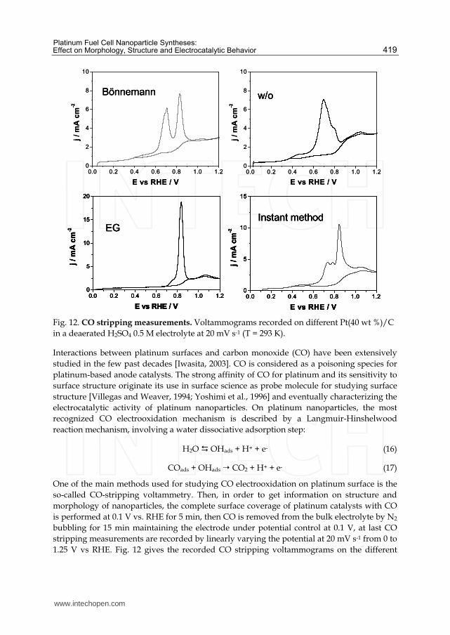
Fig. 12. CO stripping measurements. Voltammograms recorded on different Pt(40 wt %)/C in a deaerated H2SO4 0.5 M electrolyte at 20 mV s-1 (T = 293 K).
Interactions between platinum surfaces and carbon monoxide (CO) have been extensively studied in the few past decades [Iwasita, 2003]. CO is considered as a poisoning species for platinum-based anode catalysts. The strong affinity of CO for platinum and its sensitivity to surface structure originate its use in surface science as probe molecule for studying surface structure [Villegas and Weaver, 1994; Yoshimi et al., 1996] and eventually characterizing the electrocatalytic activity of platinum nanoparticles. On platinum nanoparticles, the most recognized CO electrooxidation mechanism is described by a Langmuir-Hinshelwood reaction mechanism, involving a water dissociative adsorption step:
H2O OHads + H+ + e- (16)
COads + OHads CO2 + H+ + e- (17)
One of the main methods used for studying CO electrooxidation on platinum surface is the so-called CO-stripping voltammetry. Then, in order to get information on structure and morphology of nanoparticles, the complete surface coverage of platinum catalysts with CO is performed at 0.1 V vs. RHE for 5 min, then CO is removed from the bulk electrolyte by N2 bubbling for 15 min maintaining the electrode under potential control at 0.1 V, at last CO stripping measurements are recorded by linearly varying the potential at 20 mV s-1 from 0 to 1.25 V vs RHE. Fig. 12 gives the recorded CO stripping voltammograms on the different
www.intechopen.com
The Delivery of Nanoparticles
420
synthesized catalysts. Clearly, the shape of the CO oxidation current feature is completely different according to the catalyst. The Bönnemann, w/o microemulsion and instant method catalysts, which are round shaped catalyst, lead to several oxidation peaks or shoulders, with a more or less important pre-peak from 0.4 to 0.6 V vs. RHE, whereas the polyol catalyst leads to a well defined single oxidation peak (and a small shoulder at lower potentials) and no pre-peak. The electrooxidation of carbon monoxide is often characterized by the existence of multiple oxidation peaks, which was explained either by a platinum particle size effect [Friedrich et al., 2000; Maillard et al., 2004], or by the presence of agglomerates [Maillard et al., 2005; Lopez-Cudero et al., 2010], or by the presence of grain boundaries [Plyasova et al., 2006] or again by surface crystallographic domain structures [Solla-Gullon et al., 2006; Solla-Gullon et al., 2008; Brimaud et al., 2008]. However, in the case of the catalysts presented here, the absence of an oxidation peak at ca. 0.7 V in the CO stripping voltammogram of the polyol catalyst could be interpreted by the absence of particle agglomeration according to other authors [Maillard et al., 2005; Lopez-Cudero et al., 2010], although TEM image in Fig. 5a clearly shows the presence of aggregates. Size effect could also hardly be proposed for the existence of the oxidation peak at ca. 0.85 V which was attributed by certain authors to CO oxidation on smaller particles [Friedrich et al., 2000; Maillard et al., 2004], as means particles size are in the same range for Bönnemann, w/o microemulsion and instant method catalysts. These experiments evidenced that the history of the Pt/C catalyst has a great importance on the electrochemical behaviour towards pre-adsorbed CO layer oxidation reaction, which is a well know surface structure sensitive reaction. However, based on current data and knowledge concerning this reaction, it is yet very difficult and too early to rely the electrochemical behavior to a given structure or morphology of a Pt/C catalyst.
4. Electrocatalytic activity towards the oxygen reduction reaction in acid medium
The oxygen reduction reaction is the limiting process in proton exchange fuel cells [Ralph and Hogarth, 2002]; this very irreversible reaction involves indeed the exchange of several electrons, and as a consequence, occurs with a high overvoltage. For this reason it has been extensively studied for the last few decades.
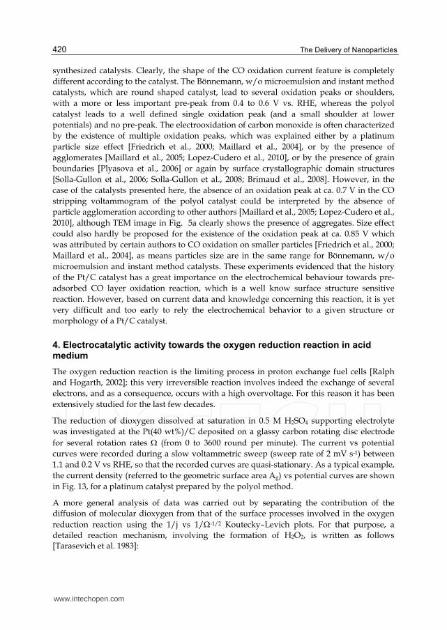
The reduction of dioxygen dissolved at saturation in 0.5 M H2SO4 supporting electrolyte was investigated at the Pt(40 wt%)/C deposited on a glassy carbon rotating disc electrode for several rotation rates (from 0 to 3600 round per minute). The current vs potential curves were recorded during a slow voltammetric sweep (sweep rate of 2 mV s-1) between 1.1 and 0.2 V vs RHE, so that the recorded curves are quasi-stationary. As a typical example, the current density (referred to the geometric surface area Ag) vs potential curves are shown in Fig. 13, for a platinum catalyst prepared by the polyol method.
A more general analysis of data was carried out by separating the contribution of the diffusion of molecular dioxygen from that of the surface processes involved in the oxygen reduction reaction using the 1/j vs 1/-1/2 Koutecky–Levich plots. For that purpose, a detailed reaction mechanism, involving the formation of H2O2, is written as follows [Tarasevich et al. 1983]:
www.intechopen.com
Platinum Fuel Cell Nanoparticle Syntheses: Effect on Morphology, Structure and Electrocatalytic Behavior
421
O2,sol O2,surf diffusion in the bulk electrolyte (diffusion coefficient D) (18)
O2,surf O2,cata diffusion in the catalytic film (limiting current density jlfilm ) (19)
O2,cata O2,ads adsorption process (limiting current density jlads) (20)
O2,ads + 2e- [O2,ads]2- electron transfer rds (exchange current density j0, Tafel slope b) (21)
[O2,ads]2- + H+ [HO2,ads]- (22)
[HO2,ads]- + H+ [H2O2]ads H2O2 (23a)
or [HO2,ads]- + H+ + e- H2O2 (23b)
followed by H2O2 + 2 H+ + 2 e- 2 H2O
Fig. 13. ORR study at a Pt/C catalyst prepared by a polyol method. j(E) polarization curves at different electrode rotation rates in revolution per minute(rpm) recorded in a O2-saturated 0.5 M H2SO4 electrolyte. (T=20°C, scan rate = 2mVs-1).
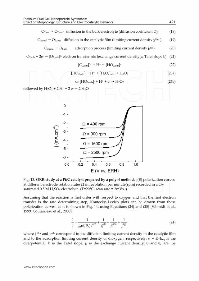
Assuming that the reaction is first order with respect to oxygen and that the first electron transfer is the rate determining step, Koutecky–Levich plots can be drawn from these polarization curves, as it is shown in Fig. 14, using Equations (24) and (25) [Schmidt et al., 1999; Coutanceau et al., 2000]:
0
1 1 1 1 1( ) b ads film diff
le l lj jj e j j (24)
where jlfilm and jlads correspond to the diffusion limiting current density in the catalytic film and to the adsorption limiting current density of dioxygen, respectively; = E−Eeq is the overpotential; b is the Tafel slope; j0 is the exchange current density; and e are the
0.0 0.2 0.4 0.6 0.8 1.0
-6
-5
-4
-3
-2
-1
0
j (m
A.c
m-2)
E (V vs. ERH)
= 400 rpm
= 900 rpm
= 1600 rpm
= 2500 rpm
www.intechopen.com
The Delivery of Nanoparticles
422
coverage of platinum surface by species coming from oxygen adsorption at potential E and at the equilibrium potential Eeq (1.185V vs RHE), respectively, and jldiff is the diffusion limiting current density which can be calculated from the Levich law:
2 2
2 3 1 6 1 20.2diffO Olj nF D C (25)
with n the number of electron exchanged per oxygen molecule, F the Faraday constant (96,500 C mol-1), DO2 the coefficient diffusion of oxygen molecular in 0.5 M H2SO4 (2.1×10⁻⁵ cm2 s-1), the kinematic viscosity of the electrolyte (1.07×10⁻² cm2 s-1), CO2 the bulk concentration of oxygen in a saturated electrolytic solution (1.03×10⁻³ mol L−1) [Jakobs et al., 1985]. The coefficient 0.2 is used when the working electrode rotation rate is expressed in revolutions per minute (rpm) [Bard et al., 2001; Zagal et al., 1980].
0.020 0.025 0.030 0.035 0.040 0.045 0.050
-0.45
-0.40
-0.35
-0.30
-0.25
-0.20
-0.15
0.62 V/RHE
0.65 V/RHE
0.68 V/RHE
0.70 V/RHE
0.73 V/RHE
0.77 V/RHE
-1/2 / rpm-1/2
j-1
/ cm
2m
A-1
0.020 0.025 0.030 0.035 0.040 0.045 0.050
-0.45
-0.40
-0.35
-0.30
-0.25
-0.20
-0.15
0.62 V/RHE
0.65 V/RHE
0.68 V/RHE
0.70 V/RHE
0.73 V/RHE
0.77 V/RHE
0.020 0.025 0.030 0.035 0.040 0.045 0.050
-0.45
-0.40
-0.35
-0.30
-0.25
-0.20
-0.15
0.62 V/RHE
0.65 V/RHE
0.68 V/RHE
0.70 V/RHE
0.73 V/RHE
0.77 V/RHE
-1/2 / rpm-1/2
j-1
/ cm
2m
A-1
Fig. 14. ORR study at a Pt/C catalyst prepared by a polyol method. Koutecky–Levich plots at different potentials determined from j(E) curves presented in Fig. 12.
The film diffusion limiting current density and the adsorption limiting current density are both independent on disk electrode rotation rates and applied potential (E), thus it is impossible to dissociate them. Then, the current density j can be expressed as follows:
0
1 1 1 1( ) b diff
le lj jj e j with
1 1 1ads film
l l lj j j (26)
Assuming that in the considered potential range the adsorption process of oxygen is more rapid than the charge transfer step, i. e. ≈ e for the whole electrode potential range [Coutanceau et al., 2001]. The kinetic current density jk can be expressed as:
0
1 1 1b
k lj jj e (27)
www.intechopen.com
Platinum Fuel Cell Nanoparticle Syntheses: Effect on Morphology, Structure and Electrocatalytic Behavior
423
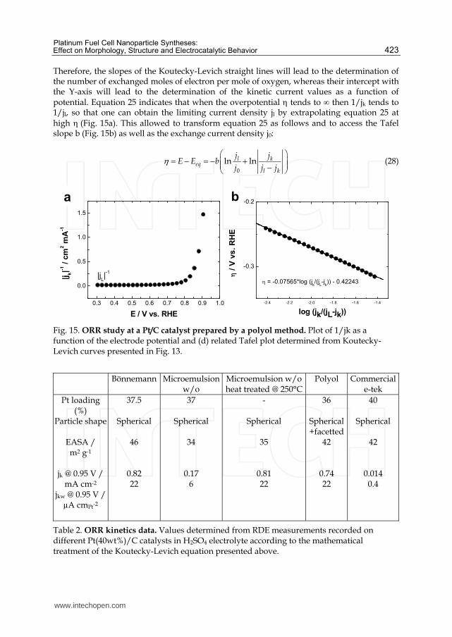
Therefore, the slopes of the Koutecky-Levich straight lines will lead to the determination of the number of exchanged moles of electron per mole of oxygen, whereas their intercept with the Y-axis will lead to the determination of the kinetic current values as a function of potential. Equation 25 indicates that when the overpotential tends to ∞ then 1/jk tends to 1/jl, so that one can obtain the limiting current density jl by extrapolating equation 25 at high (Fig. 15a). This allowed to transform equation 25 as follows and to access the Tafel slope b (Fig. 15b) as well as the exchange current density j0:
0
ln lnl keq
l k
j jE E b
j j j (28)
Fig. 15. ORR study at a Pt/C catalyst prepared by a polyol method. Plot of 1/jk as a function of the electrode potential and (d) related Tafel plot determined from Koutecky-Levich curves presented in Fig. 13.
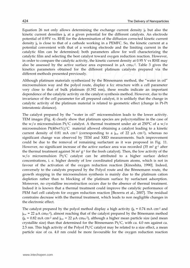
Bönnemann Microemulsion w/o
Microemulsion w/o heat treated @ 250°C
Polyol Commercial e-tek
Pt loading (%)
Particle shape
EASA / m2 g-1
jk @ 0.95 V /
mA cm-2 jkw @ 0.95 V /
µA cmPt-2
37.5
Spherical
46
0.82 22
37
Spherical
34
0.17 6
-
Spherical
35
0.81 22
36
Spherical+facetted
42
0.74 22
40
Spherical
42
0.014 0.4
Table 2. ORR kinetics data. Values determined from RDE measurements recorded on different Pt(40wt%)/C catalysts in H2SO4 electrolyte according to the mathematical treatment of the Koutecky-Levich equation presented above.
-2.4 -2.2 -2.0 -1.8 -1.6 -1.4
-0.3
-0.2(d)
/ V
vs
. R
HE
log (jk/(jL-jk))
= -0.07565*log (jk/(j
L-j
k)) - 0.42243
0.3 0.4 0.5 0.6 0.7 0.8 0.9 1.0
0.0
0.5
1.0
1.5
(c)
|jk|-1
/ c
m2 m
A-1
E / V vs. RHE
|jL|-1
a b
www.intechopen.com
The Delivery of Nanoparticles
424
Equation 26 not only allows determining the exchange current density j0 but also the kinetic current densities jk at a given potential for the different catalysts. An electrode potential of 0.95V vs. RHE for the determination of the diffusion corrected kinetic current density jk is close to that of a cathode working in a PEMFC. So, the kinetic current at a potential convenient with that of a working electrode and the limiting current in the catalytic film can be determined; both parameters allow for well characterizing the catalytic film and selecting the best catalyst toward oxygen reduction reaction. However, in order to compare the catalytic activity, the kinetic current density at 0.95 V vs RHE may also be assessed by the active surface area expressed in µA cmPt-2. Table 3 gives the kinetics parameters obtained for the different platinum catalysts prepared via the different methods presented previously.
Although platinum materials synthesized by the Bönnemann method, the “water in oil” microemulsion way and the polyol route, display a fcc structure with a cell parameter very close to that of bulk platinum (0.392 nm), these results indicate an important dependence of the catalytic activity on the catalyst synthesis method. However, due to the invariance of the cell parameter for all prepared catalyst, it is unlikely that the change in catalytic activity of the platinum material is related to geometric effect (change in Pt-Pt interatomic distance).
The catalyst prepared by the “water in oil” microemulsion leads to the lower activity. TEM images (Fig. 4) clearly show that platinum species are polycrystalline in the case of the w/o microemulsion Pt/C catalyst. A thermal treatment under air at 250°C of a w/o microemulsion Pt(40wt%)/C material allowed obtaining a catalyst leading to a kinetic current density of 0.81 mA cm-2 (corresponding to a jkw of 22 µA cm-2), whereas no significant change was observed by TEM and XRD measurements. Such improvement could be due to the removal of remaining surfactant as it was proposed in Fig. 11. However, no significant increase of the active surface area was recorded (35 m2 g-1 after the thermal treatment against 34 m2 g-1 for the fresh catalyst). Then, the low activity of the w/o microemulsion Pt/C catalyst can be attributed to a higher surface defect concentrations, i. e. higher density of low coordinated platinum atoms, which is not in favour of the activation of the oxygen reduction reaction [Kinoshita, 1990]. Indeed, conversely to the catalysts prepared by the Polyol route and the Bönnemann route, the growth stopping in the microemulsion synthesis is mainly due to the platinum cation depletion rather than to blocking of the platinum surface by surfactant adsorption. Moreover, no crystalline reconstruction occurs due to the absence of thermal treatment. Indeed it is known that a thermal treatment could improve the catalytic performance of PEM fuel cell catalysts for oxygen reduction reaction [Bezerra et al., 2007]. The residual constrains decrease with the thermal treatment, which leads to non negligible changes in the electronic effect.
The catalyst prepared by the polyol method display a high activity (jk = 0.74 mA cm-2 and jkw = 22 µA cmPt-2), almost reaching that of the catalyst prepared by the Bönemann method (jk = 0.82 mA cm-2 and jkw = 22 µA cmPt-2), although a higher mean particle size (and mean crystallite size) than that determined for the Bönnemann Pt/C, with ca. 4.0 nm against ca. 2.5 nm. This high activity of the Polyol Pt/C catalyst may be related to a size effect, a mean particle size of ca. 4.0 nm could be more favourable for the oxygen reduction reaction
www.intechopen.com
Platinum Fuel Cell Nanoparticle Syntheses: Effect on Morphology, Structure and Electrocatalytic Behavior
425
[Kinoshita, 1990]. It could also be related to the presence of facets on the platinum surface, which could also favour the ORR. Indeed, facets display less low-coordinated surface atoms than edges or corners, which could be blocked by strongly adsorbed oxygen containing species difficult to reduce.
5. Conclusion
This book chapter intended to point out the importance of the Pt/C history on the electrocatalytic activity. For this purpose, different colloidal methods have been developed for the synthesis of platinum-based catalysts for Proton Exchange Membrane Fuel Cell (PEMFC) applications. Such methods are expected to produce metallic nano-sized particles with a narrow size distribution. However, the germination process, the grain growth and the metallic particles stabilization steps leading to Pt-surfactant stabilized colloids were different according to the synthesis route. For example, synthesis performed in organic or aqueous media could sometimes require thermal treatment (Bönnemann method) or not (Instant method). The end of the grain growth mechanism could occur either from depletion of metallic salts in surfactant stabilized nanoreactors (“water in oil” microemulsion method) or from the blocking of the platinum particle surface by adsorption of a surfactant (Bönnemann and polyol methods). All these mechanisms led to reach different catalyst morphologies and structures. The different methods of metal nanocatalyst synthesis via colloidal routes were first described, particularly Bönnemann method, “water in oil” microemulsion, polyol methods with thermal or microwave activation and instant method, in which different mechanisms are involved for the metal nanoparticle formation. Because the reactions occurring in Fuel Cells are known to be sensitive to the catalyst structure, the present book chapter has then focused on the relationship between synthesis methods, catalyst structure and morphology, crystallite microstructure, electrochemical properties and electrocatalytic behaviour of the materials.
The influence on the composite material structure and morphology has been discussed on the basis of microscopy observations (TEM, HRTEM) and X ray measurements (XRD, XPS). The characterization of the catalyst structure (mean sizes and size distribution of isolated particles), of the composite material morphology (mean size and size distribution of aggregates), and the platinum microstructure (crystallinity, crystallite sizes), etc. has also been performed and discussed.
Then, the electrochemical active surface areas, the behavior toward pre-adsorbed CO saturating layer oxidation and the activity toward the oxygen reduction reaction (ORR) have been compared using electrochemical methods (Cyclic voltammetry, rotating disc and ring disc electrodes). In the case of ORR studies, the number of exchanged electrons and the kinetic current densities at 0.95 V vs RHE, as determined from mathematical treatment of the Koutecky-Levich equation, have been used to compare the activity and selectivity of the different Pt/C catalysts. An important dependence of the catalytic activity on the catalyst synthesis method has been evidenced. However, due to the invariance of the cell parameter for all prepared catalyst, it is unlikely that the change in catalytic activity of the platinum material is related to geometric effect (change in Pt-Pt interatomic distance). But, the surface structure, presence of surface domains (facets) or of surface defects, seems also to have an important effect on the catalytic activity. It also seems that a thermal treatment, leading to
www.intechopen.com
The Delivery of Nanoparticles
426
crystallite reconstruction and decrease of residual strains, could lead to an enhancement of the catalytic activity toward orr.
Although the final objective, which was to correlate the activity of Pt/C catalysts to their morphology and structure, is not fully achieved, this book chapter shows unambiguously that the microstructure, macrostructure and morphology of a Pt/C catalyst has a great effect on its electrochemical behaviour toward molecules having energetic interest in fuel cell technology.
6. References
Attard, G. A. Gillies, J. E. Harris, C. A. Jenkins, D. J. Johnston, P. Price, M. A. Watson, D. J. Wells, P. B. (2001). Electrochemical evaluation of the morphology and enantioselectivity of Pt/graphite. Appl. Catal. A : Gen., Vol. 222, N° 1-2, (December 2001) pp. 393-405.
Ayyadurai, S. M. Choi, Y-S. Ganesan, P. Kumaraguru, S. P. Popov. B. N. (2007). Novel PEMFC Cathodes Prepared by Pulse Deposition. J. Electrochem. Soc., Vol. 154, N° 10 (August 2007) pp. B1063-B1073.
Bard, A. J. Faulkner, L. R.. in: Electrochemical Methods: Fundamentals and Applications, 2nd ed., John Wiley & Sons Inc., New York, 2001,.
Bezerra, C. W. B. Zhang, L. Liu, H. Lee, K. Marques, A. L. B. Marques, E. P. Wang, H. Zhang, J. (2007). A review of heat-treatment effects on activity and stability of PEM fuel cell catalysts for oxygen reduction reaction. J. Power Sources, Vol. 173, N° 2 (November 2007) pp. 891-908.
Biegler, T. Rand, D.A.J. Woods, R. (1971). Limiting Oxygen Coverage on Platinized Platinum; Relevance to Determination of Real Platinum Area by Hydrogen Adsorption. J. Electroanal. Chem., Vol. 29, N° 2, (February 1971) pp. 269-277.
Billy, E. Maillard, F. Morin A. Guetaz, L. Emieux, F. Thurier, C. Doppelt, P. Donet, S. Mailley, S. (2010). Impact of ultra-low Pt loadings on the performance of anode/cathode in a proton-exchange membrane fuel cell. J. Power Sources, Vol. 195, N° 9, (May 2010), pp. 2737-2746.
Bönnemann, H. Brijoux, W. (1995). The preparation, characterization and application of organosols of early transition metals. NanoStructured Materials, Vol. 5, N° 2, (February 1995) pp. 135-140.
Bönnemann, H. Brijoux, W. Brinkmann, R. Dinjus, E. Joussen, T. Korall, B. (1991). Formation of Colloidal Transition Metals in Organic Phases and Their Application in Catalysis. Angew. Chem. Int. Engl., Vol. 30, N° 10, (October 1991) 1312-1314.
Bönnemann, H. Brijoux, W. Brinkmann, R. Fretzen, R. Joussen, T. Köppler, R. Korall, B. Neiteler, P. Richter, J. (1994). Preparation, characterization, and application of fine metal particles and metal colloids using hydrotriorganoborates. J. Mol. Catal., Vol. 86, N° 1-3, (January 1994) 129-177.
Boulmer Leborgne, C. Benzerga, R. Scuderi, D. Perriere, J. Albert, O. Etchepare, J. Millon, E. (2006). Femtosecond laser beam in interaction with materials for thin film deposition. SPIE Proceeding on High Power Laser Ablation VI, Vol. 6261, Taos-New Mexico (USA), May 2006.
Boutonnet, M. Kizling, J. Stenius, P. Maire, G. (1982). The preparation of monodisperse colloidal metal particles from microemulsions. Colloid and Surfaces, Vol. 5, N° 3, (November 1982) pp. 209–225.
www.intechopen.com
Platinum Fuel Cell Nanoparticle Syntheses: Effect on Morphology, Structure and Electrocatalytic Behavior
427
Bradley, J. S. (1994). The Chemistry of Transition Metal Colloids, In: Clusters and Colloids, From Theory to Applications, G. Schmid, pp. 459–544, Springer, ISBN 9783527290437, Weinheim, Germany.
Brault, P. Caillard, A. Thomam, A. L. Mathias, J. Charles, C. Boswell, R. W. Escribano, S. Durand, J. Sauvage, T. (2004). Plasma sputtering deposition of platinum into porous fuel cell electrode. J. Phys. D : Appl. Phys., Vol. 37, N° 24, (December 2004), pp. 3419-3423.
Brimaud, S. Coutanceau, C. Garnier, E. Léger, J.-M. Gérard, F. Pronier, S. Leoni, M. (2007). Influence of surfactant removal by chemical or thermal methods on structure and electroactivity of Pt/C catalysts prepared by water-in-oil microemulsion. J. Electroanal. Chem., Vol. 602, N° 2, (April 2007) pp. 226-236.
Brimaud, S. Pronier, S. Coutanceau, C. Léger, J.-M. (2008). New findings on CO electrooxidation at platinum nanoparticle surfaces. Electrochem. Comm., Vol. 10, N° 11, (November 2008), pp. 1703-1707.
Caillard, A. Charles, C. Boswell, R. Brault, P. Coutanceau, C. (2007). Plasma based platinum nanoaggregates deposited on carbon nanofibers improve fuel cell efficiency. Appl. Phys. Lett., Vol. 90, N° 22, (May 2007), pp. 223119-1-223119-3.
Chen, S. Kucernak. A. (2003). Electrodeposition of Platinum on Nanometer-Sized Carbon Electrodes. J. Phys. Chem. B, Vol. 107, N° 33, (August 2003) pp. 8392-8402.
Cho, Y-H. Yoo, S. J. Cho, Y-H. Park, H-S. Park, I-S. Lee, J.K. Sung, Y-E. Enhanced performance and improved interfacial properties of polymer electrolyte membrane fuel cells fabricated using sputter-deposited Pt thin layers. Electrochim. Acta, Vol. 53, N° 21,(September 2008) pp. 6111-6116.
Coutanceau, C. Croissant, M. J. Napporn, T. Lamy, C. (200). Electrocatalytic reduction of dioxygen at platinum particles dispersed in a polyaniline film. Electrochim. Acta, Vol. 46, N° 4, (December 2000) pp. 579-588.
Coutanceau, C. Rakotondrainibe, A. Lima, A. Garnier, E. Pronier, S. Léger, J. M. Lamy, C. (2004). Preparation of Pt-Ru bimetallic anodes by galvanostatic pulse electrodeposition : characterization and application to the direct methanol fuel cell. J. Appl. Electrochem., Vol. 34, N° 1, (January 2004), pp. 61-66.
Coutanceau, C. Brimaud, S. Dubau, L. Lamy, C. Léger, J.-M. Rousseau, S. Vigier, F. (2008). Review of different methods for developing nanoelelectrocatalysts for the oxidation of organic compounds. Electrochim. Acta, Vol. 53, N° 23, (October 2008) pp. 6865-6880.
Devadas, A. Baranton, S. Napporn, T. W. Coutanceau, C. (2011). Tailoring of RuO2 nanoparticles by microwave assisted “Instant method” for energy storage applications. J. Power Sources, Vol. 196, N° 8, (April 2011) pp. 4044-4053.
Eriksson, S. Nylén, U. Rojas, S. Boutonnet, M. (2004). Preparation of catalysts from microemulsions and their applications in heterogeneous catalysis. Appl. Catal. A: Gen., Vol. 265. N° 2, (July 2004) pp. 207-219.
Fievet, F. Lagier, J. P. Blin, B. Beaudoin, B. Figlarz, M. (1989). Homogeneous and heterogeneous nucleations in the polyol process for the preparation of micron and submicron size metal particles. Solid State lonics, Vol. 32-33, N° 1, (February-March 1989) pp. 198-205.
Friedrich, K. A. Henglein, F. Stimming, U. Unkauf, W. (2000). Size dependence of the CO monolayer oxidation on nanosized Pt particles supported on gold. Electrochim. Acta, Vol. 45, N° 20, (Juin 2000) pp. 3283-3293.
www.intechopen.com
The Delivery of Nanoparticles
428
Gloagen, F. Andolfatto, N. Durand, R. Ozil, P. (1994). Kinetic study of electrochemical reactions at catalyst-recast ionomer interfaces from thin active layer modeling. J. Appl. Electrochem., Vol. 24, N° 9, (September 1994) pp. 863-869. ISSN 0021-891X.
Gómez, R. Clavilier, J. (1993). Electrochemical behaviour of platinum surfaces containing (110) sites and the problem of the third oxidation peak . J. Electroanal. Chem., Vol. 354, N° 1-2, (August 1993) pp. 189-208.
Grolleau, C. Coutanceau, C. Pierre, F. Leger, J. M. (2010). Optimization of a surfactant free polyol method for the synthesis of Platinum-Cobalt electrocatalysts using Taguchi design of experiments. J. Power Sources, Vol. 195, N° 6, (March 2010) pp. 1569-1576.
Grolleau, C. Coutanceau, C. Pierre, F. Léger. J. M. (2008). Effect of potential cycling on structure and activity of Pt nanoparticles dispersed on different carbon supports. Electrochim. Acta, Vol 53, N° 24, (October 2008) pp. 7157–7165.
Habrioux, A. Vogel, W. Guinel, M. Guetaz, L. Servat, K. Kokoh, B. Alonso-Vante, N. (2009). Structural and electrochemical studies of Au–Pt nanoalloys. Phys. Chem. Chem. Phys., Vol. 11, N° 18, ( May 2009), pp. 3573-3579. ISSN 1463-9076.
Henry, C. R. (2005). Morphology of supported nanoparticles. Progress in Surf. Sci. Vol. 80, N° 3-4, pp. 92–116.
Hwang B. J. Kumar, S. M. S. Chen, C-H. Monalisa. Cheng, M-Y. Liu, D-G. Lee J-F. (2007). An Investigation of Structure-Catalytic Activity Relationship for Pt-Co/C Bimetallic Nanoparticles toward the Oxygen Reduction Reaction. J. Phys. Chem. C , Vol. 111, N° 42,(October 2007) pp. 15267-15276.
Ingelsten, H. H. Ggwe, R. Palmqvist, A. Skoglundh, M. Svanberg, C. Hlmberg, K. Shah, D. O. J. (2001). Kinetics of the Formation of Nano-Sized Platinum Particles in Water-in-Oil Microemulsions. J. Colloid Interface Sci., Vol. 241, N° 1, (Septembre 2001) pp. 104–111.
Iwasita, T. (2003). Methanol and CO électrooxydation. in Handbook of Fuel Cells – Fundamentals, Technology and Applications, Vielstich, W., Gasteiger, H. A., Lamm, A. John Wiley & Sons, Ltd.; New York, 2003, Vol. 2: Electrocatalysis, pp. 603-624.
Jakobs, R. C. M. Janssen, L. J. J. Barendrecht, E. (1985). Oxygen reduction at polypyrrole electrodes—I. Theory and evaluation of the rrde experiments. Electrochim. Acta, Vol. 30, N° 8, (August 1985) pp. 1085-1091.
Kinoshita, K. (1990). Particle size effects for oxygen reduction on highly dispersed platinum in acid electrolytes. J. Electrochem Soc., Vol. 137, N° 3, (March 1990) pp. 845-848.
Larcher, D. Patrice. R. (2000). Preparation of Metallic Powders and Alloys in Polyol Media: A Thermodynamic Approach. J. Solid State Chem., Vol. 154, N° 2, (Novembre 2000) pp. 405-411.
Lebègue, E. Baranton, S. Coutanceau, C. (2011). Polyol synthesis of nanosized Pt/C electrocatalysts assisted by pulse microwaves activation. J. Power Sources, Vol. 196, N° 3, (February 2011) pp. 920-927.
Liu, Z. Gan, L. M. Hong, L. Chen, W. Lee, J. Y. (2005). Carbon supported Pt nanoparticles for PEMFC. J. Power Sources, Vol. 139, N° 1-2, (January 2005) 73-78 : ""
Lopez-Cudero, A. Solla-Gullon, J. Herrero, E. Aldaz, A. Feliu, J. M. (2010). CO electrooxidation on carbon supported platinum nanoparticles: Effect of aggregation. J. Electroanal. Chem., Vol. 644, N° 2 (June 2010) pp. 117-126.
Maillard, F. Savinova, E. R. Simonov, P. A. Zaikovskii, V. I.. Stimming, U. (2004). Infrared Spectroscopic Study of CO Adsorption and Electro-oxidation on Carbon-Supported Pt Nanoparticles: Interparticle versus Intraparticle Heterogeneity. J. Phys. Chem. B, Vol. 108, N° 46, (November 2004) pp. 17893-17904.
Maillard, F. Schreier, S. Hanzlik, M. Savinova, E. R. Weinkauf, S. Stimming, U. (2005). Influence of particle agglomeration on the catalytic activity of carbon-supported Pt
www.intechopen.com
Platinum Fuel Cell Nanoparticle Syntheses: Effect on Morphology, Structure and Electrocatalytic Behavior
429
nanoparticles in CO monolayer oxidation. Phys. Chem. Chem. Phys., Vol. 7, N° 2, (January 2005) pp. 385-393.
Maillard, F. Savinova, E. R. Stimming, U. (2007). CO monolayer oxidation on Pt nanoparticles: Further insights into the particle size effects. J. Electroanal. Chem., Vol. 599, N° 2, (January 2007) pp. 221-232.
Markovic, N. M. Gasteiger, H. A. Ross, P. N. Oxygen Reduction on Platinum Low-Index Single- Crystal Surfaces in Sulfuric Acid Solution: Rotating Ring - Pt(hkl) Disk Studies. J. Phys. Chem., Vol. 99, N° 11, (March 1995) pp. 3411-3415.
Markovic, N. M. Grgur, B. N. Ross, P. N. (1997). Temperature-Dependent Hydrogen Electrochemistry on Platinum Low-Index Single-Crystal Surfaces in Acid Solutions. J. Phys. Chem. B, Vol. 101, N° 27, (July 1997) pp. 5405-5413.
Mottet, C. Gonialowski, J. Baletto, F. Ferrando, R. Tréglia, G. Modeling free and supported metallic nanoclusters: structure and dynamics. Phase Transitions, Vol. 77, N° 1-2, (January-February 2004) pp. 101–113. ISSN 0141-1594.
Oh, H-SOh, . J-G. Hong, Y-G. Kim, H. (2007). Investigation of carbon-supported Pt nanocatalyst preparation by the polyol process for fuel cell applications. Electrochim. Acta, Vol. 52, N° 25, (September 2007) pp. 7278–7285.
Park, J. Joo, J. Kwon, S. G. Jang, Y. Hyeon, T. (2007). Synthesis of monodisperse spherical nanoparticules. Angewandte Chem. – Int. Ed., Vol. 46, N°25, (June 2007) pp. 4630-4660. ISSN 1521 3773.
Peng, X. Wickham, J. Alivisatos, A. P. (1998). Kinetics of II-VI and III-V Colloidal Semiconductor Nanocrystal Growth: “Focusing” of Size Distributions. J. Am. Chem. Soc., Vol. 120, N° 21, (June 1998) pp. 5343-5344.
Perrière, J. Millon , E. Chamarro , M. Morcrette, M. Andreazza, C. (2001). Formation of GaAs nanocrystals by laser ablation. Appl. Phys. Lett., Vol. 78, N° 19, (May 2001) 2949-1-2949-3.
Pieck, C. L. Marecot, P. Barbier, J. (1996). Effect of Pt-Re interaction on sulfur adsorption and coke deposition. Appl. Catal. A: Gen., Vol. 145. N° 1-2, (October 1996) pp. 323-334.
Plyasova, L. M. Molina, I. Y. Gavrilov, A. N. Cherepanova, S. V. Cherstiouk, O. V. Rudina, N. A. Savinova, E. R. Tsirlina, G. A. (2006). Electrodeposited platinum revisited: Tuning nanostructure via the deposition potential. Electrochim. Acta, Vol. 51, N° 21 (June 2006) pp. 4477-4488.
Ralph, T. R. Hogarth, M. P. (2002). Catalysts for low temperature fuel cell. Part I: the cathode challenges. Platinum Metal Rev., Vol. 46, N° 1 (January 2002) pp. 3-14
Richard, D. Gallezot, P. (1987). Preparation of highly dispersed carbon supported platinum catalysts. In: Preparation of Catalysts IV. B. Delmon, P. Grange, P.A. Jacobs, G. Poncelet, pp. , Elsevier Science Publishers B.V., Amsterdam.
Roman-Martinez, C. Cazorla-Amoros, D. Yamashita, H. de Miguel, S. Scelza, O. A. (2000). XAFS Study of Dried and Reduced PtSn/C Catalysts: Nature and Structure of the Catalytically Active Phase. Langmuir, Vol. 16, N° 3, (February 2000) pp. 1123-1131.
Reetz, M. T. Koch, M. G. Patent application DE-A 19852547.8, 13.11.1998. Reetz, M. T. Koch. M. G. (1999). Water-Soluble Colloidal Adams Catalyst: Preparation and
Use in Catalysis. J. Am. Chem. Soc., Vol. 121, N° 34 (September 1999) pp. 7933–7934. Reetz, M. T. Lopez, M. Patent Application DE-A 102 11701.2, 16.03.2002. Reetz, M. T. Schulenburg, H. Lopez, M. Splienthoff, B. Tesche, B. (2004). Platinum-
Nanoparticles on Different Types of Carbon Supports: Correlation of Electrocatalytic Activity with Carrier Morphology. Chimia, 58, N°12, (December 2004), pp. 896-899.
www.intechopen.com
The Delivery of Nanoparticles
430
Sellin, R. Grolleau, C. Coutanceau, C. Léger, J.-M. Arrii-Clacens, S. Pronier, S. Clacens, J.-M. (2009). Effects of Temperature and Atmosphere on Carbon-Supported Platinum Fuel Cell Catalysts. J. Phys. Chem. C, Vol. 113, N° 52, (December 2009) pp. 21735-21744.
Sellin, R. Clacens, J-M. Coutanceau, C. (2010). A thermogravimetric analysis/mass spectroscopy study of the thermal and chemical stability of carbon in the Pt/C catalyst system. Carbon, Vol. 48, N° 8, (July 2010) pp. 2244-2254.
Shevchenko, E. V. Talapin, D. V. Schnablegger, H. Kornowski, A. Festin, O. Svedlindh, P. Haase, M. Weller H. (2003). Study of nucleation and growth in the organometallic synthesis of magnetic alloy nanocrystals : the role of nucleation rate in size control of CoPt3 nanocrystals. J. Am. Chem. Soc., Vol. 125, N° 30, (July 2003) pp. 9090-9101.
Schmidt, T. J. Gasteiger, H. A. Behm, R. J. (1999). Rotating Disk Electrode Measurements on the CO Tolerance of a High-Surface Area Pt/Vulcan Carbon Fuel Cell Catalyst. J. Electrochem. Soc., Vol. 146, N° 4, (April 1999) pp. 1296-1304.
Solla-Gullon, J. Montiel, V. Aldaz, A. Clavilier. J. (2000). Electrochemical characterisation of platinum nanoparticles prepared by microemulsion: how to clean them without loss of crystalline surface structure. J. Electroanal. Chem., Vol. 491, N° 1-2,(September 2000) pp. 69-77.
Solla-Gullón, J. Vidal-Iglesias, F. J. Herrero, E. Feliu, J. M. Aldaz, A. (2006). CO monolayer oxidation on semi-spherical and preferentially oriented (1 0 0) and (1 1 1) platinum nanoparticles. Electrochem. Comm., Vol. 8, N° 1, (January 2006) pp. 189–194.
Solla-Gullón, J. Rodríguez, P. Herrero, E. Aldaz, A. Feliu, J. M. (2008). Surface characterization of platinum electrodes. Phys. Chem. Chem. Phys., Vol. 10, N° 10, (March 2008) pp. 1359-1373. ISSN 1463-9076.
Tarasevich, M. R. Sadkowski, A. Yeager, E. (1983). Oxygen Electrochemistry. In Kinetics and Mechanisms of Electrode Processes; Conway, in: B.E. Conway, J.O’M. Bockris, E. Yeager, S.U.M. Khan (Eds.), Comprehensive Treatise of Electrochemistry, vol. 7, Plenum Press, New York, 1983, p. 301-398.
Vigier, F. Coutanceau, C. Perrard, A. Belgsir, E. M. Lamy, C. (2008). Development of anode catalyst for Direct Ethanol Fuel Cell. J. Appl. Electrochem., Vol. 34, N° 4, (April 2004) pp. 439-446.
Villegas, I.. Weaver, M. J. Carbon monoxide adlayer structures on platinum (111) electrodes: A synergy between in situ scanning tunneling microscopy and infrared spectroscopy (1994). J. Chem. Phys., Vol. 101, N° 2, (July 1994) pp. 1648-1660.
Vogel, W. Bradley, J. Vollmer, O. Abraham, I. (1998). Transition from Five-Fold Symmetric to Twinned FCC Gold Particles by Thermally Induced Growth. J. Phys. Chem. B, Vol. 102, N° 52, (December 1998) pp. 10853-10859.
Wang, J. Xue, J. M. Wan, D. M. Gan, B. K. (2000). Mechanically activating nucleation and growth of complex perovskites. J. Solid State Chem., Vol. 154, N° 2, (November 2000) pp. 321-328.
Wilson, G. J. Matijasevitch, A. S. Mitchell, D. R. G. Schulz, J. C. Will, G. D. (2006). Modification of TiO2 for enhanced surface properties : finite Ostwald ripening by a microwave hydrothermal process. Langmuir, Vol. 22, N° 5, (February 2006) pp. 2016-2027.
Yoshimi, K. Song M. -B. Ito, M. (1996). Carbon monoxide oxidation on a Pt(111) electrode studied by in-situ IRAS and STM: coadsorption of CO with water on Pt(111). Surf. Sci., Vol. 368, N° 1-3 (December 1996) pp. 389-395.
Zagal, J. Bindra, P. Yeager, E. (1980). A Mechanistic Study of O2 Reduction on Water Soluble Phthalocyanines Adsorbed on Graphite Electrodes . J. Electrochem. Soc., VoL 127, N° 7, (July 1980) pp. 1506-1517.
www.intechopen.com
The Delivery of NanoparticlesEdited by Dr. Abbass A. Hashim
ISBN 978-953-51-0615-9Hard cover, 540 pagesPublisher InTechPublished online 16, May, 2012Published in print edition May, 2012
InTech EuropeUniversity Campus STeP Ri Slavka Krautzeka 83/A 51000 Rijeka, Croatia Phone: +385 (51) 770 447 Fax: +385 (51) 686 166www.intechopen.com
InTech ChinaUnit 405, Office Block, Hotel Equatorial Shanghai No.65, Yan An Road (West), Shanghai, 200040, China
Phone: +86-21-62489820 Fax: +86-21-62489821
Nanoparticle is a general challenge for today's technology and the near future observations of science.Nanoparticles cover mostly all types of sciences and manufacturing technologies. The properties of thisparticle are flying over today scientific barriers and have passed the limitations of conventional sciences. Thisis the reason why nanoparticles have been evaluated for the use in many fields. InTech publisher and thecontributing authors of this book in nanoparticles are all overconfident to invite all scientists to read this newbook. The book's potential was held until it was approached by the art of exploring the most advancedresearch in the field of nano-scale particles, preparation techniques and the way of reaching their destination.25 reputable chapters were framed in this book and there were alienated into four altered sections; ToxicNanoparticles, Drug Nanoparticles, Biological Activities and Nano-Technology.
How to referenceIn order to correctly reference this scholarly work, feel free to copy and paste the following:
C. Coutanceau, S. Baranton and T.W. Napporn (2012). Platinum Fuel Cell Nanoparticle Syntheses: Effect onMorphology, Structure and Electrocatalytic Behavior, The Delivery of Nanoparticles, Dr. Abbass A. Hashim(Ed.), ISBN: 978-953-51-0615-9, InTech, Available from: http://www.intechopen.com/books/the-delivery-of-nanoparticles/platinum-fuel-cell-nanoparticle-synthesises-effect-on-morphology-structure-and-electrocatalytic-beha