Embed Size (px)
Citation preview
Specifications are subject to change without notice. 441 51 3400 04 10/30/19
80% AFUE, Single Stage Gas FurnaceEASIER TO SELLS 80% AFUES Flame roll--out sensors standardS Category I ventingS Blocked vent switchS Louvered doorS 24 VAC and 115 VAC humidifier terminalS Electronic air cleaner terminalS N80ESL -- Low NOx units are designed for Californiainstallations and meet 40 ng/J NOx emissions. Can beinstalled in air quality management districts with a 40 ng/JNOx emissions requirement.S Cabinet air leakage less than 2.0% at 1.0 in. W.C. andcabinet air leakage less than 1.4% at 0.5 in. W.C. whentested in accordance with ASHRAE standard 193TOUGHERS Adjustable heating blower OFF delayS Factory set blower ON delayS RPJ aluminized steel heat exchangerS High temperature limit control prevents overheatingS Direct ignition with Silicon Nitride ignitorS One piece prepainted steel cabinetQUIETERS In--shot burnersEASIER TO INSTALL AND SERVICES 33 1/3” (847mm) high, for ease of installationS Quarter turn knobs for easy door removal and secureattachmentS Factory shipped for natural gas, with propanegas conversion kits availableS Four position -- upflow/downflow/horizontal (left/right) installationS Three position inducer elbow capabilityS Through the casing flue pipe for counterflow applicationsS Common venting with other Category I appliancesS Masonry chimney adapter availableS Self diagnosticsS Slide out blower assembly
LIMITED WARRANTY*S 20 year heat exchanger limited warrantyS 5 year parts limited warranty-- With timely registration, an additional 5 year parts limited
warranty* For residential applications only, See warranty certificate for
complete details and restrictions, including warranty coverage of other applications.
Illustrations and photographs are only representative.Some product models may vary.
! WARNINGThis furnace is not designed for use in mobile homes,trailers, or recreational vehicles. Such use couldresult in property damage and/or death.
Use of the AHRI Certified TM Mark indicates amanufacturer’s participation in the program. Forverification of certification for individual products,go to www.ahridirectory.org .
DES I GN
C E R T I F I E
D
ModelSize Input
(MBTUH)EfficiencyAFUE
Cooling CapacityCFM range
@ .5 in. w.c. (125 Pa)
Dimensions H x W x DInches (Millimeters)
Shipping Wt.Lbs(Kg)
N80ESN/L 0451412 44,000 80% 415--1080 33-1/3 x 14-3/16 x 29 (847 x 360 x 737) 104 (47)N80ESN/L 0451712 44,000 80% 320--1215 33-1/3 x 17-1/2 x 29 (847 x 445 x 737) 119 (54)N80ESN/L 0701412 66,000 80% 315--1070 33-1/3 x 14-3/16 x 29 (847 x 360 x 737) 114 (52)N80ESN/L 0701712 66,000 80% 385--1005 33-1/3 x 17-1/2 x 29 (847 x 445 x 737) 120 (54)N80ESN/L 0702116 66,000 80% 775--1545 33-1/3 x 21 x 29 (847 x 533 x 737) 142 (64)N80ESN/L 0901714 88,000 80% 750--1210 33-1/3 x 17-1/2 x 29 (847 x 445 x 737) 131 (49)N80ESN/L 0902116 88,000 80% 845--1445 33-1/3 x 21 x 29 (847 x 533 x 737) 137 (62)N80ESN/L 0902120 88,000 80% 915--1980 33-1/3 x 21 x 29 (847 x 533 x 737) 140 (64)N80ESN/L 0902420 88,000 80% 845--1960 33-1/3 x 24-1/2 x 29 (847 x 622 x 737) 146 (66)N80ESN/L 1102120 110,000 80% 990--1715 33-1/3 x 21 x 29 (847 x 533 x 737) 146 (66)N80ESN/L 1102420 110,000 80% 820--2005 33-1/3 x 24-1/2 x 29 (847 x 622 x 737) 161 (73)N80ESN/L 1352420 132,000 80% 1025--1810 33-1/3 x 24-1/2 x 29 (847 x 622 x 737) 167 (76)N80ESN/L 1552420 154,000 80% 835--1965 33-1/3 x 24-1/2 x 29 (847 x 622 x 737) 168 (76)
® N80ESN, N80ESLPS 80
Product Specifications
PRODUCT SPECIFICATIONS Gas Furnace: N80ESN, N80ESL
2 441 51 3400 04Specifications subject to change without notice.
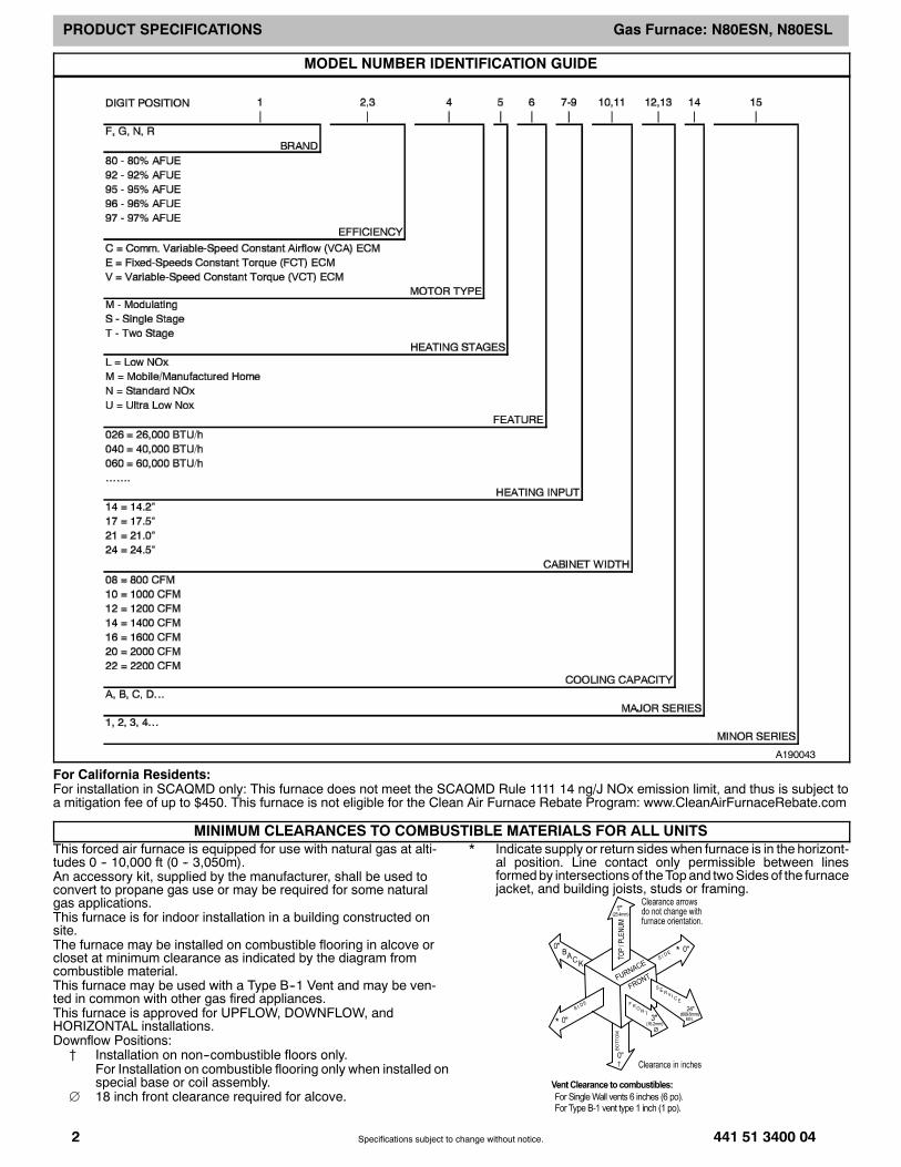
MODEL NUMBER IDENTIFICATION GUIDE
A190043
For California Residents:For installation in SCAQMD only: This furnace does not meet the SCAQMD Rule 1111 14 ng/J NOx emission limit, and thus is subject toa mitigation fee of up to $450. This furnace is not eligible for the Clean Air Furnace Rebate Program: www.CleanAirFurnaceRebate.com
MINIMUM CLEARANCES TO COMBUSTIBLE MATERIALS FOR ALL UNITSThis forced air furnace is equipped for use with natural gas at alti-tudes 0 -- 10,000 ft (0 -- 3,050m).An accessory kit, supplied by the manufacturer, shall be used toconvert to propane gas use or may be required for some naturalgas applications.This furnace is for indoor installation in a building constructed onsite.The furnace may be installed on combustible flooring in alcove orcloset at minimum clearance as indicated by the diagram fromcombustible material.This furnace may be used with a Type B--1 Vent and may be ven-ted in common with other gas fired appliances.This furnace is approved for UPFLOW, DOWNFLOW, andHORIZONTAL installations.Downflow Positions:{ Installation on non--combustible floors only.
For Installation on combustible flooring only when installed onspecial base or coil assembly.
18 inch front clearance required for alcove.
* Indicate supply or return sides when furnace is in the horizont-al position. Line contact only permissible between linesformedby intersections of theTopand twoSidesof the furnacejacket, and building joists, studs or framing.
PRODUCT SPECIFICATIONS Gas Furnace: N80ESN, N80ESL
441 51 3400 04 3Specifications subject to change without notice.
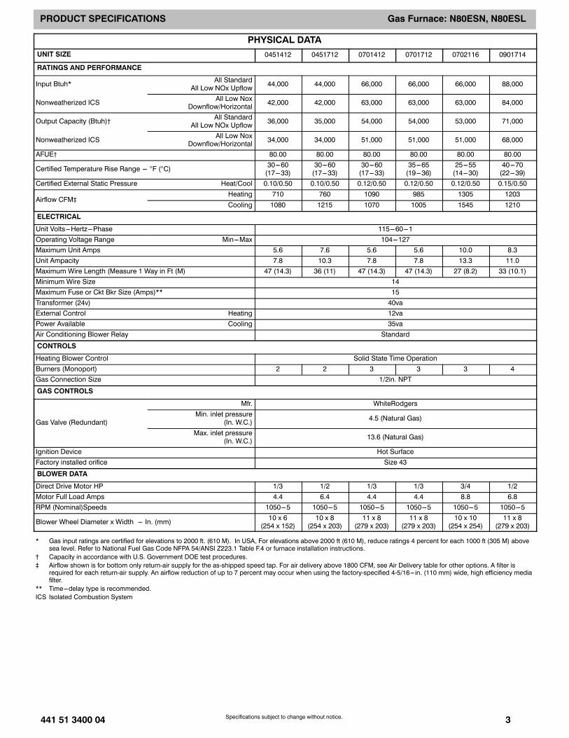
PHYSICAL DATAUNIT SIZE 0451412 0451712 0701412 0701712 0702116 0901714
RATINGS AND PERFORMANCE
Input Btuh* All StandardAll Low NOx Upflow 44,000 44,000 66,000 66,000 66,000 88,000
Nonweatherized ICS All Low NoxDownflow/Horizontal 42,000 42,000 63,000 63,000 63,000 84,000
Output Capacity (Btuh)† All StandardAll Low NOx Upflow 36,000 35,000 54,000 54,000 53,000 71,000
Nonweatherized ICS All Low NoxDownflow/Horizontal 34,000 34,000 51,000 51,000 51,000 68,000
AFUE† 80.00 80.00 80.00 80.00 80.00 80.00
Certified Temperature Rise Range --- F (C) 30---60(17---33)
30---60(17---33)
30---60(17---33)
35---65(19---36)
25---55(14---30)
40---70(22---39)
Certified External Static Pressure Heat/Cool 0.10/0.50 0.10/0.50 0.12/0.50 0.12/0.50 0.12/0.50 0.15/0.50
Airflow CFM‡Heating 710 760 1090 985 1305 1203Cooling 1080 1215 1070 1005 1545 1210
ELECTRICAL
Unit Volts---Hertz---Phase 115---60---1Operating Voltage Range Min---Max 104---127Maximum Unit Amps 5.6 7.6 5.6 5.6 10.0 8.3Unit Ampacity 7.8 10.3 7.8 7.8 13.3 11.0Maximum Wire Length (Measure 1 Way in Ft (M) 47 (14.3) 36 (11) 47 (14.3) 47 (14.3) 27 (8.2) 33 (10.1)Minimum Wire Size 14Maximum Fuse or Ckt Bkr Size (Amps)** 15Transformer (24v) 40vaExternal Control Heating 12vaPower Available Cooling 35vaAir Conditioning Blower Relay Standard
CONTROLS
Heating Blower Control Solid State Time OperationBurners (Monoport) 2 2 3 3 3 4Gas Connection Size 1/2in. NPT
GAS CONTROLS
Gas Valve (Redundant)
Mfr. WhiteRodgersMin. inlet pressure
(In. W.C.) 4.5 (Natural Gas)
Max. inlet pressure(In. W.C.) 13.6 (Natural Gas)
Ignition Device Hot SurfaceFactory installed orifice Size 43
BLOWER DATA
Direct Drive Motor HP 1/3 1/2 1/3 1/3 3/4 1/2Motor Full Load Amps 4.4 6.4 4.4 4.4 8.8 6.8RPM (Nominal)Speeds 1050---5 1050---5 1050---5 1050---5 1050---5 1050---5
Blower Wheel Diameter x Width --- In. (mm) 10 x 6(254 x 152)
10 x 8(254 x 203)
11 x 8(279 x 203)
11 x 8(279 x 203)
10 x 10(254 x 254)
11 x 8(279 x 203)
* Gas input ratings are certified for elevations to 2000 ft. (610 M). In USA, For elevations above 2000 ft (610 M), reduce ratings 4 percent for each 1000 ft (305 M) abovesea level. Refer to National Fuel Gas Code NFPA 54/ANSI Z223.1 Table F.4 or furnace installation instructions.
† Capacity in accordance with U.S. Government DOE test procedures.‡ Airflow shown is for bottom only return-air supply for the as-shipped speed tap. For air delivery above 1800 CFM, see Air Delivery table for other options. A filter is
required for each return-air supply. An airflow reduction of up to 7 percent may occur when using the factory-specified 4-5/16--- in. (110 mm) wide, high efficiency mediafilter.
** Time---delay type is recommended.ICS Isolated Combustion System
PRODUCT SPECIFICATIONS Gas Furnace: N80ESN, N80ESL
4 441 51 3400 04Specifications subject to change without notice.
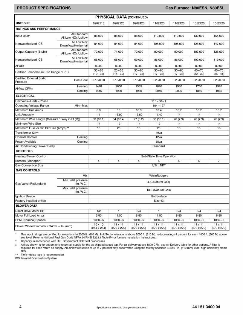
PHYSICAL DATA (CONTINUED)UNIT SIZE 0902116 0902120 0902420 1102120 1102420 1352420 1552420
RATINGS AND PERFORMANCE
Input Btuh* All StandardAll Low NOx Upflow 88,000 88,000 88,000 110,000 110,000 132,000 154,000
Nonweatherized ICS All Low NoxDownflow/Horizontal 84,000 84,000 84,000 105,000 105,000 126,000 147,000
Output Capacity (Btuh)† All StandardAll Low NOx Upflow 72,000 71,000 72,000 90,000 90,000 107,000 125,000
Nonweatherized ICS All Low NoxDownflow/Horizontal 68,000 68,000 69,000 85,000 86,000 102,000 119,000
AFUE† 80.00 80.00 80.00 80.00 80.00 80.00 80.00
Certified Temperature Rise Range F (C) 35---65(19---36)
25---55(14---30)
30---60(17---33)
30---60(17---33)
30---60(17---33)
40---70(22---39)
45---75(25---41)
Certified External StaticPressure Heat/Cool 0.15/0.50 0.15/0.50 0.15/0.50 0.20/0.50 0.20/0.80 0.20/0.50 0.20/0.50
Airflow CFM‡Heating 1418 1650 1565 1890 1930 1760 1995Cooling 1445 1980 1960 2040 2005 1810 1965
ELECTRICAL
Unit Volts---Hertz---Phase 115---60---1Operating Voltage Range Min---Max 104---127Maximum Unit Amps 8.3 13 10.3 13.4 10.7 10.7 10.7Unit Ampacity 11 16.90 13.50 17.40 14 14 14Maximum Wire Length (Measure 1 Way in Ft (M)) 33 (10.1) 34 (10.4) 27 (8.2) 33 (10.1) 26 (7.9) 26 (7.9) 26 (7.9)Minimum Wire Size 14 12 14 12 14 14 14Maximum Fuse or Ckt Bkr Size (Amps)** 15 20 15 20 15 15 15Transformer (24v) 40vaExternal Control Heating 12vaPower Available Cooling 35vaAir Conditioning Blower Relay Standard
CONTROLS
Heating Blower Control SolidState Time OperationBurners (Monoport) 4 4 4 5 5 6 7Gas Connection Size 1/2in. NPT
GAS CONTROLS
Gas Valve (Redundant)
Mfr. WhiteRodgersMin. inlet pressure
(In. W.C.) 4.5 (Natural Gas)
Max. inlet pressure(In. W.C.) 13.6 (Natural Gas)
Ignition Device Hot SurfaceFactory installed orifice Size 43
BLOWER DATA
Direct Drive Motor HP 1/2 1 3/4 1 3/4 3/4 3/4Motor Full Load Amps 6.80 11.50 8.80 11.50 8.80 8.80 8.80RPM (Nominal)Speeds 1050---5 1050---5 1050---5 1050---5 1050---5 1050---5 1050---5
Blower Wheel Diameter x Width --- In. (mm) 10 x 10(254 x 254)
11 x 11(279 x 279)
11 x 11(279 x 279)
11 x 11(279 x 279)
11 x 11(279 x 279)
11 x 11(279 x 279)
11 x 11(279 x 279)
* Gas input ratings are certified for elevations to 2000 ft. (610 M). In USA, for elevations above 2000 ft. (610 M), reduce ratings 4 percent for each 1000 ft. (305 M) abovesea level. Refer to National Fuel Gas Code NFPA 54/ANSI Z223.1 Table F.4 or furnace installation instructions.
† Capacity in accordance with U.S. Government DOE test procedures.‡ Airflow shown is for bottom only return-air supply for the as-shipped speed tap. For air delivery above 1800 CFM, see Air Delivery table for other options. A filter is
required for each return-air supply. An airflow reduction of up to 7 percent may occur when using the factory-specified 4-5/16--- in. (110 mm) wide, high efficiency mediafilter.
** Time---delay type is recommended.ICS Isolated Combustion System
PRODUCT SPECIFICATIONS Gas Furnace: N80ESN, N80ESL
441 51 3400 04 5Specifications subject to change without notice.
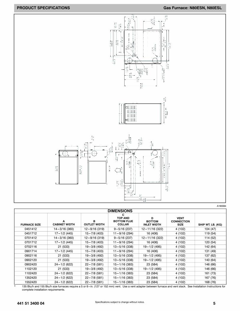
A190084
DIMENSIONS
FURNACE SIZEA
CABINET WIDTHB
OUTLET WIDTH
CTOP AND
BOTTOM FLUECOLLAR
DBOTTOM
INLET WIDTH
VENTCONNECTION
SIZE SHIP WT. LB. (KG)0451412 14---3/16 (360) 12---9/16 (319) 9---5/16 (237) 12---11/16 (322) 4 (102) 104 (47)0451712 17---1/2 (445) 15---7/8 (403) 11---9/16 (294) 16 (406) 4 (102) 119 (54)0701412 14---3/16 (360) 12---9/16 (319) 9---5/16 (237) 12---11/16 (322) 4 (102) 114 (52)0701712 17---1/2 (445) 15---7/8 (403) 11---9/16 (294) 16 (406) 4 (102) 120 (54)0702116 21 (533) 19---3/8 (492) 13---5/16 (338) 19---1/2 (495) 4 (102) 142 (64)0901714 17---1/2 (445) 15---7/8 (403) 11---9/16 (294) 16 (406) 4 (102) 131 (49)0902116 21 (533) 19---3/8 (492) 13---5/16 (338) 19---1/2 (495) 4 (102) 137 (62)0902120 21 (533) 19---3/8 (492) 13---5/16 (338) 19---1/2 (495) 4 (102) 140 (64)0902420 24---1/2 (622) 22---7/8 (581) 15---1/16 (383) 23 (584) 4 (102) 146 (66)1102120 21 (533) 19---3/8 (492) 13---5/16 (338) 19---1/2 (495) 4 (102) 146 (66)1102420 24---1/2 (622) 22---7/8 (581) 15---1/16 (383) 23 (584) 4 (102) 161 (73)1352420 24---1/2 (622) 22---7/8 (581) 15---1/16 (383) 23 (584) 4 (102) 167 (76)1552420 24---1/2 (622) 22---7/8 (581) 15---1/16 (383) 23 (584) 4 (102) 168 (76)
* 135 Btu/h and 155 Btu/h size furnaces require a 5 or 6--- in. (127 or 152 mm) vent. Use a vent adapter between furnace and vent stack. See Installation Instructions forcomplete installation requirements.
PRODUCT SPECIFICATIONS Gas Furnace: N80ESN, N80ESL
6 441 51 3400 04Specifications subject to change without notice.
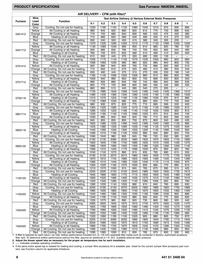
AIR DELIVERY -- CFM (with filter)*
FurnaceWireLeadColor
FunctionTest Airflow Delivery @ Various External Static Pressures
0.1 0.2 0.3 0.4 0.5 0.6 0.7 0.8 0.9 1
0451412
Gray Cooling. Do not use for heating. 1230 1190 1155 1120 1080 1045 1010 975 935 895Yellow Alt Cooling or alt Heating 980 945 920 890 855 815 770 735 690 645Orange Alt Cooling or alt Heating 770 720 685 640 600 560 520 475 430 385Blue Heating or alt Cooling 710 660 620 580 540 490 455 415 375 335Red Alt Cooling. Do not use for heating. 600 540 500 455 415 385 345 305 235 ---
0451712
Gray Cooling. Do not use for heating. 1370 1335 1295 1255 1215 1175 1135 1095 1055 1020Yellow Alt Cooling or alt Heating 1130 1085 1040 995 955 910 865 825 780 730Orange Alt Cooling or alt Heating 930 885 835 795 745 700 655 600 545 495Blue Heating or alt Cooling 760 720 670 625 580 515 460 410 355 300Red Alt Cooling. Do not use for heating. 610 500 445 375 320 260 200 135 --- ---
0701412
Gray Cooling. Do not use for heating. 1205 1170 1143 1105 1070 1035 1000 960 925 885Blue Heating or alt Cooling 1095 1060 1030 995 960 925 885 840 800 735Yellow Alt Cooling or alt Heating 920 880 845 805 765 730 685 620 560 510Orange Alt Cooling. Do not use for heating. 715 650 610 575 520 465 410 380 305 245Red Alt Cooling. Do not use for heating. 635 490 445 375 315 270 205 230 190 140
0701712
Gray Cooling. Do not use for heating. 1185 1140 1095 1055 1005 960 915 865 820 780Yellow Alt Cooling or alt Heating 1000 940 895 850 800 750 695 650 600 555Blue Heating or alt Cooling 990 935 895 845 790 740 690 640 590 535Orange Alt Cooling or alt Heating 855 775 720 660 605 560 495 435 385 335Red Alt Cooling. Do not use for heating. 860 685 515 445 385 340 275 205 --- ---
0702116
Gray Cooling. Do not use for heating. 1735 1685 1640 1595 1545 1495 1450 1405 1360 1310Yellow Alt Cooling or alt Heating 1480 1435 1395 1340 1290 1240 1190 1135 1085 1030Blue Heating or alt Cooling 1315 1275 1225 1180 1135 1085 1030 975 915 860Orange Alt Cooling or alt Heating 1135 1080 1030 985 935 885 835 770 705 645Red Alt Cooling. Do not use for heating. 980 930 875 820 775 715 665 595 530 455
0901714
Gray Cooling. Do not use for heating. 1355 1320 1285 1245 1210 1165 1125 1080 1025 815Yellow Alt Cooling or alt Heating 1295 1255 1220 1185 1140 1100 1055 1005 955 815Blue Heating or alt Cooling 1220 1185 1150 1105 1065 1025 975 915 840 740Orange Alt Cooling or alt Heating 1030 985 940 900 845 790 715 655 590 535Red Alt Cooling. Do not use for heating. 945 905 855 800 750 670 600 540 490 435
0902116
Gray Cooling. Do not use for heating. 1625 1580 1535 1490 1445 1395 1340 1260 1135 995Yellow Alt Cooling or alt Heating 1425 1380 1335 1290 1235 1185 1125 1075 1020 640Blue Heating or alt Cooling 1440 1395 1350 1305 1255 1200 1145 1090 1040 950Orange Alt Cooling or alt Heating 1260 1210 1160 1105 1050 990 935 880 820 755Red Alt Cooling. Do not use for heating. 1095 1040 980 905 845 780 720 650 585 520
0902120
Gray Cooling. Do not use for heating. 2180 2130 2080 2030 1980 1925 1870 1805 1745 1680Yellow Alt Cooling or alt Heating 1900 1845 1795 1740 1685 1635 1570 1500 1435 1375Blue Heating or alt Cooling 1685 1620 1565 1505 1455 1385 1320 1260 1200 1140Orange Alt Cooling or alt Heating 1390 1315 1240 1175 1095 1030 970 900 825 760Red Alt Cooling. Do not use for heating. 1240 1155 1075 990 915 835 765 690 615 555
0902420
Gray Cooling. Do not use for heating. 2190 2135 2075 2015 1960 1900 1835 1775 1705 1630Yellow Alt Cooling or alt Heating 1870 1810 1745 1685 1625 1565 1495 1420 1345 1280Blue Heating or alt Cooling 1580 1510 1445 1385 1320 1240 1175 1115 1050 970Orange Alt Cooling or alt Heating 1305 1220 1160 1075 1000 930 865 770 690 610Red Alt Cooling. Do not use for heating. 1210 1075 1000 915 845 765 675 595 515 425
1102120
Gray Cooling. Do not use for heating. 2255 2205 2150 2100 2040 1985 1920 1835 1735 1615Blue Heating or alt Cooling 1945 1890 1830 1770 1715 1655 1600 1545 1480 1430Yellow Alt Cooling or alt Heating 1600 1525 1465 1400 1335 1275 1210 1150 1080 1015Orange Alt Cooling. Do not use for heating. 1420 1340 1280 1200 1140 1065 1005 925 865 790Red Alt Cooling. Do not use for heating. 1280 1205 1140 1055 990 910 840 760 695 630
1102420
Gray Cooling. Do not use for heating. 2250 2190 2130 2070 2005 1950 1885 1820 1755 1685Blue Heating or alt Cooling 1995 1930 1865 1800 1740 1670 1605 1535 1465 1400Yellow Alt Cooling. Do not use for heating. 1540 1460 1385 1305 1235 1165 1095 1035 955 890Orange Alt Cooling or alt Heating 1345 1195 1135 1055 980 920 845 770 695 620Red Alt Cooling. Do not use for heating. 1335 1075 965 890 820 735 660 580 505 440
1352420
Gray Cooling. Do not use for heating. 2065 2005 1940 1875 1810 1740 1670 1600 1530 1470Blue Heating or alt Cooling 1825 1760 1695 1630 1560 1490 1420 1350 1275 1205Yellow Alt Cooling or alt Heating 1760 1690 1625 1555 1485 1415 1345 1275 1200 1130Orange Alt Cooling. Do not use for heating. 1620 1550 1480 1405 1335 1260 1195 1130 1065 995Red Alt Cooling. Do not use for heating. 1325 1260 1185 1100 1025 955 885 805 735 670
1552420
Gray Cooling. Do not use for heating. 2205 2150 2090 2030 1965 1905 1840 1780 1710 1645Blue Heating or alt Cooling 2055 1995 1935 1875 1810 1750 1690 1615 1540 1460Yellow Alt Cooling or alt Heating 1860 1795 1730 1670 1605 1540 1470 1395 1320 1250Orange Alt Cooling. Do not use for heating. 1495 1430 1355 1285 1210 1130 1065 995 930 850Red Alt Cooling. Do not use for heating. 1295 1085 1000 910 835 765 670 600 530 465
1. A filter is required for each return---air inlet. Airflow performance included 3/4--- in. (19 mm) washable filter media such as contained in factory---authorized accessoryfilter rack. To determine airflow performance without this filter, assume an additional 0.1 In. W.C. available external static pressure.
2. Adjust the blower speed tabs as necessary for the proper air temperature rise for each installation.3. --- --- Indicates unstable operating conditions.4. If the same motor speed tap is needed for heating and cooling, a Jumper Wire accessory kit is available (see sheet for the current Jumper Wire accessory part num-ber), see Function column for applicable limitations.
PRODUCT SPECIFICATIONS Gas Furnace: N80ESN, N80ESL
441 51 3400 04 7Specifications subject to change without notice.
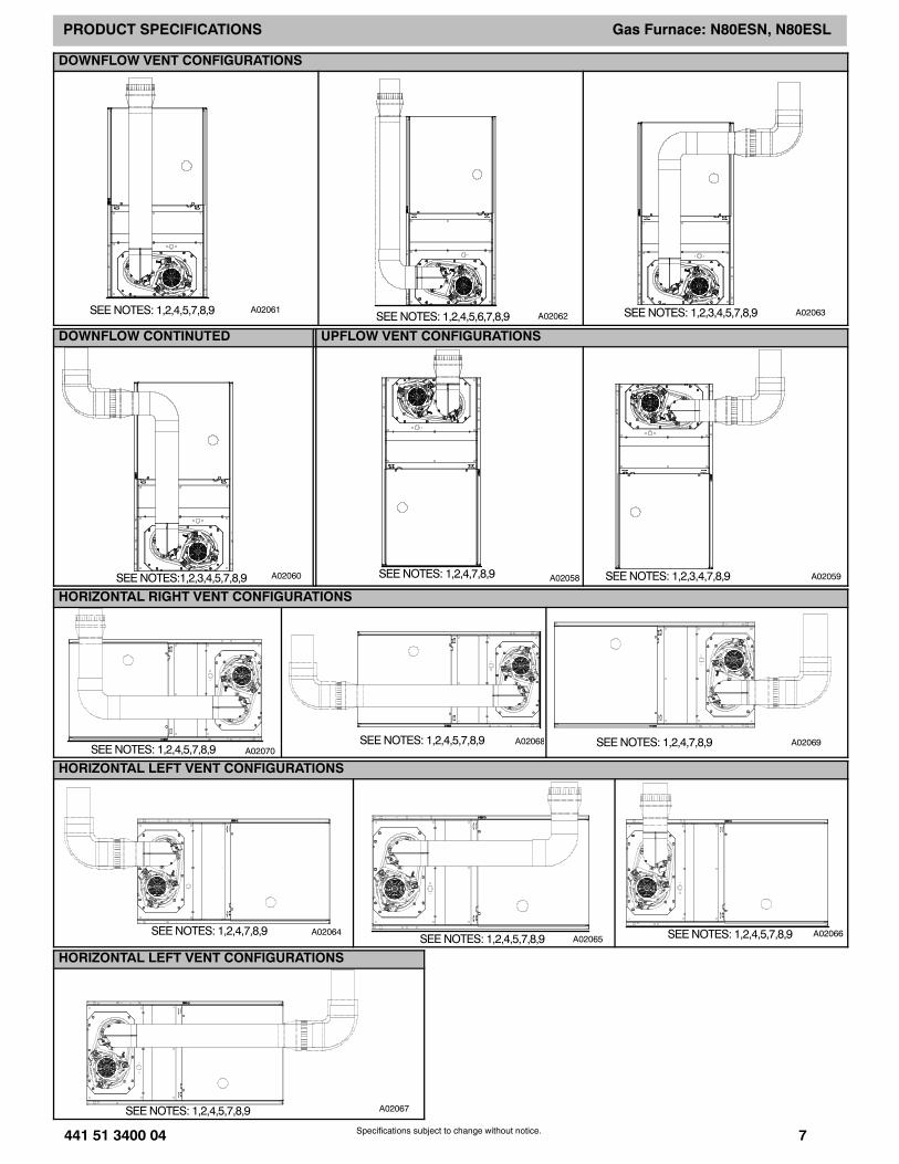
DOWNFLOW VENT CONFIGURATIONS
SEENOTES: 1,2,4,5,7,8,9 A02061SEENOTES: 1,2,4,5,6,7,8,9 A02062 SEENOTES: 1,2,3,4,5,7,8,9 A02063
DOWNFLOW CONTINUTED UPFLOW VENT CONFIGURATIONS
SEENOTES:1,2,3,4,5,7,8,9 A02060 A02058SEENOTES: 1,2,4,7,8,9 SEENOTES: 1,2,3,4,7,8,9 A02059
HORIZONTAL RIGHT VENT CONFIGURATIONS
SEENOTES: 1,2,4,5,7,8,9 A02070SEENOTES: 1,2,4,5,7,8,9 A02068 SEENOTES: 1,2,4,7,8,9 A02069
HORIZONTAL LEFT VENT CONFIGURATIONS
SEENOTES: 1,2,4,7,8,9 A02064SEENOTES: 1,2,4,5,7,8,9 A02065 SEENOTES: 1,2,4,5,7,8,9 A02066
HORIZONTAL LEFT VENT CONFIGURATIONS
SEENOTES: 1,2,4,5,7,8,9 A02067
PRODUCT SPECIFICATIONS Gas Furnace: N80ESN, N80ESL
8 441 51 3400 04Specifications subject to change without notice.
Venting Notes1. For common vent, vent connector sizing and vent material, use the NFGC.2. Immediately increase to 5 inch (127 mm) or 6 inch (152 mm) vent connector outside furnace casing when 5 inch (127 mm) vent
connector is required, refer to Note 1 above.3. Side outlet vent for upflow and downflow installations must use Type B vent immediately after exiting the furnace, except when
the Downflow Vent Guard Kit, is used in the downflow position4. Type--B vent where required, refer to the Note 1 above.5. A 4 inch (102 mm) single--wall (26 ga. minimum) vent must be used inside furnace casing and when the Downflow Vent Guard Kit
is used external to the furnace.6. Accessory Downflow Vent Guard Kit is required in downflow installations with lower vent configuration.7. Chimney Adapter Kit may be required for exterior masonry chimney applications. Refer to Chimney Adapter Kit for sizing and
complete application details.8. Secure vent connector to furnace elbow with (2) corrosion--resistant sheet metal screws, spaced approximately 180 apart.9. Secure all other single wall vent connector joints with (3) corrosion resistant screws spaced approximately 120 apart. Secure
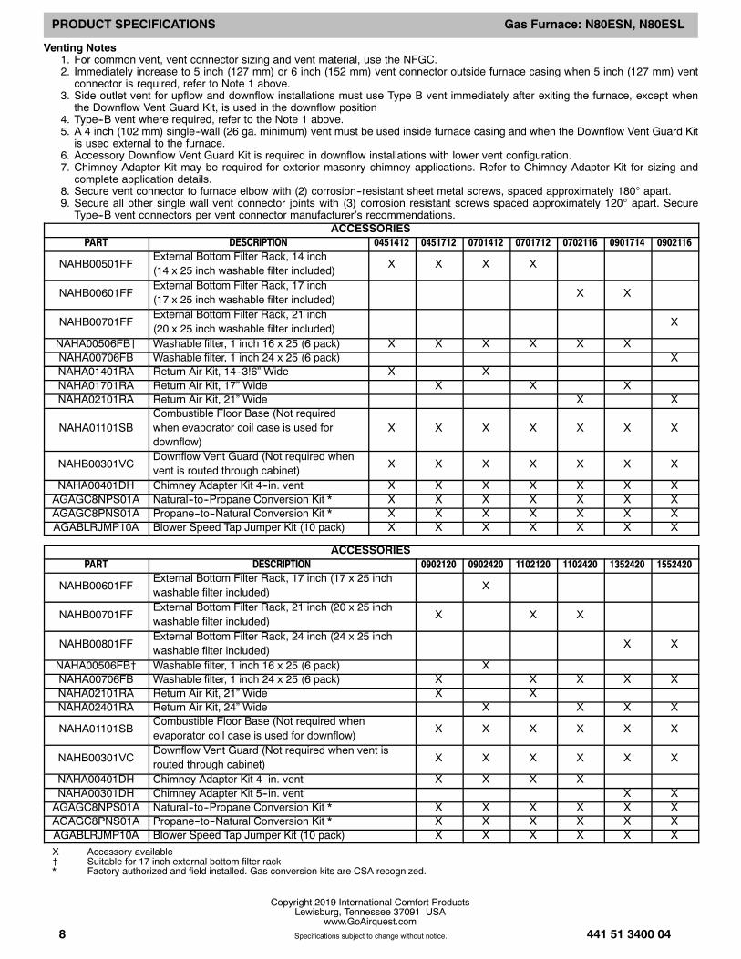
Type--B vent connectors per vent connector manufacturer’s recommendations.ACCESSORIES
PART DESCRIPTION 0451412 0451712 0701412 0701712 0702116 0901714 0902116
NAHB00501FFExternal Bottom Filter Rack, 14 inch(14 x 25 inch washable filter included)
X X X X
NAHB00601FFExternal Bottom Filter Rack, 17 inch(17 x 25 inch washable filter included)
X X
NAHB00701FFExternal Bottom Filter Rack, 21 inch(20 x 25 inch washable filter included)
X
NAHA00506FB† Washable filter, 1 inch 16 x 25 (6 pack) X X X X X XNAHA00706FB Washable filter, 1 inch 24 x 25 (6 pack) XNAHA01401RA Return Air Kit, 14--3!6” Wide X XNAHA01701RA Return Air Kit, 17” Wide X X XNAHA02101RA Return Air Kit, 21” Wide X X
NAHA01101SBCombustible Floor Base (Not requiredwhen evaporator coil case is used fordownflow)
X X X X X X X
NAHB00301VCDownflow Vent Guard (Not required whenvent is routed through cabinet)
X X X X X X X
NAHA00401DH Chimney Adapter Kit 4--in. vent X X X X X X XAGAGC8NPS01A Natural--to--Propane Conversion Kit * X X X X X X XAGAGC8PNS01A Propane--to--Natural Conversion Kit * X X X X X X XAGABLRJMP10A Blower Speed Tap Jumper Kit (10 pack) X X X X X X X
ACCESSORIESPART DESCRIPTION 0902120 0902420 1102120 1102420 1352420 1552420
NAHB00601FFExternal Bottom Filter Rack, 17 inch (17 x 25 inchwashable filter included)
X
NAHB00701FFExternal Bottom Filter Rack, 21 inch (20 x 25 inchwashable filter included)
X X X
NAHB00801FFExternal Bottom Filter Rack, 24 inch (24 x 25 inchwashable filter included)
X X
NAHA00506FB† Washable filter, 1 inch 16 x 25 (6 pack) XNAHA00706FB Washable filter, 1 inch 24 x 25 (6 pack) X X X X XNAHA02101RA Return Air Kit, 21” Wide X XNAHA02401RA Return Air Kit, 24” Wide X X X X
NAHA01101SBCombustible Floor Base (Not required whenevaporator coil case is used for downflow)
X X X X X X
NAHB00301VCDownflow Vent Guard (Not required when vent isrouted through cabinet)
X X X X X X
NAHA00401DH Chimney Adapter Kit 4--in. vent X X X XNAHA00301DH Chimney Adapter Kit 5--in. vent X XAGAGC8NPS01A Natural--to--Propane Conversion Kit * X X X X X XAGAGC8PNS01A Propane--to--Natural Conversion Kit * X X X X X XAGABLRJMP10A Blower Speed Tap Jumper Kit (10 pack) X X X X X X
X Accessory available† Suitable for 17 inch external bottom filter rack* Factory authorized and field installed. Gas conversion kits are CSA recognized.
Copyright 2019 International Comfort ProductsLewisburg, Tennessee 37091 USA
www.GoAirquest.com