Embed Size (px)
Citation preview
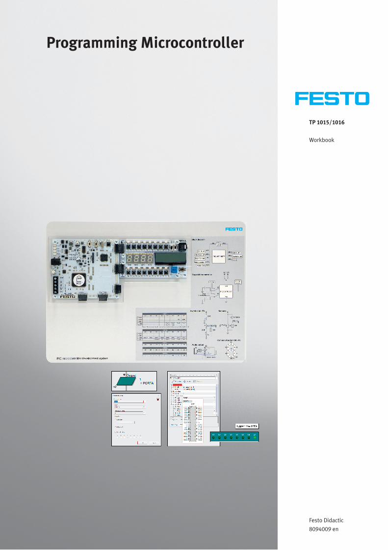
TP 1015/1016
Workbook
Festo Didactic
8094009 en
Programming Microcontroller

Order no. 8094009
Edition: 06/2018
Author: Matrix Technology Solution Limited
Layout: Frank Ebel
© Festo Didactic SE, Rechbergstraße 3, 73770 Denkendorf, Germany, 2018
All rights reserved.
+49 711 3467-0 www.festo-didactic.com
+49 711 34754-88500 [email protected]
The purchaser shall receive a single right of use which is non-exclusive, non-time-limited and limited
geographically to use at the purchaser's site/location as follows.
The purchaser shall be entitled to use the work to train his/her staff at the purchaser's site/location and
shall also be entitled to use parts of the copyright material as the basis for the production of his/her
own training documentation for the training of his/her staff at the purchaser's site/location with
acknowledgement of source and to make copies for this purpose. In the case of schools/technical
colleges and training centres, the right of use shall also include use by school and college students and
trainees at the purchaser's site/location for teaching purposes.
The right of use shall in all cases exclude the right to publish the copyright material or to make this
available for use on intranet, Internet and LMS platforms and databases such as Moodle, which allow
access by a wide variety of users, including those outside of the purchaser's site/location.
Entitlement to other rights relating to reproductions, copies, adaptations, translations, microfilming and
transfer to and storage and processing in electronic systems, no matter whether in whole or in part,
shall require the prior consent of Festo Didactic.
© Festo Didactic 8094009 III
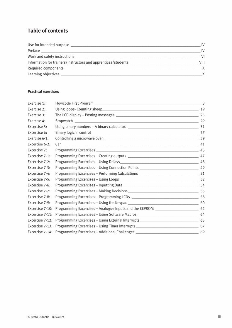
Table of contents
Use for intended purpose __________________________________________________________________ IV
Preface _________________________________________________________________________________ IV
Work and safety instructions ________________________________________________________________ VI
Information for trainers/instructors and apprentices/students ___________________________________ VIII
Required components _____________________________________________________________________ IX
Learning objectives ________________________________________________________________________X
Practical exercises
Exercise 1: Flowcode First Program _______________________________________________________ 3
Exercise 2: Using loops- Counting sheep _________________________________________________ 19
Exercise 3: The LCD display – Posting messages __________________________________________ 25
Exercise 4: Stopwatch _______________________________________________________________ 29
Excercise 5: Using binary numbers – A binary calculator. ____________________________________ 31
Excercise 6: Binary logic in control ______________________________________________________ 37
Exercise 6-1: Controlling a microwave oven ________________________________________________ 39
Excercise 6-2: Car ______________________________________________________________________ 41
Excercise 7: Programming Excercises ____________________________________________________ 45
Excercise 7-1: Programming Excercises – Creating outputs ____________________________________ 47
Excercise 7-2: Programming Excercises – Using Delays________________________________________ 48
Excercise 7-3: Programming Excercises – Using Connection Points ______________________________ 49
Excercise 7-4: Programming Excercises – Performing Calculations ______________________________ 51
Excercise 7-5: Programming Excercises – Using Loops ________________________________________ 52
Excercise 7-6: Programming Excercises – Inputting Data ______________________________________ 54
Excercise 7-7: Programming Excercises – Making Decisions ____________________________________ 55
Excercise 7-8: Programming Excercises – Programming LCDs __________________________________ 58
Excercise 7-9: Programming Excercises – Using the Keypad ____________________________________ 60
Excercise 7-10: Programming Excercises – Analogue Inputs and the EEPROM ______________________ 62
Excercise 7-11: Programming Excercises – Using Software Macros _______________________________ 64
Excercise 7-12: Programming Excercises – Using External Interrupts ______________________________ 65
Excercise 7-13: Programming Excercises – Using Timer Interrupts ________________________________ 67
Excercise 7-14: Programming Excercises – Additional Challenges ________________________________ 69

IV Name: __________________________________ Date: ____________ © Festo Didactic 8094009
Use for intended purpose
The products included in the learning system for microcontroller systems may only be used:
For their intended use in teaching and training applications
When their safety functions are in perfect condition
The products included in Festo Didactic’s learning system for microcontroller systems are designed in
accordance with the latest technology and recognized safety rules.
The learning system from Festo Didactic has been developed and produced exclusively for basic and further
training in the field of microcontroller systems. The training company and/or trainers must ensure that all
apprentices observe the safety precautions described in this workbook.
Festo Didactic hereby excludes any and all liability for damages suffered by apprentices, the training
company and/or any third parties, which occur during use of the equipment sets in situations that serve any
purpose other than training and/or vocational education, unless such damages have been caused by Festo
Didactic due to malicious intent or gross negligence.
Preface
Festo Didactic’s learning system for microcontroller systems is geared towards various educational
backgrounds and vocational requirements.
The training system is continuously updated and expanded in accordance with developments in the field of
education, as well as actual professional practice.
These learning solutions encompass a wide range of topics which are directly related to microcontrollers
and the integration and study of additional components and topics including inpuit/output devices, use of
sensors, actuators and motors, relays and more. Instructors can easily expand the scope of learning by
selecting other components available.
All of the systems are modular, thus permitting expansion and flexibility.
Hardware
The hardware included is comprised of rugged, industrial components and systems that are specially
designed for training purposes. The components are specifically designed and matched to the projects in
the accompanying media.

© Festo Didactic 8094009 Name: __________________________________ Date: ____________ V
Media
The media provided for the individual topics consist of a mixture of courseware and software. The practically
oriented courseware includes a workbook (practical exercises with supplementary instructions and sample
solutions). Software is also available and required for complete completion of the provided workbook
(although is non-essential, as users can use a traditional C compiler, for which no workbook is provided).
Flowcode 8 software for 8-bit PIC, or Arduino microcontrollers
The workbook is available in English. Software is available in several languages. They are intended for use in
classroom instruction, but are also suitable for self-study.
Software license types
We offer the following three license types for Flowcode:
Single user licence
For individuals, purhasing single or small units. This is available for 8-bit PIC, Arduino or both categories
of hardware.
10 user licence
For small centres purchasing up to 10 units of hardware. This is available for 8-bit PIC, Arduino or both
categories of hardware.
Site licence
For larger centres purchasing 10+ units of hardware, or where there is benefit in more than 10
workstations having access to Flowcode (e.g. for simulation purposes). This is available for 8-bit PIC,
Arduino or both categories of hardware.
Note
The full rights of use are in compliance with the stipulations included in the legal notice of the
purchased workbook.
Do you have tips or suggestions for improving this workbook?
If so, please inform us by e-mail at [email protected].
The authors and Festo Didactic look forward to your comments.
VI Name: __________________________________ Date: ____________ © Festo Didactic 8094009
Work and safety instructions
General
Apprentices should only work with the circuits under the supervision of an instructor.
Observe the specifications included in the data sheets and operating instructions for the individual
components and, in particular, all safety instructions!
Faults which may impair safety should not be generated.
Wear personal safety equipment (safety glasses, hearing protection, safety shoes) when working on
circuits.
Provide the trainer/instructor with confirmation that you have read and understood the safety
instructions and warnings by affixing your signature. You are only authorized to participate in the
laboratory event after appending your signature.
Mechanical safety
Switch off the power supply.
– Switch off working and control power before working on the circuit.
– Only reach into the setup when it’s at a complete standstill.
– Be aware of potential overtravel times for the drives.
Mount all of the components securely on the profile plate.
Make sure that limit valves are not actuated from the front.
Risk of injury during troubleshooting.
Use a tool such as a screwdriver to actuate limit switches.
Set all components up so that it’s easy to activate the switches and interrupters.
Follow the instructions about positioning the components.
Electrical safety
Disconnect from all sources of electrical power.
– Switch off the power supply before working on the circuit.
– Please note that electrical energy may be stored in individual components. Further information on
this issue is available in the data sheets and operating instructions included with the components.
Use protective extra-low voltage only: max. 24 V dc.
Establishing and disconnecting electrical connections
– Electrical connections may only be established in the absence of voltage.
– Electrical connections may only be disconnected in the absence of voltage.
Use only connecting cables with safety plugs for electrical connections.

Work and Safety Instructions
© Festo Didactic 8094009 Name: __________________________________ Date: ____________ VII
When laying connecting cables, make sure they’re not kinked or pinched.
Do not lay cables over hot surfaces.
– Hot surfaces are identified with a corresponding warning symbol.
Make sure that connecting cables are not subjected to continuous tensile loads.
Devices with an earth terminal must always be grounded.
– If a ground connection (green-yellow laboratory socket) is available, it must always be connected to
protective earth. Protective earth must always be connected first (before voltage), and must always
be disconnected last (after voltage).
– Some devices have high leakage current. These devices must be additionally grounded with a
protective earth conductor.
The device is not equipped with an integrated fuse unless specified otherwise in the technical data.
Always pull on the plug when disconnecting connecting cables – never pull the cable.
VIII Name: __________________________________ Date: ____________ © Festo Didactic 8094009
Information for trainers/instructors and apprentices/students
Workbook
This workbook is broken down into practical exercises, including numerous programming exercises.
Solutions section
Solutions in text passages appear in red.
Solutions and supplements in graphics or diagrams have a red or gray background.
Additional information for the trainer is identified as “Information for the trainer/instructor”. This
information is not included in the worksheets.
Structure of the training content
All exercises are structured individually with the following layout:
Description of the problem
Work aids
Hardware layout
Exercise instructions
Prerequisites
Basic knowledge in the following areas is required in order to process the exercises in this workbook:
Microcontroller or microprocessors including PIC & Arduino
Understanding of a graphical programming paradigm

© Festo Didactic 8094009 Name: __________________________________ Date: ____________ IX
Required components
The components and software required for processing all of the work assignments are listed below:
Component Description / Order no. Quantity
Windows PC running version Windows 7 or later 1
Flowcode 8 Academic license 1
TP1015 Festo PIC microcontroller development system
or
TP1016 Festo Arduino development system
8085562
8085563
1
1
Component Order no. Quantity
Festo Grove sensor board 8083414 1
Festo Keypad board 8083408 1
Festo Relay board 8083419 1
Festo Prototype/Patch board 8083406 1
Festo Actuators training board 8083413 1

X Name: __________________________________ Date: ____________ © Festo Didactic 8094009
Learning objectives
After completion of the exercises in this workbook, the student should understand the basic of programming
micro controller
Addressing I/O
Stucture loops (while, )
Decision making ( If, case)
Compiling and downloading
Variable types
Instruction, calculation,
Communicating with devices
© Festo Didactic 8094009 Name: __________________________________ Date: ____________ 1
Practical exercises
Exercise 1: Flowcode First Program _______________________________________________________ 3
Exercise 2: Using loops- Counting sheep _________________________________________________ 19
Exercise 3: The LCD display – Posting messages __________________________________________ 25
Exercise 4: Stopwatch _______________________________________________________________ 29
Excercise 5: Using binary numbers – A binary calculator. ____________________________________ 31
Excercise 6: Binary logic in control ______________________________________________________ 37
Exercise 6-1: Controlling a microwave oven ________________________________________________ 39
Excercise 6-2: Car ______________________________________________________________________ 41
Excercise 7: Programming Excercises ____________________________________________________ 45
Excercise 7-1: Programming Excercises – Creating outputs ____________________________________ 47
Excercise 7-2: Programming Excercises – Using Delays________________________________________ 48
Excercise 7-3: Programming Excercises – Using Connection Points ______________________________ 49
Excercise 7-4: Programming Excercises – Performing Calculations ______________________________ 51
Excercise 7-5: Programming Excercises – Using Loops ________________________________________ 52
Excercise 7-6: Programming Excercises – Inputting Data ______________________________________ 54
Excercise 7-7: Programming Excercises – Making Decisions ____________________________________ 55
Excercise 7-8: rogramming Excercises – Programming LCDs ____________________________________ 58
Excercise 7-9: Programming Excercises – Using the Keypad ____________________________________ 60
Excercise 7-10: Programming Excercises – Analogue Inputs and the EEPROM ______________________ 62
Excercise 7-11: Programming Excercises – Using Software Macros _______________________________ 64
Excercise 7-12: Programming Excercises – Using External Interrupts ______________________________ 65
Excercise 7-13: Programming Excercises – Using Timer Interrupts ________________________________ 67
Excercise 7-14: Programming Excercises – Additional Challenges ________________________________ 69

2 Name: __________________________________ Date: ____________ © Festo Didactic 8094009

© Festo Didactic 8094009 Name: __________________________________ Date: ____________ 3
Exercise 1: Flowcode First Program
1. Commissioning the system
Information
Create a program that lights an LED attached to the microcontroller.
This program introduces the topic of how to control a digital output.
The tutorial provides a clear, step by step approach enabling you to create your first program using
Flowcode. It can be run in Flowcode’s simulation mode before compiling to the board for testing
and development.
Note: This tutorial refers to the port settings (ports A and B) as used with PIC. For Arduino users,
please use ports C and D as appropriate. (Port C on the Arduino ’Maps’ to Port A of the Combo
board).
Start a new project
Select 'New' Project’ in the box or Goto >
File > New and choose a target
microcontroller from the list that appears.

Exercise 1: Flowcode First Program
4 Name: __________________________________ Date: ____________ © Festo Didactic 8094009
For TP1015, select 16F18877.
For TP1016, select Arduino Uno R3 PDIP
Setting up the project can be done in a
variety of ways. Here the 16F18877 chip
has been selected via the PIC image.
Instead of selecting the 16F18877 chip, the
boards can be selected directly. Here the
BL0011 board has been selected via the
FREE image.
Here the Arduino board has been selected via
the FREE image.
TIP
This can be changed later if you get it wrong.
Goto > Build > Project Options > Choose a Target
and select a target microcontroller from the list
that appears as before.
Exercise 1: Flowcode First Program
© Festo Didactic 8094009 Name: __________________________________ Date: ____________ 5
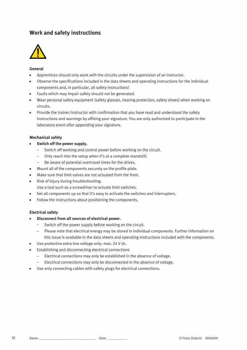
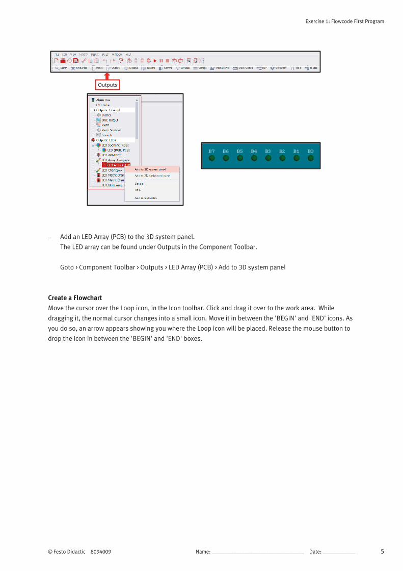
Outputs
– Add an LED Array (PCB) to the 3D system panel.
The LED array can be found under Outputs in the Component Toolbar.
Goto > Component Toolbar > Outputs > LED Array (PCB) > Add to 3D system panel
Create a Flowchart
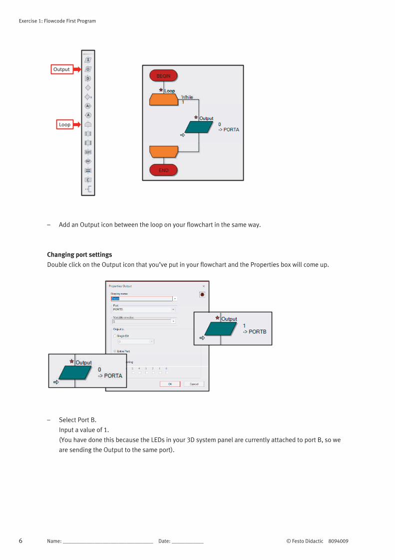
Move the cursor over the Loop icon, in the Icon toolbar. Click and drag it over to the work area. While
dragging it, the normal cursor changes into a small icon. Move it in between the 'BEGIN' and 'END' icons. As
you do so, an arrow appears showing you where the Loop icon will be placed. Release the mouse button to
drop the icon in between the 'BEGIN' and 'END' boxes.
Exercise 1: Flowcode First Program
6 Name: __________________________________ Date: ____________ © Festo Didactic 8094009
Output
Loop
– Add an Output icon between the loop on your flowchart in the same way.
Changing port settings
Double click on the Output icon that you’ve put in your flowchart and the Properties box will come up.
– Select Port B.
Input a value of 1.
(You have done this because the LEDs in your 3D system panel are currently attached to port B, so we
are sending the Output to the same port).

Exercise 1: Flowcode First Program
© Festo Didactic 8094009 Name: __________________________________ Date: ____________ 7
Run the simulation
Select the Run icon from the menu bar and the simulation of the LED will light up in the 3D system panel.
Run (F5)
Stop (Shift+F5)
Simulation mode
TIP
Remember to stop your simulation before doing anything else.
(If Flowcode isn’t doing as you expect, check that you haven’t accidentally left your simulation
running).
Save your program and then Compile to chip to test on the board. You should see the first LED light up.
Select the Compile to chip image from the menu as shown, or Goto > Build > Compile to chip
Save (Control+S)
Compile to chip
Lower row LEDs

Exercise 1: Flowcode First Program
8 Name: __________________________________ Date: ____________ © Festo Didactic 8094009
Changes to try after successfully lighting your LED
Highlight the image of the LED array in the 3D system panel and right click to select the Properties.
Here you can change the number of LEDs in your array by changing the value under count.
Try changing the colour of the LEDs in the simulation as shown below.
Property settings for 6 red LEDS. 6 red LEDS in simulation.
Changing the port settings.
Bring up the Output icon properties (double click) and change the Port settings to Port A.
Highlight the image of the LED array in the 3D system panel and right click to select the Properties, and
change the Port settings to Port A.
Select the Compile to chip image from the menu as shown, or Goto > Build > Compile to chip
Upper row LEDs
Run in simulation mode and then compile to chip. You should see the first LED of the other row light up.

Exercise 1: Flowcode First Program
© Festo Didactic 8094009 Name: __________________________________ Date: ____________ 9
You can practise changing the ports by changing them back to port B.
Change the value from 1 to 255. Test in simulation mode and then compile to chip (all 8 LEDs light up).
Experiment using other values.
TIP
See Number Systems Worksheet.

Exercise 1: Flowcode First Program
10 Name: __________________________________ Date: ____________ © Festo Didactic 8094009
Binary Numbers
Digital electronic devices can't cope with decimal
numbers. Instead, they use the binary system,
which uses only two numbers 0 and 1. The number 1
could be represented by a high voltage signal, while
number 0 could be a low voltage.
The decimal system uses ten numbers, 0, 1, 2, 3, 4,
5, 6, 7, 8 and 9. On reaching the last of these, 9, we
start again with 0, but add another number in front.
For example, after 8 and 9 comes 10, and after 18
and 19 comes 20 and so on. When we reach 99,
both of these go back to 0s but with a 1 in front, to
make 100.
Decimal Same in
binary
0 0
1 1
2 10
3 11
4 100
5 101
6 110
7 111
8 1000
9 1001
10 1010
Binary Value
16 8 4 2 1
In binary, the same thing happens, but a lot more often, because it uses only 0s and
1s. Counting up starts with 0, then 1, then back to 0 with a 1 in front, making 10 (not
ten - it's two) Next comes 11 (three) and start again with two 0s but with a 1 in front,
to give 100 (four) and so on.
Notice that each time the binary 1 moves one place to the left, it doubles in value of
the number in decimal.
We can use this idea to convert between number systems.
TIP
In any binary number, the bit at the left-hand end, the Most Significant Bit (MSB), has the highest
value. The one at the right-hand end, the Least Significant Bit (LSB), is worth least.
Decimal Same in
binary
1 1
2 10
4 100
8 1000

Exercise 1: Flowcode First Program
© Festo Didactic 8094009 Name: __________________________________ Date: ____________ 11
Hex Numbers
Hexadecimal, 'hex' for short, is a another system for representing numbers.
A binary digit is either 0 or 1.
A decimal digit varies between 0 and 10.
A hex digit has sixteen possible states.
Sixteen states is a problem, as we have only the digits from 0 to 9. To get round this, we use the letters A to
F to provide the additional six digits required.
Working with the binary number with eight digits is a handy convention as computers (and the PIC MCU)
store information in groups of eight bits.
A single memory cell inside the PIC MCU can store a number ranging from 0000 0000 and
1111 1111. In decimal this range is 0 to 255. The equivalent in hex is 0 to FF.
TIP
You can enter a hex number into Flowcode by preceding it with '0x' in any of the dialogue boxes.
Exercise 1: Flowcode First Program
12 Name: __________________________________ Date: ____________ © Festo Didactic 8094009
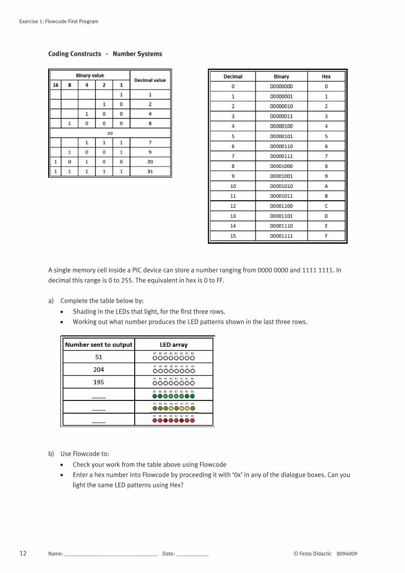
Coding Constructs - Number Systems
A single memory cell inside a PIC device can store a number ranging from 0000 0000 and 1111 1111. In
decimal this range is 0 to 255. The equivalent in hex is 0 to FF.
a) Complete the table below by:
Shading in the LEDs that light, for the first three rows.
Working out what number produces the LED patterns shown in the last three rows.
b) Use Flowcode to:
Check your work from the table above using Flowcode
Enter a hex number into Flowcode by proceeding it with ‘0x’ in any of the dialogue boxes. Can you
light the same LED patterns using Hex?
Exercise 1: Flowcode First Program
© Festo Didactic 8094009 Name: __________________________________ Date: ____________ 13
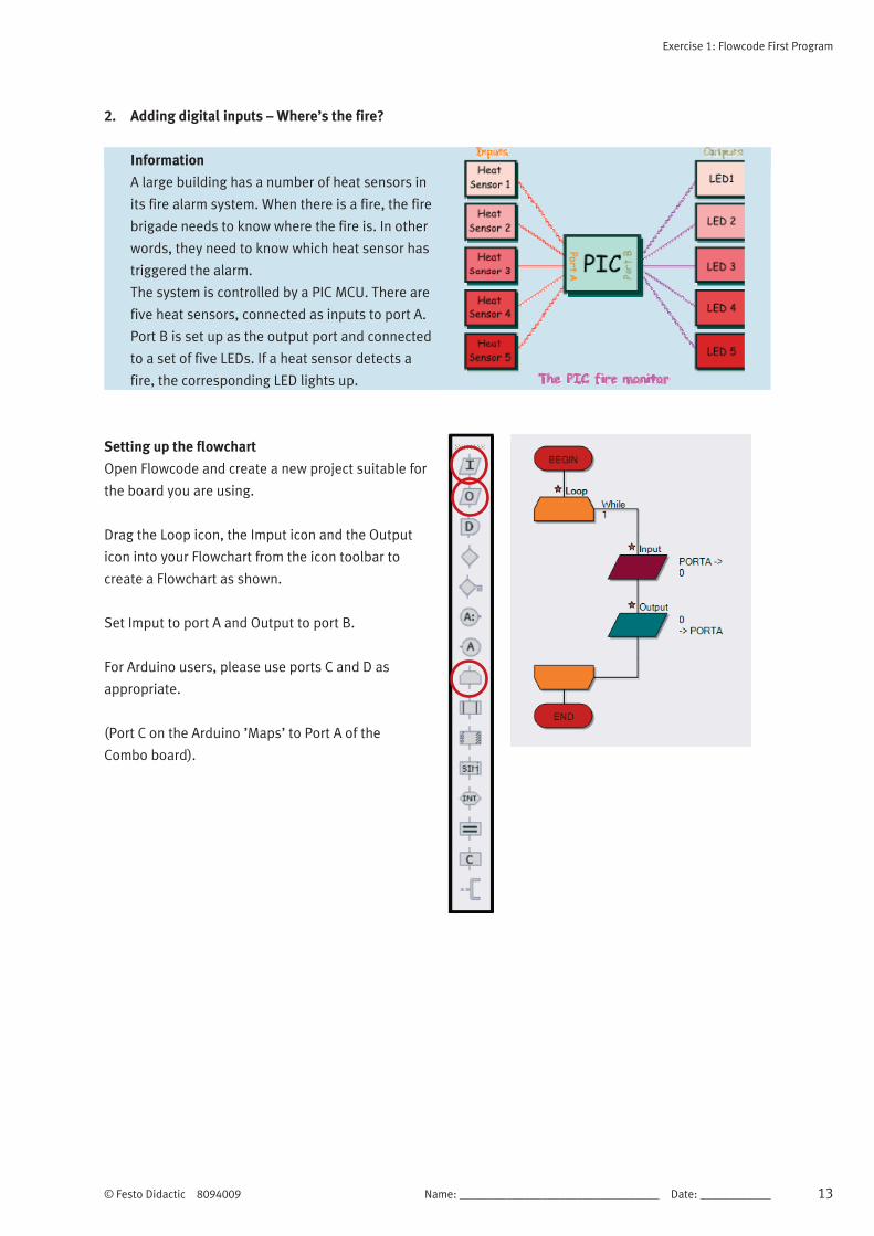
2. Adding digital inputs – Where’s the fire?
Information
A large building has a number of heat sensors in
its fire alarm system. When there is a fire, the fire
brigade needs to know where the fire is. In other
words, they need to know which heat sensor has
triggered the alarm.
The system is controlled by a PIC MCU. There are
five heat sensors, connected as inputs to port A.
Port B is set up as the output port and connected
to a set of five LEDs. If a heat sensor detects a
fire, the corresponding LED lights up.
Setting up the flowchart
Open Flowcode and create a new project suitable for
the board you are using.
Drag the Loop icon, the Imput icon and the Output
icon into your Flowchart from the icon toolbar to
create a Flowchart as shown.
Set Imput to port A and Output to port B.
For Arduino users, please use ports C and D as
appropriate.
(Port C on the Arduino ’Maps’ to Port A of the
Combo board).

Exercise 1: Flowcode First Program
14 Name: __________________________________ Date: ____________ © Festo Didactic 8094009
1. Creating the variables
a) Right-click on the input icon, and select
Properties from the menu. The Input Properties
dialogue box appears, shown opposite. This
allows us to add a variable.
But what is a variable?
A variable is a place where we can store
information, in particular, information that
changes as our program runs.
In this case, it is the number of the heat sensor
that triggers the alarm. It might be sensor 1 that
goes off, or sensor 5…. .
We are going to use a variable called SENSOR to
store the information on which sensor has been
triggered.
b) Click on the arrow next to the Variable box .
You will see the next dialogue box.
c) Now hover over the word Variables and the
arrow appear. Click on it and select Add new.
Another dialogue box, shown opposite,
appears, offering a large choice of variable
types. For now, accept the default type of Byte,
a variable which can store numbers from 0 to
255.
Type the name SENSOR as the name of the new
variable and click on the ‘OK’ button. It now
appears in the list of variables that the
flowchart can use.
d) Double-click on the name of the variable to use
it, or alternatively click and drag the name into
the variable box.
You now see the Input Properties box again.
Notice that you need to tell the system which
port you are going to use to input the data the
system needs. It is set to port A at the moment,
and we are going to leave it that way.
In this case, the system needs to monitor the
heat sensors and so each sensor will be
connected to a different bit of port A. Click on
‘OK’ to close the Input Properties box.

Exercise 1: Flowcode First Program
© Festo Didactic 8094009 Name: __________________________________ Date: ____________ 15
2. More on variables
In the previous section you added a variable to the
program using the variable dialogue box.
Computer signals consist of streams of binary 0s
and 1s on each wire. A group of eight wires can
carry eight bits, (binary digits) simultaneously. This
grouping of eight bits, known as a byte is used for
much of the internal wiring inside microcontrollers
and for the registers that hold and process data.
It is also used within memory subsystems. The
contents of a memory register having eight bits can
vary from 0 to 255.
A variable inside Flowcode can be configured to use
just one memory register or more than one.
3. Flowcode variables:
a) Flowcode offers eight different types of variables:
b) a Bool (Boolean) variable can either be 1 or 0 (true or false).
c) a single register, known as a Byte variable, can store numbers from 0 to 255.
d) a double register, known as an Int variable, can store numbers from -32768 to +32767.
e) a double register can also be unsigned, when it is known as a UInt variable, which can store numbers
from 0 to 65535.
f) a quad register, known as a Long variable, can store numbers from -2147483648 to 2147483647.
g) a quad register can also be unsigned, when it is known as a ULong variable, which can store numbers
from 0 to 4294967295.
TIP
Use a Byte variable for simple counters and for variables that will not go above the value 255. It is
the most economical in terms of memory space and also the fastest. Mathematical processes
involving two bytes (often referred to as 16 bit arithmetic) take longer to execute. A multiple
register, known as a String variable, can consist of a number of Byte variables - the default in
Flowcode is 20.
Exercise 1: Flowcode First Program
16 Name: __________________________________ Date: ____________ © Festo Didactic 8094009
1. Other variable issues
Floating point numbers (that contain a decimal point somewhere in them), can also be used, although they
represent a much wider range of values than an integer. They suffer a loss of accuracy over large ranges.
Finally an object handle is used to reference a more complicated piece of data (such as a file, component or
a block of text) whose internal format is not known.
2. Why worry?
The number of registers inside a microcontroller is limited, and in larger applications the number and types
of variables must be managed carefully to ensure that there are enough.
On downloading a program, the variables in Flowcode are implemented in the Random Access Memory
(RAM) Section of the PIC MCU. In the 16F18877 there are 4096 Bytes of memory. This means you can have
4096 Byte variables, 2048 Int variables or 204 Strings each consisting of twenty Bytes or characters.
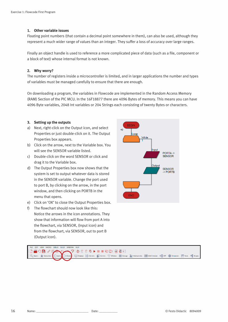
3. Setting up the outputs
a) Next, right-click on the Output icon, and select
Properties or just double-click on it. The Output
Properties box appears.
b) Click on the arrow, next to the Variable box. You
will see the SENSOR variable listed.
c) Double-click on the word SENSOR or click and
drag it to the Variable box.
d) The Output Properties box now shows that the
system is set to output whatever data is stored
in the SENSOR variable. Change the port used
to port B, by clicking on the arrow, in the port
window, and then clicking on PORTB in the
menu that opens.
e) Click on ‘OK’ to close the Output Properties box.
f) The flowchart should now look like this:
Notice the arrows in the icon annotations. They
show that information will flow from port A into
the flowchart, via SENSOR, (Input icon) and
from the flowchart, via SENSOR, out to port B
(Output icon).

Exercise 1: Flowcode First Program
© Festo Didactic 8094009 Name: __________________________________ Date: ____________ 17
4. Adding the LEDs
a) Now click on the Outputs button and select the
LED Array (PCB) icon. Click-and-drag it onto the
System Panel.
b) Change the Count property under the
Simulation section to the value 5 by clicking on
the box next to the Count property and using
the keyboard to input the value.
c) Click next to Port under the Connections section
to open an interactive view of the chip, showing
the compatible pins.
d) Click on the drop-down menu and select the
PORT B option. You have now connected the
LEDs to the pins on port B.
(For Arduino users, please use ports C and D as
appropriate).
5. Adding the switches
a) You are going to use five switches to simulate the five heat sensors. The switch that is ‘on’ (closed) is
the heat sensor that has triggered the fire alarm.
b) Click on the Inputs button and select the Switch Array (slide). Drag it into a suitable spot on the System
Panel.
c) Click on the box next to the Count property and change the value to 5. Check that the component is
connected to PORTA.
6. Simulating the program
a) Click once on the Step Into button. The Simulation Debugger window appears but ignore it for now.
b) Move the cursor over one of the switches and click, to simulate detecting a fire. The switch graphic
toggles to the closed position. Click the Step Into button a few more times to simulate the complete
program.
The program is finished. You have just detected a fire, which turned on a heat sensor.
The LED array tells you, or the fire brigade, which sensor detected the fire.

Exercise 1: Flowcode First Program
18 Name: __________________________________ Date: ____________ © Festo Didactic 8094009

© Festo Didactic 8094009 Name: __________________________________ Date: ____________ 19
Exercise 2: Using loops – Counting sheep
Description of the problem
Counting sheep, badly at first, but without falling asleep!
The plan is straightforward - when a sheep passes through the gate, it breaks a light beam. This sends a
pulse to a counting system, which then adds one to the total stored in the system.
We display this total on the LED array.
(Note that Flowcode has a Beam Breaker component, based on the Collision Detector. Although this would
do a far better job, for now we detect the light beam interruption using more basic methods).
Exercise 2: Using loops – Counting sheep
20 Name: __________________________________ Date: ____________ © Festo Didactic 8094009
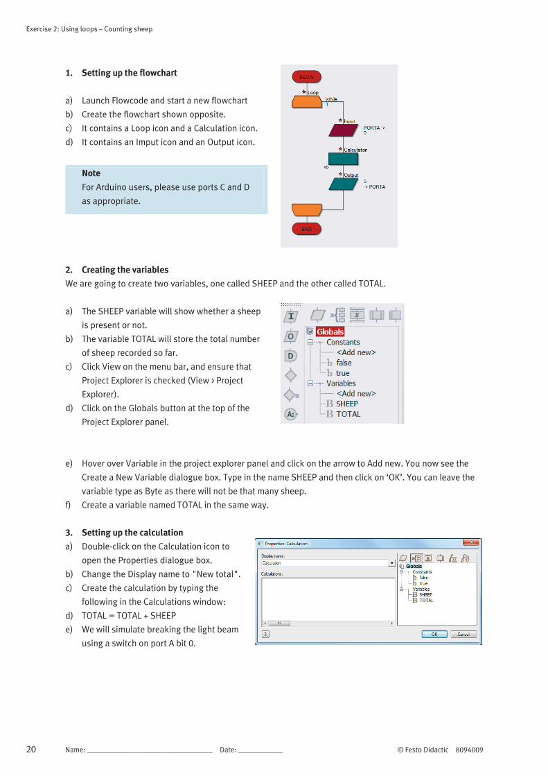
1. Setting up the flowchart
a) Launch Flowcode and start a new flowchart
b) Create the flowchart shown opposite.
c) It contains a Loop icon and a Calculation icon.
d) It contains an Imput icon and an Output icon.
Note
For Arduino users, please use ports C and D
as appropriate.
2. Creating the variables
We are going to create two variables, one called SHEEP and the other called TOTAL.
a) The SHEEP variable will show whether a sheep
is present or not.
b) The variable TOTAL will store the total number
of sheep recorded so far.
c) Click View on the menu bar, and ensure that
Project Explorer is checked (View > Project
Explorer).
d) Click on the Globals button at the top of the
Project Explorer panel.
e) Hover over Variable in the project explorer panel and click on the arrow to Add new. You now see the
Create a New Variable dialogue box. Type in the name SHEEP and then click on ‘OK’. You can leave the
variable type as Byte as there will not be that many sheep.
f) Create a variable named TOTAL in the same way.
3. Setting up the calculation
a) Double-click on the Calculation icon to
open the Properties dialogue box.
b) Change the Display name to "New total".
c) Create the calculation by typing the
following in the Calculations window:
d) TOTAL = TOTAL + SHEEP
e) We will simulate breaking the light beam
using a switch on port A bit 0.
Exercise 2: Using loops – Counting sheep
© Festo Didactic 8094009 Name: __________________________________ Date: ____________ 21
f) The Input properties are set up to store whatever number appears on port A in the variable called
SHEEP. Initially, that number is 0. When the switch is pressed, the number on port A and stored in the
variable SHEEP is 1 (with only one switch, the biggest number we can create on port A is 1).
g) When the Calculation icon is executed, the number stored in the variable SHEEP is added to the TOTAL
variable. Hence, when a sheep breaks the light beam, TOTAL is increased by 1. With no sheep present,
TOTAL remains unchanged.
h) Click on the ‘OK’ button, to close the dialogue box
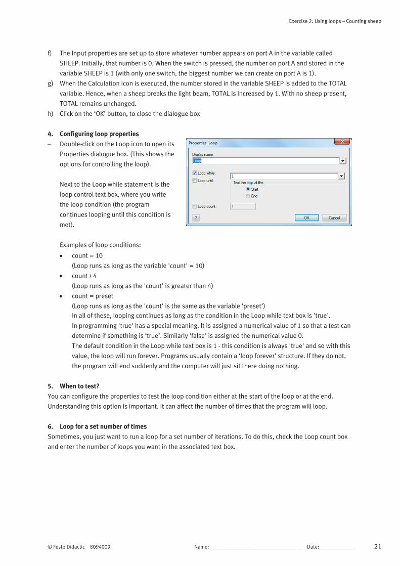
4. Configuring loop properties
– Double-click on the Loop icon to open its
Properties dialogue box. (This shows the
options for controlling the loop).
Next to the Loop while statement is the
loop control text box, where you write
the loop condition (the program
continues looping until this condition is
met).
Examples of loop conditions:
count = 10
(Loop runs as long as the variable 'count' = 10)
count > 4
(Loop runs as long as the 'count' is greater than 4)
count = preset
(Loop runs as long as the 'count' is the same as the variable ‘preset’)
In all of these, looping continues as long as the condition in the Loop while text box is 'true'.
In programming 'true' has a special meaning. It is assigned a numerical value of 1 so that a test can
determine if something is ‘true’. Similarly 'false' is assigned the numerical value 0.
The default condition in the Loop while text box is 1 - this condition is always 'true' and so with this
value, the loop will run forever. Programs usually contain a ‘loop forever’ structure. If they do not,
the program will end suddenly and the computer will just sit there doing nothing.
5. When to test?
You can configure the properties to test the loop condition either at the start of the loop or at the end.
Understanding this option is important. It can affect the number of times that the program will loop.
6. Loop for a set number of times
Sometimes, you just want to run a loop for a set number of iterations. To do this, check the Loop count box
and enter the number of loops you want in the associated text box.

Exercise 2: Using loops – Counting sheep
22 Name: __________________________________ Date: ____________ © Festo Didactic 8094009
7. Setting up the input
a) Right-click on the Input icon, and select
Properties from the menu, to see the
following dialogue box:
b) Change the display name. Double-click
on Input in the Display name box and
type "Check the sensor".
c) Click on the arrow next to the Variable
box to open the Variable Manager.
d) Double-click on the word 'SHEEP' to
insert it into the Variable box.
e) By default, the input is port A, which is
what we want, Click on ‘OK’ to close the
dialogue box.
Note
Arduino use PORTC.
8. Setting up the output
a) Double-click on the Output icon to open
the output Properties dialogue box.
b) Click on the arrow next to the Variable
box.
c) Double-click on the word TOTAL to insert
it into the Variable box.
d) In the output Properties box, change the
port used to PORTB.
e) Click on 'OK' to close the dialogue box.
The flowchart should now look like this:
Note
For Arduino users, please use ports C and D as appropriate.

Exercise 2: Using loops – Counting sheep
© Festo Didactic 8094009 Name: __________________________________ Date: ____________ 23
9. Adding the LED array
a) Click once on the Outputs box and select the LED Array icon. Place it on the System Panel by moving the
cursor over it and then ‘clicking-and-dragging’ it into position.
b) Change the value of the Count property to 8 to set the number of LEDs in the array.
c) Click the Connections property in the Properties pane. Select PORTB from the drop-down menu to
connect the LEDs to the pins on port B.
d) You can change the colour of the LED array in the Colors section.
10. Adding the switch
a) A single push switch will represent the light beam sensor.
b) Click once on the Input box and select Switch (Push,Panel) icon. Add or drag it onto the System Panel.
c) On the Properties pane Connections section, check that the Connection property for the switch is
$PORTA.0 i.e. the switch is connected to port A bit 0.
d) Goto > Shapes > Label in the System Panel toolbar to create text.
e) Click on the Label property in the Properties pane and replace the default text with "Light beam
interruption".
f) To adjust the size of the text, click on the Position tab and change the values of ‘Width’ and ‘Height’
under the ‘World size’ section. Move the text to a suitable position next to the switch.
11. Simulating the program
a) Now run the simulation by clicking on the Run button.
b) The Simulation debugger window appears - close it as it is not needed.
c) Move the cursor over the switch and give the briefest mouse click you can.
What happens depends on how quickly you click, and how fast the PC works.
We want only the B0 LED to light, to show a total of 1 sheep. The program runs at high speed, however,
and so keeps cycling through the Input and Calculation steps. As a result, before you have time to
release the push switch, the total has incremented (increased by one) several times. This problem is
explored in the next section.
Exercise 2: Using loops – Counting sheep
24 Name: __________________________________ Date: ____________ © Festo Didactic 8094009
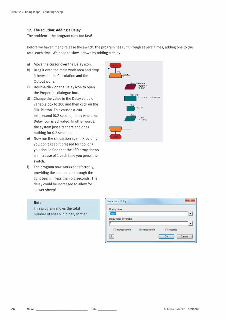
12. The solution: Adding a Delay
The problem – the program runs too fast!
Before we have time to release the switch, the program has run through several times, adding one to the
total each time. We need to slow it down by adding a delay.
a) Move the cursor over the Delay icon.
b) Drag it onto the main work area and drop
it between the Calculation and the
Output icons.
c) Double-click on the Delay icon to open
the Properties dialogue box.
d) Change the value in the Delay value or
variable box to 200 and then click on the
‘OK’ button. This causes a 200
millisecond (0.2 second) delay when the
Delay icon is activated. In other words,
the system just sits there and does
nothing for 0.2 seconds.
e) Now run the simulation again. Providing
you don't keep it pressed for too long,
you should find that the LED array shows
an increase of 1 each time you press the
switch.
f) The program now works satisfactorily,
providing the sheep rush through the
light beam in less than 0.2 seconds. The
delay could be increased to allow for
slower sheep!
Note
This program shows the total
number of sheep in binary format.

© Festo Didactic 8094009 Name: __________________________________ Date: ____________ 25
Exercise 3: The LCD display – Posting messages
Description of the problem
Programs using the LCD display need to use the crystal oscillator. If necessary, in Flowcode, select Build
from the main menu, then Project Options and finally the Configure tab. Select the crystal oscillator from the
list of options (Build > Project Options >Configure).
Layout

Exercise 3: The LCD display – Posting messages
26 Name: __________________________________ Date: ____________ © Festo Didactic 8094009
1. LCD displays
Flowcode comes with a number of components that add commonly used subsystems to Flowcode, such as
the LCD display, 7-segment display, and analogue inputs devices.
Here, we look at the LCD display, the basic text display subsystem on a range of electronics devices, from
calculators to mobile phones. It can display text or numbers on one or more rows of the display.
In most programming languages, the LCD is one of the last things you learn, as it is quite a complicated
device to program. However, Flowcode takes care of the complexities, making the LCD simple to use. The
LCD display referred to here is the one used on the E-Blocks Combo board and on the LCD display - a four
row, twenty character display.
2. Adding the LCD component
Before you can use the LCD, you need to add a LCD component to a Flowcode panel. To do so, click on the
Displays box, select the LCD (Generic, 20x4) component from the menu and add it to the System Panel. A
LCD display mimic will now appear on the panel.
At the top of the Properties pane, the Component section identifies the component you have just selected.
By default, the LCD is added to port B.
The LCD display requires five connections. It displays letters and numbers conveyed as serial data on this
five wire bus. The techniques involved go beyond this tutorial. Fortunately, Flowcode has some embedded
routines that take care of the complexities.
Drag a Component Macro icon onto the
flowchart and open up the corresponding
macro dialogue box by double-clicking on it.
Now scroll through the LCD section in
Components and select the macro called
Start. This initiates the LCD, clears the
display and gets it ready for action. We
examine more LCD macros in the next couple
of sections, but for now scroll through the
available macros and take a quick look at
each.

Exercise 3: The LCD display – Posting messages
© Festo Didactic 8094009 Name: __________________________________ Date: ____________ 27
3. Writing messages
To display text on the LCD, simply type it in.
a) Add another Component Macro to the
flowchart and open the macro dialogue
box.
b) Select the LCD macro called PrintString.
This requires a single parameter (item of
data), 'Text' (the text to be printed).
c) Type the text into the parameter box
surrounded by quotation marks, e.g.
"Hello World"
d) Run the program and the text will be sent
to the LCD display.
4. Othe LCD functions
There are a number of other useful functions in the LCD macro list:
a) Clear – Clears the display and resets the cursor position (where the display prints next,) to '0,0' i.e. top
left.
b) Cursor – Moves the cursor to the specified location. The two parameters, ‘X’ and ‘Y’ select the horizontal
and vertical positions of the cell respectively. ‘0,0’ is the top left cell, ‘0,1’ the first cell on the second
line, ‘3,2’ the fourth cell on the third line etc.
c) PrintNumber – Works like 'PrintString' but prints a number instead of a string. It can be used with
variables, or with actual numbers.
Exercise 3: The LCD display – Posting messages
28 Name: __________________________________ Date: ____________ © Festo Didactic 8094009
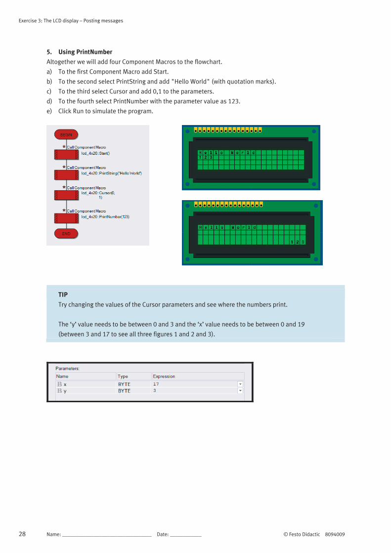
5. Using PrintNumber
Altogether we will add four Component Macros to the flowchart.
a) To the first Component Macro add Start.
b) To the second select PrintString and add "Hello World" (with quotation marks).
c) To the third select Cursor and add 0,1 to the parameters.
d) To the fourth select PrintNumber with the parameter value as 123.
e) Click Run to simulate the program.
TIP
Try changing the values of the Cursor parameters and see where the numbers print.
The ‘y’ value needs to be between 0 and 3 and the ‘x’ value needs to be between 0 and 19
(between 3 and 17 to see all three figures 1 and 2 and 3).
© Festo Didactic 8094009 Name: __________________________________ Date: ____________ 29
Exercise 4: Stopwatch
This excercise uses excercise 5 (Using PrintNumber) as a starting point.
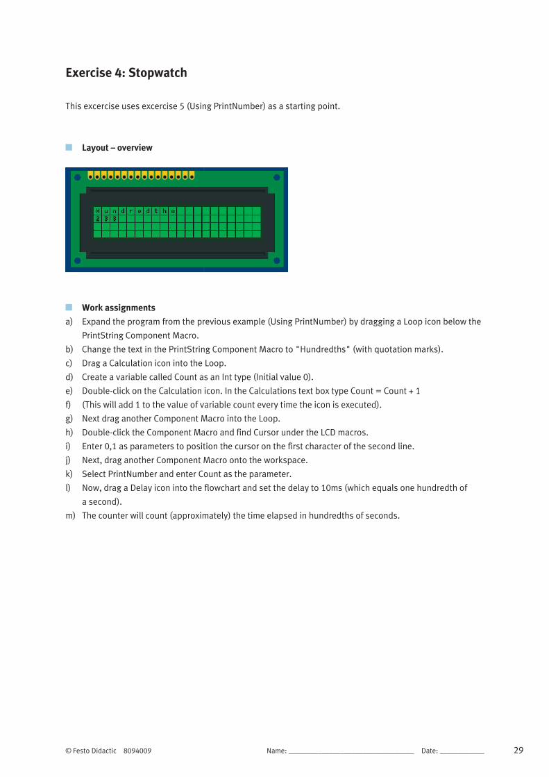
Layout – overview
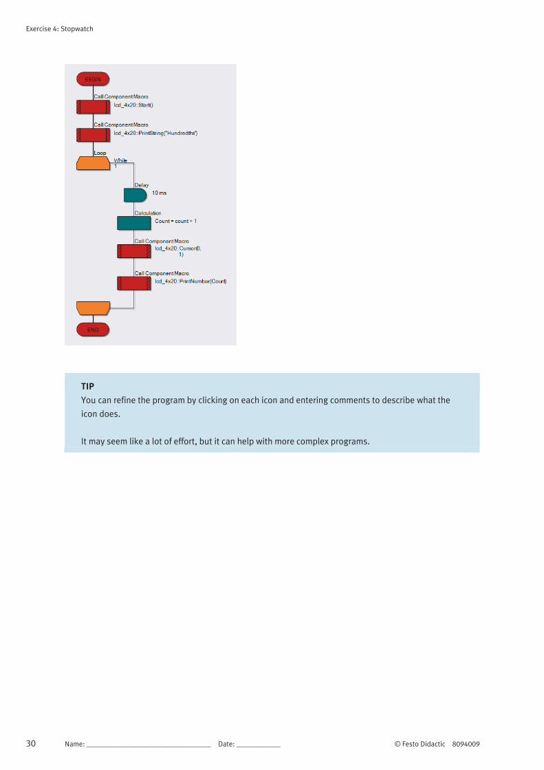
Work assignments
a) Expand the program from the previous example (Using PrintNumber) by dragging a Loop icon below the
PrintString Component Macro.
b) Change the text in the PrintString Component Macro to "Hundredths" (with quotation marks).
c) Drag a Calculation icon into the Loop.
d) Create a variable called Count as an Int type (Initial value 0).
e) Double-click on the Calculation icon. In the Calculations text box type Count = Count + 1
f) (This will add 1 to the value of variable count every time the icon is executed).
g) Next drag another Component Macro into the Loop.
h) Double-click the Component Macro and find Cursor under the LCD macros.
i) Enter 0,1 as parameters to position the cursor on the first character of the second line.
j) Next, drag another Component Macro onto the workspace.
k) Select PrintNumber and enter Count as the parameter.
l) Now, drag a Delay icon into the flowchart and set the delay to 10ms (which equals one hundredth of
a second).
m) The counter will count (approximately) the time elapsed in hundredths of seconds.
Exercise 4: Stopwatch
30 Name: __________________________________ Date: ____________ © Festo Didactic 8094009
TIP
You can refine the program by clicking on each icon and entering comments to describe what the
icon does.
It may seem like a lot of effort, but it can help with more complex programs.

© Festo Didactic 8094009 Name: __________________________________ Date: ____________ 31
Excercise 5: Using binary numbers – A binary calculator
Description of the problem
In this section you build a binary adder - a system that makes the microcontroller add two numbers.
The simplest way to input a binary number is to use a set of switches attached to the input port.
To input two numbers, we need two sets of switches and two input ports.
To see the result of the calculation, we will use an LED array, connected to the output port.
We need a microcontroller with three ports.
Layout – overview

Excercise 5: Using binary numbers – A binary calculator
32 Name: __________________________________ Date: ____________ © Festo Didactic 8094009
1. Setting up the flowchart
a) Launch Flowcode and start a new flowchart.
b) This time we take notice of this dialogue box:
c) We need a microcontroller with at least three
ports.
d) Pull the slide bar down to find the 16F18877PIC
MCU.
e) Click on it to select it and then click on ‘OK’.
f) Click-and-drag a Loop icon.
g) Click-and-drag an Input icon and drop it
between the ends of the loop.
h) Click and drag a second Input icon and drop it in
between the ends of the loop.
i) Click and drag an Output icon and drop it just
below the Input boxes.
j) Click and drag a Calculation icon, and place it in
between the second Input icon and the Output
icon.
k) Your flowchart will look similar to this:
(the example image has descriptions and
variables added).
2. Creating the variables
a) Click View on the menu bar and ensure that Project Explorer is checked (View > Project Explorer).
b) Click on the Globals button at the top of the Project Explorer panel.
c) We are going to create three variables, called input1, input2 and sum. The first two store the numbers
fed in from the switches. The variable sum stores the result of adding them together.
d) Hover over Variables in the Project Explorer panel then click on the arrow that appears.
e) Click Add new and the Create a New Variable dialogue box appears. Type in the name input1, and click
on the ‘OK’ button - leave the variable type as Byte.
f) Create variables, input2 and sum in the same way.

Excercise 5: Using binary numbers – A binary calculator
© Festo Didactic 8094009 Name: __________________________________ Date: ____________ 33
3. Setting up the inputs
a) Right-click on the top Input icon, and select
Properties.
The Properties: Input dialogue box appears.
b) Double-click on the word Input in the Display
name box to highlight it.
c) Type ‘Input the first number’ to replace it. This
will appear alongside the Input icon in the
flowchart.
(Adding labels like this helps users to
understand what is happening). d) Click on the arrow next to the variable box to
open the Variable Manager.
This lists the three variables that you just
created.
e) Double-click on input1 to use this variable in
the input box.
f) Back in the Input Properties dialogue box, click
on the down arrow at the end of the port
window and select PORTB to replace PORTA.
g) Click on ‘OK’ to close the dialogue box.
h) Double-click on the second Input icon, (a
quicker way to open the Properties box.)
Configure this input to:
i) display the label ‘Input the second number’
j) use the variable input2
k) use PORTC.
l) Then close the dialogue box by clicking the ‘OK’
button.
Note
For Arduino users, these two Ports will need to be set as follows:
Input 1 set to PORTC (to use the Port A switches on the Combo board).
Input 2 set to PORTD (to use the Port B switches on the Combo board).
Excercise 5: Using binary numbers – A binary calculator
34 Name: __________________________________ Date: ____________ © Festo Didactic 8094009
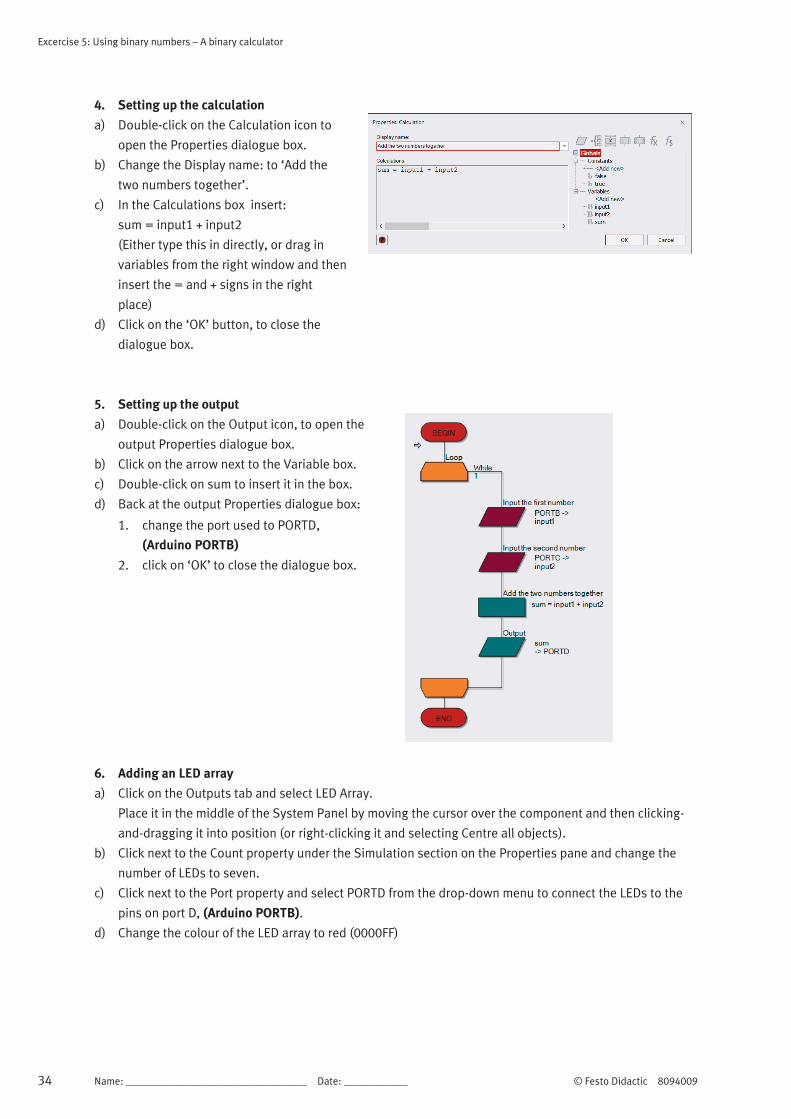
4. Setting up the calculation
a) Double-click on the Calculation icon to
open the Properties dialogue box.
b) Change the Display name: to ‘Add the
two numbers together’.
c) In the Calculations box insert:
sum = input1 + input2
(Either type this in directly, or drag in
variables from the right window and then
insert the = and + signs in the right
place)
d) Click on the ‘OK’ button, to close the
dialogue box.
5. Setting up the output
a) Double-click on the Output icon, to open the
output Properties dialogue box.
b) Click on the arrow next to the Variable box.
c) Double-click on sum to insert it in the box.
d) Back at the output Properties dialogue box:
1. change the port used to PORTD,
(Arduino PORTB)
2. click on ‘OK’ to close the dialogue box.
6. Adding an LED array
a) Click on the Outputs tab and select LED Array.
Place it in the middle of the System Panel by moving the cursor over the component and then clicking-
and-dragging it into position (or right-clicking it and selecting Centre all objects).
b) Click next to the Count property under the Simulation section on the Properties pane and change the
number of LEDs to seven.
c) Click next to the Port property and select PORTD from the drop-down menu to connect the LEDs to the
pins on port D, (Arduino PORTB).
d) Change the colour of the LED array to red (0000FF)
Excercise 5: Using binary numbers – A binary calculator
© Festo Didactic 8094009 Name: __________________________________ Date: ____________ 35
7. Adding the switches
Two sets of switches are used, one for each binary number. The output port has only eight bits. The biggest
number it can output is 1111 1111 (= 255 in decimal). We are going to limit ourselves to inputting seven bit
numbers meaning that the biggest number we can input is 111 1111 (= 127 in decimal). If we used bigger
numbers, we would overflow the capacity of the output.
a) Click on the Inputs tab, select Switch Array (Slide) and drag it onto the System Panel above the LED
array.
b) Open the Properties pane for the Switch Array
(Slide). Connect it to port B, using the arrow
next to the Port property to open the drop down
menu (Arduino PORTC).
c) Add a second Switch Array (Slide) to the System
Panel in the same way. Position it under the LED
Array and connect it to PORTC
(Arduino PORTD).
8. Slow simulation
As described earlier, Flowcode allows you to progress through the flowchart one step/icon at a time, to see
the effect of each on the variables and on the output. a) There are three ways to simulate the program step-by-step:
1. Click on Run on the Main toolbar and on the Step Into button (Run > Step Into)
2. Press the F8 function key on the keyboard.
3. Click on the Step Into button on the main toolbar in the simulation section.
Several things happen:
4. a red rectangle appears around the BEGIN icon, showing that this is the current step.
5. the Simulation debugger window appears (containing Variables and Macro Calls).
6. the Variables section lists the three variables that you defined for this program, and shows their
current values (all zero at the moment).
Ignore the Macro Calls section for the moment.
Now set up two numbers on the switch components.
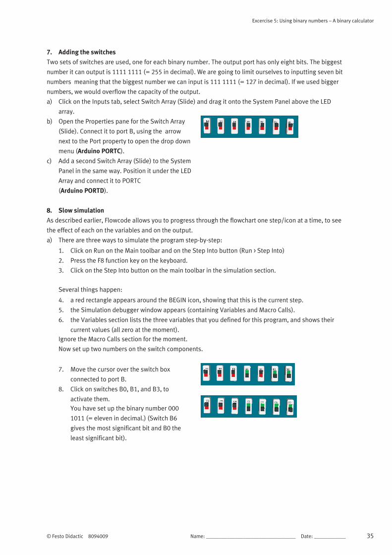
7. Move the cursor over the switch box
connected to port B.
8. Click on switches B0, B1, and B3, to
activate them.
You have set up the binary number 000
1011 (= eleven in decimal.) (Switch B6
gives the most significant bit and B0 the
least significant bit).

Excercise 5: Using binary numbers – A binary calculator
36 Name: __________________________________ Date: ____________ © Festo Didactic 8094009
b) Set up the number 000 1111 (fifteen) on the switches connected to port C.
c) Now Step Into to the next icon in the program by, for example, pressing F8 once more.
d) The red rectangle moves on to the next icon, the Loop icon, but little else happens.
e) Press F8 once again. The red rectangle moves on to the first Input icon.
f) Press F8 again and the Variables box shows that the input1 variable now contains eleven (the result of
the Input instruction just carried out).
g) Press F8 again and the Variables section shows that input now contains fifteen.
h) Press F8 again and the calculation is carried out. The sum variable stores the result.
i) Press F8 again. The value stored in sum is transferred to the LED array.
j) It looks like:
k) Reading from the most significant bit (D6) to the least significant bit (D0), the LED array shows the
number 001 1010. In decimal, this is the number 26. No surprises there then.
l) Repeat the same procedure using different numbers and step through the program to check what the
sum of the numbers is.
TIP
TIP: Explore adding graphics to your binary calculator to make it easier to read.
Goto > Shapes > Labels to add digits above your LEDs.

© Festo Didactic 8094009 Name: __________________________________ Date: ____________ 37
Excercise 6: Binary logic in control
Description of the problem
Electronic systems can make decisions.
Very often, these are of the form "If this AND this is true, then..." or "If this OR this is true, then...". They
rely on specific combinations of circumstances in order to take some particular action.
They are examples of using binary logic. The answer to the “If…” question is either “Yes” / “No”, or “True” /
“False”, i.e. one of two possibilities (a binary solution). This answer could be expressed as a logic 0 or a
logic 1 and electronically by a high voltage or a low voltage.
There is a class of digital electronic components, called logic gates, that perform exactly these decisions.
The inputs and output are logic 0 or logic 1.
We can program Flowcode to make exactly the same decisions.

Excercise 6: Binary logic in control
38 Name: __________________________________ Date: ____________ © Festo Didactic 8094009

© Festo Didactic 8094009 Name: __________________________________ Date: ____________ 39
Exercise 6-1: Controlling a microwave oven
For reasons of safety, a microwave oven has a door sensor to make sure that the microwave generator will
not operate if the door is open. Put another way, the generator operates if the door is closed AND one of the
heating control switches is pressed.
We can build this condition into a Flowcode program.
1. Setting up a flowchart
Launch Flowcode with a new flowchart.
Create the flowchart shown opposite. It uses:
a) a loop icon
b) two input icons
c) three output icons
d) two decision icons
e) two calculation icons f) a delay icon.
Create four variables:
a) ‘door’ (to store the state of the door switch).
b) ‘control’ (to store the state of the on/off
control switch)
c) ‘output’ (to control whether the microwave
switches on or not)
d) ‘count’ (to monitor how many times the 1s
delay has occurred. Give it an initial value of
ten, so that the microwave oven will operate
for 9s).
e) Use the default configuration for the loop icon.
f) Configure one input icon to store the state of
the door switch (on port A bit 0) in the variable
‘door’
g) Configure the other input icon to store the state
of the control switch (on port A bit 1) in the
variable ‘control’.
h) The upper calculation icon checks to see
whether the door AND the control switch have
been pressed.

Exercise 6-1: Controlling a microwave oven
40 Name: __________________________________ Date: ____________ © Festo Didactic 8094009
Configure it using the equation output = control & door.
The & signifies the AND operation.
The result of this operation (0 or 1) is stored in the variable ‘output’.
i) The upper decision icon checks the value stored in ‘output’.
(If output? is shorthand for If output=1?)
Configure this decision icon.
When the result of the calculation is 0, the program follows the ‘No’ route from the decision icon and the
left-hand output icon is executed. This sends a logic 0 to the LED, ensuring that it (and the microwave
generator) is switched off.
j) When the result of the calculation is 1, the program follows the ‘Yes’ route. The ‘Turn on’
output icon sends a logic 1 to the LED turning it on.
Configure both of these output icons.
k) The lower calculation icon reduces the number stored in the variable ‘count’ by one.
Configure it using the equation count = count - 1
l) The initial value of ‘count’ is ten. Provided the
number stored in ‘count’ has not reached zero,
the program follows the ‘No’ route. Eventually,
after looping enough times, the number stored
does reduce to zero. The program then follows
the ‘Yes’ route and executes the ‘Turn off’
output icon, which is configured in the same
way as the other ‘Turn off’ icon, to switch off the
microwave generator.
m) Add a switch array to the System Panel. Configure it to have only two switches, one connected to port A,
bit 0 and the other to port A, bit 1.
n) Add an LED connected to port B, bit 0 to represent the microwave generator.
o) Add labels to the System Panel to identify the components.
Position them using the World coordinates under the Position tab of the label properties.
p) Now simulate the program step-by-step, using the F8 function key repeatedly.
q) Check what happens for different combinations of switch states and interpret this in terms of the
behaviour of the microwave oven. What happens, for example, if the door is opened while the
microwave generator is operating?
Note
For Arduino users, the Ports need to be set to PORTC and PORTD (equivalent to A and B on the
Combo board).

© Festo Didactic 8094009 Name: __________________________________ Date: ____________ 41
Excercise 6-2: Car
Description of the problem
Electronic systems can make decisions.
Very often, these are of the form "If this AND this is true, then..." or "If this OR this is true, then...". They
rely on specific combinations of circumstances in order to take some particular action.
They are examples of using binary logic. The answer to the “If…” question is either “Yes” / “No”, or “True” /
“False”, i.e. one of two possibilities (a binary solution). This answer could be expressed as a logic 0 or a
logic 1 and electronically by a high voltage or a low voltage.
There is a class of digital electronic components, called logic gates, that perform exactly these decisions.
The inputs and output are logic 0 or logic 1.
We can program Flowcode to make exactly the same decisions.
Layout – overview
Controlling the interior light in the car
The interior light of a car can be controlled by another Boolean logic equation.
For simplicity, consider a two-door car with the following behaviour:
The interior light turns on when one door (A) OR the other (B) is opened and stays on until the ignition
switch (C) is turned on.
In Boolean-speak, we say that the light is on if (A OR B) AND NOT C is true.
Once again, we can build this condition into a Flowcode program.

Excercise 6-2: Car
42 Name: __________________________________ Date: ____________ © Festo Didactic 8094009
1. Setting up a flowchart
Launch Flowcode and start a new flowchart.
Create the flowchart shown opposite, using:
a) a loop icon.
b) three input icons.
c) two output icons.
d) a decision icon.
e) a calculation icon.
Create four variables:
a) ‘door_A’ (to store the state of the switch on
door A).
b) ‘door_B’ (to store the state of the switch on
door B).
c) ‘ig_switch’ (to store the state of the ignition
switch).
d) ‘output’ (to control whether the interior light
switches on or not).
e) Use the default configuration for the loop icon.
f) Configure one input icon to store the state of
the switch on door A (port A bit 0), in the
variable ‘door_A’.
g) Configure one input icon to store the state of
the switch on door B (port A bit 1) in the
variable ‘door_B’.
h) Configure the other input icon to store the state
of the ignition switch (port A bit 2) in the
variable ‘ig_switch’.
The calculation icon checks to see whether either door has been opened AND the ignition switch is NOT on.
i) Configure it using the equation output = (door_A ||door_B) & !ig_switch
The || signifies the OR operation and ! the NOT operation. The result of the calculation is stored in the
variable ‘output’.
Note
For Arduino users, please use ports C and D as appropriate.
Excercise 6-2: Car
© Festo Didactic 8094009 Name: __________________________________ Date: ____________ 43
j) The decision icon checks the value stored in ‘output’.
k) Configure this decision icon.
l) When the result of the calculation is 0, the program follows the ‘No’ route from the decision icon and the
'Turn Off' output icon is executed, ensuring that the light is switched off.
m) When the result of the calculation is 1, the program follows the ‘Yes’ route. The ‘Turn on’ output icon
sends a logic 1 to the LED turning it on.
n) Configure both of these output icons.
o) Add a switch array to the System Panel. Configure it to have three switches, one connected to port A, bit
0, one to portA, bit 1 and the other to port A, bit 2.
p) Add an LED connected to port B, bit 0 to represent the interior light in the car.
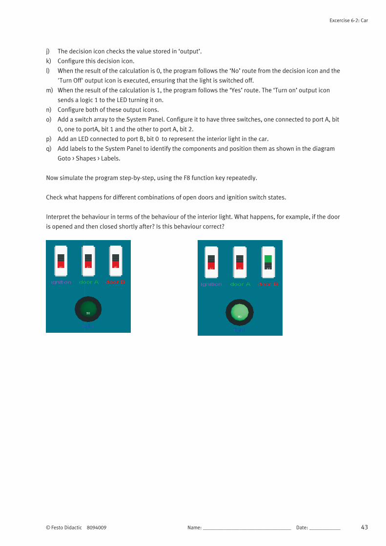
q) Add labels to the System Panel to identify the components and position them as shown in the diagram
Goto > Shapes > Labels.
Now simulate the program step-by-step, using the F8 function key repeatedly.
Check what happens for different combinations of open doors and ignition switch states.
Interpret the behaviour in terms of the behaviour of the interior light. What happens, for example, if the door
is opened and then closed shortly after? Is this behaviour correct?

Excercise 6-2: Car
44 Name: __________________________________ Date: ____________ © Festo Didactic 8094009

© Festo Didactic 8094009 Name: __________________________________ Date: ____________ 45
Excercise 7: Programming Excercises
Information
The Programming Exercises are presented here as flexible tasks suitable for further development.
Small, individual tasks can be developed into larger scale projects if desired. Try out the ideas, test them,
experiment, develop your skills and see what you can create.
The aim of the exercises is to develop experience in using Flowcode and in the process, develop
understanding of the programming terminology and techniques it embraces.
Programs can be tested by simulating them in Flowcode, but also downloaded to a microcontroller and
tested on hardware. It is generally assumed that the programmer is using a Microchip PIC MCU though the
exercises are equally applicable to other microcontrollers.
The section ends with further Challenges. These are even more open-ended and contain only a brief
specification.

Excercise 7: Programming Exercises
46 Name: __________________________________ Date: ____________ © Festo Didactic 8094009
© Festo Didactic 8094009 Name: __________________________________ Date: ____________ 47
Excercise 7-1: Programming Excercises – Creating outputs
Objectives
Change the logic level of a one single pin of a port.
Send different 8-bit codes to the port of a microcontroller.
Configure an Output icon.
Use binary code.
Manipulate logic output levels.
Use LEDs to display an output.
Compile a program to a microcontroller.
Tasks
1. Create a Flowcode flowchart then see if you can
a) add a single Output icon, configured to light all the LEDs of a port and run the simulation.
b) alter the parameters to light only the odd-numbered LEDs and run the simulation.
c) light only the even-numbered LEDs.
d) light only the high ‘nibble’ bits (4 to 7) of the chosen port.
Modify this program and see if you can:
a) repeat the previous steps using hexadecimal rather than decimal numbering.
b) only light the LED on bit 7, by sending an 8-bit value to the port.
c) only light the LED on bit 7, using the 'single bit' output method.
d) only light the LED on bit 7, using the 'masking' output method.
2. Write a program that uses at least twenty Output icons to write different values to port B, one after
the other. Use all four methods in this exercise - hexadecimal, decimal, single bit and masking.
Simulate the program and review the results. (Save the program and download it to the
microcontroller).
TIP
Restart the program a number of times by pressing the Reset button on the programmer board.
48 Name: __________________________________ Date: ____________ © Festo Didactic 8094009
Excercise 7-2: Programming Excercises – Using Delays
Information
In this exercise, you learn how delays are used to slow down program execution. Microcontrollers work
extremely quickly - typically executing about 5,000,000 assembly instructions, every second.
A human can detect and understand only around three stable images per second.
To allow a high-speed microcontroller to communicate with ‘slow’ humans, we sometimes need
to slow it down by adding Delay instructions.
Objectives
Add a delay to slow down execution of a program.
Change the delay interval.
Configure a delay icon.
Control the speed of a microcontroller.
Use an oscilloscope to time events .
Tasks
1. Begin by opening the program created in the last exercise (Exercise 7-1).
a) Add Delay icons and configure them so that the output states can be viewed comfortably even at
‘HS oscillator’ speed.
b) Save the program and download it to the microcontroller, testing the program on the E-blocks
boards.
Modify the length of the delays caused by the Delay icons.
c) Start with a delay of 1s.
d) Progressively reduce the delay until it is too fast for your eyes to detect the different output states.
e) Download the program to the microcontroller every time and test it on E-blocks.
f) Use an oscilloscope to measure the delays you set up in Flowcode.
g) Make a detailed drawing of the oscilloscope image, complete with voltage and timing information
and the delay time used in the Flowcode program.
TIP
Do not test this in simulation mode - simulation timing is not always accurate because it runs under
a Windows operating system and not in ‘real time’.

© Festo Didactic 8094009 Name: __________________________________ Date: ____________ 49
Excercise 7-3: Programming Excercises – Using Connection Points
Information
A Connection Point, or ‘goto’ instruction, is often used to create an infinite loop - to repeat a set of
instructions over and over again (a better way to do this is to use a ‘Loop’ instruction). The advantage of a
Connection Point is that it can be used to jump out of a loop to a certain location in the program. The idea of
pulse-width modulation (PWM) is introduced as a means of controlling LED brightness.
Objectives
Use Connection Points to introduce unconditional branching in a program.
Introduce PWM as a means of controlling the brightness of LEDs.
Create an infinite loop.
Manipulate logic output levels.
Use LEDs to display an output.
Tasks
1. Write a program to see if you can
a) Use Delay, Output and Connection Point icons to light the even and odd LEDs of an array alternately
on and off. Use a 300ms interval between, in an infinite loop.
(Test the program at first ‘step-by-step’ and then continuously in the Flowcode simulator).
b) Use Delay, Output and Connection Point icons to flash the high nibble and low nibble LEDs
alternately on and off, with a 300ms interval between, in an infinite loop.
c) use Delay and Output icons to flash all the LEDs of the array on and off with a 500ms interval in
between, in an infinite loop.
d) Modify the program by changing the ‘on’ and ‘off’ times in such a way that the total
(‘on’ + ‘off’) time is unchanged, e.g. on for 12ms and off for 8ms. What is the difference?
(Download programs to the microcontroller and test them).
TIP
Make the last delays very short and make the on and off times asymmetrical,
(e.g. on for 8ms and off for 12ms).
This is a software PWM generator. When you run it, the intensity of the LEDs is lower.
They flash on and off too fast for our eyes to observe. Instead, we see the intensity change.

Excercise 7-3: Programming Excercises – Using Connection Points
50 Name: __________________________________ Date: ____________ © Festo Didactic 8094009
2. Write a program that:
a) Lights LEDs on the four most-significant bits (MSB), of an array and keeps them on.
b) Dims the intensity of the LEDs on the four least-significant bits (LSB), compared to the four MSB
LEDs, using PWM.
c) Use an oscilloscope to examine the signal controlling one of the four LSB LEDs.
TIP
The MSB is the left-most bit and the LSB is the righ-most bit.

© Festo Didactic 8094009 Name: __________________________________ Date: ____________ 51
Excercise 7-4: Programming Excercises – Performing Calculations
Information
Modern microcontrollers, like the PIC MCU or Arduino, are able to do simple mathematical tasks with 8-bit
numbers at very high speed. As the calculations get more complex or the numbers rise above an 8-bit value,
then the execution time lengthens dramatically. Flowcode allows complex calculations using up to 16-bit
numbers and takes care of all the complexities. However, these may slow down execution of the program.
Objectives
Create and use a variable.
Configure a calculation icon to perform arithmetic and logic calculations.
Create and manipulate variables.
Perform calculations.
Use LEDs with current limiting resistors.
Tasks
1. Create flowchart that:
a) uses a variable called ‘counter’ containing an initial value of ‘1’.
b) displays the value stored in the variable ‘counter’ on LEDs.
c) (simulate the program to test that it works).
Modify your program by:
a) adding a Calculation icon to double the value stored in the variable ‘counter’;
b) displaying this new value on LEDs.
c) using an infinite loop to repeat these steps continuously with a 300ms delay between them.
What do you see? (This is called a ‘running light’).
d) replacing the 'multiply by 2' with 'counter = counter + 1'. What do you see now?
(You just programmed a binary counter).
2. Modify your program to display the result of the following calculations on the LEDs of port B:
a) 45 + 52;
b) 45 AND 52;
c) 45 OR 52;
d) NOT 45;
e) (1+3)*(6/2);
f) VAR2 = VAR1 * 3 (where variable ‘VAR1’ stores the number 18).
(On paper, check if the results are correct).
52 Name: __________________________________ Date: ____________ © Festo Didactic 8094009
Excercise 7-5: Programming Excercises – Using Loops
Information
Repeating a set of instructions, for an exact number of times, WHILE or UNTIL
a condition is met is one of the most powerful programming operations.
TIP: The slow simulation or 'Step Over' function in the
Flowcode simulator is useful to debug complex programs.
Objectives
Create and use a ‘running light’ program, using the ‘multiply-by-two’ method.
Create and use a ‘running light’ program, using the ‘shift-right’ method.
Create and populate an array.
Create a conditional loop.
Tasks
1. Write a program to:
a) make an 8-bit binary counter, using a Loop icon, to count UP from 0 to 255, then reset and repeat
the count (display the counter value on the LEDs of port B).
Modify your program to:
b) make the counter count UP from 0 to 255 and then count back DOWN to 0.
TIP
Use two loops inside an infinite loop so that the process repeats indefinitely.
(Download the program to the microcontroller and test it at full speed).
2. Do you know KITT From Knight Rider or the Cylon robots from Battlestar Galactica?
Write a program to make a simple ‘running light’ that runs from port B, bit 0 to port B bit 7 and then
back to port B bit 0, repeatedly.
a) Try using the ‘multiply-by-two’ method.
b) Try using the ‘shift right’ method.
Modify your program to create a 16-bit running light, using the LEDs from port A and B.
TIP
Use only loops, no decisions. (Download the program to the microcontroller and test it).

Excercise 7-5: Programming Excercises – Using Loops
© Festo Didactic 8094009 Name: __________________________________ Date: ____________ 53
3. Create a flowchart that contains an array of four variables, called ‘Matrix[x]’ which stores the
following values: Matrix[0] =129 Matrix[1] =66 Matrix[2] =36 Matrix[3] =24 (Display the
outputs on the LEDs of port B).
a) Use two ‘do-while’ loops to create an infinite sequence:
b) Matrix[0]-Matrix[1]-Matrix[2]-Matrix[3]-Matrix[2]-Matrix[1]-Matrix[0]-Matrix[1]-..... ;
c) Refer to the four variables as ‘Matrix[x]’ where ‘x’ is a separate variable, known as the index of the
array.
(Download the program to the microcontroller and test it).

54 Name: __________________________________ Date: ____________ © Festo Didactic 8094009
Excercise 7-6: Programming Excercises – Inputting Data
Information
Adding digital inputs to a microcontroller circuit is quite easy but is a big step forward. This allows external
signals to influence how the program reacts.
Objectives
Input data from switches.
Use loops to create LED sequences.
Configure an input icon.
Tasks
1. Write a program to show the status of the switches connected to a chosen port, on the LEDs
connected to a different port. eg. when a switch is pressed connected to port A, the corresponding LED
on port B lights.
Modify the program so that:
d) the LED stays lit for 2s.
e) when switch ‘0’ is pressed, LED 1 is lit.
f) when switch ‘1’ is pressed, LED 2 is lit and so on.
g) when switch ‘7’ is pressed, nothing happens.
Explore as many combinations as you can.
(Download programs to the microcontroller and test them).
2. Write a program to create a counter that:
a) contains two loops.
b) counts up when switch ‘0’ is pressed.
c) counts down when switch ‘1’ is pressed.
d) displays the count on the LED array of a suitable port.
(Download programs to the microcontroller and test them).
3. Write a ‘running light’ program that:
a) contains two loops.
b) causes the LEDs to ‘run’ left when switch ‘0’ is pressed.
c) causes the LEDs to ‘run’ right when switch ‘1’ is pressed.
d) displays the count on the LED array of a suitable port.
(Download programs to the microcontroller and test them).
© Festo Didactic 8094009 Name: __________________________________ Date: ____________ 55
Excercise 7-7: Programming Excercises – Making Decisions
Information
Earlier programs included simple decision-making, using loops and connection points. Now we look in detail
at the Decision icon, widely known as the ‘if…then…else’ structure, probably the most widely used command
line in any program.
Objectives
Configure Decision icons and hence add conditional branching to a program.
Control the frequency at which LEDs flash.
Use LEDs to display output logic levels.
Use temporary memory.
Tasks
1. Write a program that uses switches to produce a reversed sequence on the LEDs.
a) when switch ‘0’ is pressed, LED 7 lights up.
b) when switch ‘1’ is pressed, LED 6 lights up.
c) and so on…
2. Write a program that creates an 8-bit counter, counting from ‘0’ to ‘255’ and then back to ‘0’
repeatedly.
a) Use Decision icons instead of Loop icons.
b) Use two switches connected to a chosen port, bits 0 and 1.
c) Count up when switch ‘0’ is pressed.
d) Count down when switch ‘1’ is pressed.
e) Display the current count on the LEDs connected to a suitable port.
(Download the program to the microcontroller and test it).
3. Write a program that counts from 0 to a value stored in a variable called ‘count’ when switch ‘0’ is
pressed and then waits until switch ‘1’ is pressed before counting down to 0.
a) Use two switches connected to a chosen port, bits 0 and 1.
b) Use a different port for the LED array to display the current value of the count.
(Download the program to the microcontroller and test it).

Excercise 7-7: Programming Excercises – Making Decisions
56 Name: __________________________________ Date: ____________ © Festo Didactic 8094009
4. Write a program that makes eight LEDs flash on and off at a frequency of 1Hz, i.e. taking one second
for an ‘on-and-off’ cycle. Use two switches connected to a suitable port, bits 0 and 1.
a) The LEDs should flash faster if switch ‘0’ is pressed.
b) The LEDs should flash more slowly if switch ‘1’ is pressed.
(Download the program to the microcontroller and test it).
5. Write a program that makes all eight LEDs in an array light when a switch is pressed the first time
and all go off when it is pressed again.
(Download the program to the microcontroller and test it).
6. A car has two interior lights. One is in the front of the car and one is in the rear.
Write a program to simulate this scenario using LEDs and five switches to control them.
a) Use switches 0, 1, 2, 3 to represent doors being open or closed. b) Use switch 4 to represent the boot (trunk) being open or closed.
c) Light both LEDs when any door opens.
d) Light only the ‘rear’ LED when the boot (trunk) is opened.
(Download the program to the microcontroller and test it).
TIP
Assume that the switches are closed when the doors are open.
This may be easier to simulate with ‘push-to-make’ switches.
7. A car’s steering wheel has switches on it that control the external lights. Write a program to simulate
the control of the lights.
a) Use a switch to control the left direction-indicator (choose a relevant LED), which flashes on for
250ms and then off for 250ms repeatedly until the switch is released.
b) Use another switch to control the right direction-indicator (choose a relevant LED), in th e same
way.
c) Use two LEDs as brake lights controlled by a switch which light up for as long as it’s pressed.
d) Create headlights which light when a switch is pressed and stay on until it is pressed again.
e) Finish off with a pair of foglights in the same way.
TIP
Don’t attempt to write this program all at once. Divide it into subsections and solve each
separately before putting them all together.
To make it easier, use the labelling feature of Flowcode to label switches and LEDs.

Excercise 7-7: Programming Excercises – Making Decisions
© Festo Didactic 8094009 Name: __________________________________ Date: ____________ 57
8. Six sheep are allowed to wander between two fields. There are two sensors between the fields. Write
a program that counts and displays the number of sheep in each field. Simulate this scenario using
two switches to represent the sensors.
a) Show the results in binary form on the LED array
(use four LEDs for the west field and four for the east field).
b) Use two switches to represents the sensors.
TIP
Assume that each sheep is longer than the gap between the sensors.
Think about the various scenarios that could happen. A sheep might trigger a sensor and then back
out. Can a sheep trigger both sensors and then back out? When does a sheep count as being in the
east field?

58 Name: __________________________________ Date: ____________ © Festo Didactic 8094009
Excercise 7–8: Programming Excercises – Programming LCDs
Information
Using LEDs to display outputs can be limiting.
The LCD is an alternative way to display data, both letters and numbers, for ‘non binary’ humans.
Objectives
Control the display of text and numbers on an LCD.
Use an LCD as an output device for the microcontroller.
Configure a Component macro for the LCD.
Tasks
1. Write a program that displays the text “Hello World” in the centre of the bottom line of the LCD.
2. Write a program that shows an increasing count (decimal) on the LCD screen. Modify the program so
that it counts up when a switch is pressed and counts down when a different switch is pressed (use
Loops or Decisions).
3. Write a program to show the status of the switches attached to the first port. Every time a switch is
pressed, the corresponding LED of the second port lights up and the value of the decimal equivalent
is displayed on the LCD.
4. Write a program to show the status of the switches attached to the first port on the LEDs of the
second port and on the top line of the LCD and then:
a) multiply this binary number by 100.
b) display the result on the bottom line of the LCD, with “[x 100 = ]” displayed in front of it.

Excercise 7–8: Programming Excercises – Programming LCDs
© Festo Didactic 8094009 Name: __________________________________ Date: ____________ 59
5. Write a program that scrolls the lines of text given below, one line at a time. Initially, the text is
centred on the bottom line of the display for 2s. Then it moves up to be centred on the top line for 2s,
to be replaced on the bottom line by the next line of text, and so on.
Text:
“There are only”
”10 kinds”
”of people”
“Those who”
“understand”
“BINARY”
“and those who”
“DON’T.”
(Enclose the program in an infinite loop and test on the LCD).

60 Name: __________________________________ Date: ____________ © Festo Didactic 8094009
Excercise 7–9: Programming Excercises – Using the Keypad
Information
A numeric keypad is used in many electronic devices, and in some (eg. mobile phone), it is used as a
numeric keypad and also as a way to type text instead of numbers. There are twelve buttons on the keypad,
yet the keypad is connected to the microcontroller by only eight lines. This problem is solved by using
multiplexing.
Objectives
Input text and numbers from a keypad and display messages on the LCD.
Use ASCII code to transmit this data.
Use multiplexed inputs.
Configure a Component macro for the keypad.
Tasks
1. Display numbers that are pressed on the keypad on the LCD.
a) Display one number one at a time for as long as the button on the keypad is pressed.
b) Can you re-write this program without using the Keypad Component macro?
c) Extend this program to display numbers that are pressed on the keypad one after another on the
top row of the LCD.
See if you can refine the program to:
d) clear the display when ‘#’ is pressed.
e) display a maximum of fifteen characters and display a warning on the bottom row of the LCD when
this maximum is exceeded.
2. Write a program to:
a) add together two numbers les than ‘9999’ entered via the keypad.
b) Display the two numbers, the ‘+’ and ‘=‘ and the resulting sum on the top row of the LCD.
c) Display a warning on the bottom row when ‘9999’ is exceeded.
3. Write a game for a simple guessing game:
a) a player needs to guess a number between ‘0’ and ‘9’.
b) the secret number is pre-programmed into the microcontroller.
c) the LCD displays, on the top row, the latest guess entered via the keypad.
d) the LCD displays a message, on the bottom row, indicating whether the guess is too high or too low.
Extend this program so that the secret number is in the range ‘0’ to ‘255’.
Extend the program again so that the secret number is in the range ‘0’ to ‘9999’.

Excercise 7–9: Programming Excercises – Using the Keypad
© Festo Didactic 8094009 Name: __________________________________ Date: ____________ 61
4. Write a program to use the keypad, as on a mobile phone, to input the text to the microcontroller
a) Use ASCII code to transmit the data.
b) Use the character ‘*’ for a space.
c) Clear the display when ‘#’ is pressed.
d) Display a message on the bottom row when the text has more than ten characters.

62 Name: __________________________________ Date: ____________ © Festo Didactic 8094009
Excercise 7–10: Programming Excercises – Analogue Inputs and
the EEPROM
Information
The 16F18877 PIC MCU accepts 35 separate analogue inputs. Newer devices may have even more. An
analogue signal on one of these inputs can be translated into a 10-bit digital binary number. We can choose
to use only the eight most-significant-bits of this 10-bit number or to use the full 10-bit number.
Be aware that working with 10-bit numbers in an 8-bit microcontroller like the PIC MCU, needs careful
program writing.
Objectives
Create data loggers, using 8-bit and 10-bit data from the ADC.
Configure an analogue input.
Enter data via switches.
Enter information from light and temperature sensors.
Configure and use the EEPROM.
Scroll through EEPROM data.
Display text and numerical data on the LCD.
Use the E-blocks prototype board.
Tasks
1. Write a program to display an 8-bit number, equivalent to the analogue input voltage from the light
sensor on the Sensor board. Try connecting a voltmeter to measure the analogue input voltage.
(Save the following programs and download them to the microcontroller for testing).
2. Modify the program from Task 1 to display data from the ‘pot’ on the Sensor board.
Try to convert the ADC 8-bit output into a voltage reading between 0 and 5V, making it as accurate as
the 8-bit mode allows. Use a voltmeter to measure the analogue input voltage.
3. Modify program 2 to display, on the LCD, a 10-bit number equivalent to the analogue input voltage
from the ‘pot’ on the Sensor board. Use a voltmeter to measure the analogue input voltage.
Try to convert the ADC 10-bit output into a voltage reading between 0 and 5V, making it as accurate as
the 10-bit mode allows. Use a voltmeter to measure the analogue input voltage.

Excercise 7–10: Programming Excercises – Analogue Inputs and the EEPROM
© Festo Didactic 8094009 Name: __________________________________ Date: ____________ 63
4. Write a program to monitor the lighting in the room over 24 hour period:
a) using the analogue signal from the light sensor on the Sensor board
b) storing light measurements on the EEPROM.
c) sampling at the highest rate possible, given that the PIC MCU has 256 bytes of EEPROM memory on
board.
d) and displaying each sample with its sample number, on the LCD.
e) by scrolling forwards through the samples by pressing switch ‘0’ or scrolling backwards by pressing
switch ‘1’.
TIP
Increase sampling rate so that you don’t have to spend 24 hours in testing

64 Name: __________________________________ Date: ____________ © Festo Didactic 8094009
Excercise 7–11: Programming Excercises – Using Software Macros
Information
In code-based programming languages, like C and BASIC, a software macro would be called a subroutine or
function or procedure. As programs get bigger, they use certain combinations of instructions over and over
again. These programs become harder to understand and read. Routines that are re-used can be put into a
software macro, which can be called whenever it is needed in the main program. Making use of these
software macros lightens up the main program and makes it much easier to read.
Objectives
Use software macros to simplify the structure of a program.
Create software macros.
Use closed loop control.
Use PWM to control the brightness of LEDs.
Tasks
1. Write a program that selects and runs one of three different programs by using two switches.
a) switch ‘0’ selects one of three programs (which you developed earlier).
1. ‘X’: an 8-bit binary up-counter, displayed on the LEDs.
2. ‘Y’: an 8-bit binary down-counter, displayed on the LEDs.
3. ‘Z’: an 8-bit bidirectional ‘running light’, displayed on the LEDs.
b) the LCD displays a text message identifying the selected program.
c) switch ‘1’ activates the chosen program when pressed.
d) the three programs are placed in software macros.
Modify program 1 so that:
a) If switch ‘0’ is pressed while one of the three software is running, execution stops immediately and
focus returns to the main loop and waits for a new selection.
Modify program 1 again so that:
a) if switch ‘0’ is pressed while one of the three software is running, execution stops and returns to
the main loop, as before, but it stores the value displayed on the LEDs.
b) when the next selection is made, that macro starts the LEDs from where the previous one left off,
making the transition between them smoother.
(Download programs to the microcontroller and test them).

© Festo Didactic 8094009 Name: __________________________________ Date: ____________ 65
Excercise 7–12: Programming Excercises – Using External Interrupts
Information
In earlier exercises, the microcontroller did not necessarily react to inputs straight away because it was busy
doing something else. The external interrupt features of microcontrollers solve this problem. On a
16F18877, the external interrupts are on pin ‘RB0’ - a single pin interrupt and on port B as an ‘interrupt on
change (IOC)’. If these interrupts are initialized correctly, then a change on port B can cause the program to
stop execution immediately and switch to executing the appropriate interrupt macro. We then have what is
called a ‘real time’ execution.
Objectives
Create and use single-pin interrupts.
Create and use interrupt-on-change (IOC) interrupts.
Use real time operation of a microcontroller.
Tasks
1. Write a program to time how many seconds have passed since a program was reset and displays the
result on an LCD. Use a variable called count whose value is displayed on the LEDs (don’t use an
interrupt). Use a 1s delay. A rising edge on pin RB0 should call a macro that adds one to count.
Re-design this program using an interrupt (single-pin) on RB0.
Now re-design it using both kinds of external interrupt so that:
a) triggering the single-pin interrupt increments ‘count’ (count = count + 1)
b) triggering the IOC interrupt decrements ‘count’ (count = count - 1)
2. Write a program to make an electronic dice that:
a) counts from 1 to 12.
b) display the result on the LCD.
c) starts ‘rolling’ when switch 0 is pressed.
d) stops ‘rolling’ when switch 0 is pressed again.
TIP
The LCD should display numbers from 1 to 12, one after the other, over and over again rapidly, at 20
ms intervals (much too fast to see with a human eye).
Excercise 7–12: Programming Excercises – Using External Interrupts
66 Name: __________________________________ Date: ____________ © Festo Didactic 8094009
Modify this program so that:
a) the dice keeps ‘rolling’ as long as switch 0 is held down.
b) stops ‘rolling’ when the switch is released.
c) at that point displays the number on the LCD.
3. Write a program to make a reactio timer that:
a) lights all LEDs initially.
b) keeps them lit for around 6s.
c) switches them off and starts a timer.
d) stops the timer when the player presses switch 0.
e) then displays the resulting ‘reaction time’ on the LCD.
(Use a variable that is incremented every 10ms.)
Modify program 3 to limit the time allowed to the size of the used variable and displays a message on
the LCD when this size is exceeded. (Include a trap to prevent cheating by simply holding down switch 0
continuously).
© Festo Didactic 8094009 Name: __________________________________ Date: ____________ 67
Excercise 7–13: Programming Excercises – Using Timer Interrupts
Information
The other type of interrupt function in Flowcode is the timer interrupt. These allow you to perform software
tasks at precisely predetermined time intervals - a really useful feature when developing time critical
applications and clocks.
Objectives
Create and use timer interrupt.
Use the prescaler to create accurate time intervals.
Trigger the timer using the crystal or an external event.
Timer arithmetic
The 16F18877 has several timers, but we look at only two: TMR0 (Timer 0) and TMR1 (Timer 0).
TMR0 can be triggered by the crystal or by a transition on the T0CKI pin RA4.
The internal clock has a frequency of crystal clock frequency/4, i.e. 19,660,800/4 = 4,915,200Hz.
The TMR0 prescaler can be set from 1:2 to 1:256. For this exercise, set it to 1:256, so that every
256 clock pulses cause the TMR0 to increase by 1.
This happens at a frequency of 4.915.200/256 = 19.200Hz.
Every time this 8-bit timer ‘overflows’ (reaches 256), it generates an interrupt. This happens with a
frequency of 19.200/256 = 75Hz, so that the main program is stopped 75 times per second and so
the timer interrupt macro is executed 75 times per second.
Instead of using the crystal, this timer can also be ‘clocked’ by an external event, as when
measuring motor speed etc.
TMR1 can be triggered by the crystal oscillator or by a transition on the T1CKI pin RC0.
(Its operation is similar to that of TMR0, except that it uses different prescaler values).
Tasks
1. Write a program to produce a precise ‘seconds’ timer that displays the result on the LCD and starts
when the microcontroller is reset. Use a 1s delay. Don’t use a timer interrupt.
(Download this program to the microcontroller and test it using your watch).
Rewrite the program using a timer interrupt.

Excercise 7–13: Programming Excercises – Using Timer Interrupts
68 Name: __________________________________ Date: ____________ © Festo Didactic 8094009
2. Write a program to create a basketball timer that starts when switch 0 is pressed and displays the
time elapsed on the LCD. Make the LEDs flash on and off when 30s has elapsed (the time allowed for
the team with the ball to make a goal attempt).
TIP
Use a single-bit interrupt on pin RB0 to start the timing.
3. Write a program to produce a precise clock that displays the time elapsed since the last reset, in
hours, minutes and seconds on the LCD (test with a watch).
Modify this program so that:
a) switch ‘0’ stops the clock when pressed the first time.
b) switches ‘1’, ‘2’ and ‘3’ can be used to change the displayed time to the actual time.
c) switch ‘0’ restarts the clock when pressed a second time.
4. Write a program to produce a timer that counts down from 01:00:00 to 00:00:00 in seconds and then
lights all the LEDs.
(Download to the microcontroller and test it with your watch).

© Festo Didactic 8094009 Name: __________________________________ Date: ____________ 69
Excercise 7–14: Programming Excercises – Additional Challenges
Information
To realize the following exercises, it is necessary to have the following accessories, which
are not included in the TP kits. Accessories for additional exercises:
Accessories Order no. Quantity
Festo Grove sensor board 8083414 1
Festo Keypad board 8083408 1
Festo Relay board 8083419 1
Festo Prototype/Patch board 8083406 1
Festo Actuators training board 8083413 1
1. Develop a dimmer for all the LEDs that reacts to measured light intensity.
a) The light sensor monitors the light intensity in a room. When this intensity drops, a control circuit
sends more power to the lights in that room and vice versa when the intensity increases.
b) Use the LEDs to simulate the dimmed lights. This is done by programming a software PWM output
to all LEDs on port B. When the PWM ‘on’ time increases, the LEDs get brighter, etc.
c) Put this program in a timer interrupt macro.
d) The main loop monitors the analogue input from the light sensor on the sensor board, on port C.
When the light sensor detects less light, the LEDs need to shine brighter. The opposite should
happen with the LEDs when the light level, measured by the light sensor, intensifies.
e) The period of the PWM signal stays a constant 20ms at all times, set using a timer interrupt.
f) Download this program to the microcontroller and test it. If you have a 2 channel oscilloscope,
measure the analogue input of the light sensor on one and the PWM output to one of the LEDs on
the other.
g) Using a similar approach, develop a temperature controller for an incubator. The Grove Sensor
board can be used with the Grove Temperature sensor module. Use the LEDs to simulate the action
of a heater.
2. Three judges vote on variety acts in a X-factor-like game show. When two or more judges vote ‘Yes’,
the act progresses to the next round.
a) Design a program to combine the judges’ votes into a pass/fail verdict.
b) Create two LED light sequences, one to indicate pass and the other fail.
Excercise 7–14: Programming Excercises – Additional Challenges
70 Name: __________________________________ Date: ____________ © Festo Didactic 8094009
3. Design an automatic watering system for a sealed terrarium (glass plant container). Use the Grove
Temperature and Humidity sensor module to sense when the terrarium needs watering.
a) The output device is a motor-driven pump that runs for a set period of time once triggered.
There should be a ‘rest’ period after watering before the system can operate again.
4. Create a combination lock, using the Keypad board to input a four-digit ‘PIN’.
a) Add a feature that ‘locks out’ a user after three unsuccessful attempts.
b) Modify it to prevent further access to the system for a period of time such as ten seconds.
c) Use the LCD display to show the numbers selected on the keypad and the number of attempts
made
5. Develop a proximity switch for a security light using the Grove Ultrasonic Ranger sensor module. The
system should switch on four lights (12V lamps) when a person approaches within one metre of the
sensor and so makes use of the Relay board.
6. Use the Grove Infrared Receiver sensor module to time the swing of a pendulum without impeding it.
7. Design a system to drive the DC motor (and sensor) on the Actuators training panel at a steady speed.
Add a feature to modify this set speed.
8. Design a system to drive the stepper motor on the Actuators training panel so that it rotates, in 150
steps, through one complete circle and then reverses back to its initial position in the same manner.