Embed Size (px)
DESCRIPTION
Active Fire Protection Systems and Equipment for Onshore Facilities
Citation preview
DEP SPECIFICATION
ACTIVE FIRE PROTECTION SYSTEMS AND EQUIPMENT FOR ONSHORE FACILITIES
DEP 80.47.10.31-Gen.
February 2011
(DEP Circular 51/11 has been incorporated)
(DEP Circular 38/12 has been incorporated)
ECCN EAR99
DESIGN AND ENGINEERING PRACTICE
DEM1
© 2011 Shell Group of companies All rights reserved. No part of this publication may be reproduced, stored in a retrieval system, published or transmitted, in any form or by any means, without the prior
written permission of the copyright owner or Shell Global Solutions International BV.
This document contains information that is classified as EAR99 and, as a consequence, can neither be exported nor re-exported to any country which is under an embargo of the U.S. government pursuant to Part 746 of the Export Administration Regulations (15 C.F.R. Parts 746) nor can be made available to any national of such country. In addition, the information in this document cannot be exported nor re-exported to an end-user or for an end-use that is prohibited by Part 744 of the Export
Administration Regulations (15 C.F.R. Parts 744).
ECCN EAR99 DEP 80.47.10.31-Gen. February 2011
Page 2
PREFACE
DEP (Design and Engineering Practice) publications reflect the views, at the time of publication, of Shell Global Solutions International B.V. (Shell GSI) and, in some cases, of other Shell Companies.
These views are based on the experience acquired during involvement with the design, construction, operation and maintenance of processing units and facilities. Where deemed appropriate DEPs are based on, or reference international, regional, national and industry standards.
The objective is to set the recommended standard for good design and engineering practice to be applied by Shell companies in oil and gas production, oil refining, gas handling, gasification, chemical processing, or any other such facility, and thereby to help achieve maximum technical and economic benefit from standardization.
The information set forth in these publications is provided to Shell companies for their consideration and decision to implement. This is of particular importance where DEPs may not cover every requirement or diversity of condition at each locality. The system of DEPs is expected to be sufficiently flexible to allow individual Operating Units to adapt the information set forth in DEPs to their own environment and requirements.
When Contractors or Manufacturers/Suppliers use DEPs, they shall be solely responsible for such use, including the quality of their work and the attainment of the required design and engineering standards. In particular, for those requirements not specifically covered, the Principal will typically expect them to follow those design and engineering practices that will achieve at least the same level of integrity as reflected in the DEPs. If in doubt, the Contractor or Manufacturer/Supplier shall, without detracting from his own responsibility, consult the Principal.
The right to obtain and to use DEPs is restricted, and is typically granted by Shell GSI (and in some cases by other Shell Companies) under a Service Agreement or a License Agreement. This right is granted primarily to Shell companies and other companies receiving technical advice and services from Shell GSI or another Shell Company. Consequently, three categories of users of DEPs can be distinguished:
1) Operating Units having a Service Agreement with Shell GSI or another Shell Company. The use of DEPs by these Operating Units is subject in all respects to the terms and conditions of the relevant Service Agreement.
2) Other parties who are authorised to use DEPs subject to appropriate contractual arrangements (whether as part of a Service Agreement or otherwise).
3) Contractors/subcontractors and Manufacturers/Suppliers under a contract with users referred to under 1) or 2) which requires that tenders for projects, materials supplied or - generally - work performed on behalf of the said users comply with the relevant standards.
Subject to any particular terms and conditions as may be set forth in specific agreements with users, Shell GSI disclaims any liability of whatsoever nature for any damage (including injury or death) suffered by any company or person whomsoever as a result of or in connection with the use, application or implementation of any DEP, combination of DEPs or any part thereof, even if it is wholly or partly caused by negligence on the part of Shell GSI or other Shell Company. The benefit of this disclaimer shall inure in all respects to Shell GSI and/or any Shell Company, or companies affiliated to these companies, that may issue DEPs or advise or require the use of DEPs.
Without prejudice to any specific terms in respect of confidentiality under relevant contractual arrangements, DEPs shall not, without the prior written consent of Shell GSI, be disclosed by users to any company or person whomsoever and the DEPs shall be used exclusively for the purpose for which they have been provided to the user. They shall be returned after use, including any copies which shall only be made by users with the express prior written consent of Shell GSI. The copyright of DEPs vests in Shell Group of companies. Users shall arrange for DEPs to be held in safe custody and Shell GSI may at any time require information satisfactory to them in order to ascertain how users implement this requirement.
All administrative queries should be directed to the DEP Administrator in Shell GSI.
ECCN EAR99 DEP 80.47.10.31-Gen. February 2011
Page 3
TABLE OF CONTENTS
1. INTRODUCTION ........................................................................................................5 1.1 SCOPE........................................................................................................................5 1.2 DISTRIBUTION, INTENDED USE AND REGULATORY CONSIDERATIONS .........5 1.3 DEFINITIONS .............................................................................................................5 1.4 CROSS-REFERENCES .............................................................................................8 1.5 SUMMARY OF MAIN CHANGES...............................................................................8 1.6 COMMENTS ON THIS DEP.....................................................................................10 1.7 DUAL UNITS.............................................................................................................10 2. ENGINEERING, SPECIFICATION, AND INSTALLATION .....................................11 2.1 DESIGN AND ENGINEERING SCOPE....................................................................11 2.2 ACCEPTANCE TESTING.........................................................................................11 3. DETECTION .............................................................................................................12 4. WATER-BASED SYSTEMS.....................................................................................12 4.1 FIRE WATER DISTRIBUTION .................................................................................12 4.2 FIRE WATER SPRAY SYSTEMS ............................................................................20 4.3 WATER DRENCHING ..............................................................................................25 4.4 SPRINKLER SYSTEMS ...........................................................................................25 4.5 WATER MIST SYSTEMS .........................................................................................25 4.6 STEAM SYSTEMS ...................................................................................................25 5. FIRE FIGHTING FOAM SYSTEMS..........................................................................26 5.1 FOAM CONCENTRATE STORAGE FACILITY........................................................26 5.2 FOAM STATION .......................................................................................................27 5.3 FOAM APPLICATION SYSTEMS ............................................................................28 6. DRY CHEMICAL SYSTEMS ....................................................................................31 7. GASEOUS SYSTEMS..............................................................................................31 7.1 CARBON DIOXIDE EXTINGUISHING SYSTEM .....................................................31 7.2 CLEAN AGENT EXTINGUISHING SYSTEM ...........................................................31 7.3 NITROGEN EXTINGUISHING SYSTEM..................................................................31 8. REFERENCES .........................................................................................................32
APPENDICES
APPENDIX 1 EARTH BUNDWALL BASIN FOR FIRE WATER STORAGE .......................35 APPENDIX 2 LINE-UP OF FIRE WATER PUMPS AND MAINS - FIRE WATER
PRESSURE CONTROL ..................................................................................36 APPENDIX 3 TYPICAL SKETCH OF FIRE WATER DISTRIBUTION SYSTEM .................37 APPENDIX 4 TYPICAL SPRAY SYSTEM FOR FIRE PROTECTION OF EQUIPMENT.....38 APPENDIX 5 TYPICAL AUTOMATED SPRAY SYSTEM FOR FIRE PROTECTION OF
EQUIPMENT ...................................................................................................39 APPENDIX 6 TYPICAL SPRAY NOZZLE ARRANGEMENT FOR PUMPS ........................40 APPENDIX 7 TYPICAL SPRAY NOZZLE ARRANGEMENT FOR HORIZONTAL
VESSELS AND HEAT EXCHANGERS..........................................................41 APPENDIX 8 TYPICAL SPRAY NOZZLE ARRANGEMENT FOR VERTICAL
VESSELS AND COLUMNS ............................................................................42 APPENDIX 9 TYPICAL (FULL COVERAGE) SPRAY SYSTEM FOR SPHERICAL
TANKS.............................................................................................................43 APPENDIX 10 SPHERICAL TANK SPRAY SYSTEM (FULL COVERAGE) DETAILS.........44 APPENDIX 11 TYPICAL HEADER ARRANGEMENT ON TANK ROOF...............................45
ECCN EAR99 DEP 80.47.10.31-Gen. February 2011
Page 4
APPENDIX 12 TYPICAL SPRAY NOZZLE ARRANGEMENT ON TANK ROOF SUPPLY HEADERS........................................................................................46
APPENDIX 13 TANK SPRAY NOZZLE TYPICAL ARRANGEMENT....................................47 APPENDIX 14 TYPICAL FOAM INDUCTION UNITS.............................................................48 APPENDIX 14.1 TYPICAL FOAM SKID INCORPORATING WATER DRIVEN
PROPORTIONING UNIT.................................................................................49 APPENDIX 15 FOAM-WATER SPRAY SYSTEM FOR LOADING GANTRIES ....................50 APPENDIX 16 TYPICAL FOAM CONCENTRATE STORAGE FACILITY.............................51 APPENDIX 17 TYPICAL FOAM STATION.............................................................................52 APPENDIX 18 TYPICAL WATER DRENCHING SYSTEM ....................................................53 APPENDIX 19 TYPICAL WATER DEFLECTOR FOR WATER DRENCHING SYSTEM ......54 APPENDIX 20 TYPICAL PERFORMANCE CRITERIA TEMPLATES...................................55
ECCN EAR99 DEP 80.47.10.31-Gen. February 2011
Page 5
1. INTRODUCTION
1.1 SCOPE
This DEP specifies requirements and gives recommendations for active fire protection systems and equipment for onshore facilities.
For clarity, a distinction is made between the process of determining and selecting the most appropriate fire protection measure (case-by-case justification of fire safety provisions, including tolerability of risk level) and the hardware requirements (how each fire protection system is to be designed and engineered).
This DEP is intended to be used for the design and engineering of the fire protection systems once the most appropriate fire protection philosophy and fire protection measures for optimising the fire safety of onshore plants have been decided by applying DEP 80.47.10.30-Gen.
Although primarily intended for new construction, this DEP may also be applied for existing plants when fire protection systems need upgrading. When modifications and extensions to existing plants are envisaged, fire protection aspects may be considered and existing facilities improved where necessary.
This DEP contains mandatory requirements to mitigate process safety risks in accordance with Design Engineering Manual DEM 1 – Application of Technical Standards.
This is a revision of the DEP of the same number dated January 2010; see (1.5) regarding the changes.
1.2 DISTRIBUTION, INTENDED USE AND REGULATORY CONSIDERATIONS
Unless otherwise authorised by Shell GSI, the distribution of this DEP is confined to Shell companies and, where necessary, to Contractors and Manufacturers/Suppliers nominated by them. Any authorised access to DEPs does not for that reason constitute an authorization to any documents, data or information to which the DEPs may refer.
This DEP is intended for use in facilities related to onshore oil and gas production, gas handling, oil refining, chemical processing, gasification, distribution and supply/marketing. This DEP may also be applied in other similar facilities.
When DEPs are applied, a Management of Change (MOC) process should be implemented; this is of particular importance when existing facilities are to be modified.
If national and/or local regulations exist in which some of the requirements could be more stringent than in this DEP, the Contractor shall determine by careful scrutiny which of the requirements are the more stringent and which combination of requirements will be acceptable with regards to the safety, environmental, economic and legal aspects. In all cases the Contractor shall inform the Principal of any deviation from the requirements of this DEP which is considered to be necessary in order to comply with national and/or local regulations. The Principal may then negotiate with the Authorities concerned, the objective being to obtain agreement to follow this DEP as closely as possible.
1.3 DEFINITIONS
1.3.1 General definitions
The Contractor is the party that carries out all or part of the design, engineering, procurement, construction, commissioning or management of a project or operation of a facility. The Principal may undertake all or part of the duties of the Contractor.
The Manufacturer/Supplier is the party that manufactures or supplies equipment and services to perform the duties specified by the Contractor.
The Principal is the party that initiates the project and ultimately pays for it. The Principal may also include an agent or consultant authorised to act for, and on behalf of, the Principal.
ECCN EAR99 DEP 80.47.10.31-Gen. February 2011
Page 6
The word shall indicates a requirement.
The capitalised term SHALL [PS] indicates a process safety requirement.
The word should indicates a recommendation.
1.3.2 Specific definitions
Term Definition
Active fire protection A "dormant" fire protection system that needs to be activated in order to perform its function.
Fire safety assessment The process of analysing and evaluating hazards. It involves both causal and consequence analysis and requires determination of likelihood and severity.
Combustible materials Materials such as wood, paper, rubber and plastics.
Deluge system An automated water spray system where the water distribution piping is equipped with open spray nozzles for discharging over an area.
Drenching System A fixed “free-flowing” water discharge device connected by piping to a reliable water source.
High back pressure foam maker
Sometimes called a high backpressure foam generator (HBPG), this foam maker is designed to produce air foam under pressure. This device is required for subsurface and semi-subsurface foam injection.
Fire area A plant (surface) area where a sustained and intense fire is considered credible.
Fixed foam system Permanent, complete installation including the foam station, distribution piping, and foam application system.
Flammable product For this DEP, all liquid hydrocarbon products handled in plants shall be classed as flammable product. See also combustible product and flammability.
Flammability NFPA 704 defines flammability as the degree of susceptibility of materials to burning. NFPA 325 identifies the flammability rating of a large number of substances.
Flammable range The range of flammable vapour or gas-air mixture between the upper and lower flammable limits. Also, incorrectly, referred to as Explosive Range.
Foam maker Device in which air is mixed with the foam solution to produce the required air foam consistency. A foam maker may be fixed and/or integral to the discharge outlet device, or portable.
Foam station Permanently located system consisting of a foam concentrate storage vessel, pump(s), water driven proportioner, piping and controls, designed to deliver foam solution to a foam application system.
ECCN EAR99 DEP 80.47.10.31-Gen. February 2011
Page 7
Term Definition
Monitor Device, normally portable, fixed, trailer-mounted or truck-installed, to which a large throughput nozzle is attached to allow the operator to direct the fire-fighting agent as required.
Mobile equipment Equipment that can be immediately moved to another location when required.
Over the top Foam System
The discharge of foam into a tank from foam maker(s) situated at or near the tank top. (Also called Topside foam application)
Passive fire protection A fire protection system that performs its function without relying on the requirement of activation.
Prevailing wind The direction from which the wind is most likely to blow, based on local meteorological observations.
Semi-fixed foam system
Permanent installation consisting of a foam application system connected to distribution piping that terminates at a safe distance. Mobile or portable foam producing equipment shall be transported to the scene and connected to the distribution piping. A foam maker may be part of the portable or permanently installed equipment.
semi-subsurface foam injection
The discharge of foam at the liquid surface in a tank by means of a foldable hose, through a rupture disk from an inlet near the bottom of the tank to avoid intimate contact between foam and the liquid.
Spray system A fixed pipe system connected to a reliable firewater source and equipped with spray nozzles for discharge directed at a specific piece of equipment or surface area to be protected.
Sprinkler system A fire protection system consisting of at least one automatic water supply and a distribution piping system equipped with sprinklers for discharge over an area to be protected. Sprinkler system types include wet-pipe, dry-pipe, pre-action, deluge, and combined dry-pipe/pre-action.
Subsurface foam injection
The discharge of foam into a tank near the tank bottom (above the water layer) allowing the foam to travel through the product to the surface.
1.3.3 Abbreviations
Term Definition
AFFF Aqueous Film Forming Foam
ANSI American National Standards Institute
BLEVE Boiling Liquid Expanding Vapour Explosion
BS British Standard
CCTV Closed Circuit Television
DEP Design and Engineering Practice
ECCN EAR99 DEP 80.47.10.31-Gen. February 2011
Page 8
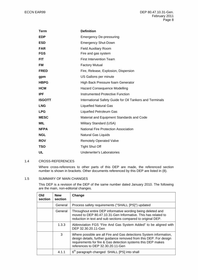
Term Definition
EDP Emergency De-pressuring
ESD Emergency Shut-Down
FAR FGS
Field Auxiliary Room Fire and gas system
FIT First Intervention Team
FM Factory Mutual
FRED Fire, Release, Explosion, Dispersion
gpm US Gallons per minute
HBPG High Back Pressure foam Generator
HCM Hazard Consequence Modelling
IPF Instrumented Protective Function
ISGOTT International Safety Guide for Oil Tankers and Terminals
LNG Liquefied Natural Gas
LPG Liquefied Petroleum Gas
MESC Material and Equipment Standards and Code
MIL Military Standard (USA)
NFPA National Fire Protection Association
NGL Natural Gas Liquids
ROV Remotely Operated Valve
TSO Tight Shut Off
UL Underwriter's Laboratories
1.4 CROSS-REFERENCES
Where cross-references to other parts of this DEP are made, the referenced section number is shown in brackets. Other documents referenced by this DEP are listed in (8).
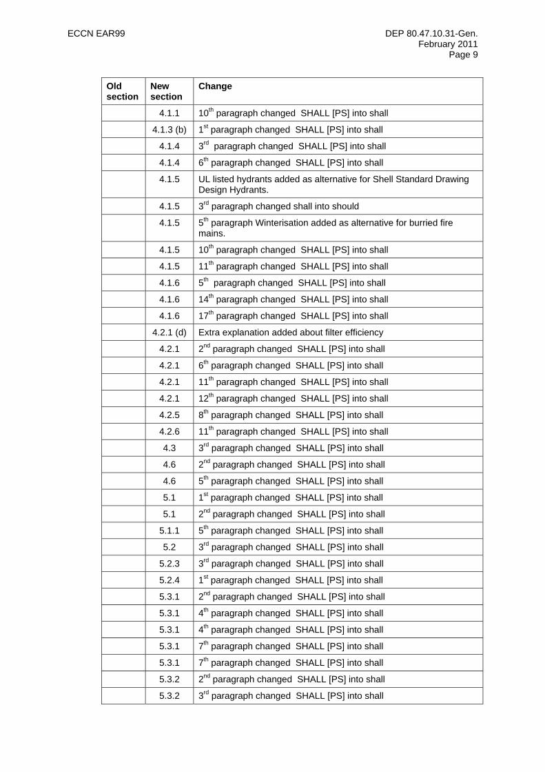
1.5 SUMMARY OF MAIN CHANGES
This DEP is a revision of the DEP of the same number dated January 2010. The following are the main, non-editorial changes.
Old section
New section
Change
General Process safety requirements ("SHALL [PS]") updated
General Throughout entire DEP informative wording being deleted and moved to DEP 80.47.10.31-Gen Informative. This has related to reduction in text and sub sections compared to original DEP.
1.3.3 Abbreviation FGS “Fire And Gas System Added” to be aligned with DEP 32.30.20.11-Gen
3 Where possible are all Fire and Gas detections System information, design details, further guidance removed from this DEP. For design requirements for fire & Gas detection systems this DEP makes references to DEP 32.30.20.11-Gen
4.1.1 6th paragraph changed SHALL [PS] into shall
ECCN EAR99 DEP 80.47.10.31-Gen. February 2011
Page 9
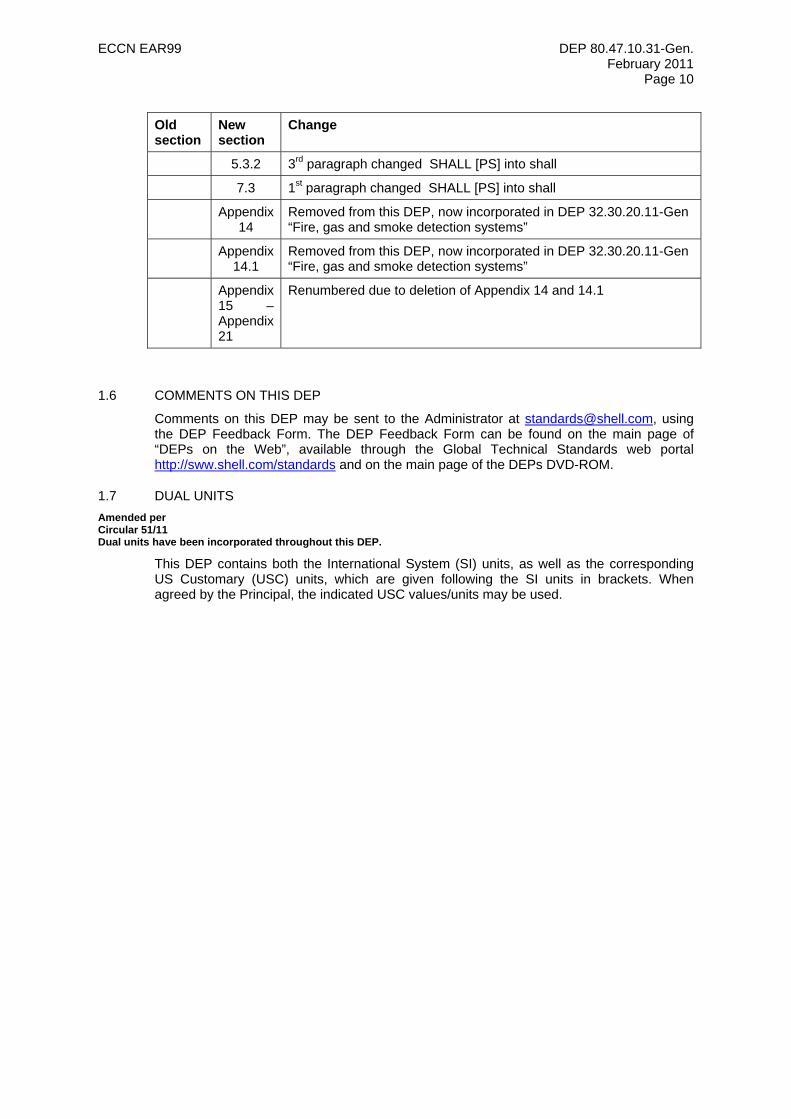
Old section
New section
Change
4.1.1 10th paragraph changed SHALL [PS] into shall
4.1.3 (b) 1st paragraph changed SHALL [PS] into shall
4.1.4 3rd paragraph changed SHALL [PS] into shall
4.1.4 6th paragraph changed SHALL [PS] into shall
4.1.5 UL listed hydrants added as alternative for Shell Standard Drawing Design Hydrants.
4.1.5 3rd paragraph changed shall into should
4.1.5 5th paragraph Winterisation added as alternative for burried fire mains.
4.1.5 10th paragraph changed SHALL [PS] into shall
4.1.5 11th paragraph changed SHALL [PS] into shall
4.1.6 5th paragraph changed SHALL [PS] into shall
4.1.6 14th paragraph changed SHALL [PS] into shall
4.1.6 17th paragraph changed SHALL [PS] into shall
4.2.1 (d) Extra explanation added about filter efficiency
4.2.1 2nd paragraph changed SHALL [PS] into shall
4.2.1 6th paragraph changed SHALL [PS] into shall
4.2.1 11th paragraph changed SHALL [PS] into shall
4.2.1 12th paragraph changed SHALL [PS] into shall
4.2.5 8th paragraph changed SHALL [PS] into shall
4.2.6 11th paragraph changed SHALL [PS] into shall
4.3 3rd paragraph changed SHALL [PS] into shall
4.6 2nd paragraph changed SHALL [PS] into shall
4.6 5th paragraph changed SHALL [PS] into shall
5.1 1st paragraph changed SHALL [PS] into shall
5.1 2nd paragraph changed SHALL [PS] into shall
5.1.1 5th paragraph changed SHALL [PS] into shall
5.2 3rd paragraph changed SHALL [PS] into shall
5.2.3 3rd paragraph changed SHALL [PS] into shall
5.2.4 1st paragraph changed SHALL [PS] into shall
5.3.1 2nd paragraph changed SHALL [PS] into shall
5.3.1 4th paragraph changed SHALL [PS] into shall
5.3.1 4th paragraph changed SHALL [PS] into shall
5.3.1 7th paragraph changed SHALL [PS] into shall
5.3.1 7th paragraph changed SHALL [PS] into shall
5.3.2 2nd paragraph changed SHALL [PS] into shall
5.3.2 3rd paragraph changed SHALL [PS] into shall
ECCN EAR99 DEP 80.47.10.31-Gen. February 2011
Page 10
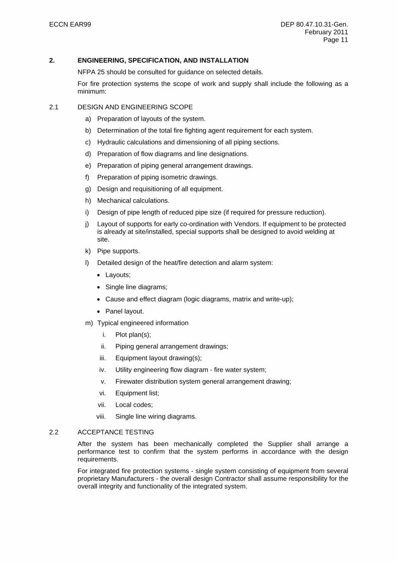
Old section
New section
Change
5.3.2 3rd paragraph changed SHALL [PS] into shall
7.3 1st paragraph changed SHALL [PS] into shall
Appendix 14
Removed from this DEP, now incorporated in DEP 32.30.20.11-Gen “Fire, gas and smoke detection systems”
Appendix 14.1
Removed from this DEP, now incorporated in DEP 32.30.20.11-Gen “Fire, gas and smoke detection systems”
Appendix 15 – Appendix 21
Renumbered due to deletion of Appendix 14 and 14.1
1.6 COMMENTS ON THIS DEP
Comments on this DEP may be sent to the Administrator at [email protected], using the DEP Feedback Form. The DEP Feedback Form can be found on the main page of “DEPs on the Web”, available through the Global Technical Standards web portal http://sww.shell.com/standards and on the main page of the DEPs DVD-ROM.
1.7 DUAL UNITS Amended per Circular 51/11 Dual units have been incorporated throughout this DEP.
This DEP contains both the International System (SI) units, as well as the corresponding US Customary (USC) units, which are given following the SI units in brackets. When agreed by the Principal, the indicated USC values/units may be used.
ECCN EAR99 DEP 80.47.10.31-Gen. February 2011
Page 11
2. ENGINEERING, SPECIFICATION, AND INSTALLATION
NFPA 25 should be consulted for guidance on selected details.
For fire protection systems the scope of work and supply shall include the following as a minimum:
2.1 DESIGN AND ENGINEERING SCOPE
a) Preparation of layouts of the system.
b) Determination of the total fire fighting agent requirement for each system.
c) Hydraulic calculations and dimensioning of all piping sections.
d) Preparation of flow diagrams and line designations.
e) Preparation of piping general arrangement drawings.
f) Preparation of piping isometric drawings.
g) Design and requisitioning of all equipment.
h) Mechanical calculations.
i) Design of pipe length of reduced pipe size (if required for pressure reduction).
j) Layout of supports for early co-ordination with Vendors. If equipment to be protected is already at site/installed, special supports shall be designed to avoid welding at site.
k) Pipe supports.
l) Detailed design of the heat/fire detection and alarm system:
• Layouts;
• Single line diagrams;
• Cause and effect diagram (logic diagrams, matrix and write-up);
• Panel layout.
m) Typical engineered information
i. Plot plan(s);
ii. Piping general arrangement drawings;
iii. Equipment layout drawing(s);
iv. Utility engineering flow diagram - fire water system;
v. Firewater distribution system general arrangement drawing;
vi. Equipment list;
vii. Local codes;
viii. Single line wiring diagrams.
2.2 ACCEPTANCE TESTING
After the system has been mechanically completed the Supplier shall arrange a performance test to confirm that the system performs in accordance with the design requirements.
For integrated fire protection systems - single system consisting of equipment from several proprietary Manufacturers - the overall design Contractor shall assume responsibility for the overall integrity and functionality of the integrated system.
ECCN EAR99 DEP 80.47.10.31-Gen. February 2011
Page 12
3. DETECTION
For Fire & Gas Detection systems (FGS) design reference is made to DEP 32.30.20.11-Gen Fire, gas and smoke detection systems.
4. WATER-BASED SYSTEMS
4.1 FIRE WATER DISTRIBUTION
Firewater distribution shall be designed such that firewater may be provided at the required flow rate in all plant sections under all credible circumstances. Non-availability of a section of the firewater distribution main shall normally not affect the firewater availability elsewhere in the plant. Distribution systems should be provided with block valves such that sections may be isolated for maintenance.
4.1.1 Storage
(a) General
The fire safety assessment shall determine the storage capacity and sparing philosophy based on the largest credible fire scenario in the installation.
If an uninterrupted supply of firewater from open water, wells, or a third party fire main cannot be guaranteed at the maximum required water flow rate, pressure and duration, a dedicated firewater storage facility SHALL [PS] be provided. In order to allow inspection and maintenance of water storage facilities, the n+1 principle shall be applied for providing temporary or alternate storage (e.g., cooling water basin, additional tank).
Dedicated fire water storage facilities shall be located off plot in an area, normally within the property fence, and SHALL [PS] be located at least 50 m away from fire areas or according to results of HCM in a safe area away from fire hazard area
(b) Design
Firewater storage facilities may be of the closed or open storage type. The choice is determined by economic and local conditions (e.g. available land area and sub-soil conditions).
(i) Closed storage
Metallic fixed roof tanks are normally more cost-effective than closed non-metallic or concrete tanks. Depending on the selected type, closed metallic storage facilities shall be in accordance with:
• DEP 34.00.01.30-Gen. and,
• DEP 34.11.00.11-Gen. and
• DEP 34.28.00.31-Gen. and
• DEP 34.51.01.31-Gen. or DEP 34.51.01.33-Gen
(ii) Open storage
Three types of open storage may be used: membrane-lined earthen bund wall basin (refer to Appendix 1), concrete basin, and metallic tank. Adequate fencing/railing and appropriate life saving equipment shall be provided.
Basins shall be in accordance with:
• DEP 34.00.01.30-Gen. and
• DEP 34.11.00.11-Gen. and
• DEP 30.10.02.13-Gen.
Open metallic tanks shall be built in accordance with 4.1.1 (b) (i).
ECCN EAR99 DEP 80.47.10.31-Gen. February 2011
Page 13
A level instrument shall be installed to give a low level alarm in the main control room at 80% of the maximum filling level. At maximum filling level an overflow shall be provided.
Provisions should be considered for injecting water treatment chemicals to control the growth of algae or bacteria like legionella.
The design, particularly of open type storage facilities, shall cater for possible evaporation losses.
The discharge connection(s) on the storage facilities (e.g., suction to fire pumps, replenishment system) shall include easy-to-clean strainers.
In climates where freezing may occur, provisions SHALL [PS] be made to prevent the water becoming frozen. Such provisions should include a combination of circulation, heating and increased storage capacity to compensate for an ice layer of specified maximum thickness.
4.1.2 Pumps and Drivers
(a) General
The fire safety assessment shall determine the pump sparing (i.e., main pump(s) back-up) philosophy (applying the n + 1 principle), the selection of drivers for the pumps, and the maximum flow rate. The avoidance of common mode failures (e.g., fire in the fire water pump house) shall be addressed in the design.
Firewater shall therefore be provided by at least two pumps, each of which is able to supply the largest required flow rate to the firewater distribution system. An alternative with a higher reliability is the installation of three identical pumps, each able to supply 60% of the largest required flow rate.
The selection of the pump drivers is governed by the requirement of maximum reliability of the overall system. This is directly related to the reliability of the associated utility system (power, steam ad fuel supply) and the instrumentation system.
Pumps, drivers, and appurtenances shall be designed and installed in accordance with DEP 31.29.02.11 -Gen. NFPA 20 may be used as guidance unless full compliance to NFPA 20 is required by local authorities.
Where fixed pumps are not justified or practicable from fire assessment, consideration may be given to the use of mobile, containerised or modular pumps and the above considerations regarding reliability and availability shall still apply. Refer to DEP 80.47.10.32-Gen.
Firewater pumps SHALL [PS] be installed in a location that is considered to be safe from the effects of fire and clouds of flammable vapour, and from collision damage by vehicles and shipping. The pumps should be located as close as possible to the firewater storage or alternative water source. Sprinkler systems or deluge systems may be considered for the protection of enclosed pump houses. Heat detection should be considered if detection is required.
(b) Pump Design
The firewater pumps rated pressure shall be based on a minimum pressure of 10 barg at the furthest take-off point on the distribution system, with the highest water flow demand. Individual pump design capacity should not exceed 1000 m3/h (4400 gpm) unless suitable pump handling and maintenance facilities are available. If the required pump capacity exceeds 1000 m3/h (4400 gpm), two or more smaller pumps shall be installed, subject to the n + 1 principle.
Firewater pumps shall be of the submerged vertical type if draining from open water, and of the horizontal, between bearings, type if draining from a storage tank.
If a jockey pump is used to keep the distribution system pressurised, it shall be backed up by a spare (installed) jockey pump; each jockey pump shall have a typical capacity of 15 m3/h (66 gpm) to compensate for leakage. If the jockey pumps are also to be used for providing plant service water, then they shall have a larger capacity that need to be specified by the Principal. If there are significant (e.g., excess of 10 m
ECCN EAR99 DEP 80.47.10.31-Gen. February 2011
Page 14
[33 ft]) differences in elevation of sections of the distribution system, the jockey pump and control system shall ensure sections are not left dry or subject to excessive pressures.
(c) Pump Suction and Discharge Piping
Each pump suction should be provided with an easy-to-clean inlet screen with a local differential pressure indication. If individual pump inlet strainers are difficult to maintain, then each pump discharge line shall be equipped with a strainer having a flushing facility. Each pump discharge line shall be fitted with a check valve, pressure gauge and isolation valve. Provisions shall be made to test each pump individually; the test valves shall have a common return line with a flow metering point.
Each pump shall be connected separately to a common manifold (see Appendix 2). The common discharge manifold should be connected to the fire water distribution system by two separate lines, each of the same size as the distribution piping and each equipped with a block valve.
Piping shall comply with DEP 31.38.01.11-Gen.
(d) Driver
The power rating for all the drivers shall be such that it is possible to start each pump against a closed discharge valve with a fire mains pressure ranging between 2 barg (29 psig) and 16 barg (230 psig).
If only electrical firewater pumps are installed, or if electric power is required to start and control diesel-driven firewater pumps, electrical power SHALL [PS] be from the essential supply system (refer to DEP 33.64.10.10-Gen.).
Diesel drivers shall be installed and field inspected in accordance with DEP 31.29.00.10-Gen. and DEP 61.10.08.11-Gen. Diesel storage vessels (fuel tank) shall be constructed in accordance with DEP 30.10.02.11-Gen and NFPA 20. A clutch shall not be installed between a diesel driver and a firewater pump.
(e) Housing
Pumps shall be accessible to facilitate maintenance, and be provided with hoisting facilities in accordance with the requirements of DEP 31.25.00.10-Gen. In locations where freezing can occur, the fire water pumps shall be installed in a heated housing for protection; for other locations, only a rain/sun cover may be required.
4.1.3 Pressure Control
For normally manned installations the firewater pumps shall always be started manually. Manual starting of each firewater pump shall be possible at the pump, from the control centre and, if necessary, from the emergency centre. Manual stopping of each pump unit shall only be possible at the pump.
The control scheme shall be designed in accordance with Appendix 2, so that should the main firewater pump(s) fail to start manually or, having started, fail to build up the required pressure in the firewater distribution system within twenty seconds, the firewater pump(s) designated as the spare or back up shall automatically start.
(a) Normal (Stand-by) Operating Condition
During normal operation, the main fire water pump(s) shall be in the stand-by mode, with either the jockey pump(s) or other pressure source (e.g., static height, cooling water system) maintaining a minimum pressure of 2 barg (29 psig) in the fire water distribution system. In this condition, the pump discharge control valve 100 PCV-101A or 100 PCV-101B (air failure open) is at the minimal stop, while the dump valve 100 PCV-101C (air failure open) is in the closed position.
The Principal may decide that other normal (stand-by) operating conditions are required.
(b) Fire Operating Condition
ECCN EAR99 DEP 80.47.10.31-Gen. February 2011
Page 15
When the main firewater pump or the “first main fire water pump” (if more than one main fire water pump is required according to section 4.1.2 (a)) is manually started, 100 PCV-101C shall fully open. To prevent a pressure surge in the main fire water system, the main firewater pump shall only be allowed to start when 100 PCV-101C has reached its fully open position.
If the distribution system pressure does not reach 5.5 barg (80 psig) within twenty seconds after starting of the first main fire water pump, another pulse shall be sent to start the fire water pump designated as the spare or back-up. Thirty seconds (i.e., the time necessary for the valve to open) after the main firewater pump was manually started, controller 100 PIC-101 shall throttle control valves 100 PCV-101A or 100 PVC-101B, and 100 PCV-101C as required maintaining the firewater distribution system pressure at 6 barg (90 psig) to 7 barg (100 psig) This initial set pressure of 6 barg to 7 barg (100 psig) is chosen for personal safety reasons (i.e. for hose handlers and/or other firewater users at the time of pressure increase).
In the central control room, a facility (100 HIC-101) shall be provided to adjust the firewater distribution system pressure. While normally set at 6 barg (90 psig) to 7 barg (100 psig) as noted above, the pressure control system shall be designed allow a manual increase of the fire water distribution system pressure to a maximum of 10 barg unless a higher maximum set pressure is required from a fire fighting point of view to be able to supply firewater at sufficient pressure to specific locations. This higher set pressure shall only to be allowed up to a maximum of 12 barg (175 psig), and only after validation of all components of the fire main system, and only with the approval of the Principal.
The Principal may decide that other fire operating conditions are required.
4.1.4 Pipe and Valves
(a) Pipe or “Ring Mains”
The distribution system shall consist of “ring mains” as detailed in Appendix 3, installed to reach (surround) all processing units, storage facilities for flammable liquids, loading/unloading facilities for road vehicles and rail cars, gas bottle-filling plants, warehouses, workshops, utilities, training grounds, laboratories and offices. The system shall be installed at close proximity to access facilities where fire-fighting equipment can be hooked up. A single firewater line is acceptable for jetties and fire-fighting training ground.
The distribution system design shall provide for a maximum allowable velocity in the firewater piping of 3.5 m/s (11.5 ft/s) to prevent surging at these conditions. The pipe sizes shall be calculated based on design flow rates at a pressure of 10 barg (150 psig) at the take-off points of each appropriate section even if one of the supply sides has been blocked or is out of operation. A check calculation shall be made to prove that pressure drop is acceptable with a blocked section of piping in the system. A surge analysis of the firewater distribution system shall be performed and, where required, surge protection devices SHALL [PS] be provided.
A full bore flushing connection shall be provided in the fire water distribution system if the fire-water quality could result in settlement of silt in the piping, if marine growth is likely, or in cases where corrosion (rust flakes) or erosion (cement particles) products may be formed. The full bore valved flushing connections shall be located so that all sections and dead ends can be properly flushed out. The flushing connections shall be sized for a fluid velocity in the relevant piping of not less than 80% of the velocity under normal design conditions, with a minimum of 2 m/s (6.5 ft/s).
The firewater distribution system components SHALL [PS] be installed underground if located within the 0.15 bar (2.18 psi) over-pressure contour corresponding with an exceedance frequency of 1E-4/yr in plant areas where explosions cannot be excluded unless materials are used that will survive the maximum design explosion overpressure loads. The firewater distribution system components SHALL [PS] be installed underground or alternative winterisation measures are to be installed where
ECCN EAR99 DEP 80.47.10.31-Gen. February 2011
Page 16
the ambient temperature can drop below 0ºC (32ºF) for prolonged periods. When installed underground, placement shall be in accordance with DEP 31.38.01.11-Gen and materials of construction should be glass-fibre reinforced plastic (GRP) in accordance with DEP 31.40.10.19-Gen for underground piping. Other materials such as HDPE, lined steel may be used if approved by the Principal
When the firewater distribution system is installed above ground, it shall not be laid in pipe tracks at risk from potential spill fires. In addition, appropriate protection from potential physical damage shall be provided in areas where impact is likely. The material selection for aboveground piping shall be based on the predominant firewater quality.
(b) Valves
Standard (Full) bore isolation valves shall be incorporated in the firewater distribution system so that sections can be isolated for maintenance, etc. These sections shall be selected so that the required quantity of water can still be supplied from other hydrants with fire hoses having a maximum length of 100 m. For fire fighting systems, piping classes 11201 (carbon steel), 17101 and 17120 (GRE), 18011 and 18101 (galvanized carbon steel) are available (see DEP 31.38.01.12-Gen.). The block valves, included in these R&C piping classes, shall be gate valves or butterfly valves and selected as defined in the applicable MESC buying descriptions. Valves should be approved, where practicable, to UL 262 and UL 1091 or in compliance with MESC specifications related to the piping classes for firewater service. When valves are installed in an underground system, it shall be possible to observe whether the valves are in the open or closed position. This shall be indicated by the rising spindles of the valves, or by valves fitted with position indicators.
At the foot of a jetty, manually operated isolation valves shall be provided between the firewater distribution system and the firewater piping on the jetty. The objective is to save the integrity of the firewater distribution system in the event of serious damage to the jetty.
4.1.5 Hydrants
In order to be able to take water from the firewater distribution system at the required location, permanent hydrants shall be installed.
(a) Location
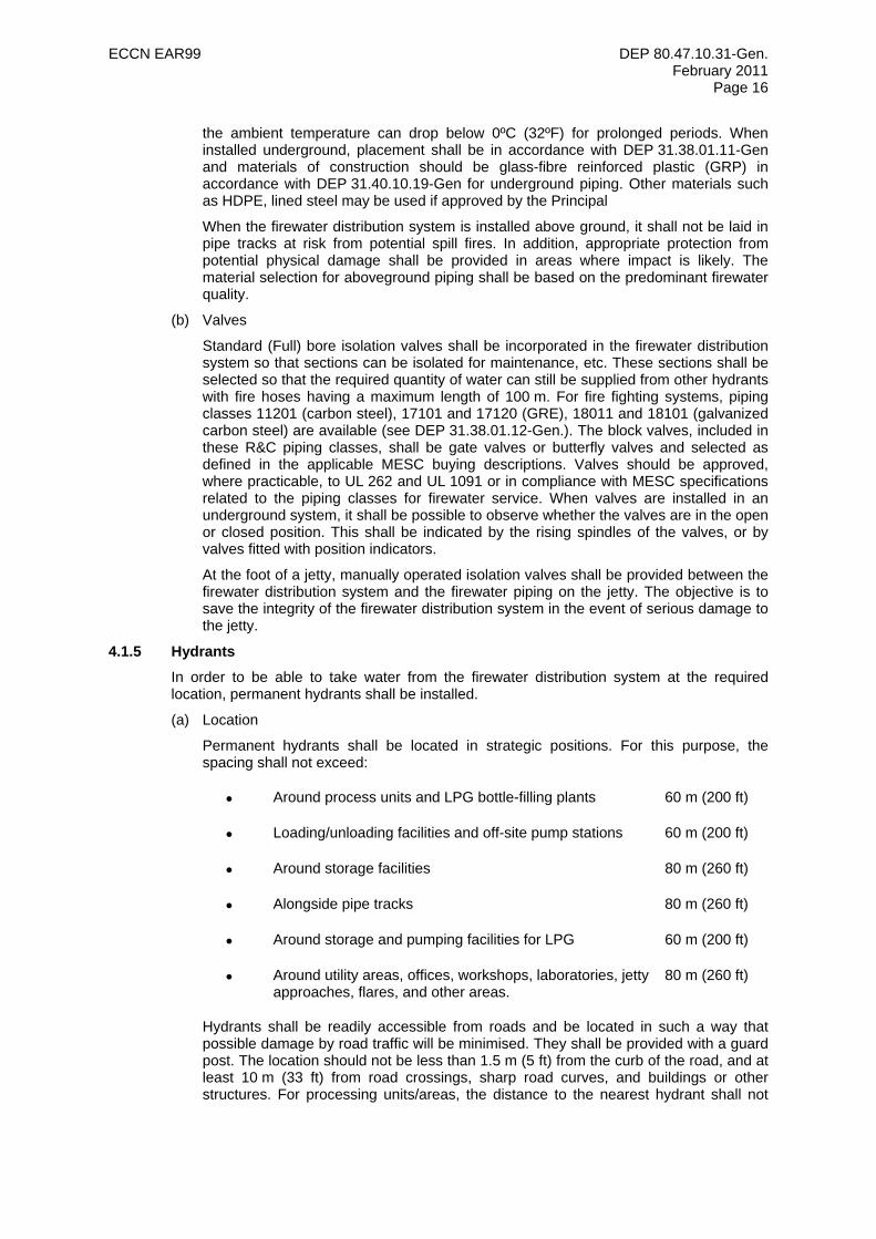
Permanent hydrants shall be located in strategic positions. For this purpose, the spacing shall not exceed:
• Around process units and LPG bottle-filling plants 60 m (200 ft)
• Loading/unloading facilities and off-site pump stations 60 m (200 ft)
• Around storage facilities 80 m (260 ft)
• Alongside pipe tracks 80 m (260 ft)
• Around storage and pumping facilities for LPG 60 m (200 ft)
• Around utility areas, offices, workshops, laboratories, jetty approaches, flares, and other areas.
80 m (260 ft)
Hydrants shall be readily accessible from roads and be located in such a way that possible damage by road traffic will be minimised. They shall be provided with a guard post. The location should not be less than 1.5 m (5 ft) from the curb of the road, and at least 10 m (33 ft) from road crossings, sharp road curves, and buildings or other structures. For processing units/areas, the distance to the nearest hydrant shall not
ECCN EAR99 DEP 80.47.10.31-Gen. February 2011
Page 17
exceed 50 metres (165 ft). Each hydrant should be provided with a hard-paved grade (e.g., concrete, asphalt, packed dirt).
Hydrants shall be compatible, wherever practicable, with equipment specified for use by site first intervention team and fire brigade or in use amongst local authority/municipal fire response groups and mutual aid organisations.
(b) Selection
Hydrants each with four outlets shall be provided for in:
• Processing units/areas;
• Loading/unloading facilities;
• LPG bottle filling plants;
• Storage facilities for flammable liquids and LPG;
• Off-site pump stations;
• Jetty heads/berths.
Hydrants with minimum two outlets shall be installed around all other areas, such as:
• Jetty approaches; (if needed)
• Warehouses;
• Workshops;
• Laboratories;
• Offices;
• Utilities.
All hydrants in and around a process plant shall be of the type suitable to mount stationary monitors (see section 4.1.6). This shall also be considered for other specific locations as directed by the fire safety assessment.
The fire safety assessment shall identify if hydrants are to be equipped with a large bore firewater truck connection above the number of outlets specified above.
(c) Design
Each outlet branch shall have a DN 80 (NPS 3), ASME class 150, flat-faced flange, for accommodating a 65 mm (2½ in) hydrant valve. The valve shall be of the angle type, with an angle of 45° between inlet and discharge, suitable for a working pressure of 16 barg (230 psig). The valve outlet shall be provided with a 65 mm (2½ in) coupling in accordance with local standards. The coupling shall point downwards and be fitted with a chained cap. Valves and the valve components shall be as specified in MESC 96.25.10. Recommended coupling types are Storz (which is preferred) and instantaneous - female connection. Alternative types subject to approval by the Principal could be used to give locations flexibility of using similar connections to hydrants that they already have.
Hydrants may need a large bore outlet branch for feeding fire trucks. In areas where large volume fire fighting scenarios may exist, such as storage tank areas, hydrants may need large bore outlet branch(es) allowing high volume water transport. The size and number of high volume outlet branches shall be specified by the Principal.
For expansion of existing installations, or for new construction projects in the neighbourhood of existing installations, couplings shall be of the same type as already applied in these installations. Couplings should also be compatible with the type used by the local fire brigades.
Where freezing can occur, hydrants shall have an automatic bottom drain valve unless local circumstances and or local authorities require other arrangements. The drain
ECCN EAR99 DEP 80.47.10.31-Gen. February 2011
Page 18
valves shall have drain holes of minimum size 8 mm (0.31 in) and total free area of at least 200 mm2 (0.31 in2). The drains shall be located so that checking for blockage and maintenance is facilitated. The drain openings shall automatically close when the hydrant isolation valve is being opened.
Hydrants shall be in accordance with one of the following Standard Drawings unless otherwise specified by the principal. The minimum alternative design requirements shall use UL listed hydrants.
GRE underground mains
Freezing area S 88.012
Non-freezing area S 88.013
Hydrant header construction shall be in accordance with one of the following Standard Drawings unless otherwise specified by the principal. The minimum alternative design for hydrants shall be UL listed:
Four-way hydrant header S 88.017
Four-way hydrant header, with monitor connection S 88.018
Two-way hydrant header S 88.016
(d) Material specification
Hydrants shall be made from carbon steel; for salt/brackish water internally coated carbon steel pipe shall be used in accordance with DEP 31.38.01.12-Gen.
4.1.6 Stationary monitors
(a) General
The fire safety assessment shall determine the location, the capacity, the area to be covered, the method of operation (i.e., manual or remote-control powered) and the type (i.e., ground level or elevated) of stationary firewater monitors. For general protection purposes, the preferred arrangement is fixed manually operated monitors with adjustable nozzles installed at strategic points around and inside plant areas where fire hazards have been identified. Generally, self-oscillating monitors are not recommended due to their unreliability. The spacing (for a standard 2000 L/min [530 gpm] monitor) should be based on a 50 m (165 ft), 360o water projection with no blockage from adjacent equipment to the fire hazard area.
Where practical, stationary monitors may be installed on firewater hydrants (see 4.1.5). This reduces the number of tie-inn connections to the fire main.
Elevated stationary firewater monitors may be needed to protect congested areas and where obstructions (e.g., at table tops and at jetty heads) prevent the effective use of ground level monitors. Locally controlled elevated monitors can be provided with cable, chain or gear mechanisms to adjust elevation, rotation and nozzle setting. Remotely controlled elevated monitors, when installed, should have a rotation and elevation speed of approximately six degrees/second.
In salt/brackish firewater service or in freeze areas, monitors shall be provided with a connection to drain and flush the normally dry parts of the monitor after testing or use.
(b) Design
Upstream of the mounting flange each monitor shall be provided with a butterfly valve or another type of valve specified by the Principal accessible from grade. For elevated monitors the valve shall be operable from grade and in case an additional valve is installed at the elevated monitor this valve shall be locked or car-sealed open.
ECCN EAR99 DEP 80.47.10.31-Gen. February 2011
Page 19
The inlet mounting flange connection shall be ANSI/ASME B 16.5, 150 lbs., Raised Face (RF), DN 100 (NPS 4) for a standard 2000L/min [530 gal/min] monitor. Higher capacity monitors might require larger diameter inlet flanges. .
The typical monitor should have a 65 mm (2 ½ in) threaded connection and be equipped with a constant flow, adjustable stream (i.e., fog to jet) nozzle.
Unless determined differently from the fire safety assessment, the monitors shall be 2000 L/min [530 gal/min] capacity at a working pressure of 10 barg (150 psig). The maximum operating pressure shall be 16 barg (230 psig). At 7 barg (100 psig) inlet pressure, the fire water jet stream at 30° elevation should reach 50 m (165 ft) and have a footprint of 4 m x 6 m (13 ft x 20 ft) with 80 % of the total water flow reaching the footprint. At the same inlet pressure [7 barg] (100 psig) water fog stream at 30° elevation and 30° nozzle position shall reach 18 m and have a footprint of 7 m x 8 m (23 ft x 26 ft) with 80 % of the total water flow reaching the footprint.
The monitor shall have a horizontal traverse of 360° and a vertical elevation of 15° below to 85° above horizontal. For elevated monitors these figures may be replaced by respectively 75° and 45°. Monitors shall be provided with the ability to lock the traverse and elevation in any chosen position.
All moving parts shall be fully protected / enclosed against ice and dirt.
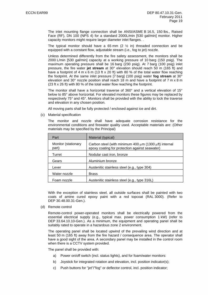
(c) Material specification
The monitor and nozzle shall have adequate corrosion resistance for the environmental conditions and firewater quality used. Acceptable materials are: (Other materials may be specified by the Principal)
Part Material (typical)
Monitor (stationary part)
Carbon steel (with minimum 400 µm (1300 µft) internal epoxy coating for protection against seawater)
Turret Nodular cast iron, bronze
Gears Aluminium bronze
Lever Austenitic stainless steel (e.g., type 304)
Water nozzle Brass
Foam nozzle Austenitic stainless steel (e.g., type 316L)
With the exception of stainless steel, all outside surfaces shall be painted with two coats of amine cured epoxy paint with a red topcoat (RAL 3000). (Refer to DEP 30.48.00.31-Gen.).
(d) Remote control
Remote-control power-operated monitors shall be electrically powered from the essential electrical supply (e.g., typical max. power consumption 1 kW) (refer to DEP 33.64.10.10-Gen.). As a minimum, the equipment and operating panel shall be suitably rated to operate in a hazardous zone 2 environment.
The operating panel shall be located upwind of the prevailing wind direction and at least 50 m (165 ft) away from the fire hazard / consequence area. The operator shall have a good sight of the area. A secondary panel may be installed in the control room when there is a CCTV system provided.
The panel shall be provided with:
a) Power on/off switch (incl. status lights), and for foam/water monitors:
b) Joystick for integrated rotation and elevation, incl. position indicator(s);
c) Push buttons for "jet"/"fog" or deflector control, incl. position indicator;
ECCN EAR99 DEP 80.47.10.31-Gen. February 2011
Page 20
d) Switch for opening water supply valve, incl. "open/closed" position indicator;
e) Switch for opening the foam solution inlet valve, incl. "open/closed" position indicator;
f) Reset (stop) button;
g) Individual failure alarm indication for rotation, elevation and jet/fog control motors;
h) Maintenance override.
Where electrical and instrumentation cables run through the fire area they shall be protected against the effect of such a fire. This can be achieved by running them underground, by using fire resistant cables, or by enclosing them in fire resistant cable ducting.
4.1.7 Dry Risers
The fire safety assessment shall determine the need and location of dry riser installations. When specified, the riser shall be installed in or adjacent to the stairway (e.g., main, alternate, and emergency access routes). At the ground floor level of the riser(s), a two-way flapper valve ("collecting breeching") shall be permanently installed. On each floor above (and below) the ground floor, two connections should be provided, each having a hydrant valve and hose connections as detailed in (4.1.7) located 0.7 m (2 ft) above the floor. An automatic vent shall be installed at the riser(s) highest point.
Dry risers should be made from flanged carbon steel pipe to be hot-dip galvanised after fabrication or another non-corrosive material specified by the Principal.
4.2 FIRE WATER SPRAY SYSTEMS
4.2.1 General
The fire safety assessment shall determine which equipment is to be protected by a water spray system, the method of protection, and the amount of protection. All spray system shall be provided with local operation. Depending on the fire risks, spray systems may also be provided with remote (e.g., control room) operation.
(a) Hydraulics
The design of a water spray system shall be based on hydraulic calculations to determine the required pressures and corresponding water quantities of the spray nozzles. The calculations shall be submitted to the Principal for approval.
The normal working pressure shall be established at the point of off-take under conditions of maximum water consumption, i.e. for the fire case. The pressure should be at least 10 barg (150 psig). Pressure spikes/surges may occur during initial admission of water into a "dry" section of water spray systems. The magnitude of such pressure spikes/surges shall be investigated and, if critical, special measures shall be taken (e.g. excess flow control, etc.).
The systems shall be designed in such a way that the required pressure for the best operation of the spray nozzles is achieved by adequate dimensioning of the piping without the use of restriction orifices. The on-off control valve, filter etc. shall be factored into the calculation. If there is still a pressure reduction required, a calculated length (max. 2 m [6.5 ft]) of small-bore piping shall be installed downstream of the on-off control valve and the manually operated block valve. The spool material should be Monel 400, flanged and having a minimum size of DN15 (NPS ½).
In all cases a detailed layout shall be made of the equipment and areas to be protected on which the arrangement of the spray nozzles shall be shown. For this purpose the plant's piping model shall be used. Alternatively, in exceptional cases, the relevant piping general arrangement drawing may be used.
(b) Connection to distribution system
ECCN EAR99 DEP 80.47.10.31-Gen. February 2011
Page 21
A water spray system shall have two separate connections to two different sections of the firewater distribution system. In case of remote operation one of the connections shall be equipped with an on-off control valve (see section (e) below); the other connection shall be a standard manually operated valve. Both valves shall, if possible, be installed upwind of the prevailing wind direction. The on-off control valve shall be at least 15 m (50 ft) from the water spray system. The manual valve shall be safely accessible under the prevailing fire scenario, and should typically be located 30 m (100 ft) away from the spray system. At both connections, a filter (see (d) below) shall be provided (i.e., a shared filter or one per connection).
Piping shall be flanged for all sizes. Where salt/brackish water is used, the flanged cross-over piping from underground to above ground and piping to the on-off control valve and manually operated valve, shall be internally coated; preferably by epoxy paint (minimum 400 µm [1300 µft] dry film thickness) or alternatively by cement lining.
In locations susceptible to freezing, electrical trace heating shall be considered. If the fire safety assessment indicates that heat tracing is required, it shall be applied in accordance with DEP 33.68.30.32-Gen.
(c) Spray system piping
Horizontal "dry" piping, downstream of the on-off control valve and the manually operated valve, shall be installed with a slope of 1:200 or steeper. At a minimum, low point drains on the piping, weep-holes on the spray headers, and automatic drain valves at selected locations on the system shall be provided. Where the fire water quality necessitates frequent flushing and cleaning of the spray system, a DN 80 (NPS 3) branch with valve and DN 65 (NPS 2 ½) hose coupling shall be provided at each fire water supply side (downstream of the on-off control valve and the manually operated valve).
All overhead piping should be well supported and fixed to prevent deflection and vibrations. When supported from grade, the supports shall be fireproofed if structural redundancy cannot be incorporated to withstand fire exposure.
Piping shall be galvanised, in accordance with DEP 31.38.01.12-Gen. piping class 18011. In exceptional cases where it is envisaged that the orientation of the water spray nozzles will require adjustment after installation, screwed double elbows may be provided.
(d) Filter
Filters shall be of a bucket-type design, with a retractable insert. Each filter shall have a minimum capacity of 800% of the nominal inlet-piping diameter.
The filter openings shall be at least 50% of the size of the smallest spray nozzle orifice opening to be used, with a maximum of 4 mm (0.16 in) diameter.
The filter housing shall be carbon steel; for use in salt/brackish water it shall be internally epoxy coated (min. 400 µm [1300 µft]). Filter element material to be stainless steel (316L) or Monel 400.
(e) Valves
The on-off control valve or manually operated valve shall be an UL-1091 listed butterfly valve or in compliance with MESC specifications related to piping classes for firewater service. The valve shall be tight shut off (TSO: Class V or VI according to IEC 60534-4) in the forward direction against a maximum pressure of 16 barg (230 psig). The control valve shall fully open within 10 seconds. Refer to DEP 32.36.01.17-Gen. for control valves and DEP 31.37.00.11-Gen. for instrument air requirements.
(f) Spray nozzles
Medium velocity, full cone, open-type spray nozzles with external deflectors shall be fitted. Internal strainers are not permitted as they can block the nozzle during operation. Recommended operating range is between 2 barg (30 psig) and 3.5 barg (50 psig). The orifice diameter of the nozzles shall not be smaller than 8 mm (0.31 in).
ECCN EAR99 DEP 80.47.10.31-Gen. February 2011
Page 22
The nozzles shall be provided with a male threaded connection; min. size DN 15 (NPS ½). Nozzle material should be stainless steel (316) or Monel 400.
The water spray nozzle Manufacturer shall provide full test data on the nozzle, i.e.:
• Spray pattern at applicable distance;
• Flow rate at applicable pressure;
• Distribution rate over the area.
4.2.2 Pump and compressor protection
If the fire safety assessment determines that a pump or compressor shall be protected by a spray system, it shall be designed and installed in accordance with this section and as depicted in Appendices 4 and 6. A maximum of four pumps should be protected by a single spray system. NOTES: 1. The 2.5-3 m (8-10 ft) elevation shown in Appendix 6 is typical; the actual elevation shall be
selected so that the spray pattern completely envelopes the pump.
2. The number of spray nozzles shall be at least two. More nozzles (up to a maximum of four) may be necessary for larger pumps to achieve the water densities shown in Appendix 6.
3. If a group of pumps (e.g., congested area) is to be protected by a spray system, the spray nozzles shall be spaced in a regular manner; however, the overlapping spray pattern from two adjacent nozzles shall cover the pump body.
4.2.3 Horizontal vessel and heat exchanger protection
If the fire safety assessment determines that a horizontal vessel or heat exchanger shall be protected by a spray system, it shall be designed and installed in accordance with this section and as depicted in Appendix 4.
Spray water nozzles shall be directed radially to the vessel/heat exchanger wall and heads. If spray patterns are obstructed by platforms, stairs, flanges, manholes etc., additional spray nozzles shall be provided to achieve complete coverage. The water spray system shall be arranged so as not to interfere with the future maintenance requirements of the equipment.
The spray nozzles shall be installed at a distance not exceeding 0.6 m (2 ft) from the equipment surface. Only one type and size of spray nozzle shall be fitted. See Appendix 7.
Spray nozzles shall be fitted to the upper part of horizontal piping to minimize the change of blockage.
4.2.4 Column and vertical vessel protection
If the fire safety assessment determines that a column or vertical vessel shall be protected by a spray system, it shall be designed and installed in accordance with this section and as depicted in Appendix 4. Fireproofed skirts do not require protection by the water spray system.
The arrangement of water spray nozzles shall be such that complete coverage of shell and heads (including appurtenances) is obtained, with minimum loss due to wind and up draught. For this purpose spray water nozzles shall be directed radially to the column/vessel wall and heads. The number of spray nozzles on each level and the spray angle (inclination) of the nozzles depend on the column/vessel diameter. If spray patterns are obstructed by platforms, stairs, flanges, manholes etc., additional spray nozzles shall be provided to achieve complete coverage. The water spray system shall be arranged so as not to interfere with the future maintenance requirements of the equipment.
The spray nozzles shall be installed at a distance not exceeding 0.6 m (2 ft) from the equipment/insulation surface. Only one type and size of spray nozzles shall be fitted (see Appendix 8).
Spray nozzles shall be fitted to the upper part of horizontal piping to minimize the change of blockage.
ECCN EAR99 DEP 80.47.10.31-Gen. February 2011
Page 23
4.2.5 Spherical tank protection
If the fire safety assessment determines that a spherical tank shall be protected by a full coverage spray system, it shall be designed and installed in accordance with this section and as depicted in Appendix 4. Other more robust and cost effective options such as water drenching, partial coverage, and use of stationary firewater monitors shall be addressed in the fire safety assessment. (If stationary monitors are considered, range should be sufficient to provide adequate coverage of the vessel under typical wind conditions).
Spray nozzle arrangements shall be as detailed in Appendix 9 and 10. If the water demand to the sphere spray system is the largest in the facility and more than the "standard" pump rating required for other credible scenarios, the fire safety assessment shall also determine whether further sectionalising of the upper and lower sections of the system may be required. Complete wetting of the entire sphere surface is required independent of rundown. Because of overlap in the spray pattern, spraying of the appurtenances and selection of the next larger spray nozzle, the actual rate is very likely already higher than the required water application rate.
To economise on water consumption, the sphere may have its spray system split into two entirely separate sections, one for the upper and one for the lower half of the sphere. As well as the sphere surface itself, all appurtenances, non-fire proofed sections of the supporting legs and equipment in the containment area shall be water sprayed. Nozzles shall be installed on a single ring header at the upper part of the sphere. For easy access and maintenance this ring header shall be installed near the top platform. The number of headers plus spray nozzles and the capacity thereof shall be such that the upper half of the sphere is covered with the required application rate as described above. The sphere surface area above the ring header elevation, as well as the appurtenances like safety valves and instrumentation located at the top of the sphere, shall be adequately wetted, possibly by installing additional dedicated spray nozzles located above such equipment.
The lower half of the sphere shall be protected by water spray from nozzles installed at regular intervals to achieve complete coverage (wetting) with overlapping spray patterns. The preferred method is to use a "top" ring header feeding regularly spaced legs in the vertical plane, concentric to the sphere surface.
Spray water nozzles shall be directed radially at the sphere surface. The spray nozzles shall be installed at a distance not exceeding 0.6 m (2 ft) from the equipment surface.
The filling/outlet line shall also be protected by water spray up to the isolating valve, located outside the containment wall.
The sphere's support legs will typically be provided with fire proofing material, able to withstand heat for a limited time period. To protect against prolonged heat input, the legs may also require water spray protection. Here particular attention shall be paid to the region where the support leg meets the sphere. HCM may be required to determine fire duration for credible incident(s) and to evaluate the requirement for additional water spray protection.
Where supports, stairs, platforms, nozzles, manholes etc. interfere with the spray patterns or the rundown water layer, additional spray nozzles shall be provided to guarantee complete coverage. This may also be achieved via fixed firewater monitors that can reach the area that requires additional protection. Sufficient allowances shall be made to compensate for water loss due to wind, overshooting etc.
Ring headers shall be constructed from circular or straight pre-fabricated pipe sections. The upper half and lower half "top" ring header shall be firmly supported from the top platform and the sphere's support legs respectively. The vertical legs of the lower part shall be provided with distance pieces (no welding on sphere) and pulled together at their free ends.
4.2.6 Storage Tank protection
If the fire safety assessment determines that a storage tank shall be protected by a water spray system, it shall be designed and installed in accordance with this section and as depicted in Appendix 4.
ECCN EAR99 DEP 80.47.10.31-Gen. February 2011
Page 24
Spray nozzle arrangements shall be as detailed in Appendices 11, 12 and 13. Typically, the entire roof outer surface (exception: external floating roof) and the external wall shall be sprayed. If the water demand to the storage tank spray system is the largest in the facility and more than the "standard" pump rating required for other credible scenarios, the fire safety assessment shall also determine whether the spray system will have to be sectionalised.
Heat radiation calculations shall be performed to determine the maximum heat flux to which an adjacent tank may be exposed to, in order to determine the required water spray application rate for protection against radiant heat. In general, a tank will require cooling if exposed to radiant heat in excess of 8 kW/m2 (2535 BTU/h.ft2) (in practice, this may be provided via movable (mobile) means, and fixed cooling systems may only be required where deployment of such equipment may be problematic) Storage tanks having concrete surfaces, such as LNG/NGL atmospheric refrigerated products tanks, shall generally require water spray system application only to the exposed steel surfaces, including appurtenances. Allowable radiant heat flux for the given concrete thickness shall be calculated to determine the need for water spray on the concrete surfaces.
(a) Tank roof (exception: external floating roof)
For optimum wetting and piping layout, at least one inner ring header, with a radius of 3 metres (10 ft), should be installed. This inner ring header should be equipped with three sub-headers (min. size DN 50 [NPS 2]), equally spaced along the inner ring header's circumference and pointing radially inwards. At the end of the sub-header a full pattern nozzle shall be installed. On the circular header(s) full pattern or flat spray nozzles shall be installed. Maximum spray distance, for both type of nozzles: "upwards" and "downwards" 2.0 and 2.5 metres (6.5 and 8.2 ft) respectively. For wetting, a maximum water rundown of 4 metres (13 ft) is permitted. Based upon the foregoing, additional ring headers are required for tanks above 18 m (60 ft) diameter.
(b) Tank wall
A circular ring header supported from the tank’s top curb angle or wind girder shall be installed to provide adequate protection of the tank wall. The maximum distance between wall and header centre line shall be 0.45 m (1.5 ft). On this header flat spray nozzles shall be spaced at regular intervals, with an inclination from the vertical axis of 10° to 20°, to achieve complete coverage (wetting) at overlapping spray patterns (see Appendix 13). The number of nozzles depends on the tank diameter. Normally additional ring headers are not required.
Where reinforcing rings, supports, stairs, platforms, nozzles, manholes etc. interfere with the spray patterns or the rundown water layer, additional spray nozzles shall be provided to guarantee complete coverage (including appurtenances).
(c) Tank appurtenances
Radiant heat flux shall be calculated in the fire safety assessment to determine whether water sprays shall be provided for tank appurtenances (e.g., safety valves, piping and instrumentation located at/near the tank's pump/manifold platform, nozzles, structural steel) including the pipe rack/bridge and pumping platform on LNG/NGL tanks.
Firewater stationary monitors fed from a dry header that can be activated by opening an instrumented on-off control valve are the preferred means of protection.
(d) Spray System Piping
Ring headers, serving roof or wall (shell) nozzles, shall be connected to a common supply header. Ring headers shall be constructed from flanged circular pre-fabricated pipe sections. The roof ring headers shall be firmly supported. Pipe supports shall be welded or bonded to the roof.
The supply header shall have a single connection to the firewater distribution system. The connection should be located upwind of the prevailing wind direction. The
ECCN EAR99 DEP 80.47.10.31-Gen. February 2011
Page 25
manually operated valve shall be at least 30 m (100 ft) away from the fire hazard (or at a safe distance as determined using HCM). At the connection a filter shall be installed.
Downstream of the manually operated valve a DN 80 (NPS 3) branch, with valve and DN 65 (NPS 2½) Storz/instantaneous hose connection, should be provided for water or smoke testing, flushing with fresh water and drainage.
4.3 WATER DRENCHING
If the fire safety assessment determines that a water drenching system is required as an alternative to stationary firewater monitors or a water spray system, it shall be designed and installed in accordance with the requirements of this section and as detailed in Appendix 18. Additionally, water deflectors as detailed in Appendix 19 shall be provided for proper water flow transition from the roof to wall surfaces.
Water drenching systems can also be designed for protection of pressurized spherical tanks.
If applicable, stationary fire water monitors and/or fire water spray systems shall be used in conjunction with water drenching systems to provide protection to areas having obstructions (e.g., platforms, piping, stairways, supports) to the water flow.
A single connection to the distribution piping shall be installed outside the bund wall at a location upwind of the prevailing wind direction. Inside the bund the piping shall be supported on sleepers, installed with a slope of 1:200 or steeper, and equipped with a low point drain. A sign shall be provided at the manually operated valve connection to the distribution piping, stating the equipment being protected.
Piping shall be galvanised, in accordance with DEP 31.38.01.12-Gen. piping class 18011.The Principal might specify other piping materials.
4.4 SPRINKLER SYSTEMS
Generally, sprinkler systems shall only be utilised to provide protection of areas within buildings.
If the fire safety assessment determines that a sprinkler system is required, it shall be designed and installed in accordance with NFPA 13 or EN 12845.
4.5 WATER MIST SYSTEMS
The fire safety assessment shall determine whether water mist systems are to be provided. Water mist system shall be designed and installed in accordance with NFPA 2001 and NFPA 750.
4.6 STEAM SYSTEMS
Steam systems for fire protection shall be operable from grade. The manually operated block valve shall be positioned at least 15 m (50 ft) away from the credible fire hazard, and upstream of the prevailing wind direction. A signboard shall be positioned indicating the purpose of the valve. Downstream of the block valve, piping shall be sloped to low points provided with 6 mm (1/4 in) diameter drain holes. For further requirements, see DEP 31.38.01.11-Gen.
Consideration shall be given to the installation of test facilities in steam systems for fire protection purposes. Where this is impracticable systems shall be tested during shutdown of the equipment concerned.
Where fixed steam systems are not practical, steam lances with 15 m (50 ft) long electrically earthed hoses shall be provided.
ECCN EAR99 DEP 80.47.10.31-Gen. February 2011
Page 26
5. FIRE FIGHTING FOAM SYSTEMS
NFPA 11 or EN 13565-2 should be consulted for guidance on selected details.
5.1 FOAM CONCENTRATE STORAGE FACILITY
The foam concentrate storage facility may consist of an elevated foam concentrate storage vessel, foam concentrate circulation pump, and storage vessel filling/discharge facilities. Refer to Appendix 16. The entire facility shall be provided with a concrete slab, which drains, via a normally closed valve, into the AOC drain system. Lighting shall be provided for night-time operations (refer to DEP 33.64.10.10-Gen.).
The foam concentrate storage facility shall be situated in a safe and easily accessible location for road transport operations. Generally this location is in the vicinity of the site's fire station; however, on large sites more foam concentrate storage facilities (fixed or mobile) may be required to facilitate logistics during emergencies.
For foam concentrate storage arrangements for mobile application equipment, refer to DEP 80.47.10.32-Gen.
5.1.1 Storage Vessel
(a) General
The fire safety assessment shall determine the storage philosophy, storage capacity and sparing philosophy based upon the largest credible fire scenario in the installation. (Latest foam standards recommend 100% spare capacity should be available within a reasonable period for ongoing fire control operations following extinguishment) NOTES: 1. This 100% extra capacity shall be strictly adhered to at plants where replenishing the foam
stocks may require more than a few days. Mutual aid arrangements or foam suppliers may be able to guarantee replenishment of stocks within hours, in which case the 100% extra capacity requirement may be relaxed.
2. Large overhead foam storage tanks are no longer recommended.
When determined by the fire safety assessment that large overhead foam storage is required, the bottom of the foam concentrate storage vessel shall be installed at an elevated level such that mobile foam apparatus - foam tenders, foam trucks - can be filled by gravity. A fixed DN 150 pipe shall be used for gravity discharge, and the end of the pipe shall be equipped with a piece of firewater hose to avoid frothing of the concentrate while it is being discharged. Such a hose shall terminate just above the bottom of the foam tender or foam truck. As an alternative, a simple loading arm may be installed and provided with fresh water flushing facilities.
In areas where freezing may occur, the vessel, pump and piping shall be electrically traced in accordance with DEP 33.68.30.32-Gen. A panel mounted low temperature alarm shall be installed.
(b) Design
To avoid foam concentrate deterioration due to contact with air, the vessel shall be equipped with an expansion dome having a volume of at least 2% of the nominal vessel capacity. Such a dome may be combined with a man way having a nominal size of DN 600 (NPS 24). The vessel shall be filled to the intersection of the man way and the vessel shell.
A breathing valve shall be connected to the cylindrical section of the manhole shell. The valve shall be set for typically 5 mbar(g) (75 mpsig) overpressure and 5 mbar(g) (75 mpsig) vacuum. The capacity of the breathing valve size is governed by the largest filling/discharge rate. The sizing shall also take into account a possible liquid overfill.
As a minimum requirement the vessel shall be engineered according to the design rules of the applicable pressure vessel code, e.g. PD 5500 or ASME VIII.
Because the foam concentrate will foul sight glasses, a membrane type construction shall be provided. The top of the standpipe shall be provided with a breather. As an
ECCN EAR99 DEP 80.47.10.31-Gen. February 2011
Page 27
alternative, a magnetic type level gauge should be used where the top of the standpipe is connected to the vapour space in the dome.
A heat shield shall be provided against sun radiation, because this may heat the foam concentrate and cause accelerated deterioration. Integrating the heat shield into the insulation shall be considered. The heat shield shall remain effective at all times of day (i.e. regardless of angle of incidence of the sun).
Cage ladder plus access platforms are required for operation, inspection and maintenance of all tank accessories.
The foam concentrate storage vessel shall be constructed from high-density polyethylene (HDPE) or glass-fibre reinforced plastic (GRP). Refer to DEP 31.40.10.19-Gen. Metallic construction may be used as an alternative, depending on the type of foam concentrate to be stored (i.e., fluoroprotein - carbon steel internally coated with an amine cured epoxy paint; AFFF or alcohol resistant – AISI 316L). The choice of construction shall be verified with the foam concentrate Supplier/Manufacturer. Any alternative requires the Principal's approval.
5.1.2 Circulation pump and piping
The foam concentrate circulation pump shall be sized to circulate the storage vessel contents in approximately two hours. The preferred method of driving the pump is by means of an electric motor. Refer to DEP 33.64.10.10-Gen. Alternatively, the pump may be driven by compressed air. The foam concentrate circulating pump and components shall have adequate corrosion resistance for the environmental conditions and foam quality used, and be provided with water flushing and draining facilities.
All piping components in permanent contact with foam concentrate shall be stainless steel. If the facility is located off plot, glass fibre reinforced plastic may be used as an alternative. Flushing and draining facilities shall be provided.
5.1.3 Filling/discharge facilities
For bulk supply filling, a DN 65 (NPS 2½) nominal diameter suction hose connection shall be provided.
For sites that do not have access to foam concentrate in bulk form, a drum unloading facility could be provided. The drum unloading facility should comprise of a collecting pit (nominal size 1 m3 [35 ft3] fabricated from glass fibre reinforced plastic) and a drum unloading rack. A cover shall be provided to avoid dirt entering the pit. The drum unloading rack shall be sized to accommodate at least three Intermediate Bulk Containers (IBCs), or three pallets of 200 litre (53 gal) drums, as well as drum handling equipment, and sufficient space to manoeuvre containers.
5.2 FOAM STATION
If the fire safety assessment determines that a foam station is required to provide foam solution to a foam application system (see section 5.3), the information given in this section shall be used for design and engineering.
The foam station shall consist of a foam concentrate storage vessel, a water driven proportioner or mixer or another foam proportioner selected by the Principal, and interconnecting piping all skid-mounted (see Appendix 17). The purpose of the foam station is to mix firewater and foam concentrate to produce foam premix solution that is supplied to foam application systems (see section 5.3).
The foam station shall be installed at a safe distance from the fire area, yet shall be able to supply foam solution to the desired foam application system within two minutes of activation. For this reason radiation heat flux calculations shall be made using HCM.
5.2.1 Storage Vessel
The foam concentrate storage vessel for the foam station shall be designed as detailed in section 5.1.1 (b).
ECCN EAR99 DEP 80.47.10.31-Gen. February 2011
Page 28
5.2.2 Pumps
For foam solution demands up to 20000 L/min (5300 gpm), foam concentrate pumps shall be driven by a water motor and so produce a dosing of the foam concentrate proportional to the water flow. Materials of the water motor should be resistant to corrosion from the type of water being used (e.g. seawater resistant where appropriate).
The foam concentrate pumps and components shall have adequate corrosion resistance for the environmental conditions and foam quality used, and shall be provided with water flushing and draining facilities.
5.2.3 Piping and proportioner
All piping in permanent contact with the foam concentrate shall be stainless steel. Flushing and draining facilities shall be provided.
The foam solution piping (i.e., piping between the proportioner and the foam application system) is normally dry. Piping shall be galvanised, in accordance with DEP 31.38.01.12-Gen. piping class 18011.
Typical water driven proportioner is suitable for flow rates between 10% and 100% of the design capacity, has a pressure loss of max 2 bar (30 psi) at max flow. Hydraulic calculations shall be made for the entire foam system, including the foam application system. These calculations shall also address pressure pulses resulting from liquid filling of the normally dry foam solution piping.
5.2.4 Controls
The foam proportioner should require no external energy. There shall be a three-way valve for choosing foam admixture or rinsing water admixture. Optional is a three-way valve and safety equipment for returning proportioned foam concentrate to the storage for testing purposes. The valves on the water driven proportioner may be manually operated. If the valves are electrical operated they shall be suitably rated for the applicable hazardous area class.
5.3 FOAM APPLICATION SYSTEMS
If the fire safety assessment determines that equipment shall be protected by a foam application system, it shall be designed and installed in accordance with this section.
5.3.1 Subsurface foam injection
The subsurface foam injection system discharges foam solution into a tank near the tank bottom (above the water layer) allowing the foam to travel through the product to the surface. The foam solution shall be delivered by either a foam station (i.e., fixed foam system) or by the first intervention team (FIT) using portable equipment or mobile foam apparatus (i.e., semi-fixed foam system).
Connections to the distribution piping shall be installed outside the bund wall at a location upwind of the prevailing wind direction. A sign shall be provided at the connection point stating the required foam concentration type, foam solution rate (L/min), supply pressure [barg] and the size and number of portable high backpressure foam makers. NOTE: It is assumed that a portable high backpressure foam maker is utilised, however the maker may be
permanently installed depending on local preferences.
The section of high backpressure foam maker shall be made based upon hydraulic calculations. To avoid loss of foam solution due to backpressure in the foam solution line, foam makers shall be located at an appropriate distance from bends in pipe work. NFPA 11 should be consulted for guidance on selected details.
(a) Installation on tank
The distribution piping, including check valve, bursting disc and stop valve, shall be installed to each inlet nozzle on the tank, just above the highest possible water level. The stop valve, bursting disc and check valve shall be installed as close as possible to the tank nozzle. The bursting disc shall be constructed of stainless steel and installed
ECCN EAR99 DEP 80.47.10.31-Gen. February 2011
Page 29
in order to prevent the tank product from entering the check valve. The thermal relief pressure shall govern the minimum bursting disc break pressure.
The horizontal piping between the tank and the connections shall be installed with a slope of 1:200 or steeper, and it shall be equipped with adequate free-draining facilities (e.g., typically 6 mm [1/4 in] diameter weephole) and flush facilities. Piping shall be galvanised, in accordance with DEP 31.38.01.12-Gen. piping class 18011.
(b) Installation on product piping
Subsurface foam injection on product piping upstream of the tank nozzle can only be installed on facilities having all product piping valves (i.e., all valves between the tank and the foam connection) locked or car-sealed open.
The distribution piping, including check valve and stop valve, shall be installed on the product piping upstream of the tank inlet nozzle. The stop valve and check valve shall be installed as close as possible to the product piping connection.
The horizontal piping between the product piping and the connections shall be installed with a slope of 1:200 or steeper, and it shall be equipped with adequate drain facilities (e.g., typically 6 mm [1/4 in] diameter. weephole) and flush facilities. Piping shall be galvanised, in accordance with DEP 31.38.01.12-Gen. piping class 18011.
5.3.2 Semi-subsurface foam injection
The semi-subsurface foam injection system discharges foam solution at the liquid surface in a tank by means of a foldable hose, through a rupture disk from an inlet near the bottom of the tank to avoid intimate contact between foam and the liquid. The foam solution shall be delivered by either a foam station (i.e., fixed foam system) or by the first intervention team (FIT) using portable equipment or mobile foam apparatus (i.e., semi-fixed foam system).
Connections to the distribution piping shall be installed outside the bund wall at a location upwind of the prevailing wind direction. A sign shall be provided at the connection point stating the required foam concentration type, foam solution rate (L/min), supply pressure [barg] and the size and number of portable high back pressure foam makers. NOTE: It is assumed that a portable high backpressure foam maker is utilised, however the maker may be
permanently installed depending on local preferences.
The distribution piping, including check valve, bursting disc and stopvalve, shall be installed at each inlet nozzle on the tank. The stop valve, bursting disc and check valve shall be installed as close as possible to the tank nozzle. The bursting disc shall be constructed of stainless steel and installed in order to prevent the tank product from entering the hose container. The thermal relief pressure shall govern the minimum bursting disc break pressure. The stop valve shall be designed to allow the hose to be "cut" for replacement and make a proper seal after use.
The system’s hose container assembly shall be hot dipped galvanised carbon steel or stainless steel 316L, with the hose made from terylene or as proposed by the Manufacturer.
The horizontal piping between the tank and the connections shall be installed with a slope of 1:200 or steeper, and it shall be equipped with adequate drain facilities (e.g., typically 6 mm [1/4 in] diameter weephole) and flush facilities. Piping shall be galvanised, in accordance with DEP 31.38.01.12-Gen. piping class 18011.
The section of high backpressure foam maker shall be made based upon hydraulic calculations. To avoid loss of foam solution due to backpressure in the foam solution line, foam makers shall be located at an appropriate distance from bends in pipe work. NFPA 11 should be consulted for guidance on selected details.
5.3.3 Foam for external floating roof tank
The typical foam application system for a floating roof tank consists of a single foam discharge device, foam maker, foam dam, hose station, and distribution piping. This system discharges foam solution onto the seal area of the floating roof, between the tank wall and the foam dam. The foam solution shall be delivered either by a foam station (i.e., fixed foam
ECCN EAR99 DEP 80.47.10.31-Gen. February 2011
Page 30
system) or by the first intervention team (FIT) using portable equipment or mobile foam apparatus (i.e., semi-fixed foam system). NOTE: This section assumes the tank is equipped with a hand railing around the circumference of the tank on
the wind girder or another suitable fall protection system. If this is not the case, the fire safety assessment may dictate a system that is designed and installed in accordance with the appendix of NFPA 11.
The fire safety assessment may dictate a system that is designed and installed in accordance with the appendix of NFPA 11.
Connections to the distribution piping shall be installed outside the bund wall at a location upwind of the prevailing wind direction. A sign shall be provided at the connection point stating the required foam concentration type, foam solution rate (L/min), and supply pressure [barg]. Inside the bund the piping shall be supported on sleepers, installed with a slope of 1:200 or steeper, and equipped with a low point drain.
The foam discharge device and hose station shall be provided near the access stairs top platform at wind girder level. A hose box (see DEP 80.47.10.32-Gen.) containing two foam nozzles [250 L/min (66 gpm), 7 barg (100 psig)] and sufficient fire hose sections (20 m (66 ft) long, 1½ inch) to reach the opposite wall should be installed at the top platform. The foam maker shall preferably be located horizontally at the tank wind-girder. Both the foam maker and discharge device shall be provided with screens to prevent “bird-nesting”. The discharge device shall be installed below the top of the tank shell unless equipped with a foam splashboard.
A foam dam shall be provided, having a height of at least 50 mm (4 in) above the seal arrangement and a minimum overall height of at least 350 mm (14 in). The dam shall be fully seal welded to the roof and provided with water drainage openings (65 mm x 25 mm) (2 ½ in x 1 in) at approximately 3 m (10 ft) pitch as shown on S 88.009.
5.3.4 Foam for internal floating roof tank
The fire safety assessment may dictate a system that is designed and installed in accordance with the appendix of NFPA 11.
This type of tank in general shall be equipped with topside foam application to extinguish a fire if the floating cover stays virtually intact and afloat.
If the internal floating roof tank is one equipped with a lightweight aluminium “pan deck” type roof then the topside foam application system shall be designed to provide full surface foam application.
5.3.5 Foam-Water Spray System for loading gantries
If the fire safety assessment determines that loading gantries handling flammable liquids shall be equipped with a foam-water spray system, the information given in this section shall be used in its design and engineering. NFPA 11 and NFPA 16 should be consulted for guidance on selected details.
The foam-water spray system shall consist of a simple foam induction unit (see Appendix 14), distribution piping, and foam-water spray nozzles. The system shall be provided with local and remote (control room) operation.
The fire safety assessment shall determine the required foam-water application rate and duration. Typically, an application rate of 6.5 L/min/m2 (0.16 gal/min/ft2) for the floor surface area to be protected, maintained for duration of 10 minutes, shall be applied. Once the foam concentrate supply is depleted or switched off, the foam-water spray system shall continue to operate as a firewater spray system.
The foam-water spray nozzle pattern shall cover the road/rail car including its heads, the loading (and vapour return) lines, and the driver's road-car cabin. Spray nozzles shall be directed radially to the road/rail car; to the top, the sides and undercarriage. The number of spray nozzles on each level and the spray angle of the nozzles shall depend on the road/rail car geometry. Generally four horizontal spray nozzle headers are required (see Appendices 7 and 13. If spray nozzle patterns are obstructed due to platforms, stairs,
ECCN EAR99 DEP 80.47.10.31-Gen. February 2011
Page 31
flanges, manholes etc., additional spray nozzles shall be provided to achieve complete coverage. Only one type and size of spray nozzles should be used.
5.3.6 Stationary foam monitors
Fire protection can also be provided by fire water monitors equipped with inducting foam nozzles, or foam nozzles installed on stationary foam monitors connected to dedicated foam storage vessels per monitor or solution distribution piping (not preferred). See (4.1.6) for stationairy foam monitor details.
6. DRY CHEMICAL SYSTEMS
If the fire safety assessment determines that a dry chemical system is required, the system shall be designed and installed in accordance with NFPA 17.
7. GASEOUS SYSTEMS
If the fire safety assessment determines that gaseous extinguishing systems are required, the information given in this section shall be used in the design and engineering of the system.
7.1 CARBON DIOXIDE EXTINGUISHING SYSTEM
Carbon dioxide extinguishing systems SHALL [PS] be designed and installed as high-pressure total flooding system in accordance with NFPA 12.
7.2 CLEAN AGENT EXTINGUISHING SYSTEM
Clean agent extinguishing systems SHALL [PS] be designed and installed as high-pressure total flooding system in accordance with NFPA 2001 and its appendices.
Specific care should be taken with extinguishing concentrations for the fire, validating manufacturers’ minimum recommendations, with demonstrations if necessary. Additionally, the system shall be checked for compatibility with the building design, air tightness and venting requirements etc.
DEP 80.47.10.30-Gen contains further details on the philosophy on using clean agent systems.
7.3 NITROGEN EXTINGUISHING SYSTEM
The nitrogen system designed to extinguish a minor fire on a pressure relief valve (PRV), shall have a nitrogen release rate of twenty times the vapour release rate. The nitrogen may be delivered from supplied cylinders or the fixed plant nitrogen distribution system. The distribution manifold shall be accessible from a safe location according to the fire design scenario.
ECCN EAR99 DEP 80.47.10.31-Gen. February 2011
Page 32
8. REFERENCES
In this DEP, reference is made to the following publications: NOTES: 1. Unless specifically designated by date, the latest edition of each publication shall be used,
together with any amendments/supplements/revisions thereto.
2. The DEPs and most referenced external standards are available to Shell staff on the SWW (Shell Wide Web) at http://sww.shell.com/standards/.
SHELL STANDARDS
Metallic materials – Selected standards DEP 30.10.02.11-Gen.
Non-metallic materials – Selection and application DEP 30.10.02.13-Gen.
Protective coatings for onshore facilities DEP 30.48.00.31-Gen.
Hoisting facilities and weather protection for rotating equipment DEP 31.25.00.10-Gen.
Installation of rotating equipment (amendments/supplements to API RP 686)
DEP 31.29.00.10-Gen.
Pumps - selection, testing and installation DEP 31.29.02.11-Gen.
Instrument air supply DEP 31.37.00.11-Gen.
Piping – General requirements DEP 31.38.01.11-Gen.
Piping classes – Refining and chemicals DEP 31.38.01.12-Gen.
Fire, gas and smoke detection systems DEP 32.30.20.11-Gen.
Control valves – Selection, sizing and specification DEP 32.36.01.17-Gen.
Electrical engineering design DEP 33.64.10.10-Gen.
Electrical heat tracing DEP 33.68.30.32-Gen.
Structural design and engineering DEP 34.00.01.30-Gen.
Site preparation and earth works, including tank foundations and tank farms
DEP 34.11.00.11-Gen.
Onshore steel structures DEP 34.28.00.31-Gen.
Vertical steel storage tanks - selection design and construction (amendments/supplements to EN14015)
DEP 34.51.01.31-Gen.
Aboveground vertical storage tangks (amendments/supplements to API standard 650)
DEP 34.51.01.33-Gen
Field inspection prior to commissioning of mechanical equipment DEP 61.10.08.11-Gen.
Assessment of the fire safety of onshore installations DEP 80.47.10.30-Gen.
Fire-fighting agents and movable fire fighting equipment for onshore applications
DEP 80.47.10.32-Gen.
Traffic barrier for hydrant S 13.008
Steam ring to horizontal flange DN 150 (6 in) and above in hydrogen service
S 38.141
Two steam rings to horizontal flange DN 150 (6 in) and above in hydrogen service (with spectacle blind, spade, spacer or orifice)
S 38.142
Steam ring to vertical flange DN 150 (6 in) and above in hydrogen service
S 38.143
Two steam rings to vertical flange DN 150 (6 in) and above in hydrogen service (with spectacle blind, spade or spacer)
S 38.144
Steam lance S 88.005
ECCN EAR99 DEP 80.47.10.31-Gen. February 2011
Page 33
Standard Drawings for fire systems S 88.xxx
AMERICAN STANDARDS
Pressure vessels ASME VIII Issued by: American Society of Mechanical Engineers ASME International Three Park Avenue, M/S 10E New York, NY 10016 USA
Low, medium and high expansion foam NFPA 11
Carbon dioxide extinguishing systems NFPA 12
Installation of sprinkler systems NFPA 13
Foam-water sprinkler and foam-water spray systems NFPA 16
Dry chemical extinguishing systems NFPA 17
Installation of stationary pumps for fire protection NFPA 20
Inspection, testing and maintenance of water-based fire protection systems
NFPA 25
Guide to fire hazard properties of flammable liquids, gases, and volatile solids
NFPA 325
Standard system for the identification of the hazards of materials for emergency response
NFPA 704
Water mist fire protection systems NFPA 750
Clean agent fire extinguishing systems NFPA 2001 Issued by: National Fire Protection Association One Batterymarch Park PO Box 9101 Quincy, MA 02269-9101 USA
BRITISH STANDARDS
Unfired fusion-welded pressure vessels PD 5500 Issued by: British Standards Institution 389 Chiswick High Road London W4 4AL UK
Institute of petroleum model code of safe practice in the petroleum industry: Part 15: Area classification code for petroleum installations
IP Model Code Part 15
Issued by: Institute of Petroleum 61 New Cavendish Street London W1M 8AR UK

ECCN EAR99 DEP 80.47.10.31-Gen. February 2011
Page 34
INTERNATIONAL STANDARDS
Hot dip galvanized coatings on fabricated iron and steel articles - specifications and test methods
ISO 1461
Issued by: International Organisation for Standardisation 1, Rue de Varembé CH-1211 Geneva 20 Switzerland Copies can also be obtained from national standards organizations.
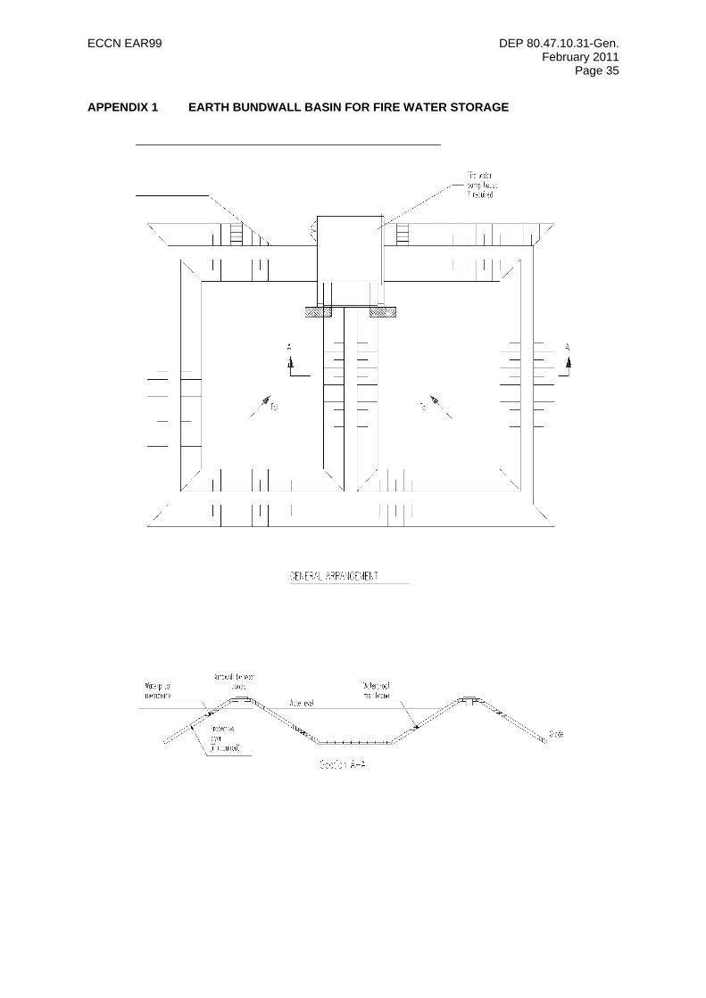
ECCN EAR99 DEP 80.47.10.31-Gen. February 2011
Page 35
APPENDIX 1 EARTH BUNDWALL BASIN FOR FIRE WATER STORAGE
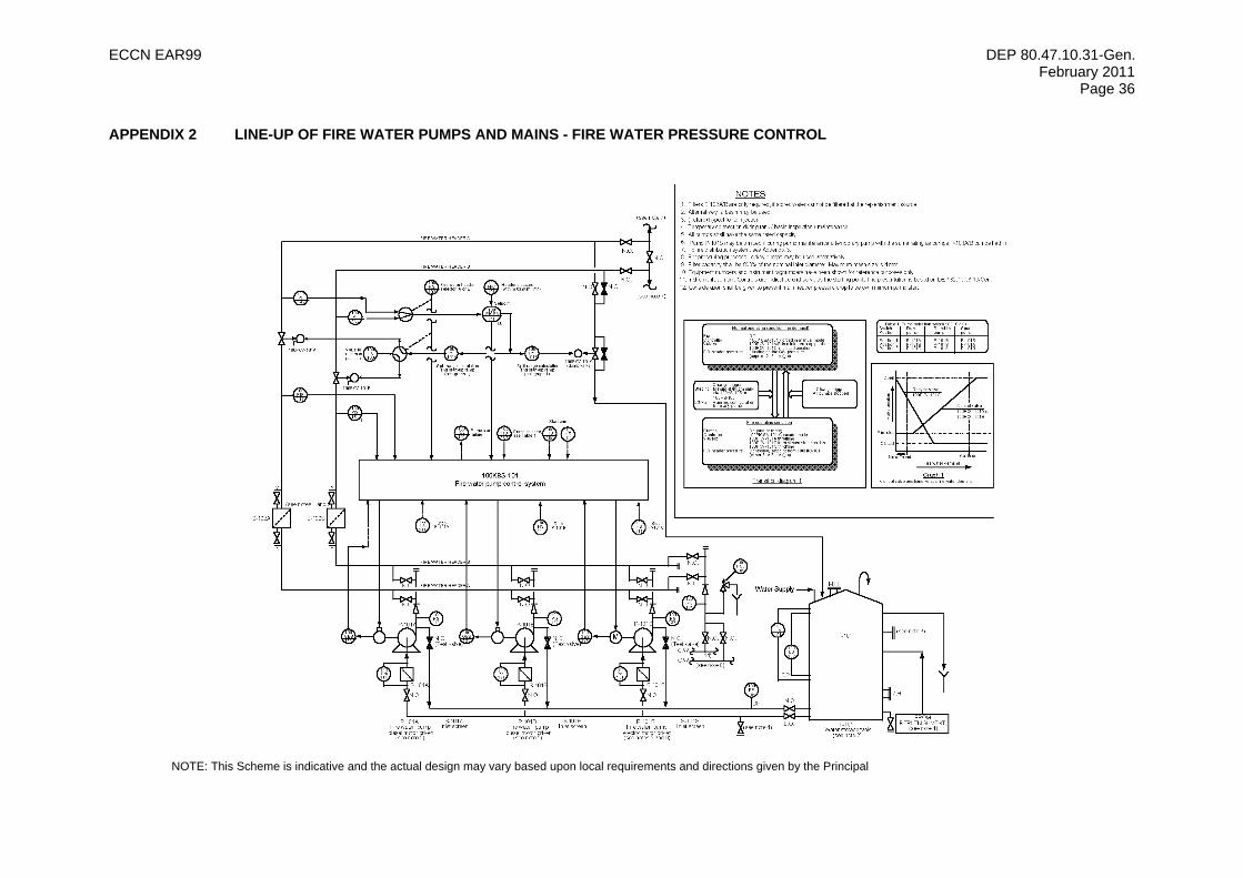
ECCN EAR99 DEP 80.47.10.31-Gen. February 2011
Page 36
APPENDIX 2 LINE-UP OF FIRE WATER PUMPS AND MAINS - FIRE WATER PRESSURE CONTROL
NOTE: This Scheme is indicative and the actual design may vary based upon local requirements and directions given by the Principal
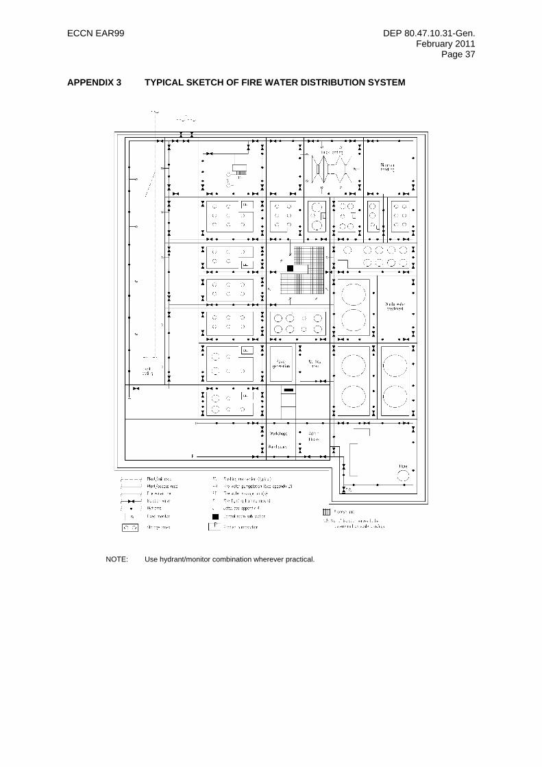
ECCN EAR99 DEP 80.47.10.31-Gen. February 2011
Page 37
APPENDIX 3 TYPICAL SKETCH OF FIRE WATER DISTRIBUTION SYSTEM
NOTE: Use hydrant/monitor combination wherever practical.
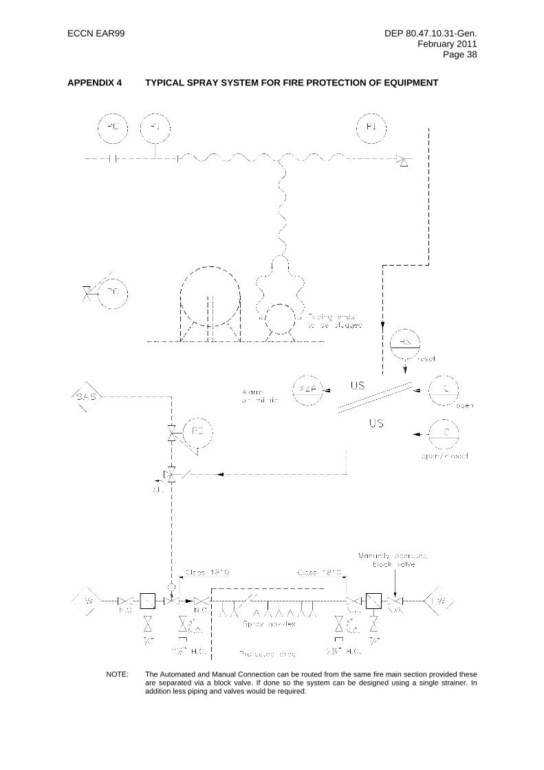
ECCN EAR99 DEP 80.47.10.31-Gen. February 2011
Page 38
APPENDIX 4 TYPICAL SPRAY SYSTEM FOR FIRE PROTECTION OF EQUIPMENT
NOTE: The Automated and Manual Connection can be routed from the same fire main section provided these
are separated via a block valve. If done so the system can be designed using a single strainer. In addition less piping and valves would be required.
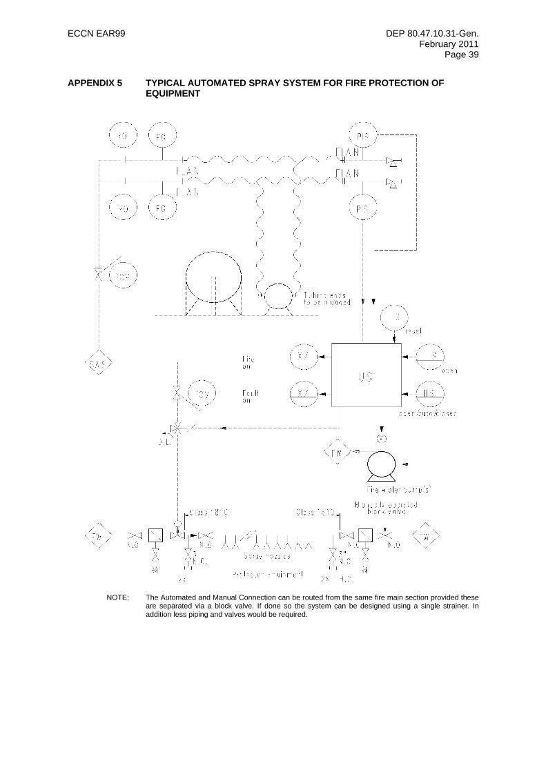
ECCN EAR99 DEP 80.47.10.31-Gen. February 2011
Page 39
APPENDIX 5 TYPICAL AUTOMATED SPRAY SYSTEM FOR FIRE PROTECTION OF EQUIPMENT
NOTE: The Automated and Manual Connection can be routed from the same fire main section provided these
are separated via a block valve. If done so the system can be designed using a single strainer. In addition less piping and valves would be required.
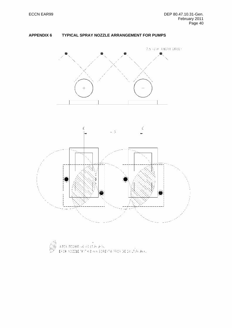
ECCN EAR99 DEP 80.47.10.31-Gen. February 2011
Page 40
APPENDIX 6 TYPICAL SPRAY NOZZLE ARRANGEMENT FOR PUMPS
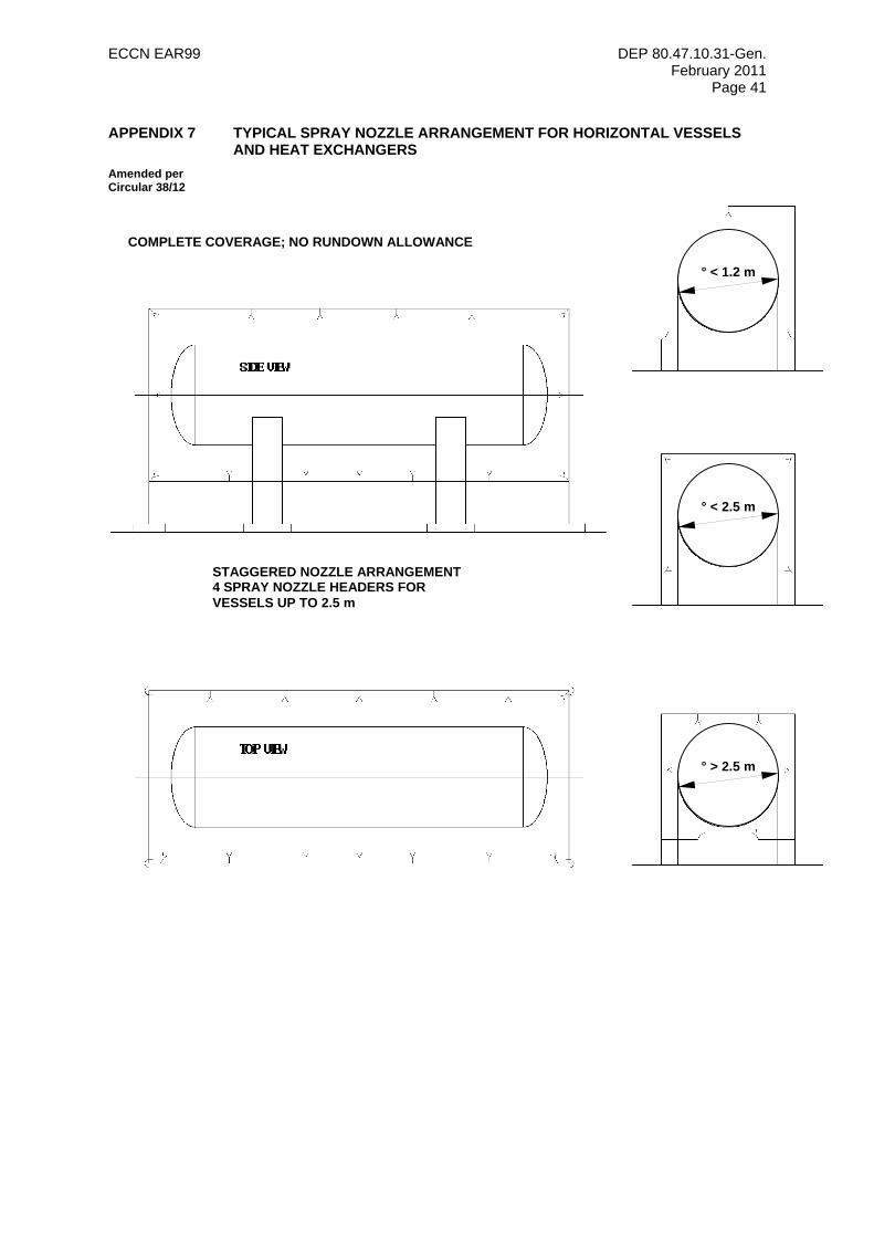
ECCN EAR99 DEP 80.47.10.31-Gen. February 2011
Page 41
APPENDIX 7 TYPICAL SPRAY NOZZLE ARRANGEMENT FOR HORIZONTAL VESSELS AND HEAT EXCHANGERS
Amended per Circular 38/12
° < 1.2 m
° < 2.5 m
° > 2.5 m
STAGGERED NOZZLE ARRANGEMENT4 SPRAY NOZZLE HEADERS FOR VESSELS UP TO 2.5 m
COMPLETE COVERAGE; NO RUNDOWN ALLOWANCE
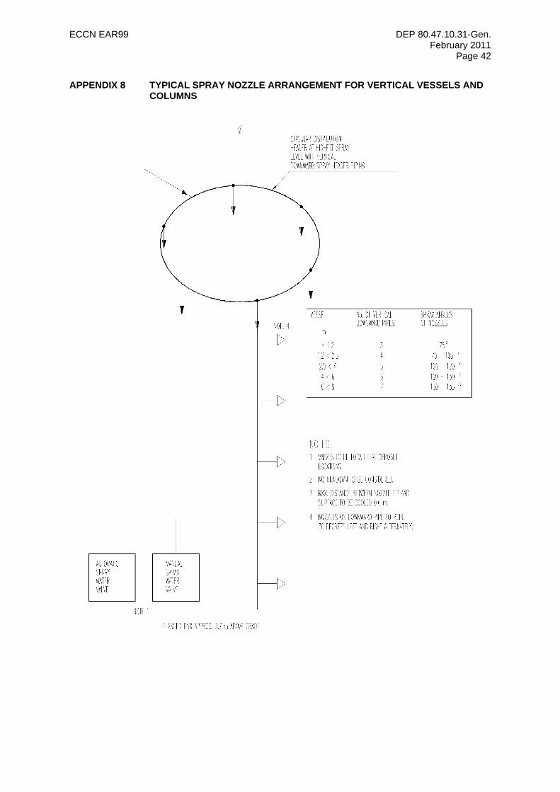
ECCN EAR99 DEP 80.47.10.31-Gen. February 2011
Page 42
APPENDIX 8 TYPICAL SPRAY NOZZLE ARRANGEMENT FOR VERTICAL VESSELS AND COLUMNS
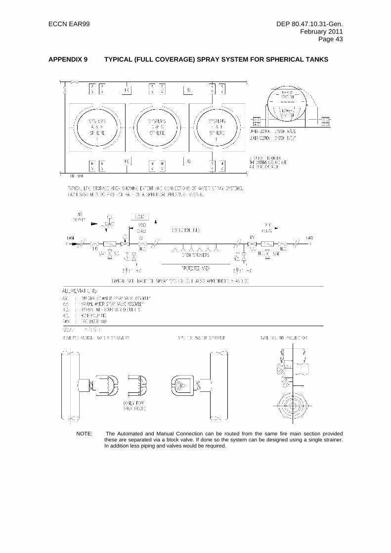
ECCN EAR99 DEP 80.47.10.31-Gen. February 2011
Page 43
APPENDIX 9 TYPICAL (FULL COVERAGE) SPRAY SYSTEM FOR SPHERICAL TANKS
NOTE: The Automated and Manual Connection can be routed from the same fire main section provided
these are separated via a block valve. If done so the system can be designed using a single strainer. In addition less piping and valves would be required.
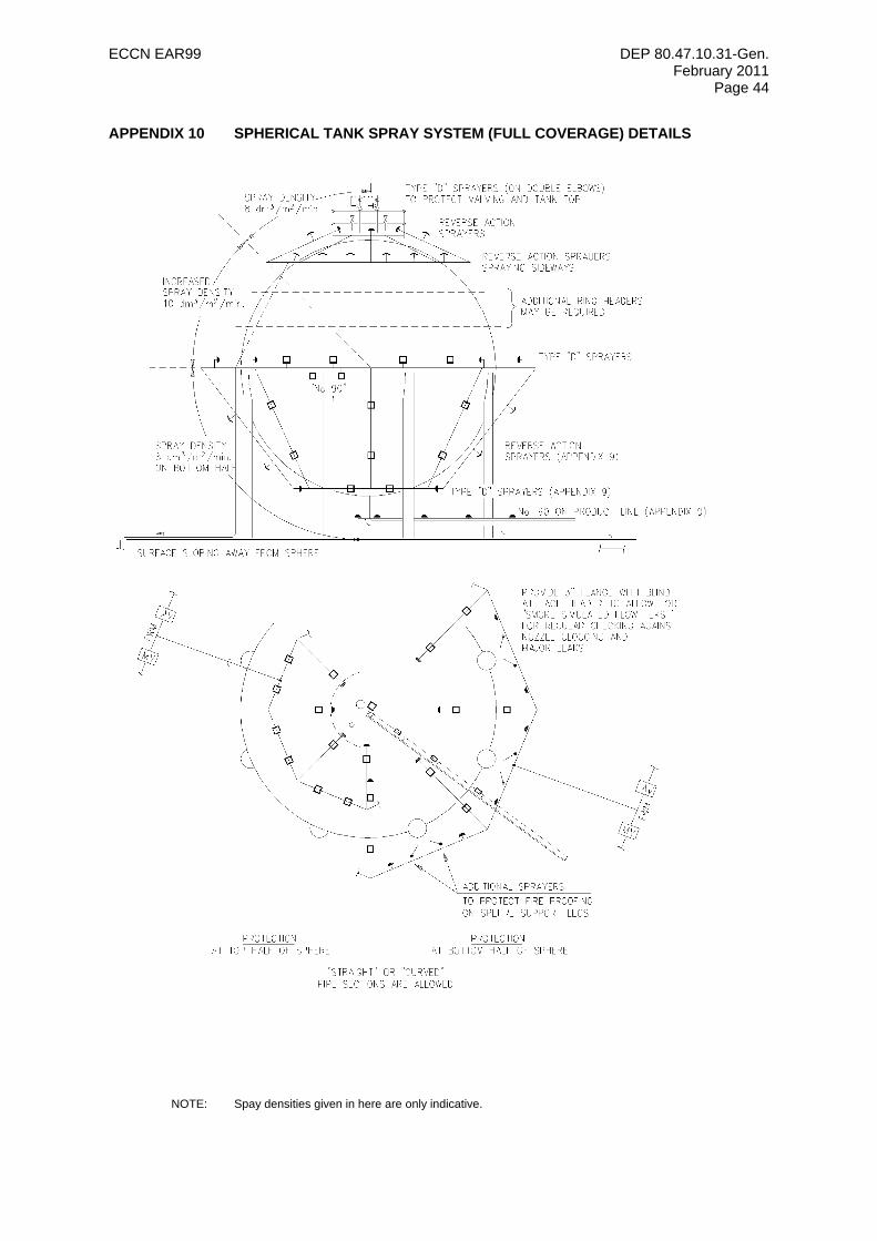
ECCN EAR99 DEP 80.47.10.31-Gen. February 2011
Page 44
APPENDIX 10 SPHERICAL TANK SPRAY SYSTEM (FULL COVERAGE) DETAILS
NOTE: Spay densities given in here are only indicative.
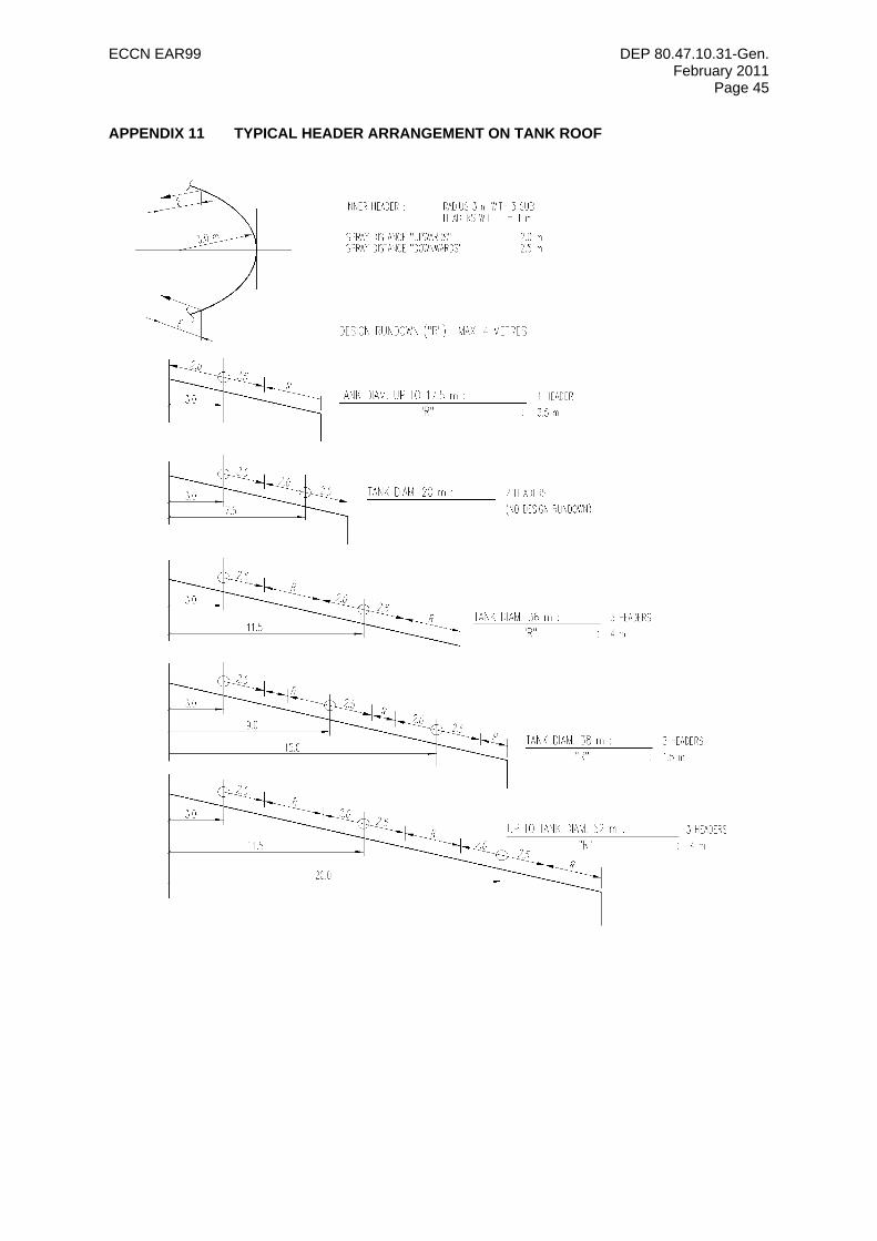
ECCN EAR99 DEP 80.47.10.31-Gen. February 2011
Page 45
APPENDIX 11 TYPICAL HEADER ARRANGEMENT ON TANK ROOF
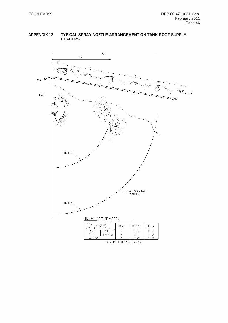
ECCN EAR99 DEP 80.47.10.31-Gen. February 2011
Page 46
APPENDIX 12 TYPICAL SPRAY NOZZLE ARRANGEMENT ON TANK ROOF SUPPLY HEADERS
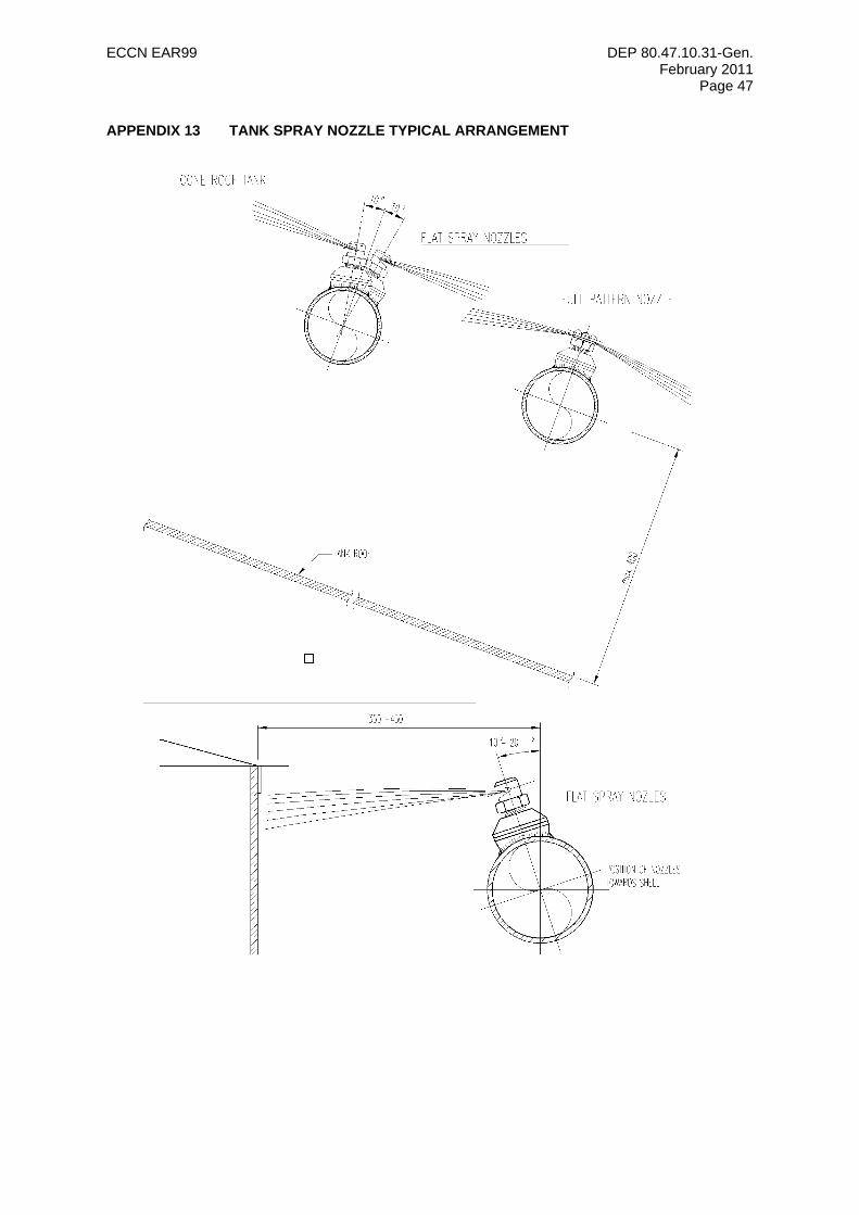
ECCN EAR99 DEP 80.47.10.31-Gen. February 2011
Page 47
APPENDIX 13 TANK SPRAY NOZZLE TYPICAL ARRANGEMENT
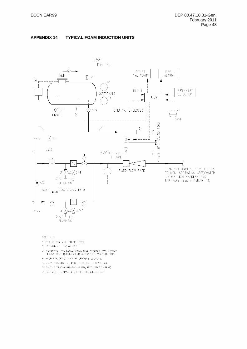
ECCN EAR99 DEP 80.47.10.31-Gen. February 2011
Page 48
APPENDIX 14 TYPICAL FOAM INDUCTION UNITS
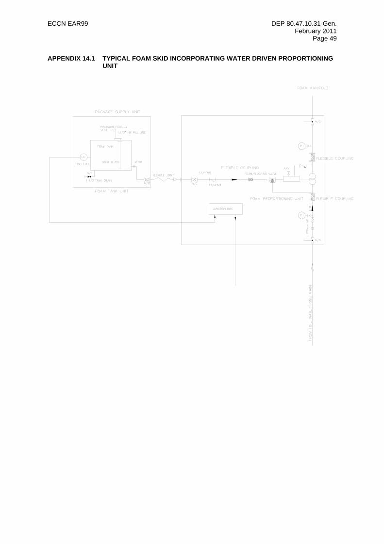
ECCN EAR99 DEP 80.47.10.31-Gen. February 2011
Page 49
APPENDIX 14.1 TYPICAL FOAM SKID INCORPORATING WATER DRIVEN PROPORTIONING UNIT
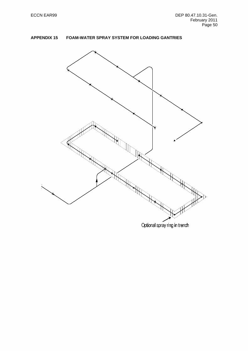
ECCN EAR99 DEP 80.47.10.31-Gen. February 2011
Page 50
APPENDIX 15 FOAM-WATER SPRAY SYSTEM FOR LOADING GANTRIES
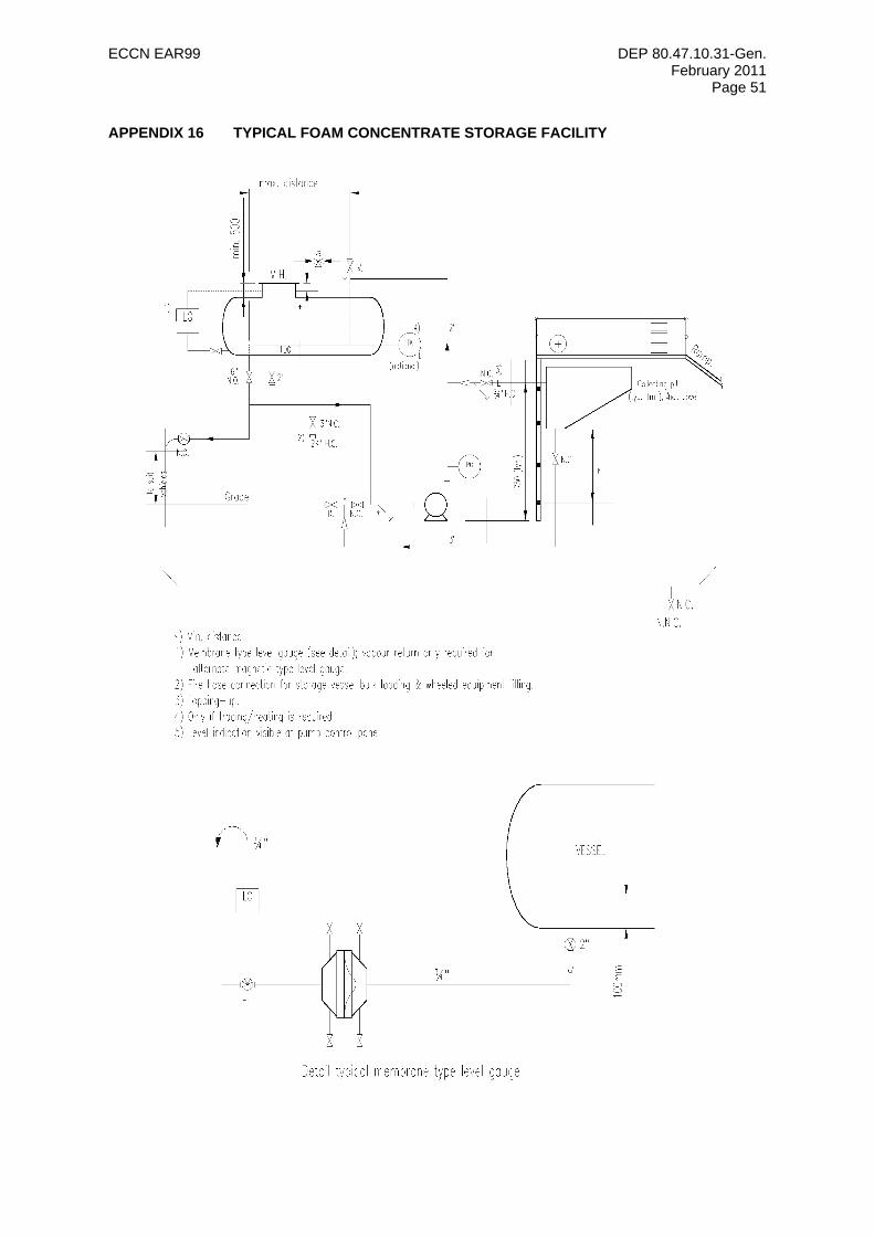
ECCN EAR99 DEP 80.47.10.31-Gen. February 2011
Page 51
APPENDIX 16 TYPICAL FOAM CONCENTRATE STORAGE FACILITY
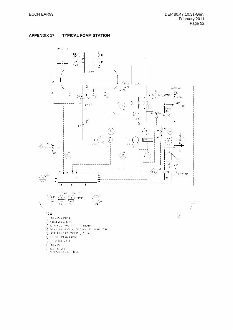
ECCN EAR99 DEP 80.47.10.31-Gen. February 2011
Page 52
APPENDIX 17 TYPICAL FOAM STATION
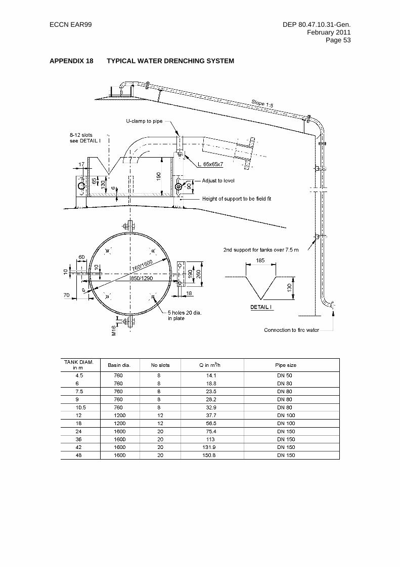
ECCN EAR99 DEP 80.47.10.31-Gen. February 2011
Page 53
APPENDIX 18 TYPICAL WATER DRENCHING SYSTEM
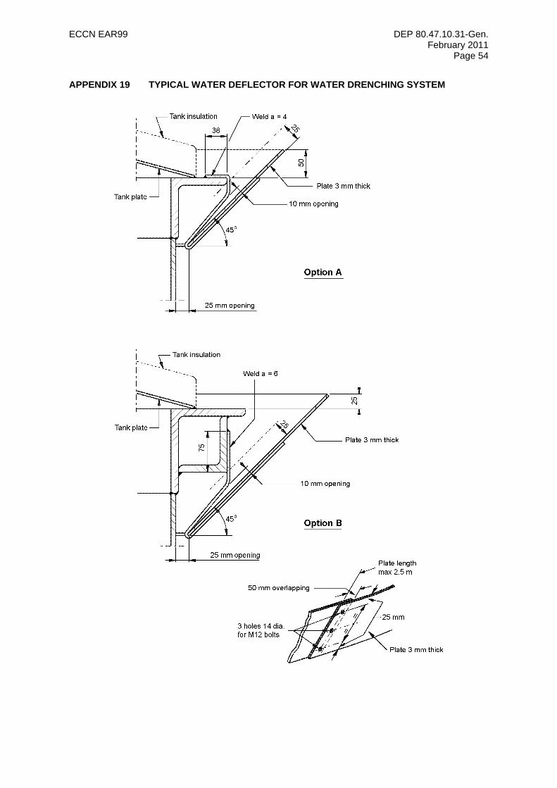
ECCN EAR99 DEP 80.47.10.31-Gen. February 2011
Page 54
APPENDIX 19 TYPICAL WATER DEFLECTOR FOR WATER DRENCHING SYSTEM
ECCN EAR99 DEP 80.47.10.31-Gen. February 2011
Page 55
APPENDIX 20 TYPICAL PERFORMANCE CRITERIA TEMPLATES
The following templates are given as examples for guidance only. They should be used in conjunction with the main text of this DEP in order to develop Performance Criteria specific to a particular installation in the four areas of Functionality, Reliability/Availability, Survivability and Dependencies/Interactions. It should be noted that any application rate figures for systems such as foam or water spray/deluge systems are typical figures that would be applicable in many situations but they should not be used for a specific facility without ensuring that they are relevant.
It is emphasised that these templates are generic in nature. Provision of a template does not imply that the system shall be provided and, in any case, the Performance Criteria shall be facility-specific. The process to be adopted in making them applicable to an individual facility involves, for each type of system to be used:
a) Review of the functions included in the template and revision to reflect the facility-specific basis of design and Fire and Explosion Strategy (FES) when available;
b) Review and, revise of necessary, the appropriate "criteria" which define the design basis of the system;
c) Review and, if necessary revise, the means for verification of the chosen criteria;
d) Inclusion of facility-specific targets such as reliability targets identified in the facility’s QRA, or HEMP;
e) Identification of any fire and explosion loads applicable to the "survivability" elements;
f) Identification of particular "dependent" systems that are assumed to be available for the main system to function.
The process of review and adaptation requires knowledge of the overall FES, the role of the system, and its basis of design and an awareness of the contribution it makes to reduce the level of risk at the facility. As such, it is likely that experienced personnel from the following disciplines will be involved in the conditioning process:
• Technical Safety Engineer or Loss Prevention Engineer;
• Lead discipline Engineer for the system;
• Discipline Maintenance Engineer (for existing facilities);
• Operations staff (for new and existing facilities).
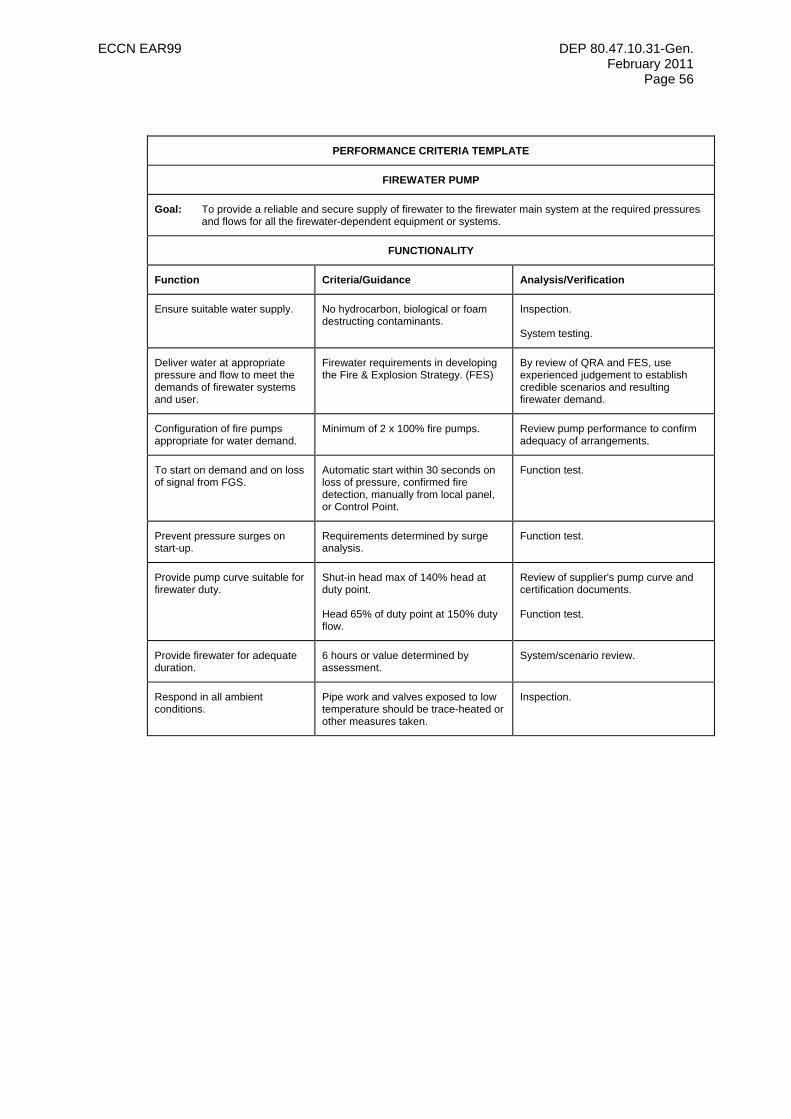
ECCN EAR99 DEP 80.47.10.31-Gen. February 2011
Page 56
PERFORMANCE CRITERIA TEMPLATE
FIREWATER PUMP
Goal: To provide a reliable and secure supply of firewater to the firewater main system at the required pressures and flows for all the firewater-dependent equipment or systems.
FUNCTIONALITY
Function Criteria/Guidance Analysis/Verification
Ensure suitable water supply. No hydrocarbon, biological or foam destructing contaminants.
Inspection. System testing.
Deliver water at appropriate pressure and flow to meet the demands of firewater systems and user.
Firewater requirements in developing the Fire & Explosion Strategy. (FES)
By review of QRA and FES, use experienced judgement to establish credible scenarios and resulting firewater demand.
Configuration of fire pumps appropriate for water demand.
Minimum of 2 x 100% fire pumps. Review pump performance to confirm adequacy of arrangements.
To start on demand and on loss of signal from FGS.
Automatic start within 30 seconds on loss of pressure, confirmed fire detection, manually from local panel, or Control Point.
Function test.
Prevent pressure surges on start-up.
Requirements determined by surge analysis.
Function test.
Provide pump curve suitable for firewater duty.
Shut-in head max of 140% head at duty point. Head 65% of duty point at 150% duty flow.
Review of supplier's pump curve and certification documents. Function test.
Provide firewater for adequate duration.
6 hours or value determined by assessment.
System/scenario review.
Respond in all ambient conditions.
Pipe work and valves exposed to low temperature should be trace-heated or other measures taken.
Inspection.
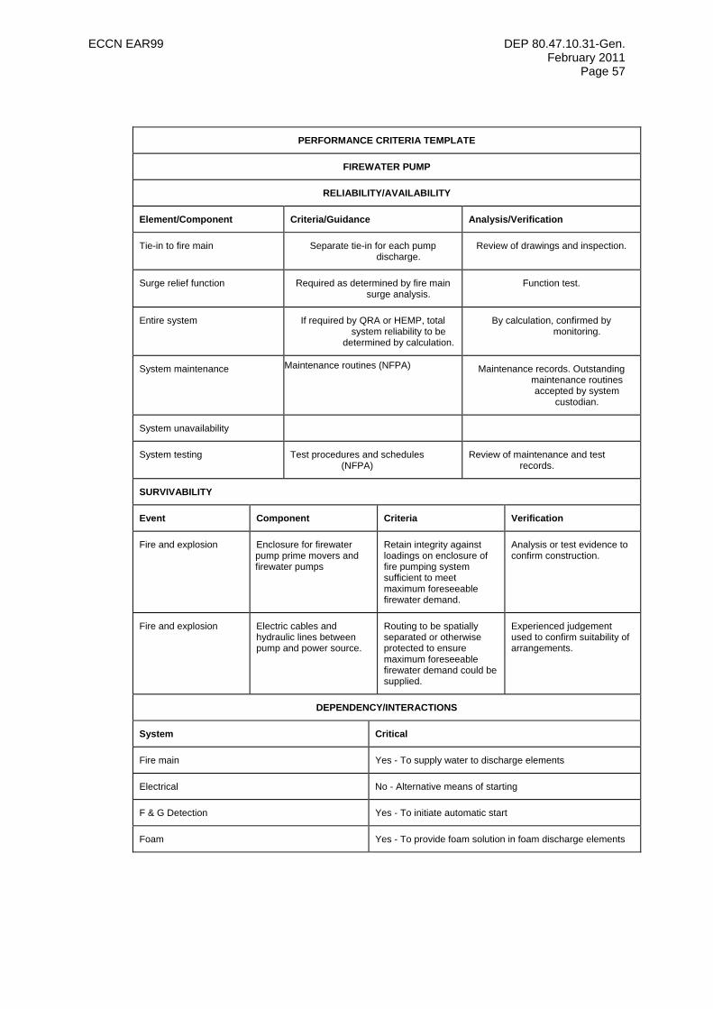
ECCN EAR99 DEP 80.47.10.31-Gen. February 2011
Page 57
PERFORMANCE CRITERIA TEMPLATE
FIREWATER PUMP
RELIABILITY/AVAILABILITY
Element/Component Criteria/Guidance Analysis/Verification
Tie-in to fire main Separate tie-in for each pump discharge.
Review of drawings and inspection.
Surge relief function Required as determined by fire main surge analysis.
Function test.
Entire system If required by QRA or HEMP, total system reliability to be
determined by calculation.
By calculation, confirmed by monitoring.
System maintenance Maintenance routines (NFPA) Maintenance records. Outstanding maintenance routines accepted by system
custodian.
System unavailability
System testing Test procedures and schedules (NFPA)
Review of maintenance and test records.
SURVIVABILITY
Event Component Criteria Verification
Fire and explosion Enclosure for firewater pump prime movers and firewater pumps
Retain integrity against loadings on enclosure of fire pumping system sufficient to meet maximum foreseeable firewater demand.
Analysis or test evidence to confirm construction.
Fire and explosion Electric cables and hydraulic lines between pump and power source.
Routing to be spatially separated or otherwise protected to ensure maximum foreseeable firewater demand could be supplied.
Experienced judgement used to confirm suitability of arrangements.
DEPENDENCY/INTERACTIONS
System Critical
Fire main Yes - To supply water to discharge elements
Electrical No - Alternative means of starting
F & G Detection Yes - To initiate automatic start
Foam Yes - To provide foam solution in foam discharge elements
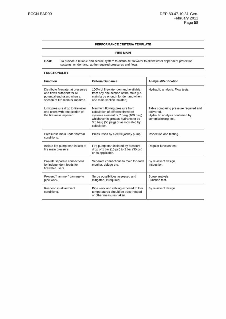
ECCN EAR99 DEP 80.47.10.31-Gen. February 2011
Page 58
PERFORMANCE CRITERIA TEMPLATE
FIRE MAIN
Goal: To provide a reliable and secure system to distribute firewater to all firewater dependent protection systems, on demand, at the required pressures and flows.
FUNCTIONALITY
Function Criteria/Guidance Analysis/Verification
Distribute firewater at pressures and flows sufficient for all potential end users when a section of fire main is impaired.
100% of firewater demand available from any one section of fire main (i.e. main large enough for demand when one main section isolated).
Hydraulic analysis. Flow tests.
Limit pressure drop to firewater end users with one section of the fire main impaired.
Minimum flowing pressure from calculation of different firewater systems element or 7 barg (100 psig) whichever is greater; hydrants to be 3.5 barg (50 psig) or as indicated by calculation.
Table comparing pressure required and delivered. Hydraulic analysis confirmed by commissioning test.
Pressurise main under normal conditions.
Pressurised by electric jockey pump. Inspection and testing.
Initiate fire pump start in loss of fire main pressure.
Fire pump start initiated by pressure drop of 1 bar (15 psi) to 2 bar (30 psi) or as applicable.
Regular function test.
Provide separate connections for independent feeds for firewater users.
Separate connections to main for each monitor, deluge etc.
By review of design. Inspection.
Prevent "hammer" damage to pipe work.
Surge possibilities assessed and mitigated, if required.
Surge analysis. Function test.
Respond in all ambient conditions.
Pipe work and valving exposed to low temperatures should be trace-heated or other measures taken.
By review of design.
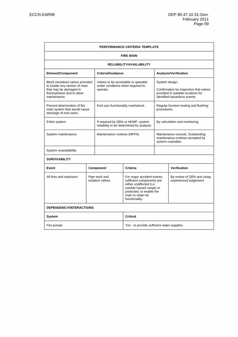
ECCN EAR99 DEP 80.47.10.31-Gen. February 2011
Page 59
PERFORMANCE CRITERIA TEMPLATE
FIRE MAIN
RELIABILITY/AVAILABILITY
Element/Component Criteria/Guidance Analysis/Verification
Block (isolation) valves provided to isolate any section of main that may be damaged in fire/explosion and to allow maintenance.
Valves to be accessible or operable under conditions when required to operate.
System design. Confirmation by inspection that valves provided in suitable locations for identified hazardous events.
Prevent deterioration of fire main system that would cause blockage of end users.
End user functionality maintained. Regular function testing and flushing procedures.
Entire system If required by QRA or HEMP, system reliability to be determined by analysis.
By calculation and monitoring.
System maintenance. Maintenance routines (NFPA) Maintenance records. Outstanding maintenance routines accepted by system custodian.
System unavailability
SURVIVABILITY
Event Component Criteria Verification
All fires and explosion Pipe work and isolation valves.
For major accident events, sufficient components are either unaffected (i.e. outside hazard range) or protected, to enable fire main to retain its functionality.
By review of QRA and using experienced judgement.
DEPENDENCY/INTERACTIONS
System Critical
Fire pumps Yes - to provide sufficient water supplies.
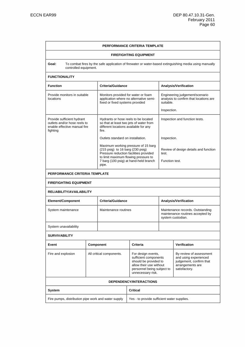
ECCN EAR99 DEP 80.47.10.31-Gen. February 2011
Page 60
PERFORMANCE CRITERIA TEMPLATE
FIREFIGHTING EQUIPMENT
Goal: To combat fires by the safe application of firewater or water-based extinguishing media using manually controlled equipment.
FUNCTIONALITY
Function Criteria/Guidance Analysis/Verification
Provide monitors in suitable locations
Monitors provided for water or foam application where no alternative semi-fixed or fixed systems provided
Engineering judgement/scenario analysis to confirm that locations are suitable. Inspection.
Provide sufficient hydrant outlets and/or hose reels to enable effective manual fire fighting
Hydrants or hose reels to be located so that at least two jets of water from different locations available for any fire. Outlets standard on installation. Maximum working pressure of 15 barg (215 psig) to 16 barg (230 psig) Pressure reduction facilities provided to limit maximum flowing pressure to 7 barg (100 psig) at hand-held branch pipe.
Inspection and function tests. Inspection. Review of design details and function test. Function test.
PERFORMANCE CRITERIA TEMPLATE
FIREFIGHTING EQUIPMENT
RELIABILITY/AVAILABILITY
Element/Component Criteria/Guidance Analysis/Verification
System maintenance Maintenance routines Maintenance records. Outstanding maintenance routines accepted by system custodian.
System unavailability
SURVIVABILITY
Event Component Criteria Verification
Fire and explosion All critical components. For design events, sufficient components should be provided to allow their use without personnel being subject to unnecessary risk.
By review of assessment and using experienced judgement, confirm that arrangements are satisfactory.
DEPENDENCY/INTERACTIONS
System Critical
Fire pumps, distribution pipe work and water supply Yes - to provide sufficient water supplies.
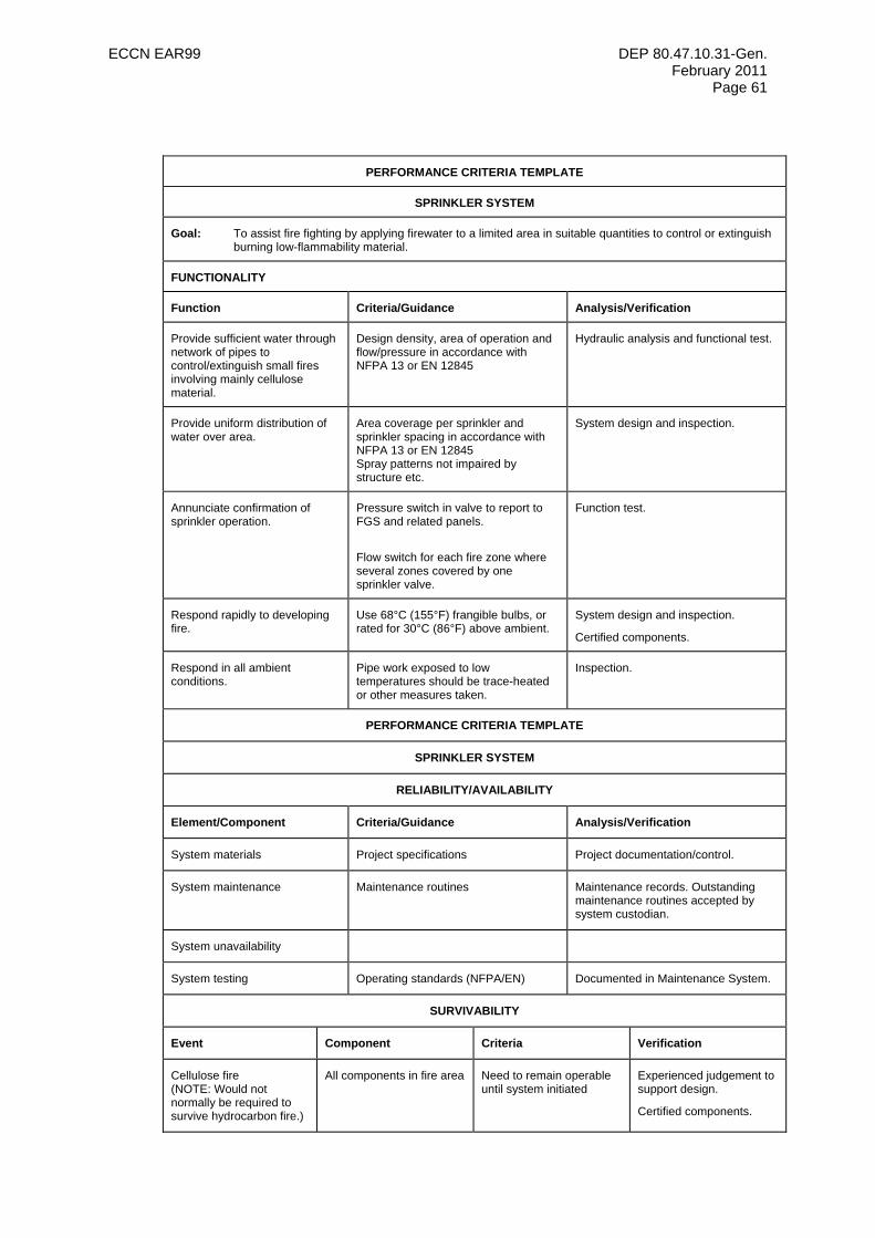
ECCN EAR99 DEP 80.47.10.31-Gen. February 2011
Page 61
PERFORMANCE CRITERIA TEMPLATE
SPRINKLER SYSTEM
Goal: To assist fire fighting by applying firewater to a limited area in suitable quantities to control or extinguish burning low-flammability material.
FUNCTIONALITY
Function Criteria/Guidance Analysis/Verification
Provide sufficient water through network of pipes to control/extinguish small fires involving mainly cellulose material.
Design density, area of operation and flow/pressure in accordance with NFPA 13 or EN 12845
Hydraulic analysis and functional test.
Provide uniform distribution of water over area.
Area coverage per sprinkler and sprinkler spacing in accordance with NFPA 13 or EN 12845 Spray patterns not impaired by structure etc.
System design and inspection.
Annunciate confirmation of sprinkler operation.
Pressure switch in valve to report to FGS and related panels.
Flow switch for each fire zone where several zones covered by one sprinkler valve.
Function test.
Respond rapidly to developing fire.
Use 68°C (155°F) frangible bulbs, or rated for 30°C (86°F) above ambient.
System design and inspection.
Certified components.
Respond in all ambient conditions.
Pipe work exposed to low temperatures should be trace-heated or other measures taken.
Inspection.
PERFORMANCE CRITERIA TEMPLATE
SPRINKLER SYSTEM
RELIABILITY/AVAILABILITY
Element/Component Criteria/Guidance Analysis/Verification
System materials Project specifications Project documentation/control.
System maintenance Maintenance routines Maintenance records. Outstanding maintenance routines accepted by system custodian.
System unavailability
System testing Operating standards (NFPA/EN) Documented in Maintenance System.
SURVIVABILITY
Event Component Criteria Verification
Cellulose fire (NOTE: Would not normally be required to survive hydrocarbon fire.)
All components in fire area Need to remain operable until system initiated
Experienced judgement to support design.
Certified components.

ECCN EAR99 DEP 80.47.10.31-Gen. February 2011
Page 62
DEPENDENCY/INTERACTIONS
System Critical
Fire pump, distribution pipe work and water supply Yes - to provide sufficient water on demand.
FGS (Fire & Gas Detection System) Yes - to initiate firewater demand.
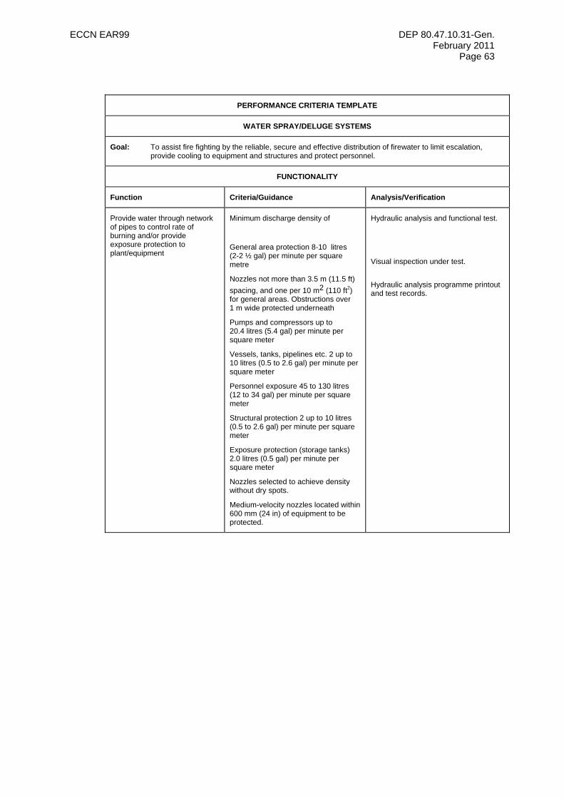
ECCN EAR99 DEP 80.47.10.31-Gen. February 2011
Page 63
PERFORMANCE CRITERIA TEMPLATE
WATER SPRAY/DELUGE SYSTEMS
Goal: To assist fire fighting by the reliable, secure and effective distribution of firewater to limit escalation, provide cooling to equipment and structures and protect personnel.
FUNCTIONALITY
Function Criteria/Guidance Analysis/Verification
Provide water through network of pipes to control rate of burning and/or provide exposure protection to plant/equipment
Minimum discharge density of
General area protection 8-10 litres (2-2 ½ gal) per minute per square metre
Nozzles not more than 3.5 m (11.5 ft) spacing, and one per 10 m2 (110 ft2) for general areas. Obstructions over 1 m wide protected underneath
Pumps and compressors up to 20.4 litres (5.4 gal) per minute per square meter
Vessels, tanks, pipelines etc. 2 up to 10 litres (0.5 to 2.6 gal) per minute per square meter
Personnel exposure 45 to 130 litres (12 to 34 gal) per minute per square meter
Structural protection 2 up to 10 litres (0.5 to 2.6 gal) per minute per square meter
Exposure protection (storage tanks) 2.0 litres (0.5 gal) per minute per square meter
Nozzles selected to achieve density without dry spots.
Medium-velocity nozzles located within 600 mm (24 in) of equipment to be protected.
Hydraulic analysis and functional test.
Visual inspection under test.
Hydraulic analysis programme printout and test records.
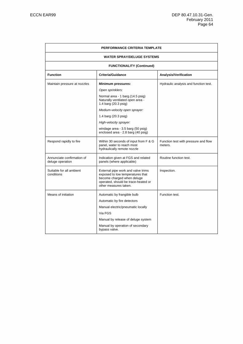
ECCN EAR99 DEP 80.47.10.31-Gen. February 2011
Page 64
PERFORMANCE CRITERIA TEMPLATE
WATER SPRAY/DELUGE SYSTEMS
FUNCTIONALITY (Continued)
Function Criteria/Guidance Analysis/Verification
Maintain pressure at nozzles Minimum pressures:
Open sprinklers:
Normal area - 1 barg.(14.5 psig) Naturally ventilated open area - 1.4 barg (20.3 psig)
Medium-velocity open sprayer:
1.4 barg (20.3 psig)
High-velocity sprayer:
windage area - 3.5 barg (50 psig) enclosed area - 2.8 barg (40 psig)
Hydraulic analysis and function test.
Respond rapidly to fire Within 30 seconds of input from F & G panel, water to reach most hydraulically remote nozzle
Function test with pressure and flow meters.
Annunciate confirmation of deluge operation
Indication given at FGS and related panels (where applicable)
Routine function test.
Suitable for all ambient conditions
External pipe work and valve trims exposed to low temperatures that become charged when deluge operated, should be trace-heated or other measures taken.
Inspection.
Means of initiation Automatic by frangible bulb
Automatic by fire detectors
Manual electric/pneumatic locally
Via FGS
Manual by release of deluge system
Manual by operation of secondary bypass valve.
Function test.
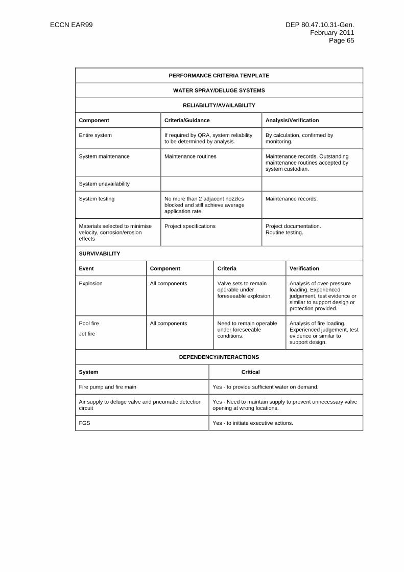
ECCN EAR99 DEP 80.47.10.31-Gen. February 2011
Page 65
PERFORMANCE CRITERIA TEMPLATE
WATER SPRAY/DELUGE SYSTEMS
RELIABILITY/AVAILABILITY
Component Criteria/Guidance Analysis/Verification
Entire system If required by QRA, system reliability to be determined by analysis.
By calculation, confirmed by monitoring.
System maintenance Maintenance routines Maintenance records. Outstanding maintenance routines accepted by system custodian.
System unavailability
System testing No more than 2 adjacent nozzles blocked and still achieve average application rate.
Maintenance records.
Materials selected to minimise velocity, corrosion/erosion effects
Project specifications Project documentation. Routine testing.
SURVIVABILITY
Event Component Criteria Verification
Explosion All components Valve sets to remain operable under foreseeable explosion.
Analysis of over-pressure loading. Experienced judgement, test evidence or similar to support design or protection provided.
Pool fire
Jet fire
All components Need to remain operable under foreseeable conditions.
Analysis of fire loading. Experienced judgement, test evidence or similar to support design.
DEPENDENCY/INTERACTIONS
System Critical
Fire pump and fire main Yes - to provide sufficient water on demand.
Air supply to deluge valve and pneumatic detection circuit
Yes - Need to maintain supply to prevent unnecessary valve opening at wrong locations.
FGS Yes - to initiate executive actions.
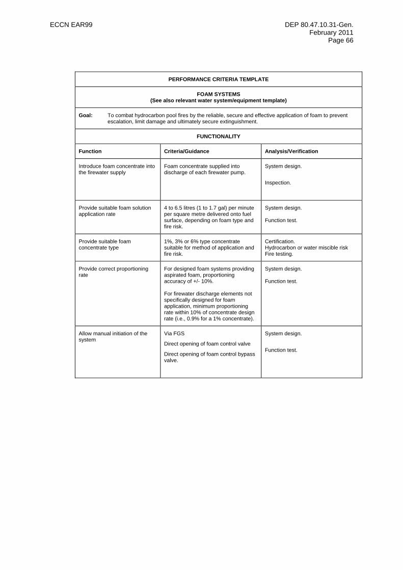
ECCN EAR99 DEP 80.47.10.31-Gen. February 2011
Page 66
PERFORMANCE CRITERIA TEMPLATE
FOAM SYSTEMS (See also relevant water system/equipment template)
Goal: To combat hydrocarbon pool fires by the reliable, secure and effective application of foam to prevent escalation, limit damage and ultimately secure extinguishment.
FUNCTIONALITY
Function Criteria/Guidance Analysis/Verification
Introduce foam concentrate into the firewater supply
Foam concentrate supplied into discharge of each firewater pump.
System design.
Inspection.
Provide suitable foam solution application rate
4 to 6.5 litres (1 to 1.7 gal) per minute per square metre delivered onto fuel surface, depending on foam type and fire risk.
System design. Function test.
Provide suitable foam concentrate type
1%, 3% or 6% type concentrate suitable for method of application and fire risk.
Certification. Hydrocarbon or water miscible risk Fire testing.
Provide correct proportioning rate
For designed foam systems providing aspirated foam, proportioning accuracy of +/- 10%. For firewater discharge elements not specifically designed for foam application, minimum proportioning rate within 10% of concentrate design rate (i.e., 0.9% for a 1% concentrate).
System design. Function test.
Allow manual initiation of the system
Via FGS
Direct opening of foam control valve
Direct opening of foam control bypass valve.
System design.
Function test.
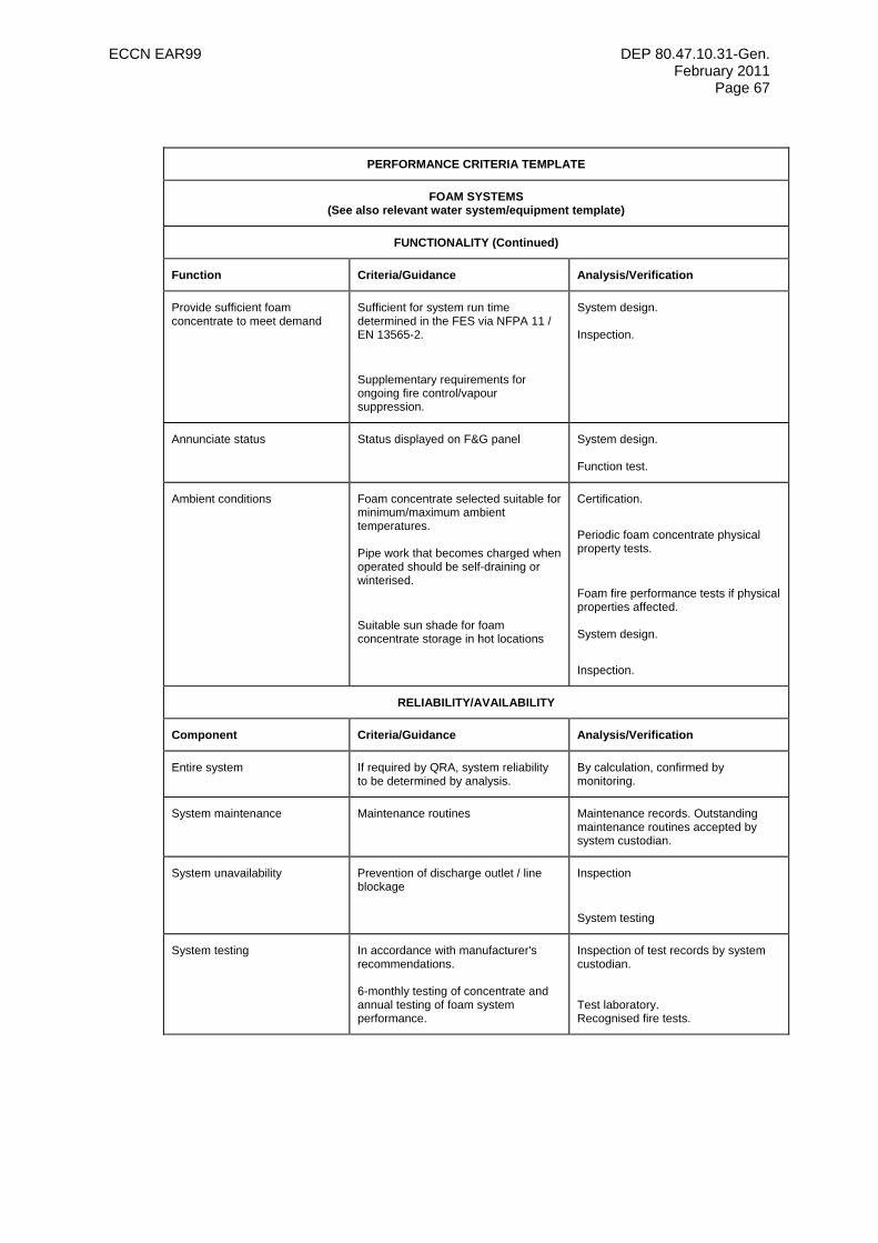
ECCN EAR99 DEP 80.47.10.31-Gen. February 2011
Page 67
PERFORMANCE CRITERIA TEMPLATE
FOAM SYSTEMS (See also relevant water system/equipment template)
FUNCTIONALITY (Continued)
Function Criteria/Guidance Analysis/Verification
Provide sufficient foam concentrate to meet demand
Sufficient for system run time determined in the FES via NFPA 11 / EN 13565-2.
Supplementary requirements for ongoing fire control/vapour suppression.
System design. Inspection.
Annunciate status Status displayed on F&G panel System design. Function test.
Ambient conditions Foam concentrate selected suitable for minimum/maximum ambient temperatures. Pipe work that becomes charged when operated should be self-draining or winterised.
Suitable sun shade for foam concentrate storage in hot locations
Certification.
Periodic foam concentrate physical property tests.
Foam fire performance tests if physical properties affected. System design.
Inspection.
RELIABILITY/AVAILABILITY
Component Criteria/Guidance Analysis/Verification
Entire system If required by QRA, system reliability to be determined by analysis.
By calculation, confirmed by monitoring.
System maintenance Maintenance routines Maintenance records. Outstanding maintenance routines accepted by system custodian.
System unavailability Prevention of discharge outlet / line blockage
Inspection
System testing
System testing In accordance with manufacturer's recommendations. 6-monthly testing of concentrate and annual testing of foam system performance.
Inspection of test records by system custodian. Test laboratory. Recognised fire tests.
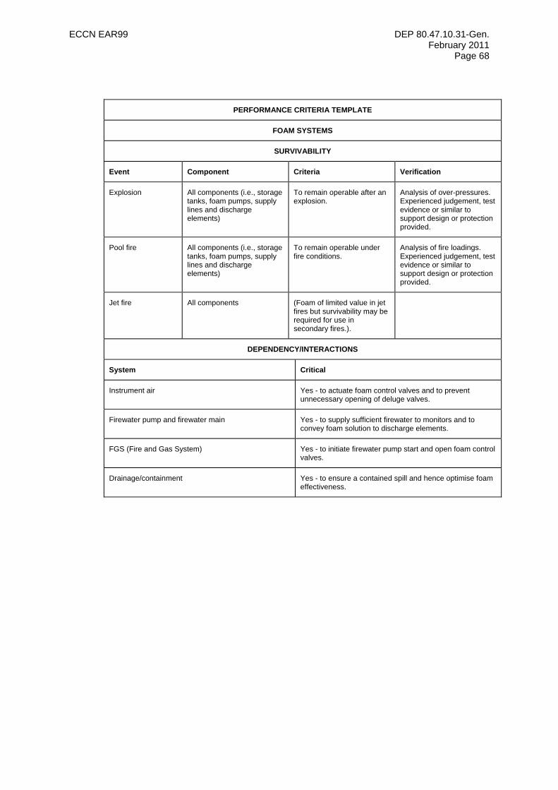
ECCN EAR99 DEP 80.47.10.31-Gen. February 2011
Page 68
PERFORMANCE CRITERIA TEMPLATE
FOAM SYSTEMS
SURVIVABILITY
Event Component Criteria Verification
Explosion All components (i.e., storage tanks, foam pumps, supply lines and discharge elements)
To remain operable after an explosion.
Analysis of over-pressures. Experienced judgement, test evidence or similar to support design or protection provided.
Pool fire All components (i.e., storage tanks, foam pumps, supply lines and discharge elements)
To remain operable under fire conditions.
Analysis of fire loadings. Experienced judgement, test evidence or similar to support design or protection provided.
Jet fire All components (Foam of limited value in jet fires but survivability may be required for use in secondary fires.).
DEPENDENCY/INTERACTIONS
System Critical
Instrument air Yes - to actuate foam control valves and to prevent unnecessary opening of deluge valves.
Firewater pump and firewater main Yes - to supply sufficient firewater to monitors and to convey foam solution to discharge elements.
FGS (Fire and Gas System) Yes - to initiate firewater pump start and open foam control valves.
Drainage/containment Yes - to ensure a contained spill and hence optimise foam effectiveness.
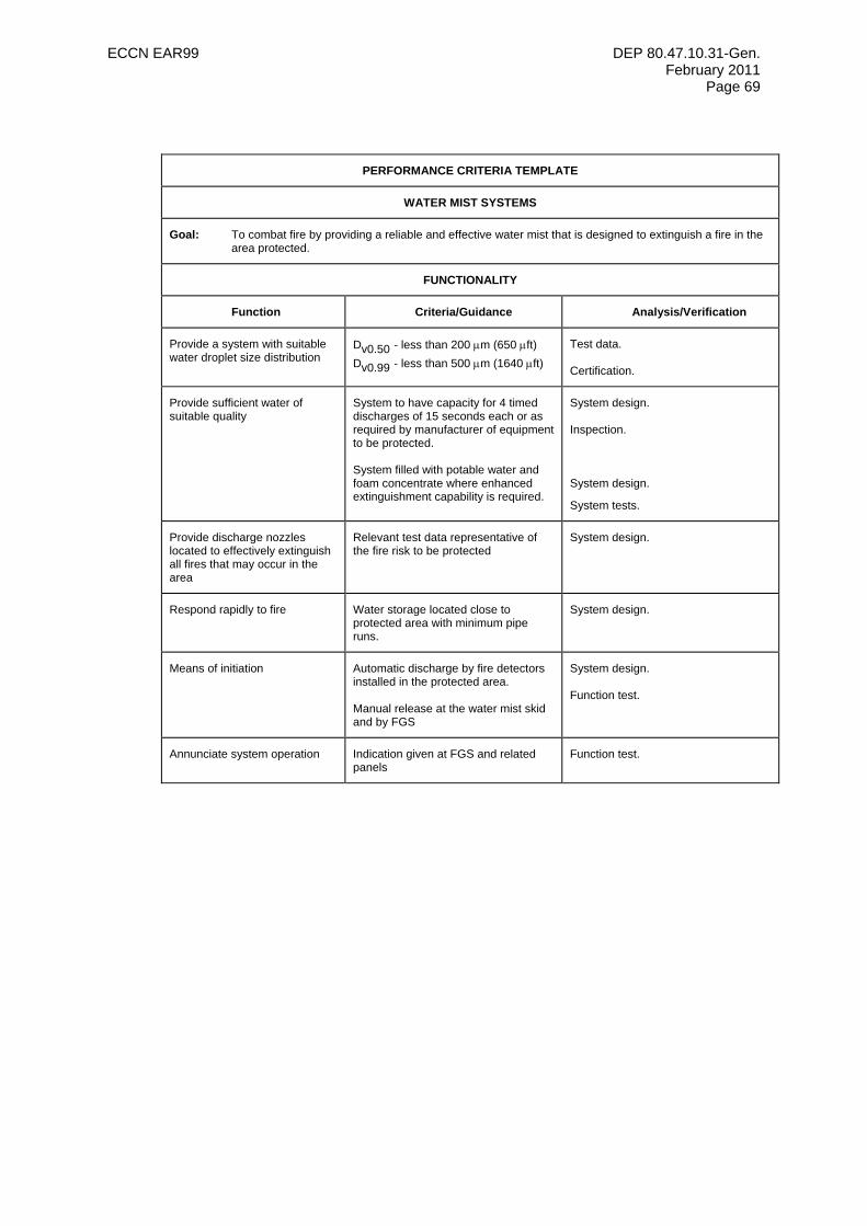
ECCN EAR99 DEP 80.47.10.31-Gen. February 2011
Page 69
PERFORMANCE CRITERIA TEMPLATE
WATER MIST SYSTEMS
Goal: To combat fire by providing a reliable and effective water mist that is designed to extinguish a fire in the area protected.
FUNCTIONALITY
Function Criteria/Guidance Analysis/Verification
Provide a system with suitable water droplet size distribution
Dv0.50 - less than 200 µm (650 µft) Dv0.99 - less than 500 µm (1640 µft)
Test data. Certification.
Provide sufficient water of suitable quality
System to have capacity for 4 timed discharges of 15 seconds each or as required by manufacturer of equipment to be protected. System filled with potable water and foam concentrate where enhanced extinguishment capability is required.
System design. Inspection. System design.
System tests.
Provide discharge nozzles located to effectively extinguish all fires that may occur in the area
Relevant test data representative of the fire risk to be protected
System design.
Respond rapidly to fire Water storage located close to protected area with minimum pipe runs.
System design.
Means of initiation Automatic discharge by fire detectors installed in the protected area. Manual release at the water mist skid and by FGS
System design. Function test.
Annunciate system operation Indication given at FGS and related panels
Function test.
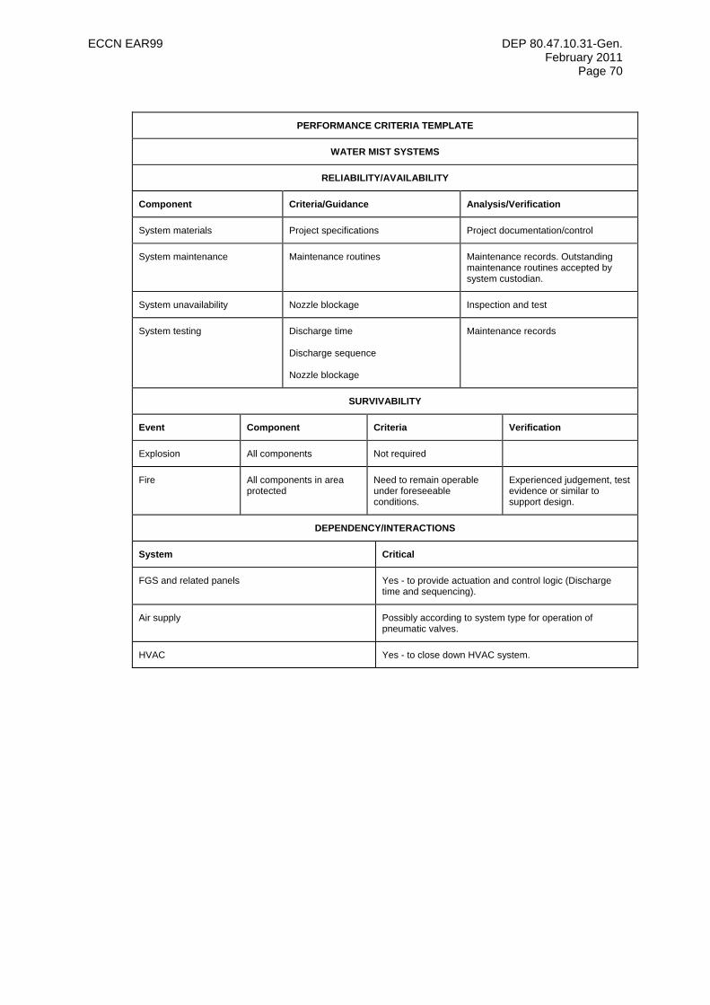
ECCN EAR99 DEP 80.47.10.31-Gen. February 2011
Page 70
PERFORMANCE CRITERIA TEMPLATE
WATER MIST SYSTEMS
RELIABILITY/AVAILABILITY
Component Criteria/Guidance Analysis/Verification
System materials Project specifications Project documentation/control
System maintenance Maintenance routines Maintenance records. Outstanding maintenance routines accepted by system custodian.
System unavailability Nozzle blockage Inspection and test
System testing Discharge time Discharge sequence Nozzle blockage
Maintenance records
SURVIVABILITY
Event Component Criteria Verification
Explosion All components Not required
Fire All components in area protected
Need to remain operable under foreseeable conditions.
Experienced judgement, test evidence or similar to support design.
DEPENDENCY/INTERACTIONS
System Critical
FGS and related panels Yes - to provide actuation and control logic (Discharge time and sequencing).
Air supply Possibly according to system type for operation of pneumatic valves.
HVAC Yes - to close down HVAC system.