Embed Size (px)
Citation preview
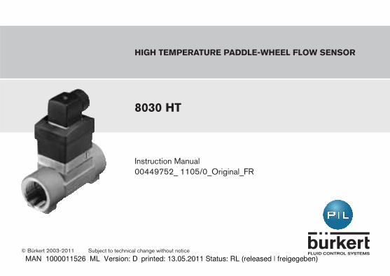
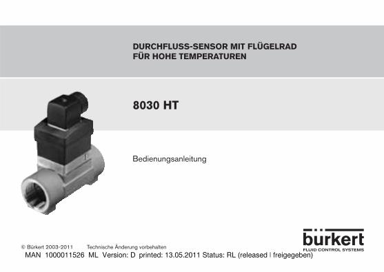
Instruction Manual
high temperature paddle-wheel FlOw SeNSOr
8030 ht
© Bürkert 2003-2011 Subject to technical change without notice
00449752_ 1105/0_Original_FR
ENGLISH
ENGLISH
Flow Sensor 8030 ht
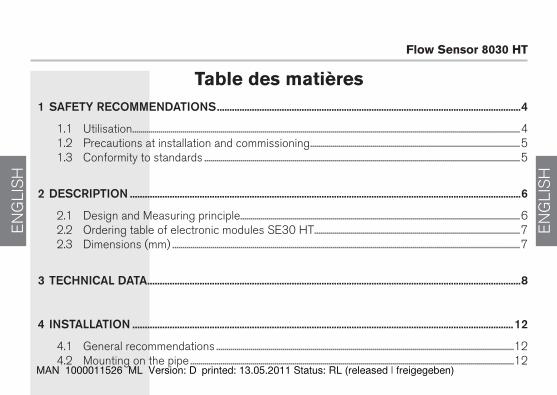
table des matières1safetyrecommendations��������������������������������������������������������������������������������������������������������������������������4
1.1 Utilisation ..................................................................................................................................................................................................41.2 Precautions at installation and commissioning .........................................................................................................51.3 Conformity to standards ..............................................................................................................................................................5
2description�������������������������������������������������������������������������������������������������������������������������������������������������������������6
2.1 Design and Measuring principle............................................................................................................................................62.2 Ordering table of electronic modules SE30 HT .......................................................................................................72.3 Dimensions (mm) ..............................................................................................................................................................................7
3technicaldata������������������������������������������������������������������������������������������������������������������������������������������������������8
4installation���������������������������������������������������������������������������������������������������������������������������������������������������������12
4.1 General recommendations .....................................................................................................................................................124.2 Mounting on the pipe ..................................................................................................................................................................12
8030 ht 3
ENGLISH
ENGLISH
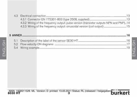
4.3 Electrical connection ...................................................................................................................................................................13 4.3.1 Connector EN 175301-803 (type 2508, supplied) ...........................................................................13 4.3.2 Wiring of the frequency output: pulse version (transistor outputs NPN and PNP)...14 4.3.3 Wiring of the frequency output: sinusoidal version (coil output) ..............................................15
5annex��������������������������������������������������������������������������������������������������������������������������������������������������������������������������16
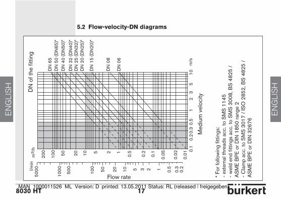
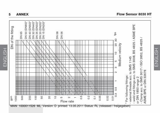
5.1 Description of the label of the sensor SE30 HT ..................................................................................................165.2 Flow-velocity-DN diagrams ..................................................................................................................................................175.4 Wiring example .................................................................................................................................................................................19
ENGLISH
ENGLISH
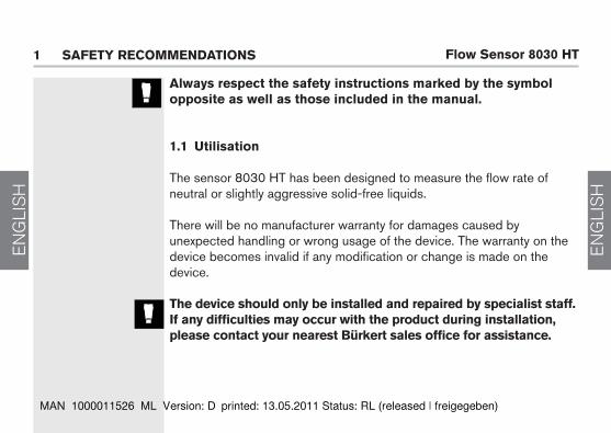
Flow Sensor 8030 ht1 SaFety recOmmeNdatiONS
always respect the safety instructions marked by the symbolopposite as well as those included in the manual.
1.1 utilisation
The sensor 8030 HT has been designed to measure the flow rate of neutral or slightly aggressive solid-free liquids.
There will be no manufacturer warranty for damages caused byunexpected handling or wrong usage of the device. The warranty on the device becomes invalid if any modification or change is made on the device.
the device should only be installed and repaired by specialist staff. if any difficulties may occur with the product during installation, please contact your nearest Bürkert sales office for assistance.

8030 ht 5
ENGLISH
ENGLISH
1.2 precautions at installation and commissioning
- Always ensure the materials in contact with the medium to measure are chemically compatible with this medium.- To clean the device, only use chemically compatible products. - Always protect the device from electromagnetic perturbations, ultraviolet radiations and, when installed outside, from the effects of climatic conditions.
when dismounting the sensor from the pipe, take all the necessary precautions linked to the process.
1.3 conformity to standards
EMC: EN 50081-1, 61000-6-2 Security: EN 61010-1 Vibration: EN 60068-2-6 Shock: EN 60068-2-27

ENGLISH
ENGLISH
Flow Sensor 8030 ht2 deScriptiON
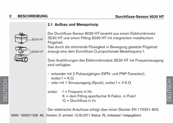
2.1 design and measuring principle
The flow sensor 8030 HT is built up with an electronic module SE30 HT associated to a fitting S030 HT with integrated metallic paddle-wheel.The sensor detects the rotation of the paddle-wheel which produces a signal whose frequency f is proportional to the flow rate Q.
Two electronic module versions with frequency output are available:
- either with 2 pulse outputs (transistor NPN and PNP), where f = K.Q - or with one sinusoidal output (coil), where f = 2 K.Q
where f = frequency in Hz K = K factor specific to each fitting in pulses/l, Q = flow rate in l/s
The electrical connection is carried out via an EN 175301-803 connector.
SE30 HT
S030 HT
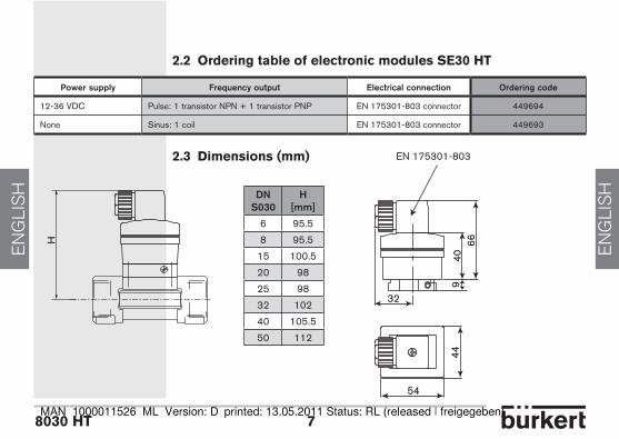
8030 ht 7
ENGLISH
ENGLISH
32
4066
44
54
9
EN 175301-803
2.2 Ordering table of electronic modules Se30 ht
2.3 dimensions (mm)
powersupply frequencyoutput electricalconnection orderingcode
12-36 VDC Pulse: 1 transistor NPN + 1 transistor PNP EN 175301-803 connector 449694
None Sinus: 1 coil EN 175301-803 connector 449693
dns030
h[mm]
6 95.5
8 95.5
15 100.5
20 98
25 98
32 102
40 105.5
50 112
H
ENGLISH
ENGLISH
Flow Sensor 8030 ht
general featuresPipe diameter DN6 to DN50 (DN65 on request); determine the appropriate diameter using the flow- velocity-DN diagrams (see Annex)Medium temperature -15 °C up to 125 °C Medium pressure PN40 if Tfluid < 90 °C PN25 if 90 °C < Tfluid < 125 °C Medium viscosity max. 300 cStRate of solid particles max. 1%Measuring range 0,5 m/s to 10 m/sAccuracy ≤ ±1 % of the full scale*, with calibration on site (for example, using the teach-in feature of a transmitter 8025, remote version) ≤ ± (1 % of the full scale* + 3% of the measured value), with standard K factorLinearity ≤ ± 0.5 % of the full scale*Repeatability 0.4% of the measured valueMeasuring element metallic paddle-wheel of the stainless steel S030 HT fitting
* full scale = 10 m/selectrical features
Sinus versionPower supply noneOutput data up to 500 Hz, about 2.8 mV peak-to-peak/Hz when loaded with 50 kΩ (frequency = 2 x K factor x flow rate; for the value of the K factor, refer to the instruction manual of the fitting)Cable length max. 5 m, shielded
3 techNical data
8030 ht 9
ENGLISH
ENGLISH
pulse versionPower supply 12-36 VDC, filtered and regulatedCurrent consumption ≤ 10 mA (no load)Protection against polarity reversal yesOutput data transistor NPN and PNP, open collector, 700 mA max., NPN output: 0,2-30 VDC and PNP output: supply voltage (see example in the Annex) frequency: up to 250 Hz (frequency = K factor x flow rate; for the value of the K factor, refer to the instruction manual of the fitting)Protection against short-circuits yesCable length max. 50 m, shielded (up to 500 m depending on the cable impedance and the current consumption)
electrical connectionPulse or sinus version EN 175301-803 connector (type 2508, supplied) Type of cable recommended shielded, wire section between 0.14 and 0.5 mm2
materialsHousing / Cable gland PPS, glass fiber reinforced / PAFitting S030HT, paddle-wheel stainless steelBearings of fitting S030HT IglidurSeal / axis of fitting S030HT FKM / ceramicsenvironmentAmbient temperature - pulse version: -15 to +80° C(operating and storage) - sinusoidal version: -15 to +100° CRelative humidity <80%, non condensatedProtection rating (housing) IP 65, connector plugged-in and tightened
ENGLISH
ENGLISH
Flow Sensor 8030 ht
1 92 3 4 5 6 7 8 10
4
8
20
-4
-8
-12
-16
-20
1v.
%
+ 3P.E. S./F. / E. v.% M./ o.R./V.M.
1v.
%
P.E. S./F. / E.
16
12
with calibration on site
without calibration on site, but standard K factor
Medium velocity in m/s
max. error %
F.S = Full scaleo.R. = of Reading (measured value)
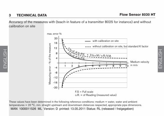
These values have been determined in the following reference conditions: medium = water, water and ambient temperatures = 20 °C, min. straight upstream and downstream distances respected, appropriate pipe dimensions.
3 techNical data
Accuracy of the measures with (teach-in feature of a transmitter 8025 for instance) and without calibration on site
Mea
surin
g er
ror -
% o
f the
mea
sure
8030 ht 11
ENGLISH
ENGLISH
ENGLISH
ENGLISH
Flow Sensor 8030 ht4 iNStallatiON
4.1 general recommendations
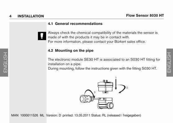
Always check the chemical compatibility of the materials the sensor is made of with the products it may be in contact with.For more information, please contact your Bürkert sales office.
4.2 mounting on the pipe
The electronic module SE30 HT is associated to an S030 HT fitting for installation on a pipe. During mounting, follow the instructions given with the fitting S030 HT.
1
2
3

8030 ht 13
ENGLISH
ENGLISH
4.3 electrical connectionAlways ensure the power supply is switched off before working on the device. The connector must be plugged out.Use:- an earthed shielded cable with an operating temperature suited to the process conditions- a high quality voltage supply (filtered and regulated).
install an appropriate fuse for the power supply.
4.3.1 connector eN 175301-803 (type 2508, supplied)
- Remove part [2] from part [4].- Unscrew the cable gland [6]. - Insert cable into part [4] via cable gland and seal [5].- Wire part [2] (see 4.3.2 or 4.3.3)- Once wired, replace part [2] back into part [4].- Tighten the cable gland [6].- Place flat gasket [1] between the connector and the fixed connector of the 8030HT.- Connect the connector to the 8030HT.- Tighten screw [3] to ensure tightness and correct electrical contact.
1
34
5
6
2
ENGLISH
ENGLISH
Flow Sensor 8030 ht
PNP
0 V
V+ V+
IN
0 V
1
4
3
NPN
0 V
V+ V+
IN
0 V
1
2
3
4 iNStallatiON
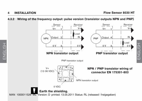
NpN transistor output pNp transistor output
Sensor SensorReceiver
Load
Receiver
Load
NpN / pNp transistor wiring of connector eN 175301-803
V+(12-36 VDC)
NPN transistor output
0 VDC
OutputOutput
4.3.2 wiring of the frequency output: pulse version (transistor outputs NpN and pNp)
PNP transistor output
earth the shielding.
1
32
4
8030 ht 15
ENGLISH
ENGLISH
3
2
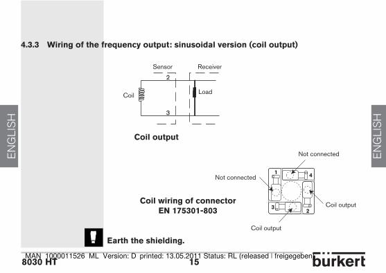
4.3.3 wiring of the frequency output: sinusoidal version (coil output)
earth the shielding.
Not connected
Coil output
Not connected
Coil output
coil output
Sensor Receiver
Coil Load
coil wiring of connector eN 175301-803
1
32
4
ENGLISH
ENGLISH
Flow Sensor 8030 ht
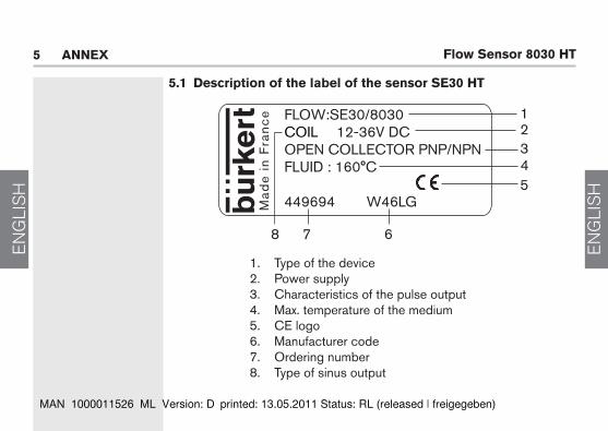
5.1 description of the label of the sensor Se30 ht
5 aNNex
1. Type of the device2. Power supply3. Characteristics of the pulse output4. Max. temperature of the medium5. CE logo6. Manufacturer code7. Ordering number8. Type of sinus output
FLOW:SE30/8030COIL 12-36V DCOPEN COLLECTOR PNP/NPNFLUID : 160°C
449694 W46LGMad
e i
n F
ran
ce 1
23
5
7 6
4
8
8030 ht 17
ENGLISH
ENGLISH
l/min
DN
65
DN
50
(DN
65)*
DN
40
(DN
50)*
DN
32
(DN
40)*
DN
25
(DN
32)*
DN
20
(DN
25)*
DN
15
(DN
20)*
5000
1000 10
0 3 2 120 10 0.55 0.3
0.2
500
50
0.01
0.02
0.050.1
0.2
0.5125102050100
200
m3
/h 0.1
0.3
0.5
12
35
100.
2m
/s
DN
08
DN
06
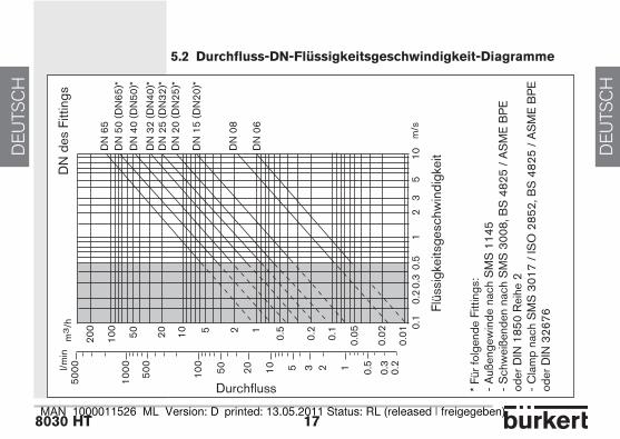
5.2 Flow-velocity-dN diagrams
Flow rate
DN
of t
he fi
tting
Med
ium
vel
ocity
* Fo
r fol
low
ing
fittin
gs:
- ex
tern
al th
read
s ac
c. to
SM
S 1
145
- w
eld
end
fittin
gs a
cc. t
o S
MS
300
8, B
S 4
825
/ A
SM
E B
PE
or D
IN 1
850
rang
e 2
- C
lam
p ac
c. to
SM
S 3
017
/ IS
O 2
852,
BS
482
5 /
AS
ME
BP
E o
r DIN
326
76
ENGLISH
ENGLISH
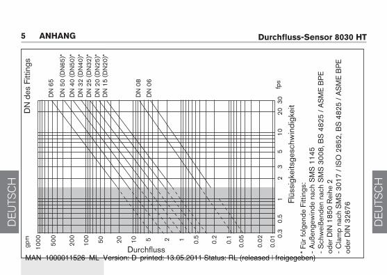
Flow Sensor 8030 htgp
m
1000 50
0
200
20 10 5 2 1 0.5
0.2
0.1
0.05
0.02
0.01
3020
0.3
0.5
12
35
10
DN
65
100
50
fps
DN
08
DN
06
DN
50
(DN
65)*
DN
40
(DN
50)*
DN
32
(DN
40)*
DN
25
(DN
32)*
DN
20
(DN
25)*
DN
15
(DN
20)*
Flow rate
DN
of t
he fi
tting
Med
ium
vel
ocity
5 aNNex
* Fo
r fol
low
ing
fittin
gs:
- ex
tern
al th
read
s ac
c. to
SM
S 1
145
- w
eld
end
fittin
gs a
cc. t
o S
MS
300
8, B
S 4
825
/ A
SM
E B
PE
or
DIN
185
0 ra
nge
2 -
Cla
mp
acc.
to S
MS
301
7 /
ISO
285
2, B
S 4
825
/ A
SM
E B
PE
or D
IN 3
2676
8030 ht 19
ENGLISH
ENGLISH
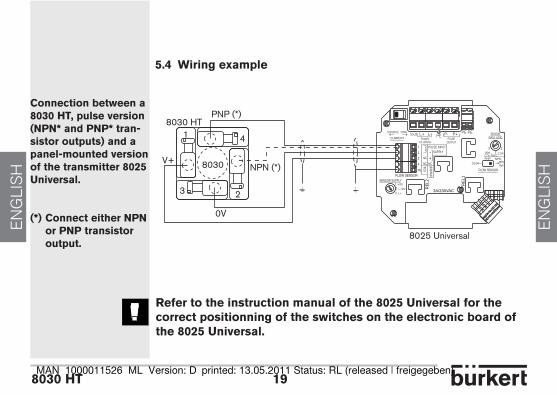
5.4 wiring example
connection between a 8030 ht, pulse version (NpN* and pNp* tran-sistor outputs) and a panel-mounted version of the transmitter 8025 universal.
(*) connect either NpN or pNp transistor output.
refer to the instruction manual of the 8025 universal for the correct positionning of the switches on the electronic board of the 8025 universal.
NPN (*)
PNP (*)8030 HT
1
3 2
V+
0V
8030
4
NPN/
PNP
SUPPLY
COIL
1
234
PE
NC
3A/230VAC
RE
L1
RE
L2SENSOR SUPPLY
FLOW SENSOR
COIL NPNPNP
FLOW SENSOR
SOURCE SINK
CURRENTIout L+ L-
Supply13..30Vdc
PEPE PE
NCNC+-
PULSE INPUT
123 L+
+12V
+5V
P- P+PULSE
OUTPUT
SENSORINPUT LOAD
12
339K
NPN470
2.2KCOILPNP
8025 Universal
ENGLISH
ENGLISH
Flow Sensor 8030 ht5 aNNex
Bedienungsanleitung
durchfluss-sensor mit flügelradfür hohe temperaturen
8030 ht
© Bürkert 2003-2011 Technische Änderung vorbehalten
DEU
TSCH
DEU
TSCH
durchfluss-sensor 8030 ht
inhaltsverzeichnis1ALLGEMEINESICHERHEITSHINWEISE��������������������������������������������������������������������������������������������������������4
1.1 Bestimmungsgemäße Verwendung ...................................................................................................................................41.2 Gefahren bei der Installation und Inbetriebnahme .................................................................................................51.3 Normenbezüge ....................................................................................................................................................................................5
2BESCHREIBUNG�������������������������������������������������������������������������������������������������������������������������������������������������������6
2.1 Aufbau und Messprinzip ..............................................................................................................................................................62.2 Ausführungen des Elektronikmoduls SE30 HT .......................................................................................................72.3 Abmessungen (mm) ........................................................................................................................................................................7
3TECHNISCHEDATEN����������������������������������������������������������������������������������������������������������������������������������������������8
4INSTALLATION���������������������������������������������������������������������������������������������������������������������������������������������������������12
4.1 Allgemeine Hinweise ...................................................................................................................................................................124.2 Einbau in die Rohrleitung .........................................................................................................................................................12
8030 ht 3
DEU
TSCH
DEU
TSCH
4.3 Elektrischer Anschluss ..............................................................................................................................................................13 4.3.1 Anschlussstecker EN 175301-803 (Typ 2508, geliefert) ............................................................13 4.3.2 Steckerverbindung des Frequenzausgangs: Puls-Version (NPN- und PNP ..................14 Transistor-Ausgänge) ...................................................................................................................................................14 4.3.3 Steckerverbindung des Frequenzausgangs: Sinus-Version (Spule-Ausgang) .............15
5ANHANG����������������������������������������������������������������������������������������������������������������������������������������������������������������������16
5.1 Beschreibung des Typenschilds des SE30 HT .....................................................................................................165.2 Durchfluss-DN-Flüssigkeitsgeschwindigkeit-Diagramme ...........................................................................175.4 Anschluss-Beispiel ........................................................................................................................................................................19
DEU
TSCH
DEU
TSCH
durchfluss-sensor 8030 ht1 allgemeine sicherheitshinWeise
Beachten sie in jedem fall die nachfolgenden und in den erläuterungen aufgeführten sicherheitshinweise. die Kennzeichung der sicherheitshinweise erfolgt durch das nebenstehende symbol.
1.1 Bestimmungsgemäße Verwendung
Der Sensor 8030 HT darf nur zur Durchflussmessung in teilchenfreien neutralen oder leicht aggressiven Flüssigkeiten eingesetzt werden.
Für Schäden aus unsachgemässem oder nicht bestimmungsgemässem Gebrauch haftet der Hersteller nicht. An dem Gerät dürfen keine Umbauten oder Veränderungen vorgenommen werden.
einbau und/oder reparatur dürfen nur durch eingewiesenes personal erfolgen. sollten bei der installation oder der inbetriebnahme schwierigkeiten auftreten, setzen sie sich bitte mit Bürkert in Verbindung.
8030 ht 5
DEU
TSCH
DEU
TSCH
1.2 gefahren bei der installation und inbetriebnahme - Beachten Sie bei speziellen Messmedien, inkl. Medien für die Reinigung, die Materialbeständigkeit von mediumsberührendenTeilen. - Schützen Sie das Gerät von elektromagnetischen Störungen, von Ultraviolettbestrahlung und, bei einer Außenanwendung, von den Wetterbedingungen.
dem verwendeten prozess entsprechend müssen geeignete Vor-sichtsmaßnahmen getroffen werden, bevor der sensor abgebaut wird.
1.3 normenbezüge
EMV: EN 50081-1, 61000-6-2Sicherheit: EN 61010-1Vibration: EN 60068-2-6Stoß: EN 60068-2-27
DEU
TSCH
DEU
TSCH
durchfluss-sensor 8030 ht2 BeschreiBung
2.1 aufbau und messprinzip
Der Durchfluss-Sensor 8030 HT besteht aus einem Elektronikmodul SE30 HT und einem Fitting S030 HT mit integriertem metallischem Flügelrad.Das durch die strömende Flüssigkeit in Bewegung gesetzte Flügelrad erzeugt eine dem Durchfluss Q proportionale Messfrequenz f.
Zwei Ausführungen des Elektronikmoduls SE30 HT mit Frequenzausgang sind verfügbar:
- entweder mit 2 Pulsausgängen (NPN- und PNP-Transistor), wobei f = K.Q - oder mit 1 Sinusausgang (Spule), wobei f = 2 K.Q
wobei f = Frequenz in Hz K = dem Fitting spezifischer K-Faktor, in Puls/l Q = Durchfluss in l/s
Der elektrische Anschluss erfolgt über einen Stecker EN 175301-803.
SE30 HT
S030 HT
8030 ht 7
DEU
TSCH
DEU
TSCH
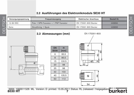
2.2 ausführungen des elektronikmoduls se30 ht
2.3 abmessungen (mm)
Versorgungsspannung Frequenzausgang ElektrischerAnschluss Bestell-Nr�
12-36 VDC Puls: 1 NPN-Transistor + 1 PNP-Transistor EN 175301-803 Stecker 449694
Keine Sinusförmig: 1 Spule EN 175301-803 Stecker 449693
H
DNS030
H[mm]
6 95.5
8 95.5
15 100.5
20 98
25 98
32 102
40 105.5
50 112
32
4066
44
54
9
EN 175301-803
DEU
TSCH
DEU
TSCH
durchfluss-sensor 8030 ht3 technische daten
allgemeine daten
Rohrleitungsdurchmesser DN6 bis DN50 (DN65 auf Anfrage); Verwenden Sie die Durchfluss-Geschwindigkeits- Diagramme im Anhang, um den geeigneten Rohrleitungsdurchmesser auszuwählen.Flüssigkeits-Temperatur -15 °C bis 125 °CFlüssigkeits-Druck PN40 bei TFlüssigkeit < 90 °C PN25 bei 90 °C < TFlüssigkeit < 125 °C Flüssigkeits-Viskosität max. 300 cStFeststoffanteil max. 1%Messbereich 0,5 m/s bis 10 m/sGenauigkeit ≤ ±1 % vom Endwert*, mit Kalibrierung vor Ort (zum Beispiel, Teach-In-Funktion eines Transmitters 8025 in getrennter Ausführung) ≤ ± (1 % vom Endwert* + 3% vom Messwert), mit standard K-FaktorLinearität ≤ ±0.5 % vom Endwert*Wiederholbarkeit 0.4% vom Messwert Messelement Metallisches Flügelrad des Edelstahl-Fittings S030 HT * Endwert = 10 m/selektrische daten
sinus-VersionSpannungsversorgung KeineAusgangsdaten bis 500 Hz, Spitze-Spitze-Spannung von ungefähr 2.8 mV/Hz unter einer 50 kW-Ladung (Frequenz = 2 x K-Faktor x Durchfluss; Der K-Faktor-Wert kann aus der Bedienungsanleitung des Fittings gelesen werden)Kabellänge max. 50 m, abgeschirmt
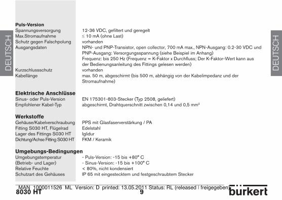
8030 ht 9
DEU
TSCH
DEU
TSCH
puls-VersionSpannungsversorgung 12-36 VDC, gefiltert und geregeltMax.Stromaufnahme ≤ 10 mA (ohne Last)Schutz gegen Falschpolung vorhandenAusgangsdaten NPN- und PNP-Transistor, open collector, 700 mA max., NPN-Ausgang: 0.2-30 VDC und PNP-Ausgang: Versorgungsspannung (siehe Beispiel im Anhang) Frequenz: bis 250 Hz (Frequenz = K-Faktor x Durchfluss; Der K-Faktor-Wert kann aus der Bedienungsanleitung des Fittings gelesen werden)Kurzschlussschutz vorhandenKabellänge max. 50 m, abgeschirmt (bis 500 m, abhängig von der Kabelimpedanz und der Stromaufnahme)
elektrische anschlüsseSinus- oder Puls-Version EN 175301-803-Stecker (Typ 2508, geliefert)Empfohlener Kabel-Typ abgeschirmt, Drahtquerschnitt zwischen 0,14 und 0,5 mm2
WerkstoffeGehäuse/Kabelverschraubung PPS mit Glasfaserverstärkung / PAFitting S030 HT, Flügelrad EdelstahlLager des Fittings S030 HT IglidurDichtung/Achse Fitting S030 HT FKM / Keramik
umgebungs-BedingungenUmgebungstemperatur - Puls-Version: -15 bis +80° C(Betrieb- und Lager) - Sinus-Version: -15 bis +100° CRelative Feuchte < 80%, nicht kondensiertSchutzart des Gehäuses IP 65 mit eingestecktem und festgeschraubtem Stecker
DEU
TSCH
DEU
TSCH
durchfluss-sensor 8030 ht
1 92 3 4 5 6 7 8 10
4
8
20
-4
-8
-12
-16
-20
1v.
%
+ 3P.E. S./F. / E. v.% M./ o.R./V.M.
1v.
%
P.E. S./F. / E.
16
12
3 technische daten
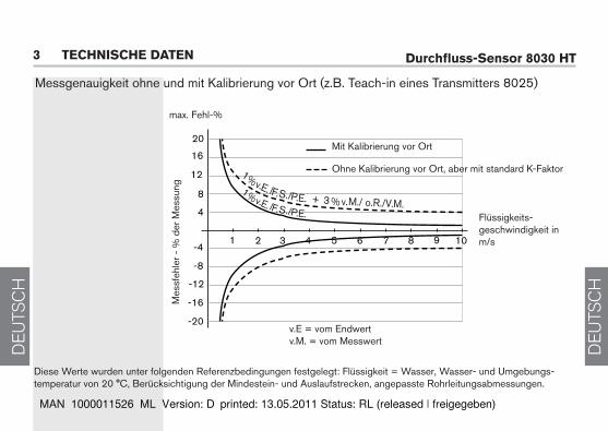
Messgenauigkeit ohne und mit Kalibrierung vor Ort (z.B. Teach-in eines Transmitters 8025)
Mit Kalibrierung vor Ort
Ohne Kalibrierung vor Ort, aber mit standard K-Faktor
Flüssigkeits-geschwindigkeit in m/s
max. Fehl-%
v.E = vom Endwertv.M. = vom Messwert
Mes
sfeh
ler -
% d
er M
essu
ng
Diese Werte wurden unter folgenden Referenzbedingungen festgelegt: Flüssigkeit = Wasser, Wasser- und Umgebungs-temperatur von 20 °C, Berücksichtigung der Mindestein- und Auslaufstrecken, angepasste Rohrleitungsabmessungen.
8030 ht 11
DEU
TSCH
DEU
TSCH
DEU
TSCH
DEU
TSCH
durchfluss-sensor 8030 ht4 installation
4.1 allgemeine hinweise
Überprüfen Sie immer die chemische Kompatibilität der Sensor-Werkstoffe mit denen das Gerät in Kontakt kommt. Für weitere Auskünfte, steht Ihnen Bürkert zur Verfügung.
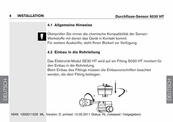
4.2 einbau in die rohrleitung
Das Elektronik-Modul SE30 HT wird auf ein Fitting S030 HT montiert für den Einbau in die Rohrleitung. Beim Einbau des Fittings müssen die Einbauvorschriften beachtet werden, die dem Fitting beiliegen.
1
2
3
8030 ht 13
DEU
TSCH
DEU
TSCH
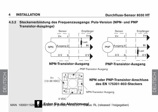
4.3 elektrischer anschlussVergewissern Sie sich stets, dass die Stromversorgung unterbrochen ist, bevor Eingriffe in das Gerät/System vorgenommen werden. Der Stecker muss ausgesteckt sein.Verwenden Sie:- ein geerdetes abgeschirmtes Kabel mit einer dem Prozess entsprechenden Betriebsgrenztemperatur.- Eine Spannungsversorgung guter Qualität (gefiltert und geregelt).obligatorisch ist eine geeignete sicherung für die stromversor-gung zu installieren4.3.1 anschlussstecker en 175301-803 (typ 2508, geliefert)
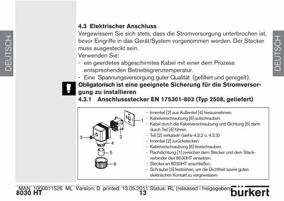
- Innenteil [2] aus Außenteil [4] herausnehmen.- Kabelverschraubung [6] aufschrauben. - Kabel durch die Kabelverschraubung und Dichtung [5] dann durch Teil [4] führen.- Teil [2] verkabeln (siehe 4.3.2 o. 4.3.3)- Innenteil [2] zurückstecken.- Kabelverschraubung [6] festschrauben.- Flachdichtung [1] zwischen dem Stecker und dem Steck- verbinder des 8030HT einsetzen.- Stecker an 8030HT anschließen.- Schraube [3] festziehen, um die Dichtheit sowie guten elektrischen Kontakt zu vergewissern
1
34
5
6
2
DEU
TSCH
DEU
TSCH
durchfluss-sensor 8030 ht
PNP
0 V
V+ V+
IN
0 V
1
4
3
NPN
0 V
V+ V+
IN
0 V
1
2
3
4 installation
npn-transistor-ausgang
Sensor SensorEmpfänger
Last
Empfänger
Last
npn oder pnp-transistor-anschluss des en 175301-803-steckers
V+(12-36 VDC)
NPN-Transistor-Ausgang
0 VDC
AusgangAusgang
4.3.2 steckerverbindung des frequenzausgangs: puls-Version (npn- und pnp transistor-ausgänge)
PNP-Transistor-Ausgang
pnp-transistor-ausgang
erden sie die abschirmung!
1
32
4
8030 ht 15
DEU
TSCH
DEU
TSCH
3
2
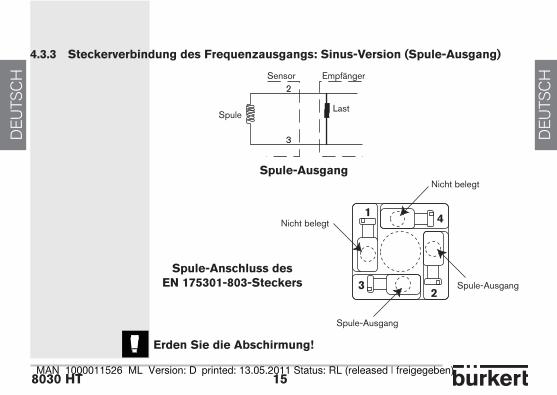
4.3.3 steckerverbindung des frequenzausgangs: sinus-Version (spule-ausgang)
Nicht belegt
Nicht belegt
Spule-Ausgang
Spule-Ausgang
spule-anschluss desen 175301-803-steckers
erden sie die abschirmung!
spule-ausgang
Sensor Empfänger
LastSpule
1
32
4
DEU
TSCH
DEU
TSCH
durchfluss-sensor 8030 ht5 anhang
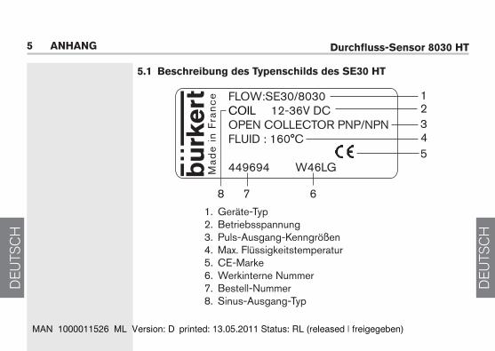
5.1 Beschreibung des typenschilds des se30 ht
1. Geräte-Typ 2. Betriebsspannung 3. Puls-Ausgang-Kenngrößen 4. Max. Flüssigkeitstemperatur 5. CE-Marke 6. Werkinterne Nummer 7. Bestell-Nummer 8. Sinus-Ausgang-Typ
FLOW:SE30/8030COIL 12-36V DCOPEN COLLECTOR PNP/NPNFLUID : 160°C
449694 W46LGMad
e i
n F
ran
ce 1
23
5
7 6
4
8
8030 ht 17
DEU
TSCH
DEU
TSCH
l/min
DN
65
DN
50
(DN
65)*
DN
40
(DN
50)*
DN
32
(DN
40)*
DN
25
(DN
32)*
DN
20
(DN
25)*
DN
15
(DN
20)*
5000
1000 10
0 3 2 120 10 0.55 0.3
0.2
500
50
0.01
0.02
0.050.1
0.2
0.5125102050100
200
m3
/h 0.1
0.3
0.5
12
35
100.
2m
/s
DN
08
DN
06
5.2 durchfluss-dn-flüssigkeitsgeschwindigkeit-diagramme
Durchfluss
Flüs
sigk
eits
gesc
hwin
digk
eit
DN
des
Fitt
ings
* Fü
r fol
gend
e Fi
tting
s:-
Auß
enge
win
de n
ach
SM
S 1
145
- S
chw
eiße
nden
nac
h S
MS
300
8, B
S 4
825
/ A
SM
E B
PE
od
er D
IN 1
850
Rei
he 2
-
Cla
mp
nach
SM
S 3
017
/ IS
O 2
852,
BS
482
5 /
AS
ME
BP
E
oder
DIN
326
76
DEU
TSCH
DEU
TSCH
durchfluss-sensor 8030 htgp
m
1000 50
0
200
20 10 5 2 1 0.5
0.2
0.1
0.05
0.02
0.01
3020
0.3
0.5
12
35
10
DN
65
100
50
fps
DN
08
DN
06
DN
50
(DN
65)*
DN
40
(DN
50)*
DN
32
(DN
40)*
DN
25
(DN
32)*
DN
20
(DN
25)*
DN
15
(DN
20)*
5 anhang
Durchfluss
Flüs
sigk
eits
gesc
hwin
digk
eit
DN
des
Fitt
ings
* Fü
r fol
gend
e Fi
tting
s:-
Auß
enge
win
de n
ach
SM
S 1
145
- S
chw
eiße
nden
nac
h S
MS
300
8, B
S 4
825
/ A
SM
E B
PE
od
er D
IN 1
850
Rei
he 2
-
Cla
mp
nach
SM
S 3
017
/ IS
O 2
852,
BS
482
5 /
AS
ME
BP
E
oder
DIN
326
76
8030 ht 19
DEU
TSCH
DEU
TSCH
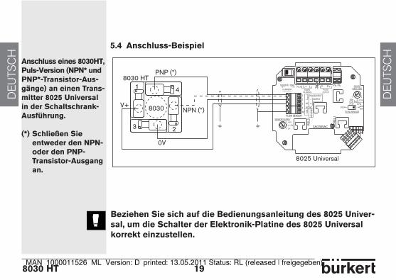
5.4 anschluss-Beispiel
anschluss eines 8030ht, puls-Version (npn* und pnp*-transistor-aus-gänge) an einen trans-mitter 8025 universal in der schaltschrank- ausführung.
(*) schließen sie entweder den npn- oder den pnp- transistor-ausgang an.
Beziehen sie sich auf die Bedienungsanleitung des 8025 univer-sal, um die schalter der elektronik-platine des 8025 universal korrekt einzustellen.
NPN (*)
PNP (*)8030 HT
1
3 2
V+
0V
8030
4
NPN/
PNP
SUPPLY
COIL
1
234
PE
NC
3A/230VAC
RE
L1
RE
L2SENSOR SUPPLY
FLOW SENSOR
COIL NPNPNP
FLOW SENSOR
SOURCE SINK
CURRENTIout L+ L-
Supply13..30Vdc
PEPE PE
NCNC+-
PULSE INPUT
123 L+
+12V
+5V
P- P+PULSE
OUTPUT
SENSORINPUT LOAD
12
339K
NPN470
2.2KCOILPNP
8025 Universal
DEU
TSCH
DEU
TSCH
durchfluss-sensor 8030 ht5 anhang
Manuel utilisateur
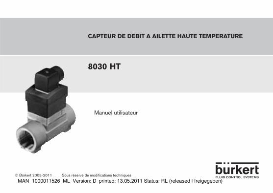
capteur de debit a ailette haute temperature
8030 ht
© Bürkert 2003-2011 Sous réserve de modifications techniques
FRANCAIS
FRANCAIS
capteur de débit 8030 ht
table des matières1ConsignesdeseCurite��������������������������������������������������������������������������������������������������������������������������������4
1.1 Utilisation ..................................................................................................................................................................................................41.2 Précautions lors de l‘installation et la mise en service........................................................................................51.3 Conformité aux normes ................................................................................................................................................................5
2desCription�������������������������������������������������������������������������������������������������������������������������������������������������������������6
2.1 Construction et principe de mesure ...................................................................................................................................62.2 Tableau de commande des modules électroniques SE30 HT .....................................................................72.3 Dimensions (mm) ..............................................................................................................................................................................7
3CaraCteristiquesteChniques��������������������������������������������������������������������������������������������������������������8
4installation���������������������������������������������������������������������������������������������������������������������������������������������������������12
4.1 Recommandations générales ...............................................................................................................................................124.2 Montage sur la conduite ...........................................................................................................................................................12
8030 ht 3
FRANCAIS
FRANCAIS
4.3 Raccordement électrique .........................................................................................................................................................13 4.3.1 Connecteur EN 175301-803 (type 2508, fourni) ..............................................................................13 4.3.2 Câblage de la sortie fréquence :
version impulsion (sorties transistor NPN et PNP) .............................................................................14 4.3.3 Câblage de la sortie fréquence : version sinusoïdale (sortie bobine) ...................................15
5annexes��������������������������������������������������������������������������������������������������������������������������������������������������������������������16
5.1 Description de l’étiquette du capteur SE30 HT ....................................................................................................165.2 Abaques débit-DN-vitesse ....................................................................................................................................................175.3 Exemple de raccordement ......................................................................................................................................................19
FRANCAIS
FRANCAIS
capteur de débit 8030 ht1 consignes de securite
respecter les consignes de sécurité, repérées par le symbole ci-contre, ainsi que toutes les instructions contenues dans ce manuel.
1.1 utilisation
Le capteur 8030 HT est destiné à la mesure du débit dans des liquides neutres ou légèrement agressifs et exempts de particules solides.
Le fabricant décline toute responsabilité pour les dommages dus à une utilisation inadéquate ou non conforme de cet appareil. Toute modification ou transformation annule la garantie applicable à ce produit.
les travaux de montage et/ou de maintenance doivent être réalisés par un personnel qualifié. en cas de difficultés lors de l‘installation ou de la mise en service, veuillez contacter votre fournisseur bürkert dans les plus brefs délais.
8030 ht 5
FRANCAIS
FRANCAIS
1.2 précautions lors de l‘installation et la mise en service
- Veillez toujours à la compatibilité chimique des matériaux en contact avec le fluide à mesurer.- De même, lors du nettoyage de l‘appareil, veillez à utiliser des produits chimiquement compatibles avec les matériaux de l‘appareil. - Protéger l’appareil contre les perturbations électromagnétiques, les rayons ultraviolets et, lorsqu’il est installé à l’extérieur, des effets des conditions climatiques.
lors du démontage du capteur de la conduite, prenez toutes les précautions liées au procédé.
1.3 conformité aux normes
CEM : EN 50081-1, 61000-6-2Sécurité : EN 61010-1Tenue aux vibrations : EN 60068-2-6Tenue aux chocs : EN 60068-2-27
FRANCAIS
FRANCAIS
capteur de débit 8030 ht
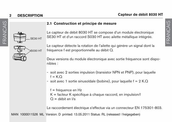
SE30 HT
S030 HT
2.1 construction et principe de mesure
Le capteur de débit 8030 HT se compose d‘un module électronique SE30 HT et d‘un raccord S030 HT avec ailette métallique intégrée.
Le capteur détecte la rotation de l’ailette qui génère un signal dont la fréquence f est proportionnelle au débit Q.
Deux versions du module électronique avec sortie fréquence sont dispo-nibles :
- soit avec 2 sorties impulsion (transistor NPN et PNP), pour laquelle f = K.Q- soit avec 1 sortie sinusoïdale (bobine), pour laquelle f = 2 K.Q
f = fréquence en Hz K = facteur K spécifique à chaque raccord, en impulsion/l Q = débit en l/s
Le raccordement électrique s‘effectue via un connecteur EN 175301-803.
2 description
8030 ht 7
FRANCAIS
FRANCAIS
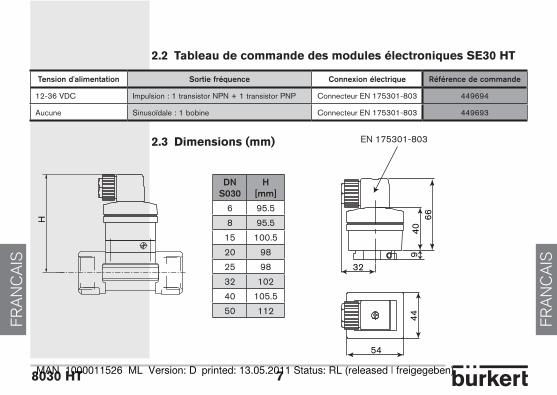
2.2 tableau de commande des modules électroniques se30 ht
2.3 dimensions (mm)
tensiond'alimentation sortiefréquence Connexionélectrique référencedecommande
12-36 VDC Impulsion : 1 transistor NPN + 1 transistor PNP Connecteur EN 175301-803 449694
Aucune Sinusoïdale : 1 bobine Connecteur EN 175301-803 449693
dns030
h[mm]
6 95.5
8 95.5
15 100.5
20 98
25 98
32 102
40 105.5
50 112
32
4066
44
54
9
EN 175301-803
H
FRANCAIS
FRANCAIS
capteur de débit 8030 ht
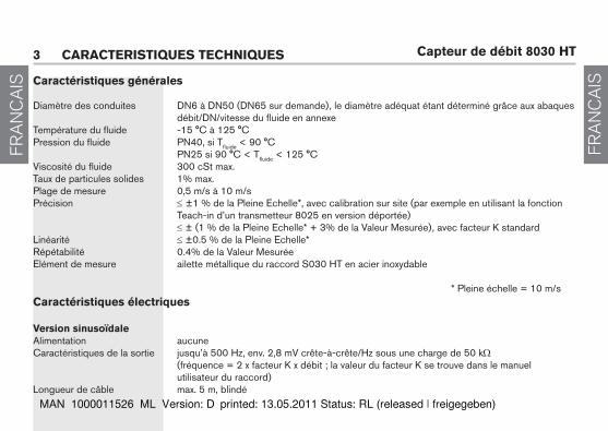
caractéristiques générales
Diamètre des conduites DN6 à DN50 (DN65 sur demande), le diamètre adéquat étant déterminé grâce aux abaques débit/DN/vitesse du fluide en annexeTempérature du fluide -15 °C à 125 °CPression du fluide PN40, si Tfluide < 90 °C PN25 si 90 °C < Tfluide < 125 °C Viscosité du fluide 300 cSt max.Taux de particules solides 1% max.Plage de mesure 0,5 m/s à 10 m/sPrécision ≤ ±1 % de la Pleine Echelle*, avec calibration sur site (par exemple en utilisant la fonction Teach-in d’un transmetteur 8025 en version déportée) ≤ ± (1 % de la Pleine Echelle* + 3% de la Valeur Mesurée), avec facteur K standardLinéarité ≤ ±0.5 % de la Pleine Echelle*Répétabilité 0.4% de la Valeur Mesurée Elément de mesure ailette métallique du raccord S030 HT en acier inoxydable
* Pleine échelle = 10 m/scaractéristiques électriques
Version sinusoïdaleAlimentation aucuneCaractéristiques de la sortie jusqu’à 500 Hz, env. 2,8 mV crête-à-crête/Hz sous une charge de 50 kW (fréquence = 2 x facteur K x débit ; la valeur du facteur K se trouve dans le manuel utilisateur du raccord)Longueur de câble max. 5 m, blindé
3 caracteristiques techniques
8030 ht 9
FRANCAIS
FRANCAIS
Version impulsionAlimentation 12-36 VDC, filtrée et réguléeConsommation ≤ 10 mA (sans charge)Protection contre l‘inversion de polarité ouiCaractéristiques des sorties transistor NPN et PNP, collecteur ouvert, 700 mA max., sortie NPN : 0,2-30 VDC et sortie PNP : tension d’alimentation (voir exemple en Annexe) fréquence jusqu’à 250 Hz (fréquence = facteur K x débit ; la valeur du facteur K se trouve dans le manuel utilisateur du raccord)Protection contre les courts-circuits ouiLongueur de câble max. 50 m, blindé (jusqu’à 500 m en fonction de l’impédance du câble et la consommation)
raccordement électriqueToutes versions Connecteur EN 175301-803 (type 2508, fourni)Type de câble recommandé blindé, section comprise entre 0,14 et 0,5 mm2
matériauxBoîtier / Presse-étoupe PPS renforcé en fibres de verre / PARaccord S030 HT, ailette acier inoxydablePaliers du raccord S030 HT IglidurJoint / axe raccord S030 HT FKM / céramiqueenvironnementTempérature ambiante - version impulsion : -15 à +80° C(fonctionnement et stockage) - version sinusoïdale : -15 à +100° CHumidité relative < 80%, non condenséeClasse de protection du boîtier IP 65 avec connecteur enfiché et serré
FRANCAIS
FRANCAIS
capteur de débit 8030 ht3 caracteristiques techniques
Précision de la mesure avec (fonction Teach-in d’un transmetteur 8025 par exemple) et sans calibration sur site
Avec calibration sur site
Avec facteur K standard (sans calibration sur site)
Vitesse du fluide en m/s
% d’erreur max.
P.E = Pleine EchelleV.M. = Valeur Mesurée
Err
eur d
e m
esur
e -
% d
e la
mes
ure
Ces valeurs ont été déterminées dans les conditions de référence suivantes : fluide = eau, températures du fluide et ambiante = 20 °C, distances amont et aval respectées, dimensions des conduites adaptées.
1 92 3 4 5 6 7 8 10
4
8
20
-4
-8
-12
-16
-20
1v.
%
+ 3P.E. S./F. / E. v.% M./ o.R./V.M.
1v.
%
P.E. S./F. / E.
16
12
8030 ht 11
FRANCAIS
FRANCAIS
FRANCAIS
FRANCAIS
capteur de débit 8030 ht4 installation
4.1 recommandations générales
Vérifier systématiquement la compatibilité chimique des matériaux com-posants le capteur et les produits susceptibles d’entrer en contact avec celui-ci.Votre fournisseur Bürkert reste à votre entière disposition pour tous ren-seignements complémentaires.
4.2 montage sur la conduite
Le module électronique SE30 HT est associé à un raccord S030 HT qui permet son installation sur une conduite. Lors du montage, respecter les consignes livrées avec le raccord S030 HT.
1
2
3
8030 ht 13
FRANCAIS
FRANCAIS
4.3 raccordement électriqueAssurez-vous toujours que l‘appareil est hors tension avant d‘effectuer toute intervention. Le connecteur doit être débranché.Utilisez :- un câble blindé relié à la terre avec une température limite de service adaptée au process.- une alimentation de qualité (filtrée et régulée).utiliser impérativement un fusible correctement dimensionné pour l‘alimentation.
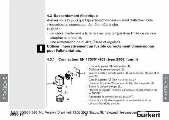
4.3.1 connecteur en 175301-803 (type 2508, fourni)
1
34
5
6
2
- Extraire la partie [2] de la partie [4].- Dévisser le presse-étoupe [6]. - Insérer le câble dans la partie [4] via le presse-étoupe et le joint [5].- Câbler la partie [2] (voir 4.3.2 ou 4.3.3)- Replacer la partie [2] une fois câblée, dans la partie [4].- Serrer le presse-étoupe [6].- Placer le joint plat [1] entre le connecteur et son embase sur le 8030HT.- Raccorder le connecteur au 8030HT.- Serrer la vis [3] afin de garantir une étanchéité et un contact électrique correct
FRANCAIS
FRANCAIS
capteur de débit 8030 ht
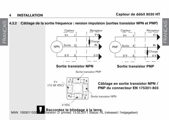
NPN
0 V
V+ V+
IN
0 V
1
2
3
PNP
0 V
V+ V+
IN
0 V
1
4
3
1
32
4
4.3.2 câblage de la sortie fréquence : version impulsion (sorties transistor npn et pnp)
4 installation
sortie transistor npn sortie transistor pnp
Capteur CapteurRécepteur
Charge
Récepteur
Charge
câblage en sortie transistor npn / pnp du connecteur en 175301-803
V+(12-36 VDC)
Sortie transistor NPN
0 VDC
SortieSortie
Sortie transistor PNP
raccordez le blindage à la terre.
8030 ht 15
FRANCAIS
FRANCAIS
3
2
1
32
4
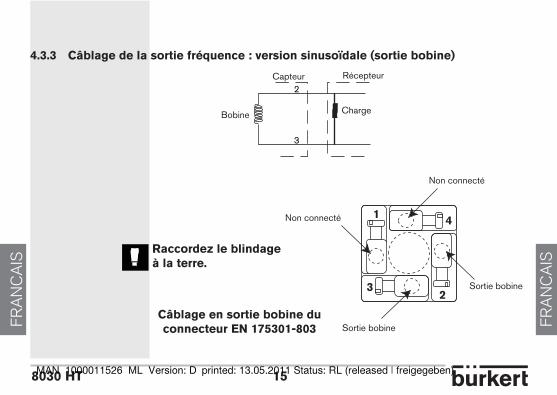
4.3.3 câblage de la sortie fréquence : version sinusoïdale (sortie bobine)
câblage en sortie bobine du connecteur en 175301-803
Non connecté
Sortie bobine
Non connecté
Sortie bobine
Capteur Récepteur
ChargeBobine
raccordez le blindage à la terre.
FRANCAIS
FRANCAIS
capteur de débit 8030 ht5 annexes
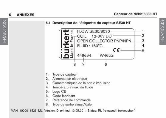
5.1 description de l’étiquette du capteur se30 ht
1. Type de capteur2. Alimentation électrique3. Caractéristiques de la sortie impulsion4. Température max. du fluide 5. Logo CE6. Code fabricant7. Référence de commande8. Type de sortie sinusoïdale
FLOW:SE30/8030COIL 12-36V DCOPEN COLLECTOR PNP/NPNFLUID : 160°C
449694 W46LGMad
e i
n F
ran
ce 1
23
5
7 6
4
8
8030 ht 17
FRANCAIS
FRANCAIS
l/min
DN
65
DN
50
(DN
65)*
DN
40
(DN
50)*
DN
32
(DN
40)*
DN
25
(DN
32)*
DN
20
(DN
25)*
DN
15
(DN
20)*
5000
1000 10
0 3 2 120 10 0.55 0.3
0.2
500
50
0.01
0.02
0.050.1
0.2
0.5125102050100
200
m3
/h 0.1
0.3
0.5
12
35
100.
2m
/s
DN
08
DN
06
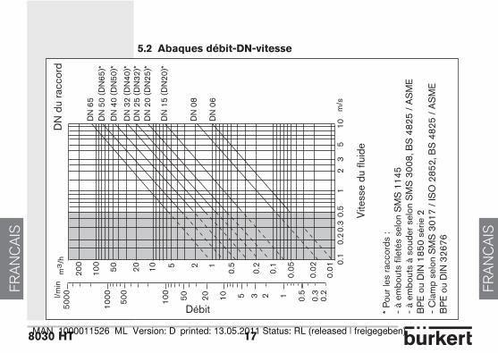
5.2 abaques débit-dn-vitesse
Débit
DN
du
racc
ord
Vite
sse
du fl
uide
* P
our l
es ra
ccor
ds :
- à
embo
uts
filet
és s
elon
SM
S 1
145
- à
embo
uts
à so
uder
sel
on S
MS
300
8, B
S 4
825
/ A
SM
E
BP
E o
u D
IN 1
850
série
2
- C
lam
p se
lon
SM
S 3
017
/ IS
O 2
852,
BS
482
5 /
AS
ME
B
PE
ou
DIN
326
76
FRANCAIS
FRANCAIS
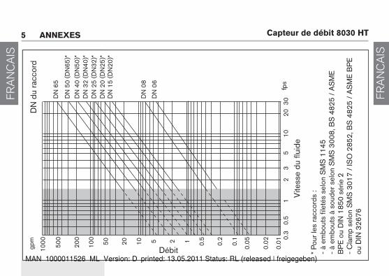
capteur de débit 8030 htgp
m
1000 50
0
200
20 10 5 2 1 0.5
0.2
0.1
0.05
0.02
0.01
3020
0.3
0.5
12
35
10
DN
65
100
50
fps
DN
08
DN
06
DN
50
(DN
65)*
DN
40
(DN
50)*
DN
32
(DN
40)*
DN
25
(DN
32)*
DN
20
(DN
25)*
DN
15
(DN
20)*
5 annexes
Débit
DN
du
racc
ord
Vite
sse
du fl
uide
* P
our l
es ra
ccor
ds :
- à
embo
uts
filet
és s
elon
SM
S 1
145
- à
embo
uts
à so
uder
sel
on S
MS
300
8, B
S 4
825
/ A
SM
E
BP
E o
u D
IN 1
850
série
2
- C
lam
p se
lon
SM
S 3
017
/ IS
O 2
852,
BS
482
5 /
AS
ME
BP
E
ou D
IN 3
2676
8030 ht 19
FRANCAIS
FRANCAIS
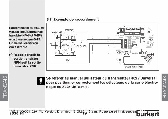
5.3 exemple de raccordement
raccordement du 8030 ht, version impulsion (sorties transistor npn* et pnp*) à un transmetteur 8025 universal en version encastrable.
(*) raccorder soit la sortie transistor npn soit la sortie transistor pnp.
se référer au manuel utilisateur du transmetteur 8025 universal pour positionner correctement les sélecteurs de la carte électro-nique du 8025 universal.
NPN (*)
PNP (*)8030 HT
1
3 2
V+
0V
8030
4
NPN/
PNP
SUPPLY
COIL
1
234
PE
NC
3A/230VAC
RE
L1
RE
L2SENSOR SUPPLY
FLOW SENSOR
COIL NPNPNP
FLOW SENSOR
SOURCE SINK
CURRENTIout L+ L-
Supply13..30Vdc
PEPE PE
NCNC+-
PULSE INPUT
123 L+
+12V
+5V
P- P+PULSE
OUTPUT
SENSORINPUT LOAD
12
339K
NPN470
2.2KCOILPNP
8025 Universal

FRANCAIS
FRANCAIS
capteur de débit 8030 ht5 annexes
Pneutrol International Limited Unit 173 Argyle Industrial Estate, Argyle Street, Nechells, Birmingham B7 5TE
www.pneutrolfluidcontrol.com [email protected] Tel: +44 (0) 1213287288


![PEMD12; PUMD12 NPN/PNP resistor-equipped transistors; R1 ... · NPN/PNP resistor-equipped transistors; R1 = 47 k , R2 = 47 k 5. Limiting values Table 6. Limiting values [1] Device](https://img.pdfslide.us/doc/110x75/5f6af1de5184727ecd25db58/pemd12-pumd12-npnpnp-resistor-equipped-transistors-r1-npnpnp-resistor-equipped.jpg)