Embed Size (px)
Citation preview

k D-ASAS. 802 ARMYRENGINEER WATERWA YS EXPERIMENT STATION VICKSBURG--ETC FG1/
OLD RIE VRAK STRUCTURE OUTLET MODIFICATIONS; HYDRAULIC MO -ETC(U)
OCT 80 R R COPELANDUNCLASSIFIED WES/MP/H4-8O-5 NL
ONE

[uwLEVEL;MISCELLANEOUS PAPER HL-80-5
OLD RIVER OVERBANK STRUCTUREOUTLET MODIFICATIONS DTIC
Hydraulic Model Investigation ELE CTEby DEC 111980
Ronald R. Copeland SHydraulics Laboratory
U. S. Army Engineer Waterways Experiment Station0 P. O. Box 631, Vicksburg, Miss. 39180
MOctober 1980Rnal Report
[Appo For Pubic R,. ee. ; Di U,,tO U i
"w -t
;'I
row for U. S. Army Engineer District, New OrleansNew Odom, La. 70160
80 1210 001

Destroy this report when no longer needed. Do not returnit to the originator.
The findings in this report are not to be construed as an officialDepartment of the Army position unless so designated
by other authorized documents.
L A

SUn:! 1as-qi fi Pd
SECURITY CLASSIFICATION OF THIS PAGE (Whan Dati Entere_)
REPORT DOUENTATION PAGE READ 'STRUCTIONS
PAGE BEFORE COMPLETING FORM1. REPORT NUMBER II. GOVT ACCESSION No. 3. RECIPIENT'S CATALOG NUMBER
Miscellaneous Paper HL-80-5 0V/) '' . .,.
4. TITLE (and Subtitle) S. TYPE OF REPORT & PERIOD COVErRED
"OLDIVER OVERBANK STRUCTURE OUTLET -/Final repit "ODITICATfDNS;nHydraulic Model •Investigation. 4'
7. AUTHOOR 1 fan
Ronald R./Copeland
9. PERFORMING ORGANIZATION NAME AND ADDRESS 10. PROGRAM ELEMENT. PROJECT, TASK
U. S. Army Engineer Waterways Experiment Station AREA & WORK UNIT NUMBERS
Hydraulics LaboratoryP. 0. Box 631, Vicksburg, Miss. 39180
II. CONTROLLING OFFICE NAME AND ADDRESS it. p0 POtT-AT-U. S. Army Engineer District, New Orleans t 0
P. 0. Box 60267 -V W AGESNew Orleans, La. 70160 24 1 -
14. MONITORING AGENCY NAME & ADDRESS(Itf different from Controii4 Office) IS. SECURITY CLASS. (of this report)
UnclassifiedIS.. DECL ASSI FI CATION/DOWNGRADING
SCHEDU LE
Is. DISTRIBUTION STATEMENT (of thie Report)
Approved for public release; distribution unlimited.
17. DISTRIBUTION STATEMENT (of the abstract entered In Block 20, If different from Report)
1S. SUPPLEMENTARY NOTES
19. KEY WORDS (Continue on reveree elde It necesosary and Identify by block number)
*GabionsHydraulic modelsOld River Overbank Control structureOutlet worksOverbank flow
1 20 ABSTRACT (Cmebe ism reverse ebb N necneey and Identify by block nmber)
ISix different outlet modification designs for the Old River Overbank ControlStructure were evaluated. Model tests were conducted on five of the designsand design variations. A 1:24-scale section model was used to simulate dis-charges up to 550,000 cfs. Type 5 outlet modification design, utilizing ga-bions placed parallel to the flow on a IV on 1OH slope, was deemed the bestof the six designs tested. Recommendations were also made to increase gabioneffectiveness by improved construction and placement methods.
DO roo 1473 EviTion OF I Nov is OBSOLETEJAN 73"n IA~iF
SECURITY CLAS&iFICATION OF THIS PACE (Whon Data Entered
,L.f /: y
!i
. ..4 L_ .... ... ..i i• .... ." 1 I ' I .......I ' I 1il l i .. .. i I Ill I ]i I I I

Preface
The model investigation reported herein was requested and author-
ized by the U. S. Army Engineer District, New Orleans (LMN), in June
1979. The study was conducted during the period August 1979 to November
1979 in the Hydraulics Laboratory of the U. S. Army Engineer Waterways
Experiment Station (WES) under the direction of Mr. H. B. Simmons, Chief
of the Hydraulics Laboratory, and under the general supervision of Messrs.
J. L. Grace, Jr., Chief of the Hydraulic Structures Division, and N. R.
Oswalt, Chief of the Spillways and Channels Branch. The project engineer
for the model study was Mr. R. R. Copeland, assisted by Mr. E. L.
Jefferson. This report was prepared by Mr. Copeland.
Commander and Director of WES during the conduct of the study and
the preparation and publication of this report was COL Nelson P. Conover,
CE. Technical Director was Mr. F. R. Brown.
Access;c:i orNTIS . --
DDC L L
By__
Di 3tri ......
____ Thdes
A;a 11L.,d/orDist special
i'

Contents
Page
Preface ........... ............................. . ..
Conversion Factors, U. S. Customary toMetric (SI) Units of Measurement .... .................. 3
Introduction .......... ............................. 4
I Outlet Modification Tests ........ ....................... 5
Type 1 ............. .......................... 5Type 2 ............. .......................... 6Type 3 ............. .......................... 6Type 4 ............. .......................... 7Type 5 ............. .......................... 7Type 6 ............. ......................... 7Type 5 with gabion variation ....... ............... 7
Test Data .............. ............................ 8
Discussion and Conclusions ......... ................... 8
Photos 1-8
Plates 1-7
2i
'I

Conversion Factors, U. S. Customary to
Metric (SI) Units of Measurement
U. S. customary units of measurement used in this report can be con-
verted to metric (SI) units as follows:
Multiply By To Obtain
cubic feet per second 0.02831685 cubic metres persecond
feet 0.3048 metres
inches 0.0254 metres
miles (U.S. statute) 1609.347 metres
pounds (mass) 0.4535924 kilograms
4 3

OLD RIVER OVERBANK STRUCTURE OUTLET MODIFICATIONS
Hydraulic Model Investigation
Introduction
1. Model tests of alternative designs for the proposed modifica-
tion of the Old River Overbank Structure Outlet were conducted at the
U. S. Army Engineer Waterways Experiment Station from August through
November 1979. The Old River Control Structures are located on the west
bank of the Mississippi River approximately 50 miles* northwest of Baton
Rouge, La., and approximately 35 miles southwest of Natchez, Miss.
(Figure 1). A 1:24-scale section model was used to investigate and
compare the hydraulic performance of each of the six different outlet
OVERSANKCONTROL srRuCTv' "
MODIFICATION TOOVERFLOW OUTLET
.. . . . . . . ...... ....... / ,, ,
OUTFLOC c. .. E,
LO-. SLL CONTROL STRUCTURE
~Figure 1. Vicinity map
JJ
*A table of factors for converting U. S. customary units of measure-
AA L'!'i ment to metric (SI) units is presented on page 3.
I4

modifications shown in Plates 1-4. This two-dimensional model neglected
the effect of crosscurrents and eddies that will occur across the
prototype structure and the probable unequal flow distribution on the
structure due to the asymmetry of the approach channel.
2. The prototype discharges and tailwaters that were simulated
in the section model are tabulated below:
TailwaterElevation
Discharge, cfs ft msl*
42,000 33.678,000 35.7
122,000 37.8174,000 40.0230,000 42.2246,000 45.0258,000 46.1
320,000 50.7350,000 36.7400,000 40.3450,000 42.9500,000 45.3550,000 47.5
The discharge values shown correspond to those over a total structure
width of 3400 ft. The section model simulated only a 60-ft width of
the proposed uncontrolled spillway. Total discharges of 350,000 cfs and
greater would occur only if the Old River Low Sill Control Structure
was closed and the entire flow was passed through the Old River Overbank
Control Structure. Under such adverse conditions the discharge and
tailwater in the Low Sill Outlet Channel would be significantly reduced
relative to normal conditions.
Outlet Modification Tests
Type I
3. The original design (Type 1) outlet modification proposed
consisted of a concrete spillway extending from a crest at el 42 down a
* All elevations (el) cited herein are in feet referred to mean sea
level.
5

iV-on-20H slope to el 35 (Plate 1). The gradation of the proposed up-
stream and downstream rock riprap is shown in Plate 5. The Type 1 out-
let modification contained a hydraulic jump on the concrete slab for
only one of the designated test conditions, 320,000 cfs. All other test
conditions resulted in failure of the riprap downstream of the slab.
4. Additional tests of the Type 1 outlet modification were con-
ducted to determine the length of the concrete slab necessary for riprap
stability. A slab extension of 150 ft down to el 27.6 was found to be
satisfactory for discharges of 320,000 cfs and less. The riprap failed
for discharges greater than 320,000 cfs. No further concrete slab ex-
tensions were tested because the U. S. Army Engineer District, New
Orleans (LMN), determined that economic and foundation considerations
would eliminate any additional slab extension as a feasible solution.
Type 2
5. The Type 2 outlet modification consisted of a concrete slab
from the crest at el 42 down a iV-on-20H slope to el 35 and gabions
between el 35 and el 27.6 (Plate 2). Gabions 12 ft long, 3 ft wide,
and 1 ft thick with wire openings of 1.33 in. were simulated in the
model. The model gabion baskets were made of standard aluminum screen
and filled with crushed rock passing and retained on No. 4 and No. 8
sieves, respectively. The gabions were oriented with their longitudinal
axes parallel to the flow. The test indicated that the gabions would be
stable; however, the riprap downstream of the gabions failed at dis-
charges greater than 320,000 cfs.
Type 3
6. The Type 3 outlet modification consisted of a gabion spillway
extending from 60 ft upstream of the crest at el 42 down a iV-on-20H
slope to el 27.6 (Plate 2). The gabions were oriented with their lon-
gitudinal axes parallel to the flow. With discharges at 320,000 cfs
and less, a hydraulic jump was satisfactorily contained on the gabion
structure. However, discharges between 350,000 cfs and 500,000 cfs
caused the riprap downstream of the gabions to fail. The riprap was
stable with a discharge of 550,000 cis and tailwater elevation of 47.5.4 6

Type 4
7. The Type 4 outlet modification (Plate 3) consisted only of
riprap and was not tested after it was determined that supercritical
flow conditions would occur on the spillway itself, resulting in failure
of the riprap with the expected tailwaters. Computations also showed
that supercritical flow conditions would exist even if the slope was
reduced to 1V on 40H.
Type 5
8. The Type 5 outlet modification as shown in Photo 1 and Plate 4
provides gabion protection on a iV-on-lOH slope from el 42 to el 20. As
with Type 2 and Type 3 outlet modifications, the gabions were oriented
with their longitudinal axes parallel to the flow. In the prototype,
slope protection will be provided by articulated concrete mattresses
downstream of the gabion structure. The mattresses were not simulated
in the model. This design was stable for all the expected flow condi-
tions, some of which are shown in Photos 2-7.
Type 6
9. The Type 6 outlet modification had the same geometry as Type 5
(Plate 4); however, the gabions were rearranged so that the longitudinal
axes were perpendicular to the flow. During initial testing, severe
failure of the gabion structure occurred at a discharge of 550,000 cfs
as shown in Photo 8. However, this failure did not occur when a second
series of tests were run. The failure is attributed to a slight mis-
alignment of the gabions that occurred during placement in the model or
by settling of the gabions due to inadequate subsurface drainage and re-
sulting hydrostatic pressure developed during the testing. The same
dramatic failure was repeated when one of the gabions was removed
manually from the model.
Type 5 with gabion variation
10. The stability of the Type 5 outlet modification was tested
under similar conditions. When one gabion was removed, the failure
proceeded in a much slower manner and was not as severe. The gabion
failure did not proceed upstream as it did with the Type 6 design, and
the gabions adjacent to the failure tended to sink into the developing
7
-- - iii r . . . I I I . .. .... i ii i .... .i i i ii . ... .i

hole, adding a degree of protection for the rest of the structure. It
is noted that the individual size of gabions simulated in the model
(12 ft by 3 ft by 1 ft) was smaller and easier to displace than the
actual size of prototype gabions (99 ft by 6 ft by 1 ft) that will be
also wired or tied together. Therefore, it is considered that the
stability indicated by the model is conservative.
Test Data
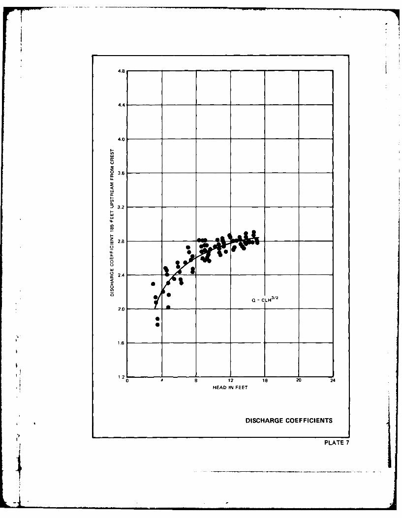
11. The hydraulic characteristics of each type of outlet modi-
fication were determined during the tests. Water-surface elevations
measured 185 ft upstream of the crest were similar for all types and
are shown in Plate 6. Discharge coefficients applicable to the broad-
crested weir equation determined from these data are shown in Plate 7.
Discussion and Conclusions
12. The Type 5 outlet modification was the best design tested.
The model tests demonstrated the importance of quality construction to
ensure proper placement and tying together of the gabions, as irregular
surfaces tend to cause failure of the structure. The gradation and size
of stone placed in the gabion baskets should be uniform and large enough
to prevent individual pieces from being washed through the wire mesh.
Sufficient bedding and filter material should be placed between the soil
foundation and the gabions to provide adequate subsurface drainage with-
out leaching of the soil or the bedding and filter materials through the
relatively thin mattress type of protection. The stability of the
gabions may be improved by increasing the thickness and length of the
gabions. However, it is considered that the larger, interconnected
gabions planned for the proposed structure will be stable under all
expected conditions.
13. Although the size and mesh of the aluminum wire screen used
to construct the model gabions is considered significantly different
from that of the prototype, the relatively greater flexibility of the4 8

prototype gabion baskets allows for increased interlocking with adjacent
baskets and for easier settling into areas such as the downstream toe
of the structure should scour occur. Unknown factors include the dura-
bility and the duration that the wire mesh can resist weathering, abra-
sion, acts of vandalism, etc. However, gabion constructed channel con-
trol structures designed by the U. S. Army Engineer District, St. Paul
(NCS), Office have performed satisfactorily for a number of years in the
Souris River above Minot, N. Dak. Personnel of the U. S. Army Engineer
District, New Orleans, visited and discussed these structures with
personnel of NCS to make full use of the design principles and the
satisfactory experiences gained to date.
bC
4

Photo 1. Outlet modifications, Type 5 design

'44
If,
4
C4i
0

'4FlbS
4-4
04
cn
E-4
AA
0w

4-4
0
C'4
L4)
WH

44
C
00
414

fill /f~
CY
c'-4
4W-

NOWi
cn
4-4
Mid,
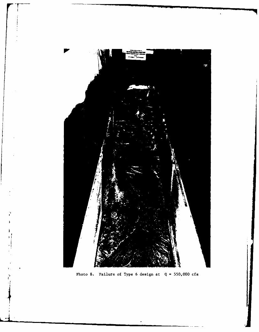
.7Photo 8. Failure of Type 6 design at Q =550,000 cfs

U',
0
CId
0C 0
- cc
02
Z 0.(~~.)Icc
LL
Cd)
g" <Lac Z cc
>. 1
=t41c
I I
9SL JdNI1A1
>LT

I.-
0 8 > A
ILI0. a0
crr
o 0 0
u ?t; -Z L U
M ~ 0IL) C.
C U C4' LU
0.
8-8
CY O- l 0
*~SY 1:1~ u NOIJ-VA313
PLATE 2
6LL

m0 a
0
UL
Li.U
wa: a:
a- ~LL
% w,
IS I INIIA1
PLATE 3

n zn
m- 0
U
LU '--8->
4x, 0 L
0 0
00
2c4Q
cnwc
C.
I-8
ISVJ Li 'NO I.LVA3-13
4LT

4cc
_ _ _ _j_
-Jj
0 00I-.-
0 0______ ____0
a9
(n8
1000
14e4
.LH0~M S ~±OI~.LN38~dPLATE 5

60
58
56LL
(0
0 54
LL
44
52 52
C-
wj 0
Ln
40 10
AAE
m 48
w
46
42
0 100 200 300 400 500 600
DISCHARGE X 1000 CFS
WATER-SURFACE ELEVATIONS
* PLATE 6
4.8
4.4
4.0
U-w
cc 3.6LLI-
o 3.2
to
CL
24
wLL
UC
2.02.8
1.2 3.2
I-
LA.
I-
C-)
2.0
1.l0~ ~ 8 12L1620 2
HEAD IN FEET
DISCHARGE COEFFICIENTS
___ PLATE 7

In accordance with letter from DAEN-RDC, DAEN-ASI dated22 July 1977, Subject: Facsimile Catalog Cards forLaboratory Technical Publications, a facsimile catalogcard in Library of Congress MARC format is reproducedbelow.
Copeland, Ronald ROld River Overbank Structure outlet modifications;
hydraulic model investigation / by Ronald R. Copeland.Vicksburg, Miss. : U. S. Waterways Experiment Station;Springfield, Va. ; available from National TechnicalInformation Service, 1980.9, [8] p., [4] leaves of plates: ill. ; 27 cm. (Miscellaneous
paper - U. S. Army Engineer Waterways Experiment StationHL-80-5)
Prepared for U. S. Army Engineer District, New Orleans,New Orleans, La.
1. Gabions. 2. Hydraulic models. 3. Old River OverbankControl Structure. 4. Outlet works. 5. Overbank flow.I. United States. Army. Corps of Engineers. New OrleansDistrict. II. Series: United States. Waterways ExperimentStation, Vicksburg, Miss. Miscellaneous paperHL-80-5.TA7.W34m no.HL-80-5
bI
*1
--I ... 1