Embed Size (px)
Citation preview

BLINDOCOMPATTO BLINDOS 800A - 5.000A
BX-EBX-RBX-F
IP 68
RESIST FUEGO
IP 55IP 65
DELETEC, S.L. - POGLIANO BUSBAR
1
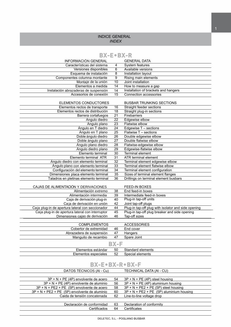
INDICE GENERALINDEX
INFORMACIÓN GENERAL GENERAL DATA Características del sistema 4 System features Versiones disponibles 6 Available versions Esquema de instalación 8 Installation layout Componentes columna montante 9 Rising main elements Montaje de la unión 10 Joint installation Elementos a medida 14 How to measure a gap Instalación abrazaderas de suspensión 14 Installation of brackets and hangers Accesorios de conexión 15 Connection accessories
ELEMENTOS CONDUCTORES BUSBAR TRUNKING SECTIONS Elementos rectos de transporte 16 Straight feeder sections Elementos rectos de distribución 18 Straight plug-in sections Barrera cortafuegos 21 Firebarriers Ángulo diedro 22 Edgewise elbow Ángulo plano 23 Flatwise elbow Ángulo en T diedro 24 Edgewise T – sections Ángulo en T plano 25 Flatwise T – sections Doble ángulo diedro 26 Double edgewise elbow Dobleángulo Double27plano flatwiseelbow Ángulo plano diedro 28 Flatwise-edgewise elbow Ángulodiedro Edgewise-flatwise29plano elbow Elemento terminal 30 Terminal element Elemento terminal ATR 31 ATR terminal element Ángulo diedro con elemento terminal 32 Terminal element edgewise elbow Á ngulo planocon elemento Terminal33 terminal elementflatwiseelbow Configuración del elemento terminal Terminal34 elementconfiguration Dimensiones placaelemento terminal Sizes35 ofterminalelementflanges Taladros en pletinas elemento terminal 36 Drillings on terminal element busbars
CAJAS DE ALIMENTACIÓN Y DERIVACIONES FEED-IN BOXES Alimentación extremo 38 End feed-in boxes Alimentación intermedia 39 Caja de derivación plug-in 40 Ca ja de derivación en unión 42 Joint tap-off plugs Ca ja plug-in de apertura lateral con seccionador 44 Plug-in tap-off plug with isolator and side opening Ca ja plug-in de apertura lateral con interruptor 45 Plug-in tap-off plug breaker and side opening Dimensiones cajas de derivación 46 Tap-off sizes COMPLEMENTOS ACCESSORIES Cobertor de extremidad 46 End cover Abrazadera de suspensión 47 Hangers Manguito de recambio 47 Spare Joint
Elementos estándar 50 Standard elements Elementos especiales 52 Special elements
DATOS TÉCNICOS (Al - Cu) TECHNICAL DATA (Al - CU) 3P + N + PE (4P) envolvente de acero 54 3P + N + PE (4P) steel housing 3P + N + PE (4P) envolvente de aluminio 56 3P + N + PE (4P) aluminium housing 3P + N + PE2 + PE (5P) envolvente de acero 58 3P + N + PE2 + PE (5P) steel housing 3P + N + PE2 + PE (5P) envolvente de aluminio 60 3P + N + PE2 + PE (5P) aluminium housing Caida de tensión concatenada 62 Line-to-line voltage drop
Declaración de conformidad 63 Declaration of conformity Certificates64Certificados
BX-E•BX-R
BX-F
BX-E•BX-R•BX-F
Intermediate feed-in boxesPlug-in tap-off units
BX-E
2
POGLIANO BUSBARDELETEC, S.L. -

3
POGLIANO BUSBARDELETEC, S.L. -

BX-E • BX-R4
INFORMACIÓN GENERALGENERAL INFORMATION
CARACTERÍSTICAS COMUNES DEL SISTEMA BLINDOCOMPATTO ®
BLINDOCOMPATTO® SYSTEM FEATURES
Conformidad con las normas nacionales e internacionales:CEI EN 61439-6, EN61439-6IEC 61439-6
Conductores desde 800 A hasta 6300 A 3P+N+PE adecuadospara el transporte y distribución de energia eléctrica en trazados verticales y horizontales de cualquier posición.Versiones disponibles: Ver páginas 4-5.
Dimensiones muy pequeñas, elevada resistencia a los esfuerzos electrodinámicos, baja impedancia, baja caída de tensión, óptima resistencia a las agresiones de los agentes atmosféricos, hacen del BX-E/R adecuado para su instalación en espacios reducidos yambientes difíciles.
Tensiones de empleo hasta 1000 V a la frecuencia de 50/60 Hz.
Envolvente prelacada color RAL 7032 de 1,5 mm de espesor.
Pletinas conductoras en cobre electrolítico al 99,9% o en aleaciónde aluminio tratadas galvánicamente y estañadas en toda su longitud.
Rapidez y facilidad de instalación gracias al manguito monoblock con doble cabeza de rotura (60 Nm).
Las pletinas se ensamblan de manera compacta sin soportesaislantes. Esta configuración reduce al mínimo los valores dereactancia. Gracias a las amplias secciones de conductor de fase, los valores de resistencia son así mismo muy reducidos. Consecuentemente, la impedancia del BX-E y BX-R es muy baja.
Las bajas pérdidas por efecto Joule contribuyen al ahorroenergético (ver tablas técnicas).
Óptima disipación del calor a través de la superficie de la envolvente.
Suspensión rápida con elevada soportación de cargas mecánicas.
Complies to international and domestic standards:CEI EN 61439-6, EN 61439-6, IEC 61439-6 and all national standards deriving from them.
Rated current from 800 up to 6300 A 3P+N+PE. Feeder or plug-in lines with horizontal or vertical sections, straight or bent.Available versions see page 4-5.
Very compact size, high short-circuit strength, low impedance, low voltage drop and good corrosion strength make BX-E/R system suitable for installation in small spaces and difficult environments.
Voltage up to 1000V at frequencies of 50/60 HZ
Painted RAL 7032 thickness: 1.5 mm.
Busbars: pure electrolytic copper (99.9%) or aluminium busbars, zinc-plated, copper-plated and tin-plated throughout their length.
Speedy and easy installation, also thanks to the monobloc joint with double head bolt (60 Nm).
The busbars are assembled sandwich-type with no supports. This configuration minimizes reactance. Thanks to abundant phase cross sections, resistance is also very low. The BX-E and BX-R is, consequently, a low-impedance system.
Low Joule losses contribute to power savings (see technical data sheet).
Excellent heat dissipation through the surface of the housing.
Easily-installed suspension system that assures a high mechanical strength.
POGLIANO BUSBARDELETEC, S.L. -
DELETEC, S.L. - POGLIANO BUSBAR
BX-ECARACTERÍSTICAS DEL SISTEMA BX-E
BX-E SYSTEM FEATURES
BX-R
5
CARACTERÍSTICAS DEL SISTEMA BX-RBX-R SYSTEM FEATURES
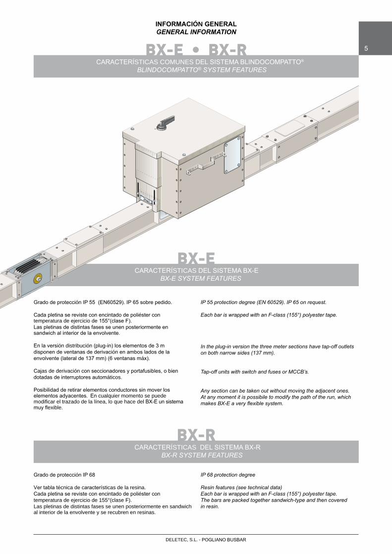
Grado de protección IP 68
Ver tabla técnica de características de la resina.Cada pletina se reviste con encintado de poliéster contemperatura de ejercicio de 155°(clase F).Las pletinas de distintas fases se unen posteriormente en sandwich al interior de la envolvente y se recubren en resinas.
IP 68 protection degree
Resin features (see technical data)Each bar is wrapped with an F-class (155°) polyester tape.The bars are packed together sandwich-type and then covered in resin.
Grado de protección IP 55 (EN60529). IP 65 sobre pedido.
Cada pletina se reviste con encintado de poliéster con temperatura de ejercicio de 155°(clase F).Las pletinas de distintas fases se unen posteriormente en sandwich al interior de la envolvente.
En la versión distribución (plug-in) los elementos de 3 m disponen de ventanas de derivación en ambos lados de la envolvente (lateral de 137 mm) (6 ventanas máx).
Cajas de derivación con seccionadores y portafusibles, o bien dotadas de interruptores automáticos.
Posibilidad de retirar elementos conductores sin mover los elementos adyacentes. En cualquier momento se puede modificar el trazado de la línea, lo que hace del BX-E un sistema muy flexible.
INFORMACIÓN GENERALGENERAL INFORMATION
BX-E • BX-RCARACTERÍSTICAS COMUNES DEL SISTEMA BLINDOCOMPATTO®
BLINDOCOMPATTO® SYSTEM FEATURES
IP 55 protection degree (EN 60529). IP 65 on request.
Each bar is wrapped with an F-class (155°) polyester tape.
In the plug-in version the three meter sections have tap-off outlets on both narrow sides (137 mm).
Tap-off units with switch and fuses or MCCB’s.
Any section can be taken out without moving the adjacent ones. At any moment it is possibile to modify the path of the run, which makes BX-E a very flexible system.
BX-E • BX-R6
INFORMACIÓN GENERALGENERAL INFORMATION
VERSIONES DISPONIBLESAVAILABLE VERSIONS
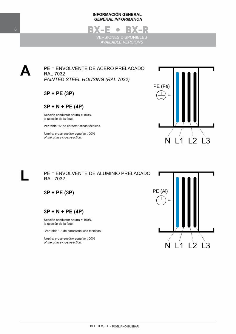
PE = ENVOLVENTE DE ACERO PRELACADO RAL 7032PAINTED STEEL HOUSING (RAL 7032)
3P + PE (3P)
3P + N + PE (4P)Sección conductor neutro = 100% la sección de la fase.
Ver tabla "A" de características técnicas.
Neutral cross-section equal to 100% of the phase cross-section.
A
N L1 L2 L3
PE = ENVOLVENTE DE ALUMINIO PRELACADO RAL 7032
3P + PE (3P)
3P + N + PE (4P)Sección conductor neutro = 100% la sección de la fase.
Ver tabla "L" de características técnicas.
Neutral cross-section equal to 100% of the phase cross-section.
L
N L1 L2 L3
POGLIANO BUSBARDELETEC, S.L. -
PE (Fe)
PE (Al)
DELETEC, S.L. - POGLIANO BUSBAR
BX-E • BX-R 7
INFORMACIÓN GENERALGENERAL INFORMATION
VERSIONES DISPONIBLESAVAILABLE VERSIONS
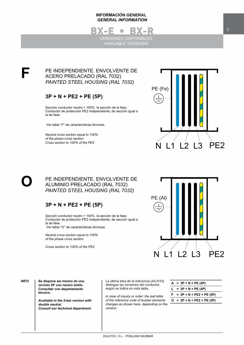
La última letra de la referencia (A/L/F/O) distingue las versiones del conductor, según se indica en esta tabla.
In case of inquiry or order: the last letterof the reference code of busbar elements changes as shown here, depending on the version.
PE INDEPENDIENTE. ENVOLVENTE DE ACERO PRELACADO (RAL 7032)PAINTED STEEL HOUSING (RAL 7032)
3P + N + PE2 + PE (5P)
Sección conductor neutro = 100% la sección de la fase. Conductor de protección PE2 independiente, de sección igual a la de fase.
Ver tabla "F" de características técnicas.
Neutral cross section equal to 100%of the phase cross sectionCross section to 100% of the PE2
F
N L1 L2 L3 PE2
PE INDEPENDIENTE. ENVOLVENTE DE ALUMINIO PRELACADO (RAL 7032)PAINTED STEEL HOUSING (RAL 7032)
3P + N + PE2 + PE (5P)
Sección conductor neutro = 100% la sección de la fase. Conductor de protección PE2 independiente, de sección igual a la de fase. Ver tabla "O" de características técnicas.
Neutral cross section equal to 100%of the phase cross section
Cross section to 100% of the PE2
O
N L1 L2 L3 PE2
Se dispone así mismo de una versión 5P con neutro doble.Consultar con departamento técnico.
Available in the 5-bar version with double neutral.Consult our technical department.
INFO A = 3P + N + PE (4P)
L = 3P + N + PE (4P)
F = 3P + N + PE2 + PE (5P)
O = 3P + N + PE2 + PE (5P)
PE (Fe)
PE (Al)
BX-E • BX-R �• BX-F8
INFORMACIÓN GENERALGENERAL INFORMATION
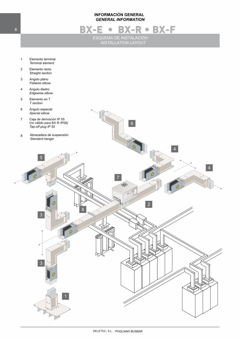
ESQUEMA DE INSTALACIÓNINSTALLATION LAYOUT
1
Elemento terminalTerminal element
2
Elemento rectoStraight section
3
Ángulo planoFlatwise elbow
4
Ángulo diedroEdgewise elbow
5
Elemento en TT section
6
Ángulo especialSpecial elbow
7
Caja de derivación IP 55(no válido para BX-R IP68)Tap-off plug IP 55
8
Abrazadera de suspensión
Standard hanger
5
3
3
1
7
8
6
4
4
2
POGLIANO BUSBARDELETEC, S.L. -
DELETEC, S.L. - POGLIANO BUSBAR
BX-E • BX-F • BX-R 9
INFORMACIÓN GENERALGENERAL INFORMATION
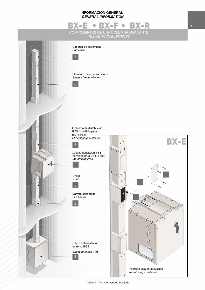
COMPONENTES DE UNA COLUMNA MONTANTERISING MAIN ELEMENTS
Cobertor de extremidad End cover
7
6
5
4
3
2
1
Elemento recto de transporteStraight feeder element
Elemento de distribución IP55 (no válido para BX-R IP68)Straight plug-in element
Caja de derivación IP55(no válido para BX-R IP68)Tap-off plug IP55
UniónJoint
Barrera cortafuegoFire barrier
Caja de alimentación extremo IP55
End feed-in box IP55
BX-E
A
B
C
Inserción caja de derivaciónTap-off plug instaliation

BX-E •BX-F10
INFORMACIÓN GENERALGENERAL DATA
MONTAJE DE LA UNIÓNJOINT INSTALLATION
Retirar las tapas exteriores de la unión con llave del 13. Antes de proceder a montar la unión, verificar la limpieza e integridad de sus componentes.Aproximar los elementos cuidando de que las pletinas conductoras se alojen en sus huecos.
Before installation make sure the joint isclean and that it hasn’t been damagedduring transportation.Draw the element nearer, paying attentionto the insertion of the bars into the joint stack.
1
Juntar los dos elementos todo lo que permiten las placas de unión. Los dos elementos quedarán con unaseparación entre envolventes (ver figura) de 220 mm. Verificar la correcta posición y orden de todos los conductores (Fases, Neutro y PE).Los agujeros asimétricos de la tapa de 137 mm. aseguran la posición correcta de las fases.
Draw the two elements nearer until you reachthe 220 mm position. Check that all conductors are in the right position and aligned.
2
Apretar los tornillos de unión hasta la rotura de sus cabezas (así se garantiza el par de apriete de 60 Nm)
Torque until the double head bolt breaks off (at 60 Nm)
3
220 mm
(1)
(2)
POGLIANO BUSBARDELETEC, S.L. -
DELETEC, S.L. - POGLIANO BUSBAR
BX-E •BX-F 11
INFORMACIÓN GENERAL GENERAL DATA
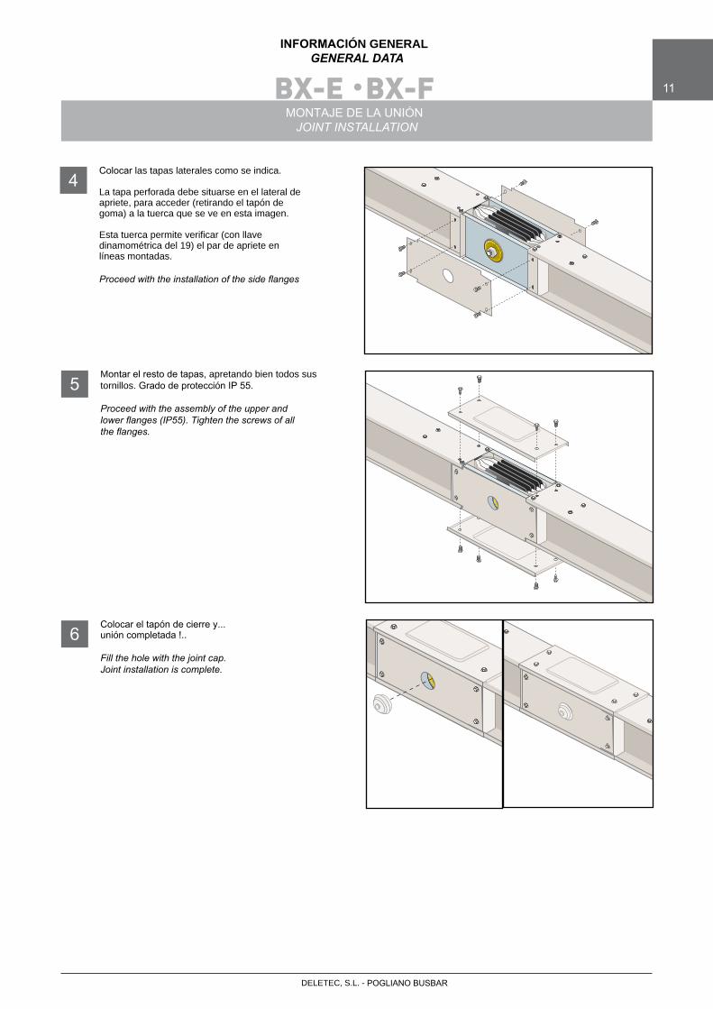
MONTAJE DE LA UNIÓNJOINT INSTALLATION
Colocar las tapas laterales como se indica.
La tapa perforada debe situarse en el lateral de apriete, para acceder (retirando el tapón de goma) a la tuerca que se ve en esta imagen.
Esta tuerca permite verificar (con llave dinamométrica del 19) el par de apriete en líneas montadas.
Proceed with the installation of the side flanges
4
Montar el resto de tapas, apretando bien todos sus tornillos. Grado de protección IP 55.
Proceed with the assembly of the upper andlower flanges (IP55). Tighten the screws of allthe flanges.
5
Colocar el tapón de cierre y...unión completada !..
Fill the hole with the joint cap.Joint installation is complete.
6
BX-R12
INFORMACIÓN GENERALGENERAL DATA
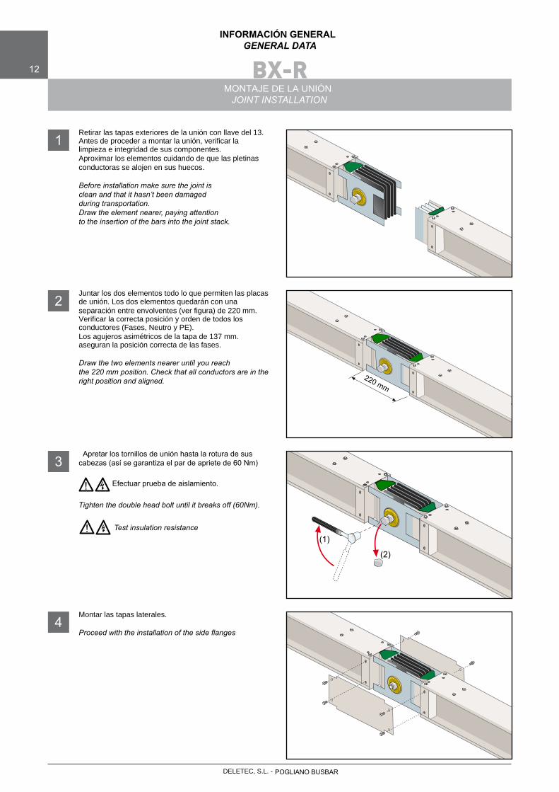
MONTAJE DE LA UNIÓNJOINT INSTALLATION
Retirar las tapas exteriores de la unión con llave del 13. Antes de proceder a montar la unión, verificar la limpieza e integridad de sus componentes.Aproximar los elementos cuidando de que las pletinas conductoras se alojen en sus huecos.
Before installation make sure the joint isclean and that it hasn’t been damagedduring transportation.Draw the element nearer, paying attentionto the insertion of the bars into the joint stack.
1
Juntar los dos elementos todo lo que permiten las placas de unión. Los dos elementos quedarán con unaseparación entre envolventes (ver figura) de 220 mm. Verificar la correcta posición y orden de todos los conductores (Fases, Neutro y PE).Los agujeros asimétricos de la tapa de 137 mm. aseguran la posición correcta de las fases.
Draw the two elements nearer until you reachthe 220 mm position. Check that all conductors are in the right position and aligned.
2
Apretar los tornillos de unión hasta la rotura de sus cabezas (así se garantiza el par de apriete de 60 Nm)
Efectuar prueba de aislamiento.
Tighten the double head bolt until it breaks off (60Nm).
Test insulation resistance
3
Montar las tapas laterales.
Proceed with the installation of the side flanges4
220 mm
!
!(1)
(2)
POGLIANO BUSBARDELETEC, S.L. -
DELETEC, S.L. - POGLIANO BUSBAR
BX-R 13
INFORMAZIONI GENERALIGENERAL DATA
INSTALLAZIONE GIUNTOJOINT INSTALLATION
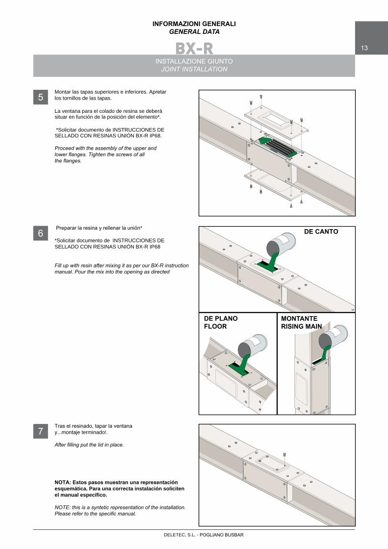
Montar las tapas superiores e inferiores. Apretarlos tornillos de las tapas.
La ventana para el colado de resina se deberá situar en función de la posición del elemento*.
*Solicitar documento de INSTRUCCIONES DE SELLADO CON RESINAS UNIÓN BX-R IP68.
Proceed with the assembly of the upper and lower flanges. Tighten the screws of allthe flanges.
5
Preparar la resina y rellenar la unión*
*Solicitar documento de INSTRUCCIONES DE SELLADO CON RESINAS UNIÓN BX-R IP68
Fill up with resin after mixing it as per our BX-R instruction manual. Pour the mix into the opening as directed
6
Tras el resinado, tapar la ventana y...montaje terminado!.
After filling put the lid in place.
NOTA: Estos pasos muestran una representación esquemática. Para una correcta instalación soliciten el manual específico.
NOTE: this is a syntetic representation of the installation. Please refer to the specific manual.
7
DE CANTO
DE PLANOFLOOR
MONTANTERISING MAIN
BX-E • BX-R
BX-E • BX-R • BX-F14
INFORMACIÓN GENERALGENERAL DATA
COMO MEDIR UN ELEMENTO DE CIERREHOW TO MEASURE A GAP BETWEEN TWO SECTIONS
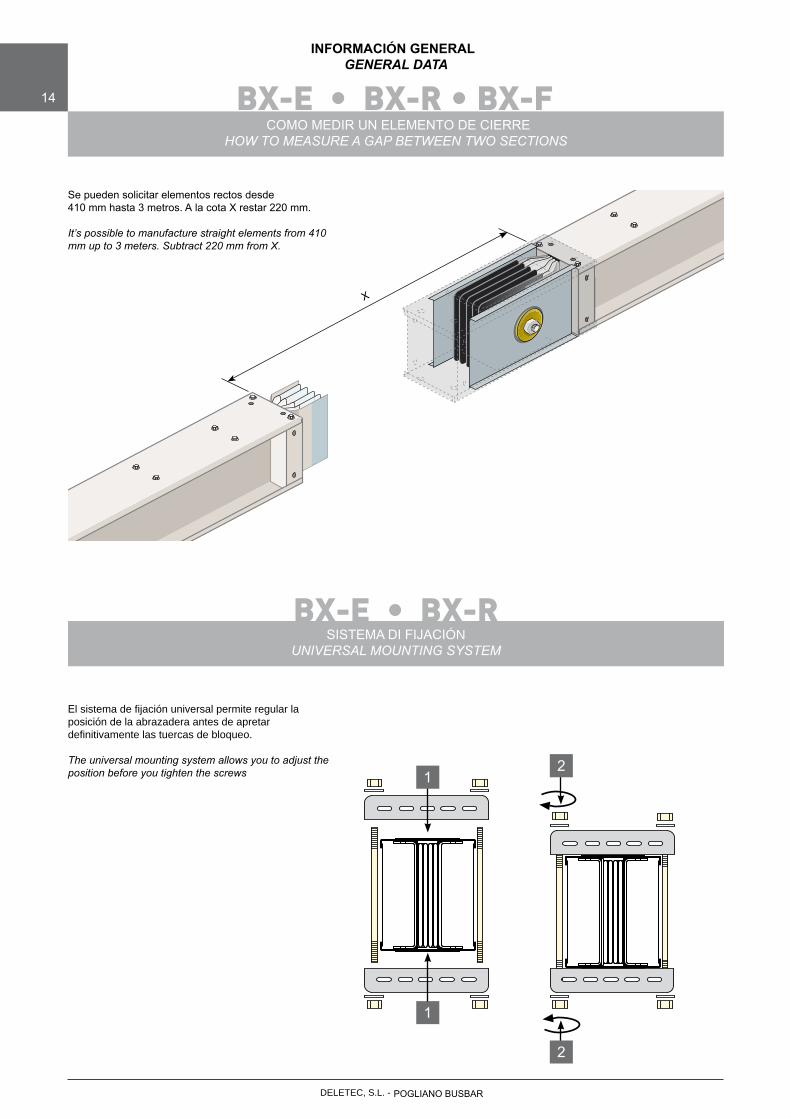
Se pueden solicitar elementos rectos desde410 mm hasta 3 metros. A la cota X restar 220 mm.
It’s possible to manufacture straight elements from 410 mm up to 3 meters. Subtract 220 mm from X.
X
SISTEMA DI FIJACIÓNUNIVERSAL MOUNTING SYSTEM
El sistema de fijación universal permite regular la posición de la abrazadera antes de apretar definitivamente las tuercas de bloqueo.
The universal mounting system allows you to adjust the position before you tighten the screws
1
12
2
POGLIANO BUSBARDELETEC, S.L. -
DELETEC, S.L. - POGLIANO BUSBAR
BX-E • BX-R • BX-F 15
INFORMAZIONI GENERALIGENERAL DATA
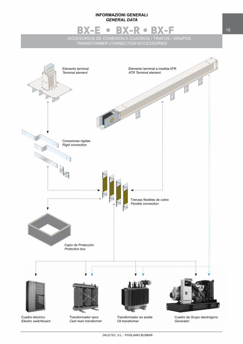
ACCESORIOS DE CONEXIÓN A CUADROS / TRAFOS / GRUPOSTRANSFORMER CONNECTION ACCESSORIES
Elemento terminalTerminal element
Conexiones rígidasRigid connection
Trenzas flexibles de cobreFlexible connection
Cajón de ProtecciónProtection box
Cuadro eléctricoElectric switchboard
Transformador secoCast resin transformer
Transformador en aceiteOil transformer
Cuadro de Grupo electrógenoGenerator
Elemento terminal a medida ATRATR Terminal element
BX-E • BX-RBX-EBX-R
16
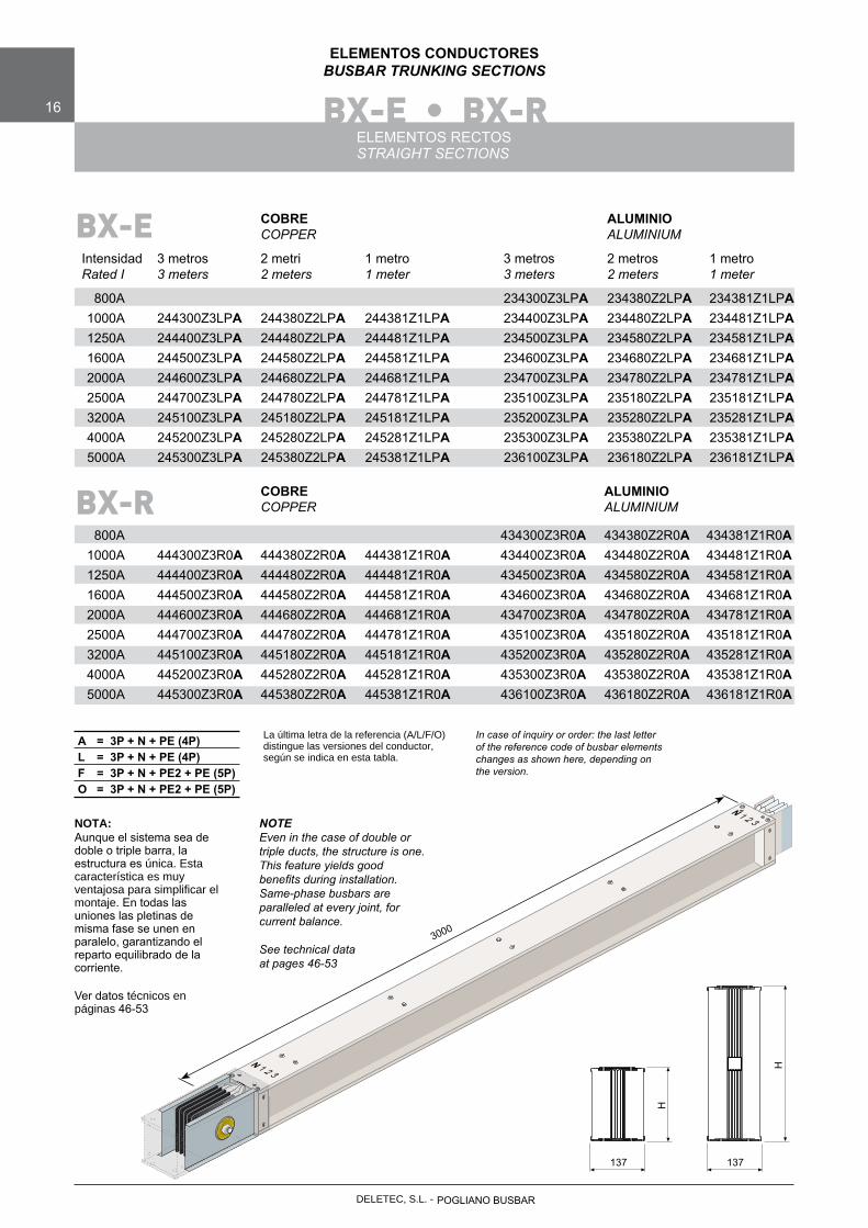
ELEMENTOS CONDUCTORESBUSBAR TRUNKING SECTIONS
ELEMENTOS RECTOSSTRAIGHT SECTIONS
COBRE ALUMINIO COPPER ALUMINIUM
Intensidad 3 metros 2 metri 1 metro 3 metros 2 metros 1 metro Rated I 3 meters 2 meters 1 meter 3 meters 2 meters 1 meter
800A 234300Z3LPA 234380Z2LPA 234381Z1LPA 1000A 244300Z3LPA 244380Z2LPA 244381Z1LPA 234400Z3LPA 234480Z2LPA 234481Z1LPA 1250A 244400Z3LPA 244480Z2LPA 244481Z1LPA 234500Z3LPA 234580Z2LPA 234581Z1LPA 1600A 244500Z3LPA 244580Z2LPA 244581Z1LPA 234600Z3LPA 234680Z2LPA 234681Z1LPA 2000A 244600Z3LPA 244680Z2LPA 244681Z1LPA 234700Z3LPA 234780Z2LPA 234781Z1LPA 2500A 244700Z3LPA 244780Z2LPA 244781Z1LPA 235100Z3LPA 235180Z2LPA 235181Z1LPA 3200A 245100Z3LPA 245180Z2LPA 245181Z1LPA 235200Z3LPA 235280Z2LPA 235281Z1LPA 4000A 245200Z3LPA 245280Z2LPA 245281Z1LPA 235300Z3LPA 235380Z2LPA 235381Z1LPA 5000A 245300Z3LPA 245380Z2LPA 245381Z1LPA 236100Z3LPA 236180Z2LPA 236181Z1LPA
NOTA:Aunque el sistema sea de doble o triple barra, la estructura es única. Esta característica es muy ventajosa para simplificar el montaje. En todas las uniones las pletinas de misma fase se unen en paralelo, garantizando el reparto equilibrado de la corriente.
Ver datos técnicos en páginas 46-53
NOTEEven in the case of double or triple ducts, the structure is one. This feature yields good benefits during installation. Same-phase busbars are paralleled at every joint, for current balance.
See technical data at pages 46-53
3000
N 1 2 3
N 1 2 3
137 137
H
H
La última letra de la referencia (A/L/F/O) distingue las versiones del conductor, según se indica en esta tabla.
A = 3P + N + PE (4P)L = 3P + N + PE (4P)F = 3P + N + PE2 + PE (5P)O = 3P + N + PE2 + PE (5P)
BX-E
COBRE ALUMINIO COPPER ALUMINIUM
800A 434300Z3R0A 434380Z2R0A 434381Z1R0A 1000A 444300Z3R0A 444380Z2R0A 444381Z1R0A 434400Z3R0A 434480Z2R0A 434481Z1R0A 1250A 444400Z3R0A 444480Z2R0A 444481Z1R0A 434500Z3R0A 434580Z2R0A 434581Z1R0A 1600A 444500Z3R0A 444580Z2R0A 444581Z1R0A 434600Z3R0A 434680Z2R0A 434681Z1R0A 2000A 444600Z3R0A 444680Z2R0A 444681Z1R0A 434700Z3R0A 434780Z2R0A 434781Z1R0A 2500A 444700Z3R0A 444780Z2R0A 444781Z1R0A 435100Z3R0A 435180Z2R0A 435181Z1R0A 3200A 445100Z3R0A 445180Z2R0A 445181Z1R0A 435200Z3R0A 435280Z2R0A 435281Z1R0A 4000A 445200Z3R0A 445280Z2R0A 445281Z1R0A 435300Z3R0A 435380Z2R0A 435381Z1R0A 5000A 445300Z3R0A 445380Z2R0A 445381Z1R0A 436100Z3R0A 436180Z2R0A 436181Z1R0A
BX-R
In case of inquiry or order: the last letter of the reference code of busbar elements changes as shown here, depending on the version.
POGLIANO BUSBARDELETEC, S.L. -
DELETEC, S.L. - POGLIANO BUSBAR
BX-E
BX-R
BX-E • BX-R 17
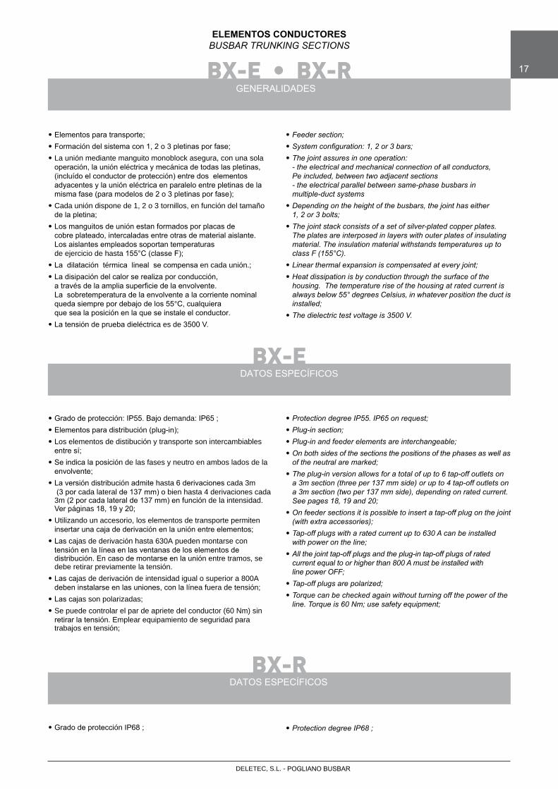
ELEMENTOS CONDUCTORESBUSBAR TRUNKING SECTIONS
GENERALIDADES
• Elementos para transporte;• Formación del sistema con 1, 2 o 3 pletinas por fase;• La unión mediante manguito monoblock asegura, con una sola
operación, la unión eléctrica y mecánica de todas las pletinas,(incluído el conductor de protección) entre dos elementos adyacentes y la unión eléctrica en paralelo entre pletinas de la misma fase (para modelos de 2 o 3 pletinas por fase);
• Cada unión dispone de 1, 2 o 3 tornillos, en función del tamañode la pletina;
• Los manguitos de unión estan formados por placas decobre plateado, intercaladas entre otras de material aislante.Los aislantes empleados soportan temperaturasde ejercicio de hasta 155°C (classe F);
• La dilatación térmica lineal se compensa en cada unión.;• La disipación del calor se realiza por conducción,
a través de la amplia superficie de la envolvente.La sobretemperatura de la envolvente a la corriente nominalqueda siempre por debajo de los 55°C, cualquieraque sea la posición en la que se instale el conductor.
• La tensión de prueba dieléctrica es de 3500 V.
• Feeder section;• System configuration: 1, 2 or 3 bars;• The joint assures in one operation: - the electrical and mechanical connection of all conductors, Pe included, between two adjacent sections - the electrical parallel between same-phase busbars in multiple-duct systems• Depending on the height of the busbars, the joint has either 1, 2 or 3 bolts;• The joint stack consists of a set of silver-plated copper plates. The plates are interposed in layers with outer plates of insulating material. The insulation material withstands temperatures up to class F (155°C).• Linear thermal expansion is compensated at every joint;• Heat dissipation is by conduction through the surface of the housing. The temperature rise of the housing at rated current is always below 55° degrees Celsius, in whatever position the duct is installed;• The dielectric test voltage is 3500 V.
DATOS ESPECÍFICOS
DATOS ESPECÍFICOS
• Grado de protección: IP55. Bajo demanda: IP65 ;• Elementos para distribución (plug-in);• Los elementos de distibución y transporte son intercambiables
entre sí;• Se indica la posición de las fases y neutro en ambos lados de la
envolvente;• La versión distribución admite hasta 6 derivaciones cada 3m
(3 por cada lateral de 137 mm) o bien hasta 4 derivaciones cada 3m (2 por cada lateral de 137 mm) en función de la intensidad.Ver páginas 18, 19 y 20;
• Utilizando un accesorio, los elementos de transporte permiteninsertar una caja de derivación en la unión entre elementos;
• Las cajas de derivación hasta 630A pueden montarse con tensión en la línea en las ventanas de los elementos de distribución. En caso de montarse en la unión entre tramos, se debe retirar previamente la tensión.
• Las cajas de derivación de intensidad igual o superior a 800Adeben instalarse en las uniones, con la línea fuera de tensión;
• Las cajas son polarizadas;• Se puede controlar el par de apriete del conductor (60 Nm) sin
retirar la tensión. Emplear equipamiento de seguridad para trabajos en tensión;
• Protection degree IP55. IP65 on request;• Plug-in section;• Plug-in and feeder elements are interchangeable; • On both sides of the sections the positions of the phases as well as of the neutral are marked;• The plug-in version allows for a total of up to 6 tap-off outlets on a 3m section (three per 137 mm side) or up to 4 tap-off outlets on a 3m section (two per 137 mm side), depending on rated current. See pages 18, 19 and 20;• On feeder sections it is possible to insert a tap-off plug on the joint (with extra accessories);• Tap-off plugs with a rated current up to 630 A can be installed with power on the line;• All the joint tap-off plugs and the plug-in tap-off plugs of rated current equal to or higher than 800 A must be installed with line power OFF;• Tap-off plugs are polarized;• Torque can be checked again without turning off the power of the line. Torque is 60 Nm; use safety equipment;
• Grado de protección IP68 ; • Protection degree IP68 ;
BX-EBX-E BX-R
18
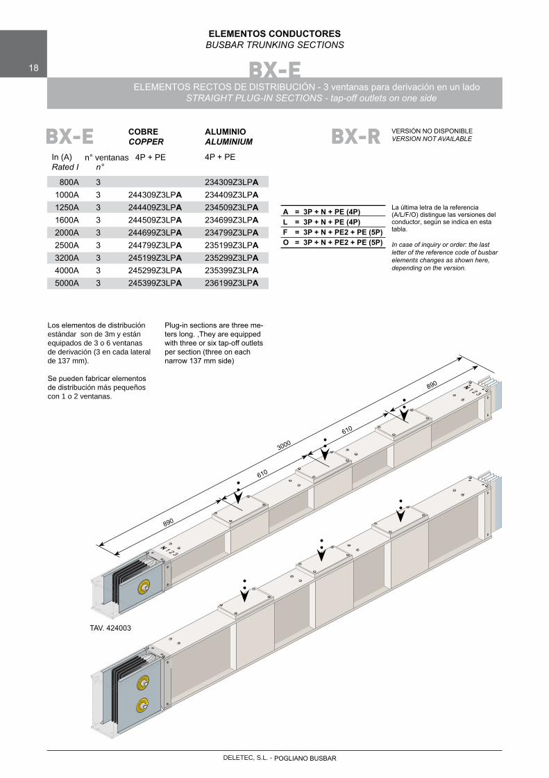
ELEMENTOS CONDUCTORESBUSBAR TRUNKING SECTIONS
ELEMENTOS RECTOS DE DISTRIBUCIÓN - 3 ventanas para derivación en un ladoSTRAIGHT PLUG-IN SECTIONS - tap-off outlets on one side
Los elementos de distribución estándar son de 3m y están equipados de 3 o 6 ventanas de derivación (3 en cada lateral de 137 mm).
Se pueden fabricar elementos de distribución más pequeños con 1 o 2 ventanas.
COBRE ALUMINIO COPPER ALUMINIUM
In (A) n° ventanas 4P + PE 4P+PE Rated I n°
800A 3 234309Z3LPA 1000A 3 244309Z3LPA 234409Z3LPA 1250A 3 244409Z3LPA 234509Z3LPA 1600A 3 244509Z3LPA 234699Z3LPA 2000A 3 244699Z3LPA 234799Z3LPA 2500A 3 244799Z3LPA 235199Z3LPA 3200A 3 245199Z3LPA 235299Z3LPA 4000A 3 245299Z3LPA 235399Z3LPA 5000A 3 245399Z3LPA 236199Z3LPA
La última letra de la referencia (A/L/F/O) distingue las versiones del conductor, según se indica en esta tabla.
In case of inquiry or order: the last letter of the reference code of busbar elements changes as shown here, depending on the version.
A = 3P + N + PE (4P)L = 3P + N + PE (4P)F = 3P + N + PE2 + PE (5P)O = 3P + N + PE2 + PE (5P)
BX-R VERSIÓN NO DISPONIBLEVERSION NOT AVAILABLEBX-E
Plug-in sections are three me-ters long. ,They are equipped with three or six tap-off outlets per section (three on each narrow 137 mm side)
3000
N 1 2 3
N 1 2 3
890
610
610
890
TAV. 424003
POGLIANO BUSBARDELETEC, S.L. -
DELETEC, S.L. - POGLIANO BUSBAR
BX-E 19
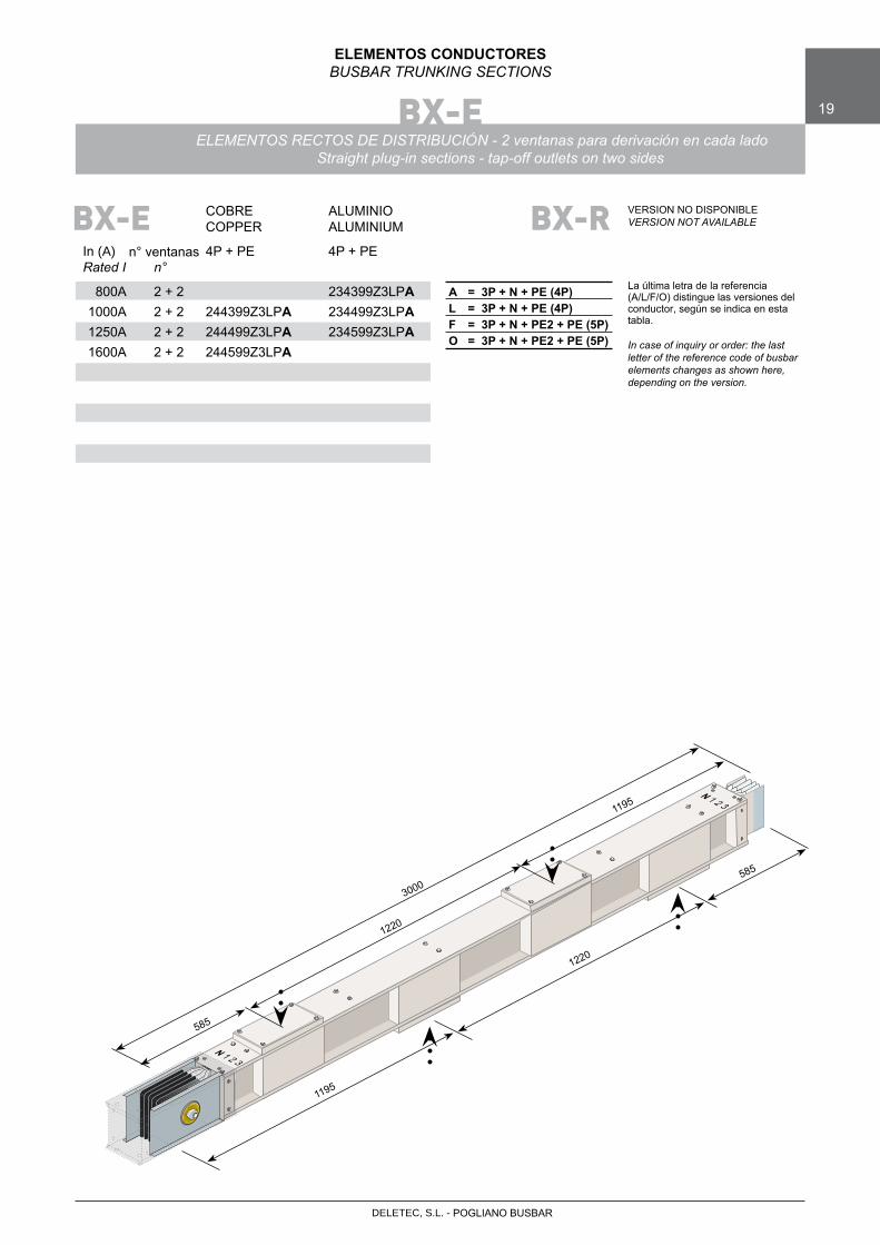
ELEMENTOS CONDUCTORESBUSBAR TRUNKING SECTIONS
ELEMENTOS RECTOS DE DISTRIBUCIÓN - 2 ventanas para derivación en cada ladoStraight plug-in sections - tap-off outlets on two sides
COBRE ALUMINIO COPPER ALUMINIUM
4Pn° ventanasIn (A) +PE 4P+PE Rated I n°
800A 2 + 2 234399Z3LPA 1000A 2 + 2 244399Z3LPA 234499Z3LPA 1250A 2 + 2 244499Z3LPA 234599Z3LPA 1600A 2 + 2 244599Z3LPA
La última letra de la referencia (A/L/F/O) distingue las versiones del conductor, según se indica en esta tabla.
In case of inquiry or order: the last letter of the reference code of busbar elements changes as shown here, depending on the version.
A = 3P + N + PE (4P)L = 3P + N + PE (4P)F = 3P + N + PE2 + PE (5P)O = 3P + N + PE2 + PE (5P)
BX-R VERSION NO DISPONIBLEVERSION NOT AVAILABLEBX-E
3000
N 1 2 3
N 1 2 3
585
1220
1195
1220
585
1195
BX-EBX-E BX-R
20
ELEMENTI CONDUTTORIBUSBAR TRUNKING SECTIONS
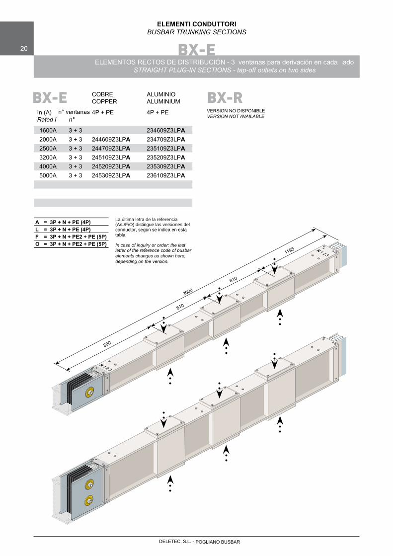
ELEMENTOS RECTOS DE DISTRIBUCIÓN - 3 ventanas para derivación en cada ladoSTRAIGHT PLUG-IN SECTIONS - tap-off outlets on two sides
COBRE ALUMINIO COPPER ALUMINIUM
4Pn° ventanasIn (A) +PE 4P+PE Rated I n°
1600A 3 + 3 234609Z3LPA 2000A 3 + 3 244609Z3LPA 234709Z3LPA 2500A 3 + 3 244709Z3LPA 235109Z3LPA 3200A 3 + 3 245109Z3LPA 235209Z3LPA 4000A 3 + 3 245209Z3LPA 235309Z3LPA 5000A 3 + 3 245309Z3LPA 236109Z3LPA
La última letra de la referencia (A/L/F/O) distingue las versiones del conductor, según se indica en esta tabla.
In case of inquiry or order: the last letter of the reference code of busbarelements changes as shown here, depending on the version.
A = 3P + N + PE (4P)L = 3P + N + PE (4P)F = 3P + N + PE2 + PE (5P)O = 3P + N + PE2 + PE (5P)
BX-RVERSION NO DISPONIBLEVERSION NOT AVAILABLE
BX-E
3000
N 1 2 3
N 1 2 3
890
610
1195
610
POGLIANO BUSBARDELETEC, S.L. -
DELETEC, S.L. - POGLIANO BUSBAR
BX-EBX-E BX-R
21
ELEMENTOS CONDUCTORESBUSBAR TRUNKING SECTIONS
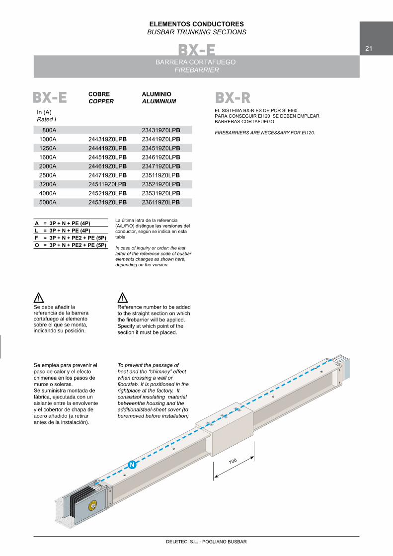
BARRERA CORTAFUEGOFIREBARRIER
Se emplea para prevenir el paso de calor y el efecto chimenea en los pasos de muros o soleras. Se suministra montada defábrica, ejecutada con un aislante entre la envolvente y el cobertor de chapa de acero añadido (a retirar antes de la instalación).
COBRE ALUMINIO COPPER ALUMINIUM
In (A)Rated I
800A 234319Z0LPB 1000A 244319Z0LPB 234419Z0LPB 1250A 244419Z0LPB 234519Z0LPB 1600A 244519Z0LPB 234619Z0LPB 2000A 244619Z0LPB 234719Z0LPB 2500A 244719Z0LPB 235119Z0LPB 3200A 245119Z0LPB 235219Z0LPB 4000A 245219Z0LPB 235319Z0LPB 5000A 245319Z0LPB 236119Z0LPB
La última letra de la referencia (A/L/F/O) distingue las versiones del conductor, según se indica en esta tabla.
In case of inquiry or order: the last letter of the reference code of busbar elements changes as shown here, depending on the version.
A = 3P + N + PE (4P)L = 3P + N + PE (4P)F = 3P + N + PE2 + PE (5P)O = 3P + N + PE2 + PE (5P)
BX-E
To prevent the passage of heat and the “chimney” effect when crossing a wall or floorslab. It is positioned in the rightplace at the factory. It consistsof insulating material between the housing and the additional steel-sheet cover (to be removed before installation)
Se debe añadir la referencia de la barrera cortafuego al elemento sobre el que se monta, indicando su posición.
Reference number to be added to the straight section on which thefirebarrierwillbeapplied.Specify at which point of the section it must be placed.
! !
N
BX-R
EL SISTEMA BX-R ES DE POR SÍ EI60.PARA CONSEGUIR EI120 SE DEBEN EMPLEAR BARRERAS CORTAFUEGO
FIREBARRIERS ARE NECESSARY FOR EI120.
700
BX-E • BX-RBX-E BX-R
22
ELEMENTOS CONDUCTORESBUSBAR TRUNKING SECTIONS
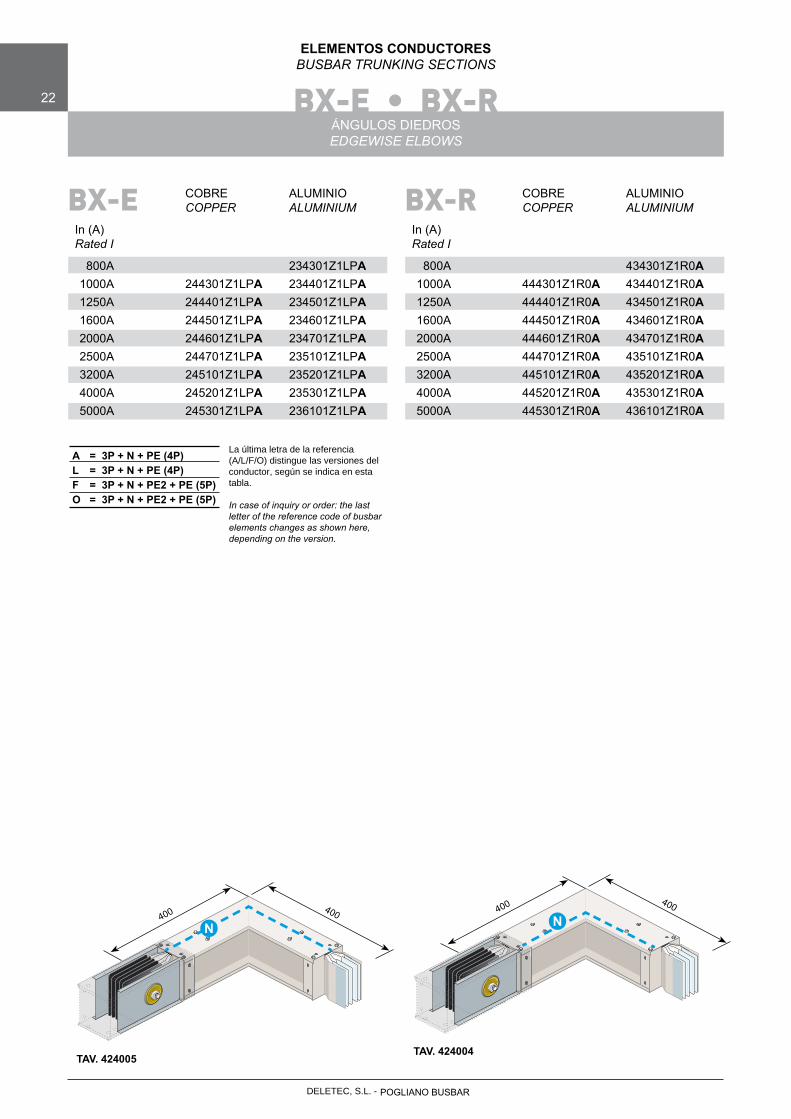
ÁNGULOS DIEDROSEDGEWISE ELBOWS
La última letra de la referencia (A/L/F/O) distingue las versiones del conductor, según se indica en esta tabla.
In case of inquiry or order: the last letter of the reference code of busbar elements changes as shown here, depending on the version.
A = 3P + N + PE (4P)L = 3P + N + PE (4P)F = 3P + N + PE2 + PE (5P)O = 3P + N + PE2 + PE (5P)
COBRE ALUMINIO COPPER ALUMINIUM
In (A)Rated I
800A 234301Z1LPA 1000A 244301Z1LPA 234401Z1LPA 1250A 244401Z1LPA 234501Z1LPA 1600A 244501Z1LPA 234601Z1LPA 2000A 244601Z1LPA 234701Z1LPA 2500A 244701Z1LPA 235101Z1LPA 3200A 245101Z1LPA 235201Z1LPA 4000A 245201Z1LPA 235301Z1LPA 5000A 245301Z1LPA 236101Z1LPA
BX-E
400 400
N
TAV. 424005
400 400
N
TAV. 424004
COBRE ALUMINIO COPPER ALUMINIUM
In (A)Rated I
800A 434301Z1R0A 1000A 444301Z1R0A 434401Z1R0A 1250A 444401Z1R0A 434501Z1R0A 1600A 444501Z1R0A 434601Z1R0A 2000A 444601Z1R0A 434701Z1R0A 2500A 444701Z1R0A 435101Z1R0A 3200A 445101Z1R0A 435201Z1R0A 4000A 445201Z1R0A 435301Z1R0A 5000A 445301Z1R0A 436101Z1R0A
BX-R
POGLIANO BUSBARDELETEC, S.L. -

DELETEC, S.L. - POGLIANO BUSBAR
BX-E • BX-RBX-E BX-R
23
ELEMENTOS CONDUCTORESBUSBAR TRUNKING SECTIONS
ÁNGULOS PLANOSFLATWISE ELBOWS
COBRE ALUMINIO COPPER ALUMINIUM
In (A)Rated I
800A 234302Z1LPA 1000A 244302Z1LPA 234402Z1LPA 1250A 244402Z1LPA 234502Z1LPA 1600A 244502Z1LPA 234602Z1LPA 2000A 244602Z1LPA 234702Z1LPA 2500A 244702Z1LPA 235102Z2LPA 3200A 245102Z2LPA 235202Z2LPA 4000A 245202Z2LPA 235302Z2LPA 5000A 245302Z3LPA 236102Z2LPA
BX-E
La última letra de la referencia (A/L/F/O) distingue las versiones del conductor, según se indica en esta tabla.
In case of inquiry or order: the last letter of the reference code of busbar elements changes as shown here, depending on the version.
A = 3P + N + PE (4P)L = 3P + N + PE (4P)F = 3P + N + PE2 + PE (5P)O = 3P + N + PE2 + PE (5P)
B
A
N
Cu Al In (A) A=B A=B Rated I
800A 400 1000A 400 400 1250A 400 400 1600A 400 400 2000A 500 500 2500A 500 650 3200A 650 650 4000A 650 650 5000A 650 850
Cotas
TAV. 424006
COBRE ALUMINIO COPPER ALUMINIUM
In (A)Rated I
800A 434302Z1R0A 1000A 444302Z1R0A 434402Z1R0A 1250A 444402Z1R0A 434502Z1R0A 1600A 444502Z1R0A 434602Z1R0A 2000A 444602Z1R0A 434702Z1R0A 2500A 444702Z1R0A 435102Z2R0A 3200A 445102Z2R0A 435202Z2R0A 4000A 445202Z2R0A 435302Z2R0A 5000A 445302Z3R0A 436102Z2R0A
BX-R

BX-E • BX-RBX-E BX-R
24
ELEMENTOS CONDUCTORESBUSBAR TRUNKING SECTIONS
ÁNGULO EN T DIEDROEDGEWISE T
COBRE ALUMINIO COPPER ALUMINIUM
In (A)Rated I
800A 234307Z2LPA 1000A 244307Z2LPA 234407Z2LPA 1250A 244407Z2LPA 234507Z2LPA 1600A 244507Z2LPA 234607Z2LPA 2000A 244607Z2LPA 234707Z2LPA 2500A 244707Z2LPA 235107Z2LPA 3200A 245107Z2LPA 235207Z2LPA 4000A 245207Z2LPA 235307Z2LPA 5000A 245307Z2LPA 236107Z2LPA
BX-E
La última letra de la referencia (A/L/F/O) distingue las versiones del conductor, según se indica en esta tabla.
In case of inquiry or order: the last letter of the reference code of busbar elements changes as shown here, depending on the version.
A = 3P + N + PE (4P)L = 3P + N + PE (4P)F = 3P + N + PE2 + PE (5P)O = 3P + N + PE2 + PE (5P)
Cu Al In (A) A1 A2 B A1 A2 B Rated I
800A 600 600 600 1000A 600 600 600 600 600 600 1250A 600 600 600 600 600 600 1600A 600 600 600 600 600 600 2000A 600 600 600 600 600 600 2500A 600 600 600 600 600 600 3200A 600 600 600 600 600 600 4000A 600 600 600 600 600 600 5000A 600 600 600 600 600 700
Cotas
Nota: Consultar con nuestro departamento técnico para posición del neutro diferente a la mostrada en la figura.
Note: if you wish the neutral to be in a different position please contact our technical department
! !
COBRE ALUMINIO COPPER ALUMINIUM
In (A)Rated I
800A 434307Z2R0A 1000A 444307Z2R0A 434407Z2R0A 1250A 444407Z2R0A 434507Z2R0A 1600A 444507Z2R0A 434607Z2R0A 2000A 444607Z2R0A 434707Z2R0A 2500A 444707Z2R0A 435107Z2R0A 3200A 445107Z2R0A 435207Z2R0A 4000A 445207Z2R0A 435307Z2R0A 5000A 445307Z2R0A 436107Z2R0A
BX-R
TAV. 424035
N N
A1
A2
B
POGLIANO BUSBARDELETEC, S.L. -
DELETEC, S.L. - POGLIANO BUSBAR
BX-E • BX-RBX-E BX-R
25
ELEMENTOS CONDUCTORESBUSBAR TRUNKING SECTIONS
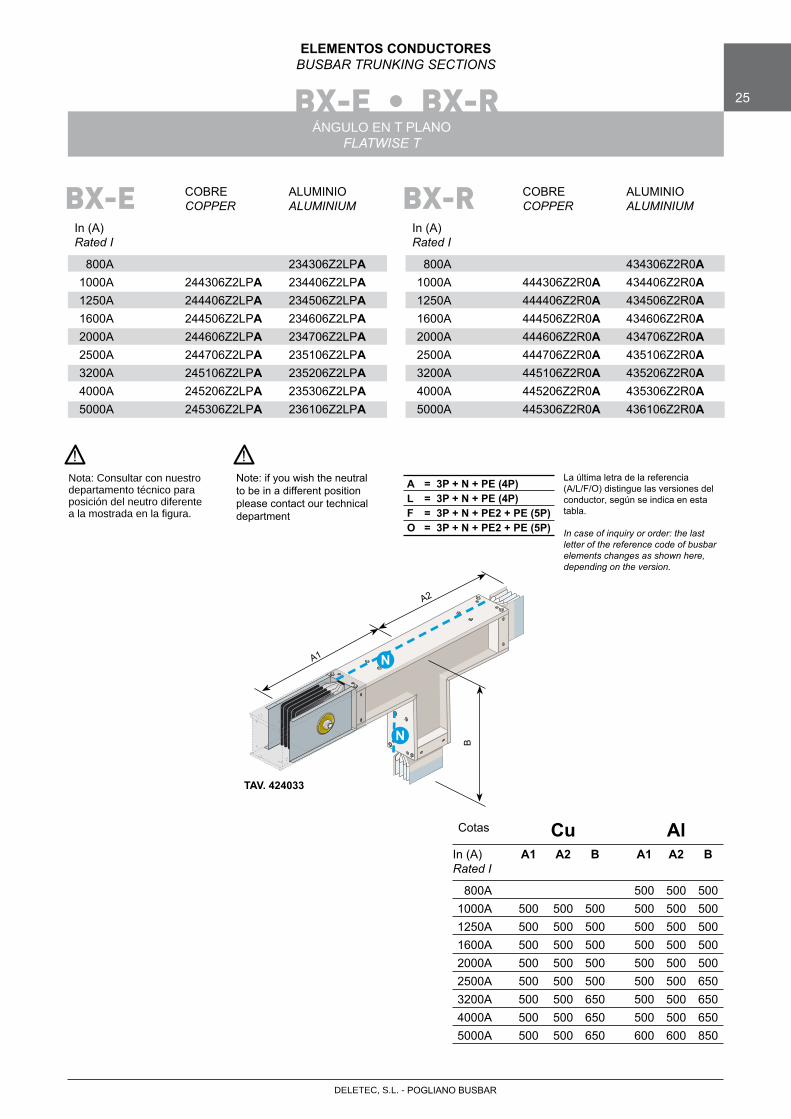
ÁNGULO EN T PLANOFLATWISE T
COBRE ALUMINIO COPPER ALUMINIUM
In (A)Rated I
800A 234306Z2LPA 1000A 244306Z2LPA 234406Z2LPA 1250A 244406Z2LPA 234506Z2LPA 1600A 244506Z2LPA 234606Z2LPA 2000A 244606Z2LPA 234706Z2LPA 2500A 244706Z2LPA 235106Z2LPA 3200A 245106Z2LPA 235206Z2LPA 4000A 245206Z2LPA 235306Z2LPA 5000A 245306Z2LPA 236106Z2LPA
BX-E
La última letra de la referencia (A/L/F/O) distingue las versiones del conductor, según se indica en esta tabla.
In case of inquiry or order: the last letter of the reference code of busbar elements changes as shown here, depending on the version.
A = 3P + N + PE (4P)L = 3P + N + PE (4P)F = 3P + N + PE2 + PE (5P)O = 3P + N + PE2 + PE (5P)
Cu Al In (A) A1 A2 B A1 A2 B Rated I
800A 500 500 500 1000A 500 500 500 500 500 500 1250A 500 500 500 500 500 500 1600A 500 500 500 500 500 500 2000A 500 500 500 500 500 500 2500A 500 500 500 500 500 650 3200A 500 500 650 500 500 650 4000A 500 500 650 500 500 650 5000A 500 500 650 600 600 850
Cotas
A1
N
TAV. 424033
A2
B
N
Nota: Consultar con nuestro departamento técnico para posición del neutro diferente a la mostrada en la figura.
Note: if you wish the neutral to be in a different position please contact our technical department
! !
COBRE ALUMINIO COPPER ALUMINIUM
In (A)Rated I
800A 434306Z2R0A 1000A 444306Z2R0A 434406Z2R0A 1250A 444406Z2R0A 434506Z2R0A 1600A 444506Z2R0A 434606Z2R0A 2000A 444606Z2R0A 434706Z2R0A 2500A 444706Z2R0A 435106Z2R0A 3200A 445106Z2R0A 435206Z2R0A 4000A 445206Z2R0A 435306Z2R0A 5000A 445306Z2R0A 436106Z2R0A
BX-R
BX-E • BX-R26
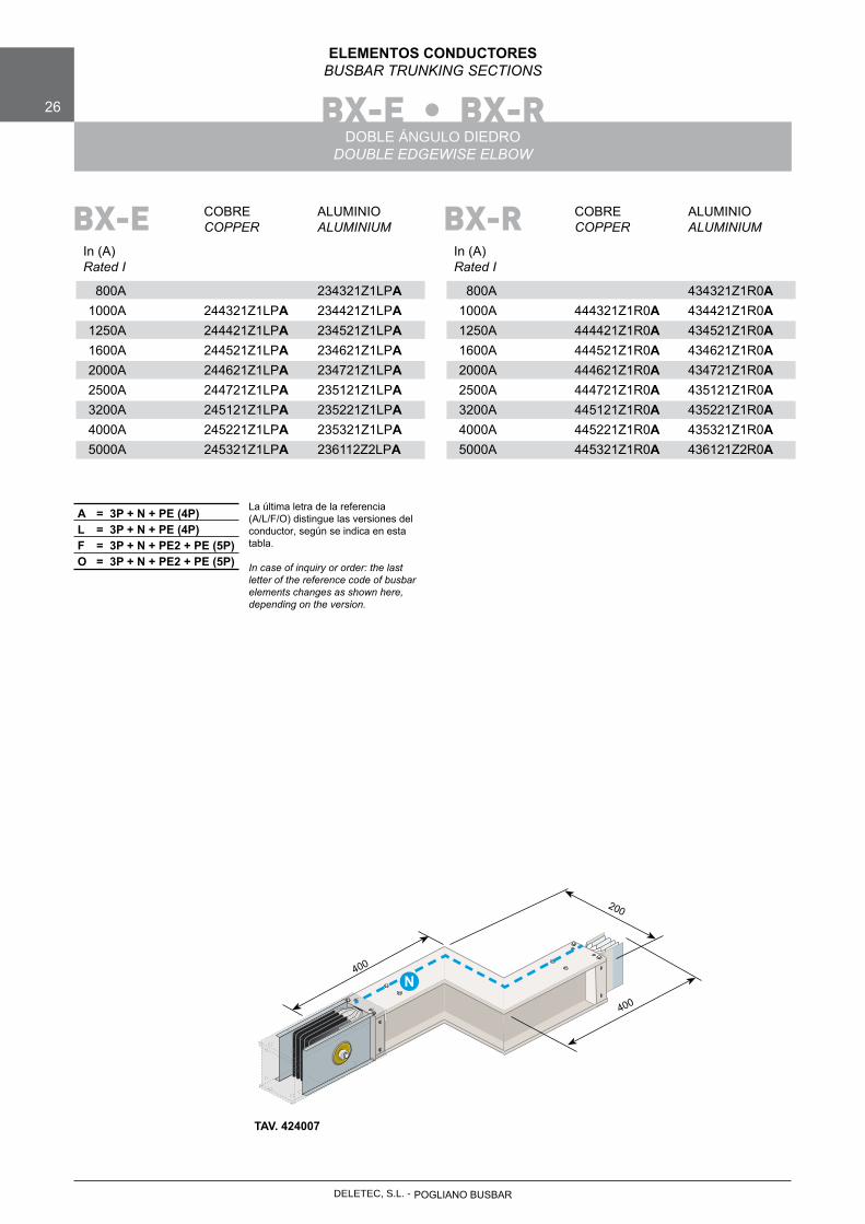
ELEMENTOS CONDUCTORESBUSBAR TRUNKING SECTIONS
DOBLE ÁNGULO DIEDRODOUBLE EDGEWISE ELBOW
COBRE ALUMINIO COPPER ALUMINIUM
In (A)Rated I
800A 234321Z1LPA 1000A 244321Z1LPA 234421Z1LPA 1250A 244421Z1LPA 234521Z1LPA 1600A 244521Z1LPA 234621Z1LPA 2000A 244621Z1LPA 234721Z1LPA 2500A 244721Z1LPA 235121Z1LPA 3200A 245121Z1LPA 235221Z1LPA 4000A 245221Z1LPA 235321Z1LPA 5000A 245321Z1LPA 236112Z2LPA
BX-E
La última letra de la referencia (A/L/F/O) distingue las versiones del conductor, según se indica en esta tabla.
In case of inquiry or order: the last letter of the reference code of busbar elements changes as shown here, depending on the version.
A = 3P + N + PE (4P)L = 3P + N + PE (4P)F = 3P + N + PE2 + PE (5P)O = 3P + N + PE2 + PE (5P)
400
N
TAV. 424007
400
200
COBRE ALUMINIO COPPER ALUMINIUM
In (A)Rated I
800A 434321Z1R0A 1000A 444321Z1R0A 434421Z1R0A 1250A 444421Z1R0A 434521Z1R0A 1600A 444521Z1R0A 434621Z1R0A 2000A 444621Z1R0A 434721Z1R0A 2500A 444721Z1R0A 435121Z1R0A 3200A 445121Z1R0A 435221Z1R0A 4000A 445221Z1R0A 435321Z1R0A 5000A 445321Z1R0A 436121Z2R0A
BX-R
POGLIANO BUSBARDELETEC, S.L. -

DELETEC, S.L. - POGLIANO BUSBAR
BX-E • BX-R 27
ELEMENTOS CONDUCTORESBUSBAR TRUNKING SECTIONS
DOBLE ÁNGULO PLANODOUBLE FLATWISE ELBOW
COBRE ALUMINIO COPPER ALUMINIUM
In (A)Rated I
800A 234322Z1LPA 1000A 244322Z1LPA 234422Z1LPA 1250A 244422Z1LPA 234522Z2LPA 1600A 244522Z2LPA 234622Z2LPA 2000A 244622Z2LPA 234722Z2LPA 2500A 244722Z2LPA 235122Z2LPA 3200A 245122Z2LPA 235222Z2LPA 4000A 245222Z2LPA 235322Z2LPA 5000A 245322Z2LPA 236122Z2LPA
BX-E
La última letra de la referencia (A/L/F/O) distingue las versiones del conductor, según se indica en esta tabla.
In case of inquiry or order: the last letter of the reference code of busbar elements changes as shown here, depending on the version.
A = 3P + N + PE (4P)L = 3P + N + PE (4P)F = 3P + N + PE2 + PE (5P)O = 3P + N + PE2 + PE (5P)
B
TAV. 424008
A
C
N N
Cu Al In (A) A B C A B C Rated I
800A 400 400 185 1000A 400 400 185 400 400 195 1250A 400 400 185 400 400 225 1600A 400 400 225 400 400 270 2000A 400 400 255 500 500 320 2500A 500 500 290 650 650 390 3200A 650 650 350 650 650 480 4000A 650 650 410 650 650 515 5000A 650 650 480 850 850 690
Cotas
TAV. 424009
COBRE ALUMINIO COPPER ALUMINIUM
In (A)Rated I
800A 434322Z1R0A 1000A 444322Z1R0A 434422Z1R0A 1250A 444422Z1R0A 434522Z2R0A 1600A 444522Z2R0A 434622Z2R0A 2000A 444622Z2R0A 434722Z2R0A 2500A 444722Z2R0A 435122Z2R0A 3200A 445122Z2R0A 435222Z2R0A 4000A 445222Z2R0A 435322Z2R0A 5000A 445322Z2R0A 436122Z2R0A
BX-R
BX-E • BX-R28
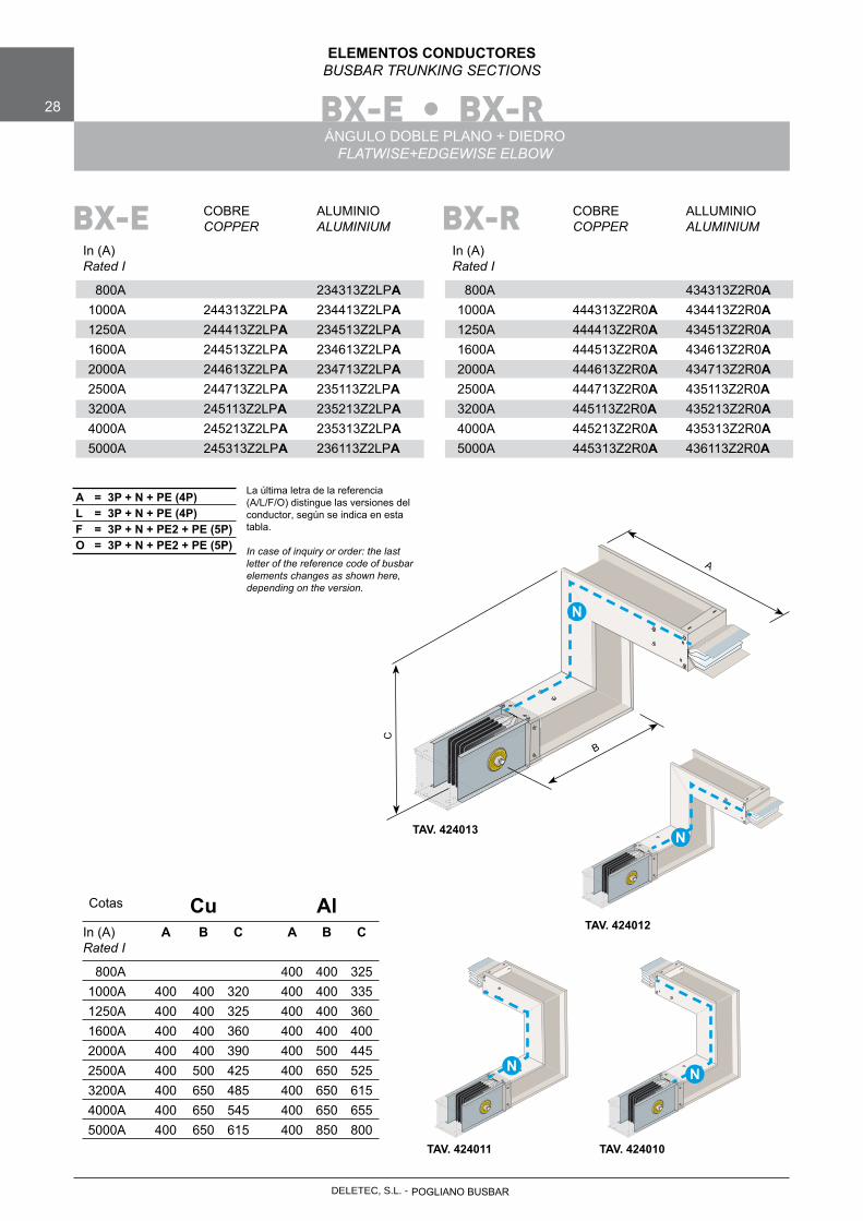
ELEMENTOS CONDUCTORESBUSBAR TRUNKING SECTIONS
ÁNGULO DOBLE PLANO + DIEDROFLATWISE+EDGEWISE ELBOW
COBRE ALUMINIO COPPER ALUMINIUM
In (A)Rated I
800A 234313Z2LPA 1000A 244313Z2LPA 234413Z2LPA 1250A 244413Z2LPA 234513Z2LPA 1600A 244513Z2LPA 234613Z2LPA 2000A 244613Z2LPA 234713Z2LPA 2500A 244713Z2LPA 235113Z2LPA 3200A 245113Z2LPA 235213Z2LPA 4000A 245213Z2LPA 235313Z2LPA 5000A 245313Z2LPA 236113Z2LPA
BX-E
La última letra de la referencia (A/L/F/O) distingue las versiones del conductor, según se indica en esta tabla.
In case of inquiry or order: the last letter of the reference code of busbar elements changes as shown here, depending on the version.
A = 3P + N + PE (4P)L = 3P + N + PE (4P)F = 3P + N + PE2 + PE (5P)O = 3P + N + PE2 + PE (5P)
TAV. 424013
A
B
C
N
Cu Al In (A) A B C A B C Rated I
800A 400 400 325 1000A 400 400 320 400 400 335 1250A 400 400 325 400 400 360 1600A 400 400 360 400 400 400 2000A 400 400 390 400 500 445 2500A 400 500 425 400 650 525 3200A 400 650 485 400 650 615 4000A 400 650 545 400 650 655 5000A 400 650 615 400 850 800
Cotas
N
TAV. 424012
TAV. 424011 TAV. 424010
N N
COBRE ALLUMINIO COPPER ALUMINIUM
In (A)Rated I
800A 434313Z2R0A 1000A 444313Z2R0A 434413Z2R0A 1250A 444413Z2R0A 434513Z2R0A 1600A 444513Z2R0A 434613Z2R0A 2000A 444613Z2R0A 434713Z2R0A 2500A 444713Z2R0A 435113Z2R0A 3200A 445113Z2R0A 435213Z2R0A 4000A 445213Z2R0A 435313Z2R0A 5000A 445313Z2R0A 436113Z2R0A
BX-R
POGLIANO BUSBARDELETEC, S.L. -

DELETEC, S.L. - POGLIANO BUSBAR
BX-E • BX-R 29
ELEMENTOS CONDUCTORESBUSBAR TRUNKING SECTIONS
DOBLE ÁNGULO DIEDRO + PLANOEDGEWISE+FLATWISE ELBOW
COBRE ALUMINIO COPPER ALUMINIUM
In (A)Rated I
800A 234313Z2LPA 1000A 244313Z2LPA 234413Z2LPA 1250A 244413Z2LPA 234513Z2LPA 1600A 244513Z2LPA 234613Z2LPA 2000A 244613Z2LPA 234713Z2LPA 2500A 244713Z2LPA 235113Z2LPA 3200A 245113Z2LPA 235213Z2LPA 4000A 245213Z2LPA 235313Z2LPA 5000A 245313Z2LPA 236113Z2LPA
BX-E
La última letra de la referencia (A/L/F/O) distingue las versiones del conductor, según se indica en esta tabla.
In case of inquiry or order: the last letter of the reference code of busbar elements changes as shown here, depending on the version.
A = 3P + N + PE (4P)L = 3P + N + PE (4P)F = 3P + N + PE2 + PE (5P)O = 3P + N + PE2 + PE (5P)
Cu Al In (A) A B C A B C Rated I
800A 400 400 325 1000A 400 400 320 400 400 335 1250A 400 400 325 400 400 360 1600A 400 400 360 400 400 400 2000A 400 400 390 400 500 445 2500A 400 500 425 400 650 525 3200A 400 650 485 400 650 615 4000A 400 650 545 400 650 655 5000A 400 650 615 400 850 800
Cotas
N
TAV. 424011
TAV. 424012 TAV. 424013
N
N
TAV. 424010
C
A
BN
COBRE ALUMINIO COPPER ALUMINIUM
In (A)Rated I
800A 434313Z2R0A 1000A 444313Z2R0A 434413Z2R0A 1250A 444413Z2R0A 434513Z2R0A 1600A 444513Z2R0A 434613Z2R0A 2000A 444613Z2R0A 434713Z2R0A 2500A 444713Z2R0A 435113Z2R0A 3200A 445113Z2R0A 435213Z2R0A 4000A 445213Z2R0A 435313Z2R0A 5000A 445313Z2R0A 435313Z2R0A
BX-R
BX-E • BX-R30
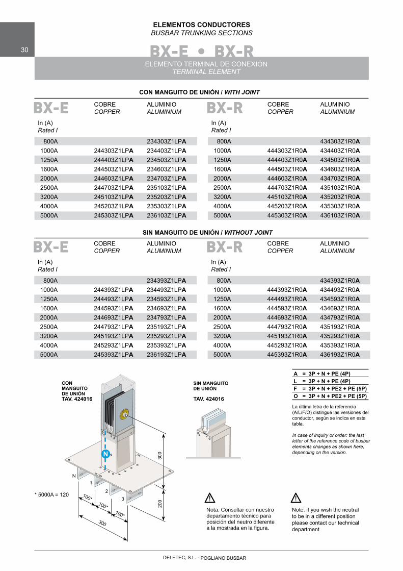
ELEMENTOS CONDUCTORESBUSBAR TRUNKING SECTIONS
ELEMENTO TERMINAL DE CONEXIÓNTERMINAL ELEMENT
COBRE ALUMINIO COPPER ALUMINIUM
In (A)Rated I
800A 234303Z1LPA 1000A 244303Z1LPA 234403Z1LPA 1250A 244403Z1LPA 234503Z1LPA 1600A 244503Z1LPA 234603Z1LPA 2000A 244603Z1LPA 234703Z1LPA 2500A 244703Z1LPA 235103Z1LPA 3200A 245103Z1LPA 235203Z1LPA 4000A 245203Z1LPA 235303Z1LPA 5000A 245303Z1LPA 236103Z1LPA
BX-E
La última letra de la referencia (A/L/F/O) distingue las versiones del conductor, según se indica en esta tabla.
In case of inquiry or order: the last letter of the reference code of busbar elements changes as shown here, depending on the version.
A = 3P + N + PE (4P)L = 3P + N + PE (4P)F = 3P + N + PE2 + PE (5P)O = 3P + N + PE2 + PE (5P)
Nota: Consultar con nuestro departamento técnico para posición del neutro diferente a la mostrada en la figura.
Note: if you wish the neutral to be in a different position please contact our technical department
! !
TAV. 424016
300
300
N
200
100*100*
100*
N1
23
COBRE ALUMINIO COPPER ALUMINIUM
In (A)Rated I
800A 434303Z1R0A 1000A 444303Z1R0A 434403Z1R0A 1250A 444403Z1R0A 434503Z1R0A 1600A 444503Z1R0A 434603Z1R0A 2000A 444603Z1R0A 434703Z1R0A 2500A 444703Z1R0A 435103Z1R0A 3200A 445103Z1R0A 435203Z1R0A 4000A 445203Z1R0A 435303Z1R0A 5000A 445303Z1R0A 436103Z1R0A
BX-R
* 5000A = 120
TAV. 424016
COBRE ALUMINIO COPPER ALUMINIUM
In (A)Rated I
800A 234393Z1LPA 1000A 244393Z1LPA 234493Z1LPA 1250A 244493Z1LPA 234593Z1LPA 1600A 244593Z1LPA 234693Z1LPA 2000A 244693Z1LPA 234793Z1LPA 2500A 244793Z1LPA 235193Z1LPA 3200A 245193Z1LPA 235293Z1LPA 4000A 245293Z1LPA 235393Z1LPA 5000A 245393Z1LPA 236193Z1LPA
BX-E COBRE ALUMINIO COPPER ALUMINIUM
In (A)Rated I
800A 434393Z1R0A 1000A 444393Z1R0A 434493Z1R0A 1250A 444493Z1R0A 434593Z1R0A 1600A 444593Z1R0A 434693Z1R0A 2000A 444693Z1R0A 434793Z1R0A 2500A 444793Z1R0A 435193Z1R0A 3200A 445193Z1R0A 435293Z1R0A 4000A 445293Z1R0A 435393Z1R0A 5000A 445393Z1R0A 436193Z1R0A
BX-R
CON MANGUITO DE UNIÓN / WITH JOINT
SIN MANGUITO DE UNIÓN / WITHOUT JOINT
CON MANGUITO DE UNIÓN
SIN MANGUITO DE UNIÓN
POGLIANO BUSBARDELETEC, S.L. -
DELETEC, S.L. - POGLIANO BUSBAR
BX-E • BX-R 31
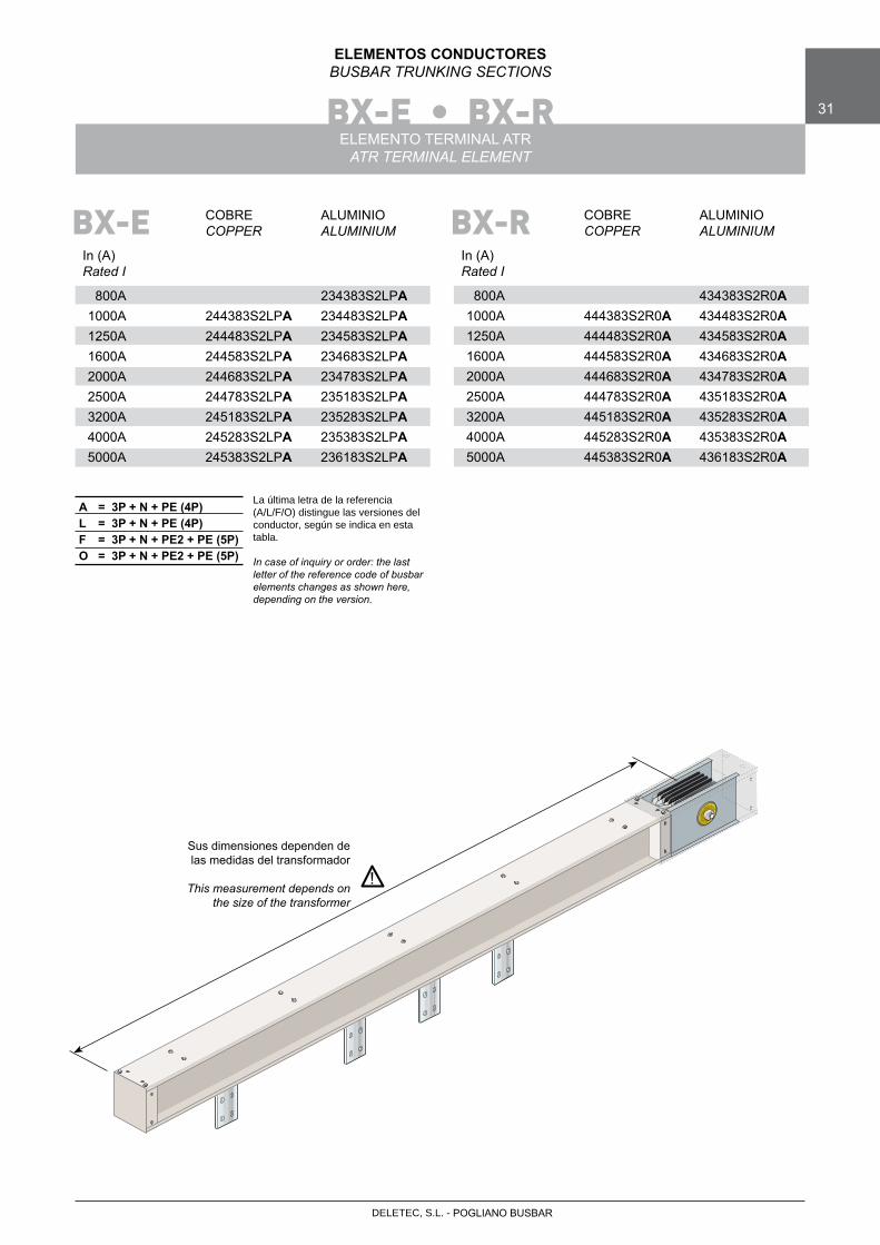
ELEMENTOS CONDUCTORESBUSBAR TRUNKING SECTIONS
ELEMENTO TERMINAL ATR ATR TERMINAL ELEMENT
COBRE ALUMINIO COPPER ALUMINIUM
In (A)Rated I
800A 234383S2LPA 1000A 244383S2LPA 234483S2LPA 1250A 244483S2LPA 234583S2LPA 1600A 244583S2LPA 234683S2LPA 2000A 244683S2LPA 234783S2LPA 2500A 244783S2LPA 235183S2LPA 3200A 245183S2LPA 235283S2LPA 4000A 245283S2LPA 235383S2LPA 5000A 245383S2LPA 236183S2LPA
BX-E
La última letra de la referencia (A/L/F/O) distingue las versiones del conductor, según se indica en esta tabla.
In case of inquiry or order: the last letter of the reference code of busbar elements changes as shown here, depending on the version.
A = 3P + N + PE (4P)L = 3P + N + PE (4P)F = 3P + N + PE2 + PE (5P)O = 3P + N + PE2 + PE (5P)
Sus dimensiones dependen de las medidas del transformador
This measurement depends onthe size of the transformer
!
COBRE ALUMINIO COPPER ALUMINIUM
In (A)Rated I
800A 434383S2R0A 1000A 444383S2R0A 434483S2R0A 1250A 444483S2R0A 434583S2R0A 1600A 444583S2R0A 434683S2R0A 2000A 444683S2R0A 434783S2R0A 2500A 444783S2R0A 435183S2R0A 3200A 445183S2R0A 435283S2R0A 4000A 445283S2R0A 435383S2R0A 5000A 445383S2R0A 436183S2R0A
BX-R
BX-E • BX-R32
ELEMENTOS CONDUCTORESBUSBAR TRUNKING SECTIONS
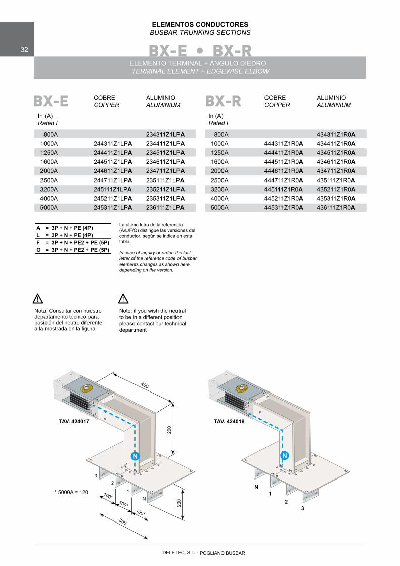
ELEMENTO TERMINAL + ÁNGULO DIEDROTERMINAL ELEMENT + EDGEWISE ELBOW
COBRE ALUMINIO COPPER ALUMINIUM
In (A)Rated I
800A 234311Z1LPA 1000A 244311Z1LPA 234411Z1LPA 1250A 244411Z1LPA 234511Z1LPA 1600A 244511Z1LPA 234611Z1LPA 2000A 244611Z1LPA 234711Z1LPA 2500A 244711Z1LPA 235111Z1LPA 3200A 245111Z1LPA 235211Z1LPA 4000A 245211Z1LPA 235311Z1LPA 5000A 245311Z1LPA 236111Z1LPA
La última letra de la referencia (A/L/F/O) distingue las versiones del conductor, según se indica en esta tabla.
In case of inquiry or order: the last letter of the reference code of busbar elements changes as shown here, depending on the version.
A = 3P + N + PE (4P)L = 3P + N + PE (4P)F = 3P + N + PE2 + PE (5P)O = 3P + N + PE2 + PE (5P)
BX-E COBRE ALUMINIO COPPER ALUMINIUM
In (A)Rated I
800A 434311Z1R0A 1000A 444311Z1R0A 434411Z1R0A 1250A 444411Z1R0A 434511Z1R0A 1600A 444511Z1R0A 434611Z1R0A 2000A 444611Z1R0A 434711Z1R0A 2500A 444711Z1R0A 435111Z1R0A 3200A 445111Z1R0A 435211Z1R0A 4000A 445211Z1R0A 435311Z1R0A 5000A 445311Z1R0A 436111Z1R0A
BX-R
Nota: Consultar con nuestro departamento técnico para posición del neutro diferente a la mostrada en la figura.
Note: if you wish the neutral to be in a different position please contact our technical department
! !
TAV. 424017
200
300
200
100*100*
100*
32
1N
400
N
TAV. 424018
N
N1
23
* 5000A = 120
POGLIANO BUSBARDELETEC, S.L. -
DELETEC, S.L. - POGLIANO BUSBAR
BX-E • BX-R 33
ELEMENTOS CONDUCTORESBUSBAR TRUNKING SECTIONS
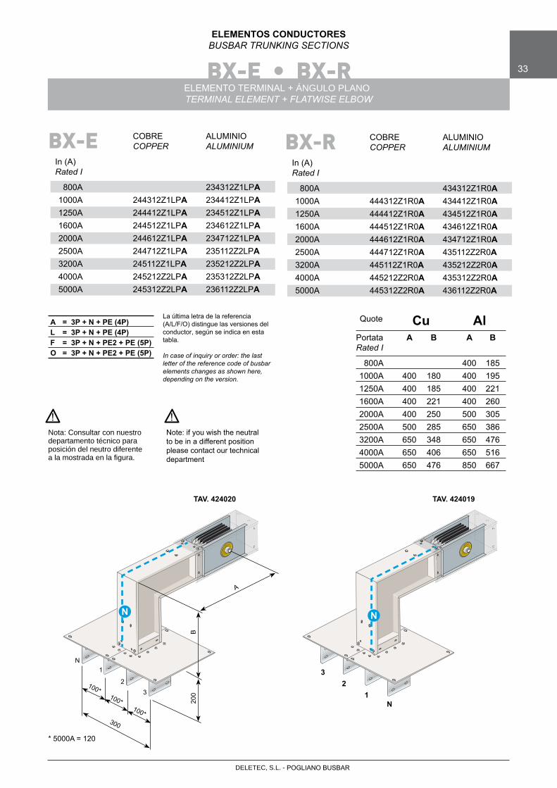
ELEMENTO TERMINAL + ÁNGULO PLANOTERMINAL ELEMENT + FLATWISE ELBOW
COBRE ALUMINIO COPPER ALUMINIUM
In (A)Rated I
800A 234312Z1LPA 1000A 244312Z1LPA 234412Z1LPA 1250A 244412Z1LPA 234512Z1LPA 1600A 244512Z1LPA 234612Z1LPA 2000A 244612Z1LPA 234712Z1LPA 2500A 244712Z1LPA 235112Z2LPA 3200A 245112Z1LPA 235212Z2LPA 4000A 245212Z2LPA 235312Z2LPA 5000A 245312Z2LPA 236112Z2LPA
La última letra de la referencia (A/L/F/O) distingue las versiones del conductor, según se indica en esta tabla.
In case of inquiry or order: the last letter of the reference code of busbar elements changes as shown here, depending on the version.
A = 3P + N + PE (4P)L = 3P + N + PE (4P)F = 3P + N + PE2 + PE (5P)O = 3P + N + PE2 + PE (5P)
BX-E
Nota: Consultar con nuestro departamento técnico para posición del neutro diferente a la mostrada en la figura.
Note: if you wish the neutral to be in a different position please contact our technical department
! !
TAV. 424020
300
200
100*100*
100*
N1
23
B
A
N
TAV. 424019
N
Cu Al Portata A B A B Rated I
800A 400 185 1000A 400 180 400 195 1250A 400 185 400 221 1600A 400 221 400 260 2000A 400 250 500 305 2500A 500 285 650 386 3200A 650 348 650 476 4000A 650 406 650 516 5000A 650 476 850 667
Quote
COBRE ALUMINIO COPPER ALUMINIUM
In (A)Rated I
800A 434312Z1R0A 1000A 444312Z1R0A 434412Z1R0A 1250A 444412Z1R0A 434512Z1R0A 1600A 444512Z1R0A 434612Z1R0A 2000A 444612Z1R0A 434712Z1R0A 2500A 444712Z1R0A 435112Z2R0A 3200A 445112Z1R0A 435212Z2R0A 4000A 445212Z2R0A 435312Z2R0A 5000A 445312Z2R0A 436112Z2R0A
BX-R
32
1N
* 5000A = 120
BX-E • BX-R34
ELEMENTOS CONDUCTORESBUSBAR TRUNKING SECTIONS
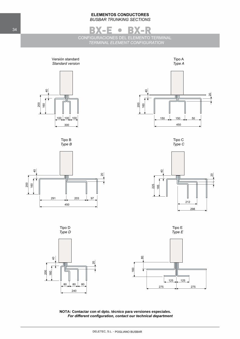
CONFIGURACIONES DEL ELEMENTO TERMINALTERMINAL ELEMENT CONFIGURATION
Versión standardStandard version
Tipo AType A
Tipo BType B
Tipo CType C
Tipo DType D
Tipo EType E
100 100 100
300
200
160
40
150 150 50
450
200
160
40
20
291 203 97
450
200
160
40
20
212
298
225
185
40
20
80 80 80
240
200
160
40
20
275
125 125
275
160
80
NOTA: Contactar con el dpto. técnico para versiones especiales.For different configuration, contact our technical department
POGLIANO BUSBARDELETEC, S.L. -
DELETEC, S.L. - POGLIANO BUSBAR
BX-E • BX-R 35
ELEMENTOS CONDUCTORESBUSBAR TRUNKING SECTIONS
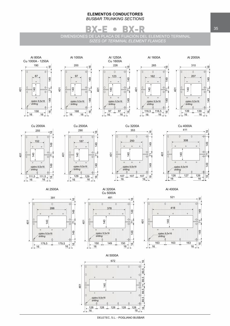
DIMENSIONES DE LA PLACA DE FIJACIÓN DEL ELEMENTO TERMINALSIZES OF TERMINAL ELEMENT FLANGES
Al 800ACu 1000A - 1250A
Al 1000A Al 1250ACu 1600A
Al 1600A Al 2000A
Cu 2000A Cu 2500A Cu 3200A Cu 4000A
Al 2500A Al 3200ACu 5000A
Al 4000A
158
401
16 16
140
149
149
7116
16
87
190
168
401
16 16
140
149
149
7116
16
97
200
97
401
16 1614
0
149
149
7116
16
123
226
97
ojales 9,5x16drilling
ojales 9,5x16drilling
ojales 9,5x16drilling
116,5
401
16 16
140
149
149
7116
16
162
265
116,5
ojales 9,5x16drilling
139
401
16 16
140
149
149
7116
16
207
310
139
ojales 9,5x16drilling
111,5
401
16 16
140
149
149
7116
16
152
255
111,5
ojales 9,5x16drilling
129
401
16 16
140
149
149
7116
16
187
290
129
ojales 9,5x16drilling
107
401
16 16
140
149
149
7116
16
250
353
107
ojales 9,5x16drilling
107 126
401
16 1614
0
149
149
7116
16
308
411
127
ojales 9,5x16drilling
126
179,5
401
16 16
140
149
149
7116
16
288
391
ojales 9,5x16drilling
179,5 150
401
16 16
140
149
149
7116
16
378
481
ojales 9,5x16drilling
149 150 163
401
16 16
140
149
149
7116
16
418
521
ojales 9,5x16drilling
163 163
Al 5000A
128
461
16 16
89,5
89,5
7116
16
672
ojales 9,5x16drilling
128 128
89,5
89,5
128128
140
BX-E • BX-R36
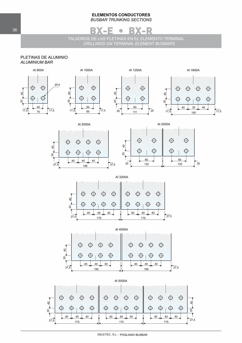
ELEMENTOS CONDUCTORESBUSBAR TRUNKING SECTIONS
TALADROS DE LAS PLETINAS EN EL ELEMENTO TERMINALDRILLINGS ON TERMINAL ELEMENT BUSBARS
PLETINAS DE ALUMINIOALUMINIUM BAR
Al 800A Al 1000A Al 1250A Al 1600A
Al 2000A Al 2500A
Al 3200A
Al 4000A
17,540
17,575
2040
Ø14
17,550
17,585
2040
2560
2511120
4017,5
4017,5150
2040
35 40
37,540
37,5195
2040
40 4035
6035130
2040
60130
27,540
27,5175
2040
40 40 40
175
40 40
40
195
40 40 40
195
40 4037,5
2040
37,5
Al 5000A
27,540
27,5175
2040
40 40 40
175
40 40 40
175
40 40
2040
POGLIANO BUSBARDELETEC, S.L. -
DELETEC, S.L. - POGLIANO BUSBAR
BX-E • BX-R 37
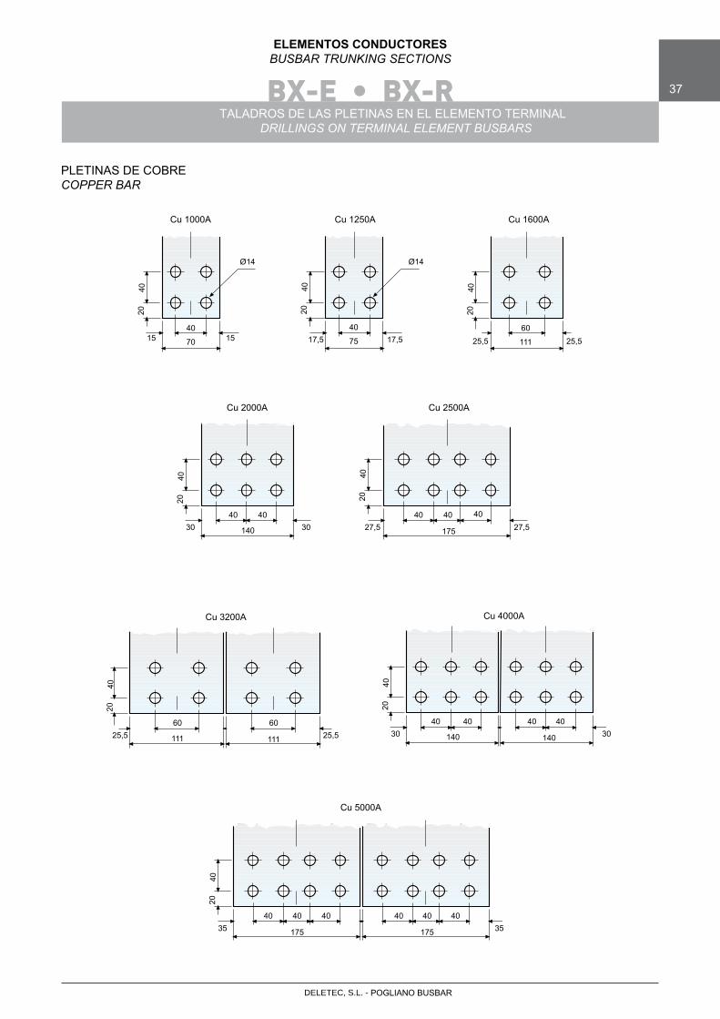
ELEMENTOS CONDUCTORESBUSBAR TRUNKING SECTIONS
TALADROS DE LAS PLETINAS EN EL ELEMENTO TERMINALDRILLINGS ON TERMINAL ELEMENT BUSBARS
PLETINAS DE COBRECOPPER BAR
Cu 1000A Cu 1250A Cu 1600A
Cu 2000A Cu 2500A
Cu 3200A Cu 4000A
Cu 5000A
1540
1570
2040
Ø14
17,540
17,575
2040
Ø14
25,560
25,5111
2040
3040
30140
2040
4027,5
4027,5175
2040
40 40
25,560
25,5111
2040
60
11130
4030140
2040
40
140
40 40
3540
35175
2040
40
175
40 40 40 40
BX-E • BX-R38
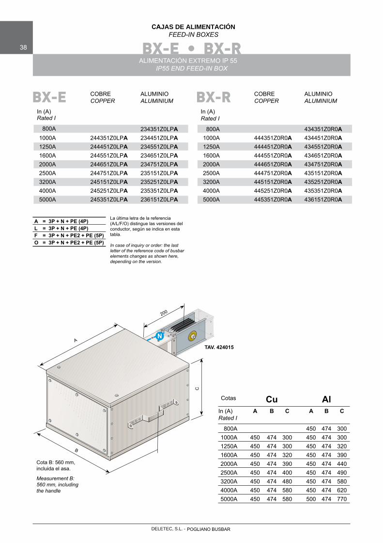
CAJAS DE ALIMENTACIÓNFEED-IN BOXES
ALIMENTACIÓN EXTREMO IP 55IP55 END FEED-IN BOX
COBRE ALUMINIO COPPER ALUMINIUM
In (A)Rated I
800A 234351Z0LPA 1000A 244351Z0LPA 234451Z0LPA 1250A 244451Z0LPA 234551Z0LPA 1600A 244551Z0LPA 234651Z0LPA 2000A 244651Z0LPA 234751Z0LPA 2500A 244751Z0LPA 235151Z0LPA 3200A 245151Z0LPA 235251Z0LPA 4000A 245251Z0LPA 235351Z0LPA 5000A 245351Z0LPA 236151Z0LPA
BX-E
La última letra de la referencia (A/L/F/O) distingue las versiones del conductor, según se indica en esta tabla.
In case of inquiry or order: the last letter of the reference code of busbar elements changes as shown here, depending on the version.
A = 3P + N + PE (4P)L = 3P + N + PE (4P)F = 3P + N + PE2 + PE (5P)O = 3P + N + PE2 + PE (5P)
Cu Al In (A) A B C A B C Rated I
800A 450 474 300 1000A 450 474 300 450 474 300 1250A 450 474 300 450 474 320 1600A 450 474 320 450 474 390 2000A 450 474 390 450 474 440 2500A 450 474 400 450 474 490 3200A 450 474 480 450 474 580 4000A 450 474 580 450 474 620 5000A 450 474 580 500 474 770
Cotas
B
A
C
N
200
Cota B: 560 mm, incluida el asa.
Measurement B:560 mm, includingthe handle
TAV. 424015
COBRE ALUMINIO COPPER ALUMINIUM
In (A)Rated I
800A 434351Z0R0A 1000A 444351Z0R0A 434451Z0R0A 1250A 444451Z0R0A 434551Z0R0A 1600A 444551Z0R0A 434651Z0R0A 2000A 444651Z0R0A 434751Z0R0A 2500A 444751Z0R0A 435151Z0R0A 3200A 445151Z0R0A 435251Z0R0A 4000A 445251Z0R0A 435351Z0R0A 5000A 445351Z0R0A 436151Z0R0A
BX-R
POGLIANO BUSBARDELETEC, S.L. -
DELETEC, S.L. - POGLIANO BUSBAR
BX-E 39
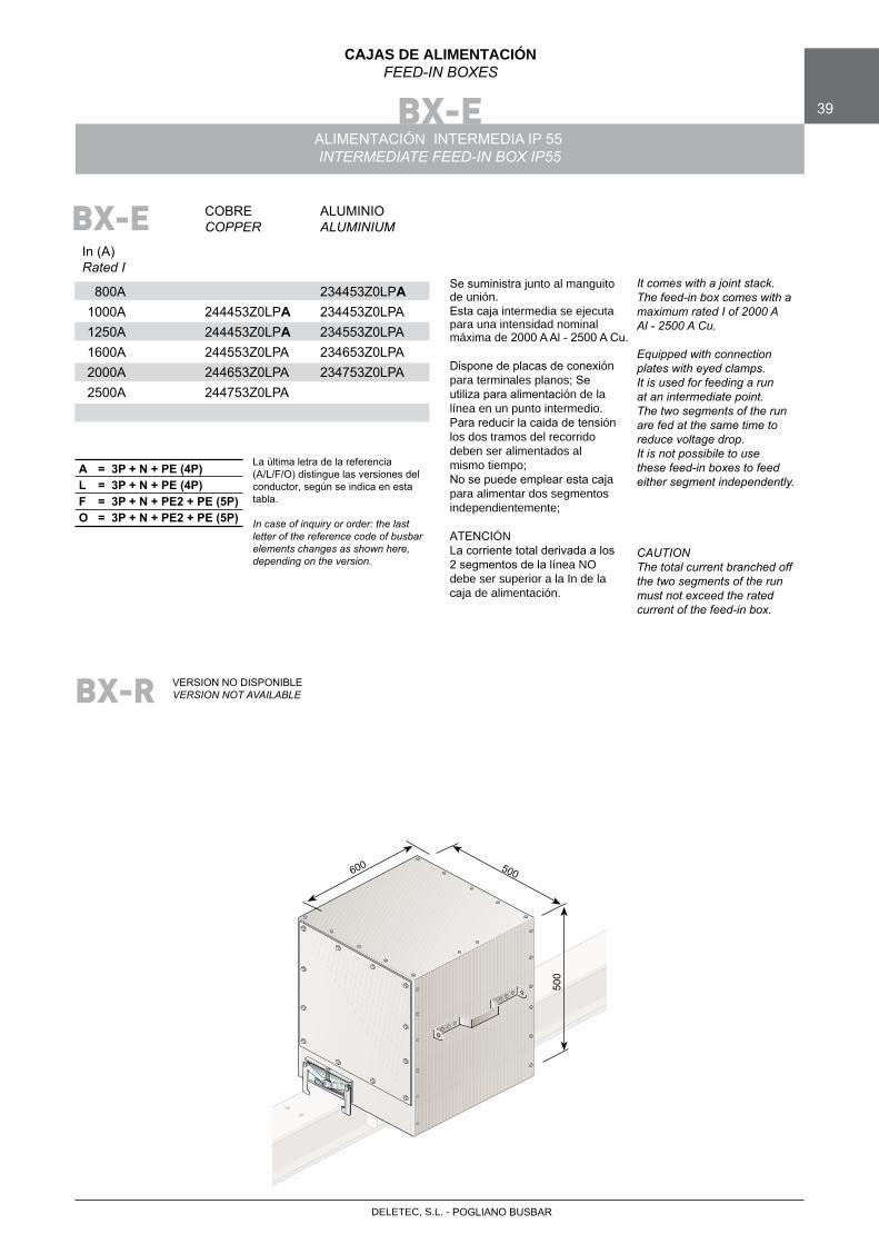
CAJAS DE ALIMENTACIÓNFEED-IN BOXES
ALIMENTACIÓN INTERMEDIA IP 55INTERMEDIATE FEED-IN BOX IP55
COBRE ALUMINIO COPPER ALUMINIUM
In (A)Rated I
800A 234453Z0LPA 1000A 244453Z0LPA 234453Z0LPA 1250A 244453Z0LPA 234553Z0LPA 1600A 244553Z0LPA 234653Z0LPA 2000A 244653Z0LPA 234753Z0LPA 2500A 244753Z0LPA
BX-E
La última letra de la referencia (A/L/F/O) distingue las versiones del conductor, según se indica en esta tabla.
In case of inquiry or order: the last letter of the reference code of busbar elements changes as shown here, depending on the version.
A = 3P + N + PE (4P)L = 3P + N + PE (4P)F = 3P + N + PE2 + PE (5P)O = 3P + N + PE2 + PE (5P)
500600
500
Se suministra junto al manguito de unión.Esta caja intermedia se ejecuta para una intensidad nominal máxima de 2000 A Al - 2500 A Cu.
Dispone de placas de conexiónpara terminales planos; Se utiliza para alimentación de lalínea en un punto intermedio. Para reducir la caida de tensión los dos tramos del recorrido deben ser alimentados al mismo tiempo;No se puede emplear esta caja para alimentar dos segmentos independientemente;
ATENCIÓNLa corriente total derivada a los 2 segmentos de la línea NO debe ser superior a la In de lacaja de alimentación.
It comes with a joint stack. The feed-in box comes with a maximum rated I of 2000 A Al - 2500 A Cu.
Equipped with connection plates with eyed clamps.It is used for feeding a run at an intermediate point.The two segments of the run are fed at the same time to reduce voltage drop.It is not possibile to use these feed-in boxes to feed either segment independently.
CAUTIONThe total current branched off the two segments of the run must not exceed the rated current of the feed-in box.
BX-R VERSION NO DISPONIBLEVERSION NOT AVAILABLE
BX-E40
CAJAS DE DERIVACIÓNTAP-OFF UNITS
CAJAS DE DERIVACIÓN PLUG-INPLUG-IN TAP-OFF UNITS
B
A
C
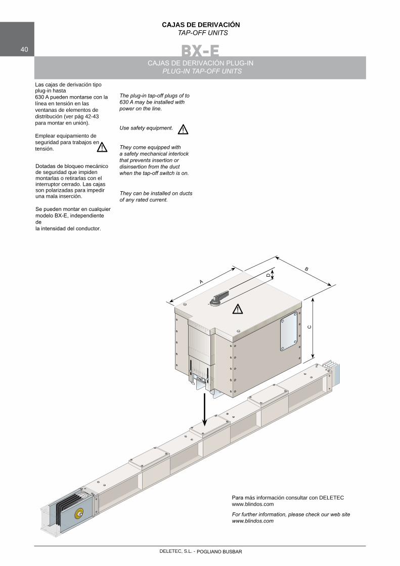
Las cajas de derivación tipo plug-in hasta630 A pueden montarse con la línea en tensión en las ventanas de elementos de distribución (ver pág 42-43 para montar en unión). Emplear equipamiento de seguridad para trabajos en tensión.
Dotadas de bloqueo mecánico de seguridad que impiden montarlas o retirarlas con el interruptor cerrado. Las cajas son polarizadas para impediruna mala inserción.
Se pueden montar en cualquier modelo BX-E, independiente de la intensidad del conductor.
The plug-in tap-off plugs of to 630 A may be installed with power on the line.
Use safety equipment.
They come equipped with a safety mechanical interlock that prevents insertion or disinsertion from the duct when the tap-off switch is on.
They can be installed on ducts of any rated current.
D
Para más información consultar con DELETECwww.blindos.com
For further information, please check our web site www.blindos.com
!
!
!
POGLIANO BUSBARDELETEC, S.L. -
DELETEC, S.L. - POGLIANO BUSBAR
BX-E 41
CAJAS DE DERIVACIÓNTAP-OFF UNITS
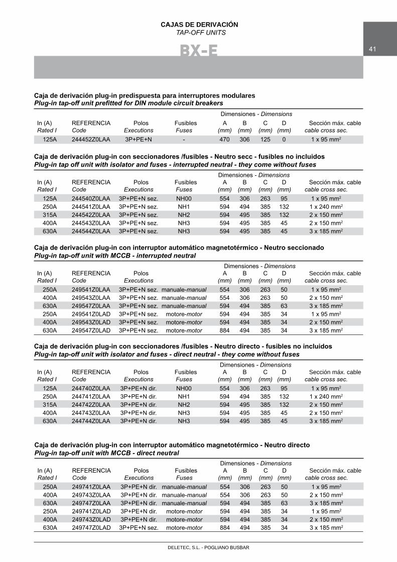
Dimensiones - Dimensions In (A) REFERENCIA Polos Fusibles A B C D Sección máx. cable Rated I Code Executions Fuses (mm) (mm) (mm) (mm) cable cross sec. 125A 244452Z0LAA 3P+PE+N - 470 306 125 0 1 x 95 mm2
Caja de derivación plug-in predispuesta para interruptores modularesPlug-in tap-off unit prefitted for DIN module circuit breakers
Dimensiones - Dimensions In (A) REFERENCIA Polos Fusibles A B C D Sección máx. cable Rated I Code Executions Fuses (mm) (mm) (mm) (mm) cable cross sec. 125A 244540Z0LAA 3P+PE+N sez. NH00 554 306 263 95 1 x 95 mm2
250A 244541Z0LAA 3P+PE+N sez. NH1 594 494 385 132 1 x 240 mm2
315A 244542Z0LAA 3P+PE+N sez. NH2 594 495 385 132 2 x 150 mm2
400A 244543Z0LAA 3P+PE+N sez. NH3 594 495 385 45 2 x 150 mm2
630A 244544Z0LAA 3P+PE+N sez. NH3 594 495 385 45 3 x 185 mm2
Caja de derivación plug-in con seccionadores /fusibles - Neutro secc - fusibles no incluidosPlug-in tap off unit with isolator and fuses - interrupted neutral - they come without fuses
Dimensiones - Dimensions In (A) REFERENCIA Polos A B C D Sección máx. cable Rated I Code Executions (mm) (mm) (mm) (mm) cable cross sec. 250A 249541Z0LAA 3P+PE+N sez. manuale-manual 554 306 263 50 1 x 95 mm2
400A 249543Z0LAA 3P+PE+N sez. manuale-manual 554 306 263 50 2 x 150 mm2
630A 249547Z0LAA 3P+PE+N sez. manuale-manual 594 494 385 63 3 x 185 mm2
250A 249541Z0LAD 3P+PE+N sez. motore-motor 594 494 385 34 1 x 95 mm2
400A 249543Z0LAD 3P+PE+N sez. motore-motor 594 494 385 34 2 x 150 mm2
630A 249547Z0LAD 3P+PE+N sez. motore-motor 884 494 385 34 3 x 185 mm2
Caja de derivación plug-in con interruptor automático magnetotérmico - Neutro seccionadoPlug-in tap-off unit with MCCB - interrupted neutral
Dimensiones - Dimensions In (A) REFERENCIA Polos Fusibles A B C D Sección máx. cable Rated I Code Executions Fuses (mm) (mm) (mm) (mm) cable cross sec. 125A 244740Z0LAA 3P+PE+N dir. NH00 554 306 263 95 1 x 95 mm2
250A 244741Z0LAA 3P+PE+N dir. NH1 594 494 385 132 1 x 240 mm2
315A 244742Z0LAA 3P+PE+N dir. NH2 594 495 385 132 2 x 150 mm2
400A 244743Z0LAA 3P+PE+N dir. NH3 594 495 385 45 2 x 150 mm2
630A 244744Z0LAA 3P+PE+N dir. NH3 594 495 385 45 3 x 185 mm2
Caja de derivación plug-in con seccionadores /fusibles - Neutro directo - fusibles no incluidosPlug-in tap-off unit with isolator and fuses - direct neutral - they come without fuses
Dimensiones - Dimensions In (A) REFERENCIA Polos Fusibles A B C D Sección máx. cable Rated I Code Executions Fuses (mm) (mm) (mm) (mm) cable cross sec. 250A 249741Z0LAA 3P+PE+N dir. manuale-manual 554 306 263 50 1 x 95 mm2
400A 249743Z0LAA 3P+PE+N dir. manuale-manual 554 306 263 50 2 x 150 mm2
630A 249747Z0LAA 3P+PE+N dir. manuale-manual 594 494 385 63 3 x 185 mm2
250A 249741Z0LAD 3P+PE+N dir. motore-motor 594 494 385 34 1 x 95 mm2
400A 249743Z0LAD 3P+PE+N dir. motore-motor 594 494 385 34 2 x 150 mm2
630A 249747Z0LAD 3P+PE+N sez. motore-motor 884 494 385 34 3 x 185 mm2
Caja de derivación plug-in con interruptor automático magnetotérmico - Neutro directoPlug-in tap-off unit with MCCB - direct neutral
BX-E42
CAJAS DE DERIVACIÓNTAP-OFF UNITS
CAJAS DE DERIVACIÓN EN UNIÓNJOINT TAP-OFF PLUGS
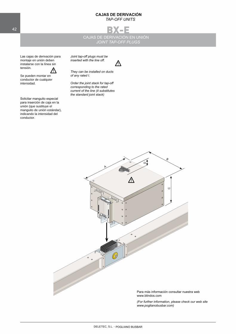
Las cajas de derivación para montaje en unión deben instalarse con la línea sintensión.
Se pueden montar en conductor de cualquier intensidad.
Solicitar manguito especial para inserción de caja en la unión (que sustituye el manguito de unión estándar), indicando la intensidad del conductor.
Joint tap-off plugs must be inserted with the line off.
They can be installed on ducts of any rated I.
Order the joint stack for tap-off corresponding to the rated current of the line (it substitutes the standard joint stack)
B
AC
D
!
Para más información consultar nuestra web www.blindos.com
(For further information, please check our web site www.poglianobusbar.com)
POGLIANO BUSBARDELETEC, S.L. -
!!
DELETEC, S.L. - POGLIANO BUSBAR
BX-E 43
CAJAS DE DERIVACIÓNTAP-OFF UNITS
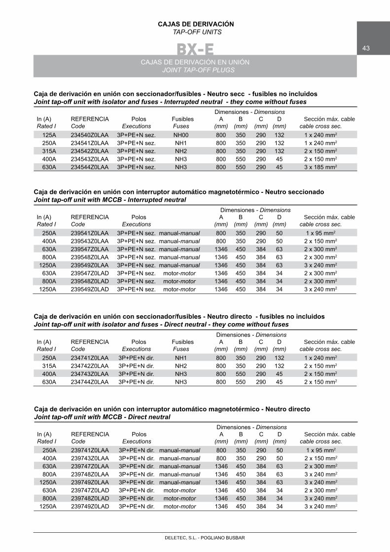
Dimensiones - Dimensions In (A) REFERENCIA Polos Fusibles A B C D Sección máx. cable Rated I Code Executions Fuses (mm) (mm) (mm) (mm) cable cross sec. 125A 234540Z0LAA 3P+PE+N sez. NH00 800 350 290 132 1 x 240 mm2
250A 234541Z0LAA 3P+PE+N sez. NH1 800 350 290 132 1 x 240 mm2
315A 234542Z0LAA 3P+PE+N sez. NH2 800 350 290 132 2 x 150 mm2
400A 234543Z0LAA 3P+PE+N sez. NH3 800 550 290 45 2 x 150 mm2
630A 234544Z0LAA 3P+PE+N sez. NH3 800 550 290 45 3 x 185 mm2
Caja de derivación en unión con seccionador/fusibles - Neutro secc - fusibles no incluidosJoint tap-off unit with isolator and fuses - Interrupted neutral - they come without fuses
Dimensiones - Dimensions In (A) REFERENCIA Polos A B C D Sección máx. cable Rated I Code Executions (mm) (mm) (mm) (mm) cable cross sec. 250A 239541Z0LAA 3P+PE+N sez. manual-manual 800 350 290 50 1 x 95 mm2
400A 239543Z0LAA 3P+PE+N sez. manual-manual 800 350 290 50 2 x 150 mm2
630A 239547Z0LAA 3P+PE+N sez. manual-manual 1346 450 384 63 2 x 300 mm2
800A 239548Z0LAA 3P+PE+N sez. manual-manual 1346 450 384 63 2 x 300 mm2
1250A 239549Z0LAA 3P+PE+N sez. manual-manual 1346 450 384 63 3 x 240 mm2
630A 239547Z0LAD 3P+PE+N sez. motor-motor 1346 450 384 34 2 x 300 mm2
800A 239548Z0LAD 3P+PE+N sez. motor-motor 1346 450 384 34 2 x 300 mm2
1250A 239549Z0LAD 3P+PE+N sez. motor-motor 1346 450 384 34 3 x 240 mm2
Caja de derivación en unión con interruptor automático magnetotérmico - Neutro seccionadoJoint tap-off unit with MCCB - Interrupted neutral
Dimensiones - Dimensions In (A) REFERENCIA Polos Fusibles A B C D Sección máx. cable Rated I Code Executions Fuses (mm) (mm) (mm) (mm) cable cross sec. 250A 234741Z0LAA 3P+PE+N dir. NH1 800 350 290 132 1 x 240 mm2
315A 234742Z0LAA 3P+PE+N dir. NH2 800 350 290 132 2 x 150 mm2
400A 234743Z0LAA 3P+PE+N dir. NH3 800 550 290 45 2 x 150 mm2
630A 234744Z0LAA 3P+PE+N dir. NH3 800 550 290 45 2 x 150 mm2
Caja de derivación en unión con seccionador/fusibles - Neutro directo - fusibles no incluidosJoint tap-off unit with isolator and fuses - Direct neutral - they come without fuses
Dimensiones - Dimensions In (A) REFERENCIA Polos A B C D Sección máx. cable Rated I Code Executions (mm) (mm) (mm) (mm) cable cross sec. 250A 239741Z0LAA 3P+PE+N dir. manual-manual 800 350 290 50 1 x 95 mm2
400A 239743Z0LAA 3P+PE+N dir. manual-manual 800 350 290 50 2 x 150 mm2
630A 239747Z0LAA 3P+PE+N dir. manual-manual 1346 450 384 63 2 x 300 mm2
800A 239748Z0LAA 3P+PE+N dir. manual-manual 1346 450 384 63 3 x 240 mm2
1250A 239749Z0LAA 3P+PE+N dir. manual-manual 1346 450 384 63 3 x 240 mm2
630A 239747Z0LAD 3P+PE+N dir. motor-motor 1346 450 384 34 2 x 300 mm2
800A 239748Z0LAD 3P+PE+N dir. motor-motor 1346 450 384 34 3 x 240 mm2
1250A 239749Z0LAD 3P+PE+N dir. motor-motor 1346 450 384 34 3 x 240 mm2
Caja de derivación en unión con interruptor automático magnetotérmico - Neutro directoJoint tap-off unit with MCCB - Direct neutral
ÓN EN UNIÓNCAJAS DE DERIVACIJOINT TAP-OFF PLUGS
BX-E44
CAJAS DE DERIVACIÓNTAP-OFF UNITS
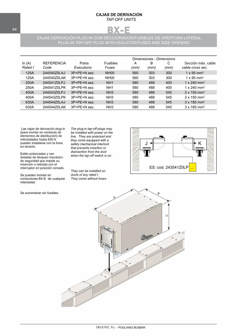
CAJAS DERIVACIÓN PLUG-IN CON SECCIONADOR/FUSIBLES DE APERTURA LATERALPLUG-IN TAP-OFF PLUG WITH ISOLATOR/FUSES AND SIDE OPENING
Las cajas de derivación plug-in
(para montar en ventanas de elementos de distribución) de intensidades hasta 630 A pueden instalarse con la línea en tensión.
Están polarizadas y van dotadas de bloqueo mecánico de seguridad que impide su inserción o retirada con el interruptor en posición cerrado.
Se pueden montar en conductores BX-E de cualquier intensidad.
Se suministran sin fusibles.
The plug-in tap-off plugs may be installed with power on the line. They are polarized and they come equipped with a safety mechanical interlock that prevents insertion or disinsertion from the duct when the tap-off switch is on.
They can be installed on ducts of any rated I. They come without fuses.
B
A
C
Dimensiones - Dimensions In (A) REFERENCIA Polos Fusibles A B C Sección máx. cable Rated I Code Executions Fuses (mm) (mm) (mm) cable cross sec. 125A 244540Z0LAJ 3P+PE+N sez. NH00 560 303 300 1 x 95 mm2
125A 244540Z0LAK 3P+PE+N sez. NH00 560 303 300 1 x 95 mm2
250A 244541Z0LPJ 3P+PE+N sez. NH1 580 488 400 1 x 240 mm2
250A 244541Z0LPK 3P+PE+N sez. NH1 580 488 400 1 x 240 mm2
400A 244543Z0LPJ 3P+PE+N sez. NH3 580 488 545 2 x 150 mm2
400A 244543Z0LPK 3P+PE+N sez. NH3 580 488 545 2 x 150 mm2
630A 244544Z0LAJ 3P+PE+N sez. NH3 580 488 545 3 x 185 mm2
630A 244544Z0LAK 3P+PE+N sez. NH3 580 488 545 3 x 185 mm2
J K
ES: cod. 243541Z0LP ...
POGLIANO BUSBARDELETEC, S.L. -
DELETEC, S.L. - POGLIANO BUSBAR
45
CAJAS DE DERIVACIÓNTAP-OFF UNITS
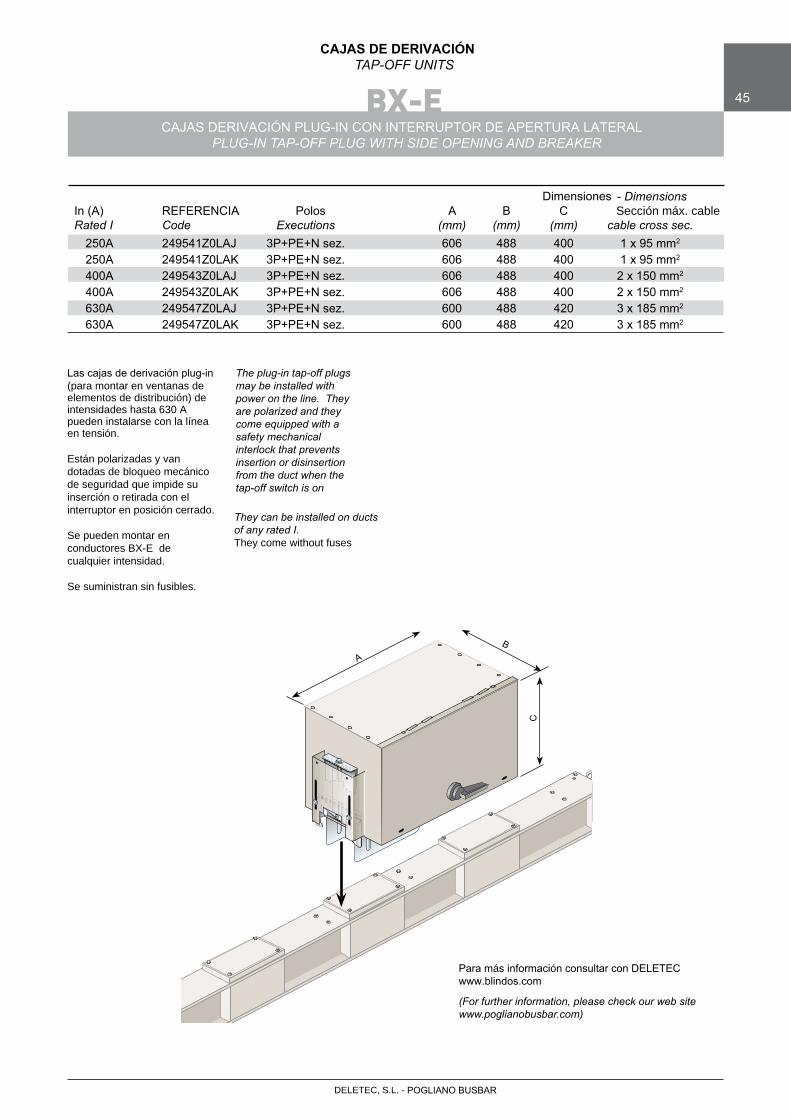
BX-ECAJAS DERIVACIÓN PLUG-IN CON INTERRUPTOR DE APERTURA LATERAL
PLUG-IN TAP-OFF PLUG WITH SIDE OPENING AND BREAKER
Las cajas de derivación plug-in(para montar en ventanas de elementos de distribución) de intensidades hasta 630 A pueden instalarse con la línea en tensión.
Están polarizadas y van dotadas de bloqueo mecánico de seguridad que impide suinserción o retirada con el interruptor en posición cerrado.
Se pueden montar en conductores BX-E decualquier intensidad.
Se suministran sin fusibles.
The plug-in tap-off plugs may be installed with power on the line. They are polarized and they come equipped with a safety mechanical interlock that prevents insertion or disinsertion from the duct when the tap-off switch is on
They can be installed on ducts of any rated I.They come without fuses
Para más información consultar con DELETECwww.blindos.com
(For further information, please check our web site www.poglianobusbar.com)
Dimensiones - Dimensions In (A) REFERENCIA Polos A B C Sección máx. cable Rated I Code Executions (mm) (mm) (mm) cable cross sec. 250A 249541Z0LAJ 3P+PE+N sez. 606 488 400 1 x 95 mm2
250A 249541Z0LAK 3P+PE+N sez. 606 488 400 1 x 95 mm2
400A 249543Z0LAJ 3P+PE+N sez. 606 488 400 2 x 150 mm2
400A 249543Z0LAK 3P+PE+N sez. 606 488 400 2 x 150 mm2
630A 249547Z0LAJ 3P+PE+N sez. 600 488 420 3 x 185 mm2
630A 249547Z0LAK 3P+PE+N sez. 600 488 420 3 x 185 mm2
B
A
C
BX-E • BX-R
46
COMPLEMENTOS ACCESSORIES
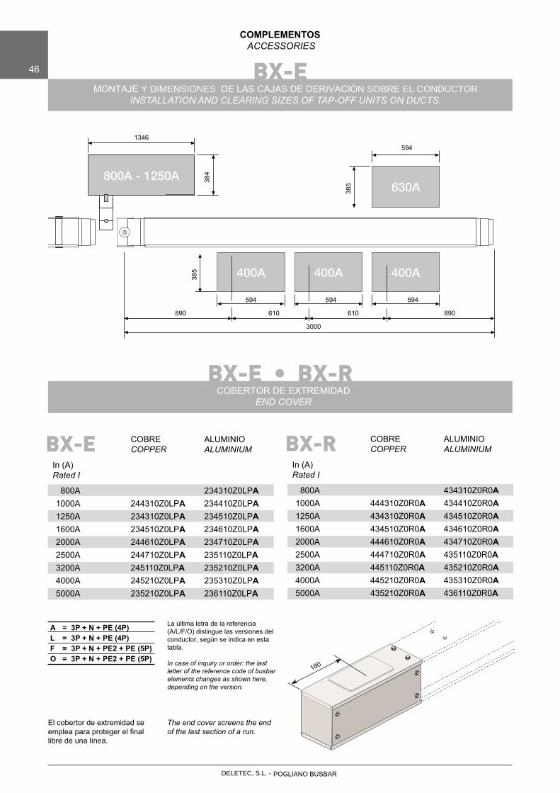
COBERTOR DE EXTREMIDADEND COVER
COBRE ALUMINIO COPPER ALUMINIUM
In (A)Rated I
800A 234310Z0LPA 1000A 244310Z0LPA 234410Z0LPA 1250A 234310Z0LPA 234510Z0LPA 1600A 234510Z0LPA 234610Z0LPA 2000A 244610Z0LPA 234710Z0LPA 2500A 244710Z0LPA 235110Z0LPA 3200A 245110Z0LPA 235210Z0LPA 4000A 245210Z0LPA 235310Z0LPA 5000A 235210Z0LPA 236110Z0LPA
BX-E
La última letra de la referencia (A/L/F/O) distingue las versiones del conductor, según se indica en esta tabla.
In case of inquiry or order: the last letter of the reference code of busbar elements changes as shown here, depending on the version.
A = 3P + N + PE (4P)L = 3P + N + PE (4P)F = 3P + N + PE2 + PE (5P)O = 3P + N + PE2 + PE (5P)
El cobertor de extremidad se emplea para proteger el final libre de una línea.
The end cover screens the end of the last section of a run.
COBRE ALUMINIO COPPER ALUMINIUM
In (A)Rated I
800A 434310Z0R0A 1000A 444310Z0R0A 434410Z0R0A 1250A 434310Z0R0A 434510Z0R0A 1600A 434510Z0R0A 434610Z0R0A 2000A 444610Z0R0A 434710Z0R0A 2500A 444710Z0R0A 435110Z0R0A 3200A 445110Z0R0A 435210Z0R0A 4000A 445210Z0R0A 435310Z0R0A 5000A 435210Z0R0A 436110Z0R0A
BX-R
BX-EMONTAJE Y DIMENSIONES DE LAS CAJAS DE DERIVACIÓN SOBRE EL CONDUCTOR
INSTALLATION AND CLEARING SIZES OF TAP-OFF UNITS ON DUCTS.
1346
594 594 594
594
384
385
385
890 610 610 890
3000
180
POGLIANO BUSBARDELETEC, S.L. -
DELETEC, S.L. - POGLIANO BUSBAR
BX-E • BX-R 47
COMPLEMENTOSACCESSORIES
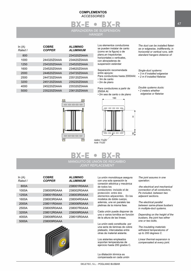
ABRAZADERA DE SUSPENSIÓNHANGER
Los elementos conductoresse pueden instalar de canto(como en la figura) o deplano,en trayectorias horizontales o verticales,con abrazaderas desuspensión estándar
Separación recomendadaentre apoyos:Para conductores hasta 2000A Al:• 3m de canto• 2m de plano
Para conductores a partir de 2500A Al:• 2m sea de canto o de plano
The duct can be installed flatwi- se or edgewise, indifferently, in horizontal or vertical runs, with standard hangers distance of:
Single-duct systems:• 3 m if installed edgewise • 2 m if installed flatwise
Double systems ducts:• 2 meters whether
edgewise or flatwise
In (A) COBRE ALUMINIO Rated I COPPER ALUMINIUM
800 234320Z0AAA 1000 244320Z0AAA 234420Z0AAA 1250 234320Z0AAA 234520Z0AAA 1600 234520Z0AAA 234620Z0AAA 2000 244620Z0AAA 234720Z0AAA 2500 244720Z0AAA 235120Z0AAA 3200 245120Z0AAA 235220Z0AAA 4000 245220Z0AAA 235320Z0AAA 5000 235220Z0AAA 236120Z0AAA
190
H35
ojales 11x20hole 11x20
BX-E • BX-RMANGUITO DE UNIÓN DE RECAMBIO
JOINT REPLACEMENT
La unión monobloque asegura con una sola operación la conexión eléctrica y mecánicade todos losconductores -incluido el de protección- entre dos elementos adyacentes. En los modelos de doble cuerpo, además, une en paralelo las pletinas de la misma fase.
Cada unión puede disponer de uno o varios tornillos en función de la altura de las líneas.
La unión está constituida por una serie de láminas de cobre plateado, intercaladas entre otras de material aislante.
Los aislantes empleados soportan temperaturas de ejercicio hasta 200 grados C.
La dilatación térmica es compensada en cada unión
The joint assures in one operation:
-the electrical and mechanical connection of all conductors, Pe included, between two adjacent sections.
The electrical parallel between same-phase busbars in multiple-duct systems.
Depending on the height of the busbars, the joint has either one or two bolts.
The insulating materials withstand temperatures of up to 200 degrees C.
Linear thermal expansion is compensated at every joint.
In (A) COBRE ALUMINIO Rated I COPPER ALUMINIUM
800A 238001R0AAA 1000A 238000R0AAA 238002R0AAA 1250A 238001R0AAA 238003R0AAA 1600A 238003R0AAA 238004R0AAA 2000A 238011R0AAA 238006R0AAA 2500A 238005R0AAA 238007R0AAA 3200A 238012R0AAA 238009R0AAA 4000A 238008R0AAA 238010R0AAA 5000A 238009R0AAA
48
DELETEC, S.L. - POGLIANO BUSBAR
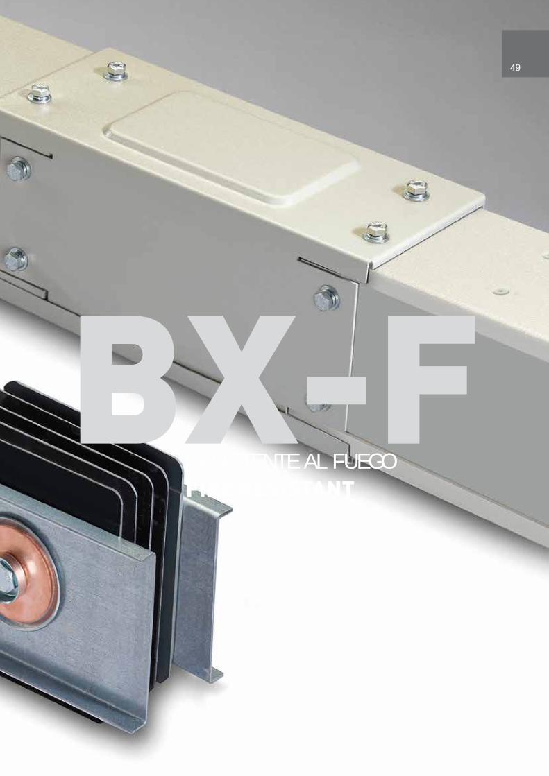
BX-F
49
RESISTENTE AL FUEGOFIRE RESISTANT
BX-F50
ELEMENTOS CONDUCTORESBUSBAR TRUNKING SECTIONS
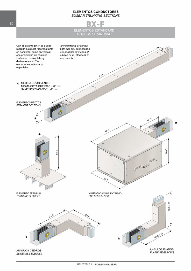
ELEMENTOS ESTÁNDARDSTRAIGHT STANDARD
Con el sistema BX-F se puederealizar cualquier recorrido tanto en horizontal como en vertical, con posibilidad de cambios verticales, horizontales y derivaciones en T en ejecuciones estándar y especiales.
BX-E
N 1 2 3
N 1 2 3
ELEMENTOS RECTOSSTRAIGHT SECTIONS
BX-E BX-E
BX-E + 30
BX
-E +
30
ANGULOS DIEDROSEDGEWISE ELBOWS
ANGULOS PLANOSFLATWISE ELBOWS
Any horizontal or vertical path and any path change are possible by means of elbows or Ts, standard or non standard
*
MEDIDA ENVOLVENTE:MISMA COTA QUE BX-E + 60 mmSAME SIZES AS BX-E + 60 mm
*
*
*
*
ELEMENTO TERMINALTERMINAL ELEMENT
ALIMENTACIÓN DE EXTREMOEND FEED-IN BOX
BX-E
BX-E
BX
-E
BX-E
BX
-E
*
POGLIANO BUSBARDELETEC, S.L. -
DELETEC, S.L. - POGLIANO BUSBAR
BX-F 51
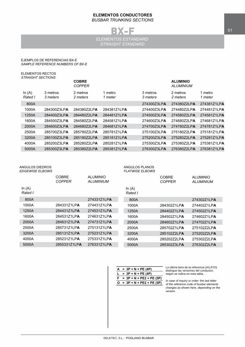
ELEMENTOS CONDUCTORESBUSBAR TRUNKING SECTIONS
ELEMENTOS ESTÁNDARDSTRAIGHT STANDARD
COBRE ALUMINIO COPPER ALUMINIUM
In (A) 3 metros 2 metros 1 metro 3 metros 2 metros 1 metro Rated I 3 meters 2 meters 1 meter 3 meters 2 meters 1 meter
800A 274300Z3LPA 274380Z2LPA 274381Z1LPA 1000A 284300Z3LPA 284380Z2LPA 284381Z1LPA 274400Z3LPA 274480Z2LPA 274481Z1LPA 1250A 284400Z3LPA 284480Z2LPA 284481Z1LPA 274500Z3LPA 274580Z2LPA 274581Z1LPA 1600A 284500Z3LPA 284580Z2LPA 284581Z1LPA 274600Z3LPA 274680Z2LPA 274681Z1LPA 2000A 284600Z3LPA 284680Z2LPA 284681Z1LPA 274700Z3LPA 274780Z2LPA 274781Z1LPA 2500A 285700Z3LPA 285780Z2LPA 285781Z1LPA 275100Z3LPA 275180Z2LPA 275181Z1LPA 3200A 285100Z3LPA 285180Z2LPA 285181Z1LPA 275200Z3LPA 275280Z2LPA 275281Z1LPA 4000A 285200Z3LPA 285280Z2LPA 285281Z1LPA 275300Z3LPA 275380Z2LPA 275381Z1LPA 5000A 285300Z3LPA 285380Z2LPA 285381Z1LPA 276300Z3LPA 276380Z2LPA 276381Z1LPA
A = 3P + N + PE (4P)L = 3P + N + PE (4P)F = 3P + N + PE2 + PE (5P)O = 3P + N + PE2 + PE (5P)
La última letra de la referencia (A/L/F/O) distingue las versiones del conductor, según se indica en esta tabla.
In case of inquiry or order: the last letterof the reference code of busbar elements changes as shown here, depending on the version.
COBRE ALUMINIO COPPER ALUMINIUM
In (A)Rated I
800A 274331Z1LPA 1000A 284331Z1LPA 274431Z1LPA 1250A 284431Z1LPA 274531Z1LPA 1600A 284531Z1LPA 274631Z1LPA 2000A 284631Z1LPA 274731Z1LPA 2500A 285731Z1LPA 275131Z1LPA 3200A 285131Z1LPA 275231Z1LPA 4000A 285231Z1LPA 275331Z1LPA 5000A 2855331Z1LPA 276331Z1LPA
COBRE ALUMINIO COPPER ALUMINIUM
In (A)Rated I
800A 274302Z1LPA 1000A 284302Z1LPA 274402Z1LPA 1250A 284402Z1LPA 274502Z1LPA 1600A 284502Z1LPA 274602Z1LPA 2000A 284602Z1LPA 274702Z1LPA 2500A 285702Z1LPA 275102Z2LPA 3200A 285102Z2LPA 275202Z2LPA 4000A 285202Z2LPA 275302Z2LPA 5000A 285302Z3LPA 276302Z2LPA
ELEMENTOS RECTOSSTRAIGHT SECTIONS
ANGULOS DIEDROSEDGEWISE ELBOWS
ANGULOS PLANOSFLATWISE ELBOWS
EJEMPLOS DE REFERENCIAS BX-ESAMPLE REFERENCE NUMBERS OF BX-E

BX-F52
ELEMENTOS CONDUCTORESBUSBAR TRUNKING SECTIONS
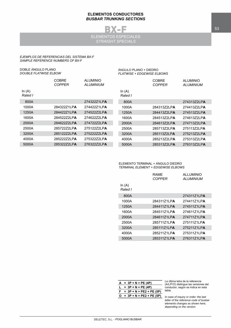
ELEMENTOS ESPECIALESSTRAIGHT SPECIALS
DOBLE ÁNGULO PLANODOUBLE FLATWISE ELBOW
ELEMENTO TERMINAL + ÁNGULO DIEDROTERMINAL ELEMENT + EDGEWISE ELBOWS
Con el sistema BX-F se puede realizar cualquier recorrido tanto en horizontal como en vertical, con posibilidad de cambios verticales, horizontales y derivaciones en T en ejecuciones estándar y especiales.
Any horizontal or vertical path and any path change are flessible by means of elbows or T, standard or non standard
BX-E + 30
BX-E + 30
BX
-E +
60
ÁNGULO PLANO + DIEDROFLATWISE + EDGEWISE ELBOWS
BX-E
BX-E + 30
BX
-E +
30
BX
-E
300
200
100100
100
32
1N
BX-E
*
MEDIDA ENVOLVENTE:MISMAS COTA QUE
BX-E + 60mmSAME SIZES AS
BX-E + 60mm
*
POGLIANO BUSBARDELETEC, S.L. -
BX-F 53
ELEMENTOS CONDUCTORESBUSBAR TRUNKING SECTIONS
ELEMENTOS ESPECIALESSTRAIGHT SPECIALS
A = 3P + N + PE (4P)L = 3P + N + PE (4P)F = 3P + N + PE2 + PE (5P)O = 3P + N + PE2 + PE (5P)
La última letra de la referencia (A/L/F/O) distingue las versiones del conductor, según se indica en esta tabla.
In case of inquiry or order: the last letter of the reference code of busbar elements changes as shown here, depending on the version.
DOBLE ÁNGULO PLANODOUBLE FLATWISE ELBOW
ÁNGULO PLANO + DIEDROFLATWISE + EDGEWISE ELBOWS
ELEMENTO TERMINAL + ÁNGULO DIEDROTERMINAL ELEMENT + EDGEWISE ELBOWS
EJEMPLOS DE REFERENCIAS DEL SISTEMA BX-F SAMPLE REFERENCE NUMBERS OF BX-F
COBRE ALUMINIO COPPER ALUMINIUM
In (A)Rated I
800A 274322Z1LPA 1000A 284322Z1LPA 274422Z1LPA 1250A 284422Z1LPA 274522Z2LPA 1600A 284522Z2LPA 274622Z2LPA 2000A 284622Z2LPA 274722Z2LPA 2500A 285722Z2LPA 275122Z2LPA 3200A 285122Z2LPA 275222Z2LPA 4000A 285222Z2LPA 275322Z2LPA 5000A 285322Z2LPA 276322Z2LPA
COBRE ALUMINIO COPPER ALUMINIUM
In (A)Rated I
800A 274313Z2LPA 1000A 284313Z2LPA 274413Z2LPA 1250A 284413Z2LPA 274513Z2LPA 1600A 284513Z2LPA 274613Z2LPA 2000A 284613Z2LPA 274713Z2LPA 2500A 285713Z2LPA 275113Z2LPA 3200A 285113Z2LPA 275213Z2LPA 4000A 285213Z2LPA 275313Z2LPA 5000A 285313Z2LPA 276313Z2LPA
RAME ALLUMINIO COPPER ALUMINIUM
In (A)Rated I
800A 274311Z1LPA 1000A 284311Z1LPA 274411Z1LPA 1250A 284411Z1LPA 274511Z1LPA 1600A 284511Z1LPA 274611Z1LPA 2000A 284611Z1LPA 274711Z1LPA 2500A 285711Z1LPA 275111Z1LPA 3200A 285111Z1LPA 275211Z1LPA 4000A 285211Z1LPA 275311Z1LPA 5000A 285311Z1LPA 276311Z1LPA
POGLIANO BUSBARDELETEC, S.L. -
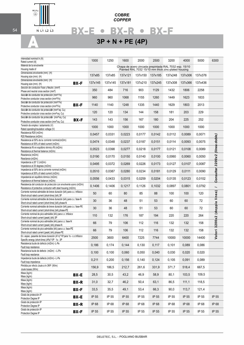
BX-E • BX-R • BX-F54
COBRECOPPER
A
Intensidad nominal In (A)Rated current (A]Material de la envolventeHousing made ofDimensiones envolvente (mm) (H)Housing size (mm) (H)Dimensiones envolvente (mm) (H)Housing size (mm) (H)Sección de conductor Fase y Neutro (mm2)Phase and neutral cross section (mm2)Sección de conductor de protección (mm2 Fe)Protective conductor cross section (mm2 Fe)Sección de conductor de protección (mm2 Fe)Protective conductor cross section (mm2 Fe)Sección de conductor de protección (mm2 eq. Cu)Protective conductor cross section (mm2 eq. Cu)Sección de conductor de protección (mm2 eq. Cu)
2
Protective conductor cross section (mm eq. Cu)Tensión de empleo / aislamiento (V)Rated operating/insulation voltage (V)Resistencia R20 (mΩ/m)R20 Resistance (mΩ/m)Resistencia al 50% de la (mΩ/m)Resistance at 50% of rated current (mΩ/m)Resistencia Rt en equilibrio térmico Rt (mΩ/m)Resistance at thermal balance (mΩ/m)Reactancia (mΩ/m)Reactance (mΩ/m)Impedancia a 20° C (mΩ/m)Impedance at 20 degrees (mΩ/m)Impedancia al 50% de la corriente nominal (mΩ/m)Impedance at 50% of rated current (mΩ/m)Impedancia en equilibrio térmico (mΩ/m)Impedance at thermal balance (mΩ/m)Resistencia del conductor de protección con envolvente acero (mΩ/m)Resistance of protective conductor with steel housing (mΩ/m)Corriente nominal admisible de breve duración (kA) para c.c. trifásicoShort-circuit rated current (short-time) (kA) 3PCorriente nominal admisible de breve duración (kA) para c.c. fase-N Short-circuit rated current (short-time) (kA) phase-NCorriente nominal admisible de breve duración (kA) para c.c. fase-PE Short-circuit rated current (short-time) (kA) phase-PECorriente nominal de pico admisible (kA) para c.c. trifásicoShort-circuit rated current (peak) (kA) 3PCorriente nominal de pico admisible (kA) para c.c. fase-NShort-circuit rated current (peak) (kA) phase-NCorriente nominal de pico admisible (kA) para c.c. fase-PEShort-circuit rated current (peak) (kA) phase-PEEn. espec. pasante de breve duración (A2 para 1s - c.c.trifásicoSpecific energy (short-time) (A2s)*106 1s - 3PResistencia bucle de defecto (mΩ/m) -L-PeFault loop resistanceReactancia bucle de defecto (mΩ/m) - L-PeFault loop reactanceImpedancia bucle de defecto (mΩ/m) - L-PeFault loop impedancePérdida por efecto Joule a In 3RI2 (W/m)Joule losses (W/m)Masa (kg/m)Mass (kg/m)Masa (kg/m)Mass (kg/m)Masa (kg/m)
Mass (kg/m)Grado de protección IP Protection Degree IPGrado de protección IP
Protection Degree IPGrado de protección IP Protection Degree IP
1000 1250 1600 2000 2500 3200 4000 5000 6300
137x85 137x85 137x121 137x150 137x185 137x248 137x306 137x376
137x145 137x145 137x181 137x210 137x245 137x308 137x366 137x436
350 484 716 903 1129 1432 1806 2258
960 960 1068 1155 1260 1449 1623 1833
1140 1140 1248 1335 1440 1629 1803 2013
120 120 134 144 158 181 203 229
143 143 156 167 180 204 225 252
1000 1000 1000 1000 1000 1000 1000 1000
0,0457 0,0331 0,0223 0,0177 0,0142 0,0112 0,0089 0,0071
0,0474 0,0348 0,0237 0,0187 0,0151 0,0114 0,0093 0,0075
0,0523 0,0398 0,0277 0,0218 0,0177 0,0121 0,0108 0,0089
0,0190 0,0170 0,0150 0,0140 0,0100 0,0060 0,0060 0,0050
0,0495 0,0372 0,0269 0,0226 0,0173 0,0127 0,0107 0,0087
0,0387 0,0280 0,0234 0,0181 0,0129 0,0111 0,0090
0,0556 0,0433 0,0315 0,0259 0,0204 0,0135 0,0123 0,0102
0,1406 0,1406 0,1217 0,1126 0,1032 0,0897 0,0801 0,0792
50 60 80 85 88 100 100 120
30 36 48 51 53 60 60 72
30 36 48 51 53 60 60 72
110 132 176 187 194 220 220 264
66 79 106 112 116 132 132 158
66 79 106 112 116 132 132 158
2500 3600 6400 7225 7744 10000 10000 14400 0,186 0,174 0,144 0,130 0,117 0,101 0,089 0,086
0,100 0,100 0,060 0,050 0,040 0,030 0,020 0,020
0,211 0,200 0,156 0,140 0,124 0,105 0,091 0,089
156,9 186,5 212,7 261,6 331,9 371,7 518,4 667,5
28,5 30,5 43,2 46,9 58,9 80,1 103,5
31,0 32,7 46,2 50,4 63,1 86,5 111,1 118,5
33,5 35,5 49,1 53,4 66,3 90,0 113,7 121,4
IP 55 IP 55 IP 55 IP 55 IP 55 IP 55 IP 55 IP 55 IP 55
IP 68 IP 68 IP 68 IP 68 IP 68 IP 68 IP 68 IP 68 IP 68
IP 55 IP 55 IP 55 IP 55 IP 55 IP 55 IP 55 IP 55 IP 55
BX-E
BX-R
BX-F
BX-F
BX-F
BX-E
BX-R
BX-F
3P + N + PE (4P)
Chapa de acero zincada prepintada RAL 7032 esp. 15/10 Painted RAL 7032 15/10 mm thick zinc-plated housing
Valo
ri 3
200x
2 (d
oppi
a lin
ea)
/
Con
sulta
r 32
00x2
(lín
ea d
oble
)
0,0510
POGLIANO BUSBARDELETEC, S.L. -
2
2
ó 2
2
ó 2
2
ó ó 2
2
ó ó 2
2
corriente nominal
s)*106
2 6
-
-
2
109,5
BX-F
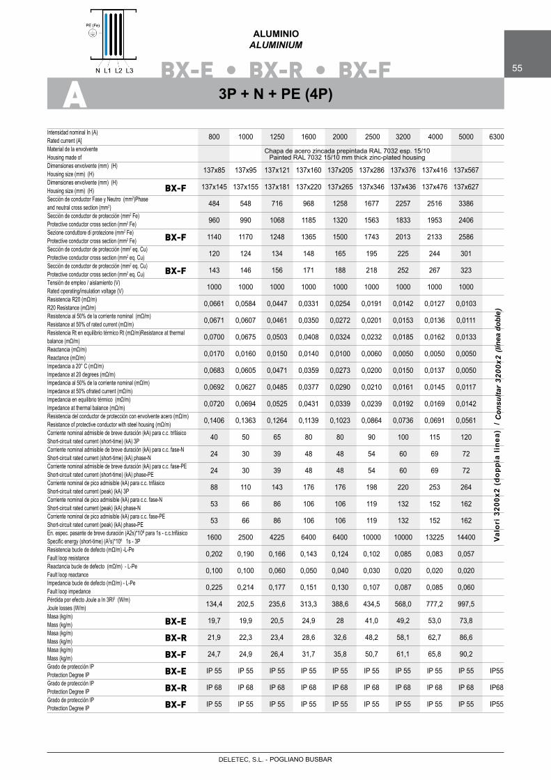
BX-E • BX-R • BX-F 55
ALUMINIOALUMINIUM
AIntensidad nominal In (A)Rated current (A]Material de la envolventeHousing made ofDimensiones envolvente (mm) (H)Housing size (mm) (H)Dimensiones envolvente (mm) (H)Housing size (mm) (H)Sección de conductor Fase y Neutro (mm2)Phase and neutral cross section (mm2)Sección de conductor de protección (mm2 Fe)Protective conductor cross section (mm2 Fe)Sezione conduttore di protezione (mm2 Fe)
2Protective conductor cross section (mm Fe)Sección de conductor de protección (mm2 eq. Cu)Protective conductor cross section (mm2 eq. Cu)Sección de conductor de protección (mm2 eq. Cu)
2
Protective conductor cross section (mm eq. Cu)Tensión de empleo / aislamiento (V)Rated operating/insulation voltage (V)Resistencia R20 (mΩ/m)R20 Resistance (mΩ/m)Resistencia al 50% de la corriente nominal (mΩ/m)Resistance at 50% of rated current (mΩ/m)Resistencia Rt en equilibrio térmico Rt (mΩ/m)Resistance at thermalbalance (mΩ/m)Reactancia (mΩ/m)Reactance (mΩ/m)Impedancia a 20° C (mΩ/m)Impedance at 20 degrees (mΩ/m)Impedancia al 50% de la corriente nominal (mΩ/m)Impedance at 50% ofrated current (mΩ/m)Impedancia en equilibrio térmico (mΩ/m)Impedance at thermal balance (mΩ/m)Resistencia del conductor de protección con envolvente acero (mΩ/m)Resistance of protective conductor with steel housing (mΩ/m)Corriente nominal admisible de breve duración (kA) para c.c. trifásico Short-circuit rated current (short-time) (kA) 3PCorriente nominal admisible de breve duración (kA) para c.c. fase-N Short-circuit rated current (short-time) (kA) phase-NCorriente nominal admisible de breve duración (kA) para c.c. fase-PE Short-circuit rated current (short-time) (kA) phase-PECorriente nominal de pico admisible (kA) para c.c. trifásicoShort-circuit rated current (peak) (kA) 3PCorriente nominal de pico admisible (kA) para c.c. fase-NShort-circuit rated current (peak) (kA) phase-NCorriente nominal de pico admisible (kA) para c.c. fase-PEShort-circuit rated current (peak) (kA) phase-PEEn. espec. pasante de breve duración (A2s)*106 para 1s - c.c.trifásicoSpecific energy (short-time) (A2s)*106 1s - 3PResistencia bucle de defecto (mΩ/m) -L-PeFault loop resistanceReactancia bucle de defecto (mΩ/m) - L-PeFault loop reactanceImpedancia bucle de defecto (mΩ/m) - L-PeFault loop impedancePérdida por efecto Joule a In 3RI2 (W/m)Joule losses (W/m)Masa (kg/m)Mass (kg/m)Masa (kg/m)Mass (kg/m)Masa (kg/m)
Mass (kg/m)Grado de protección IP Protection Degree IP Grado de protección IP Protection Degree IPGrado de protección IP Protection Degree IP
800 1000 1250 1600 2000 2500 3200 4000 5000 6300
137x85 137x95 137x121 137x160 137x205 137x286 137x376 137x416 137x567
137x145 137x155 137x181 137x220 137x265 137x346 137x436 137x476 137x627
484 548 716 968 1258 1677 2257 2516 3386
960 990 1068 1185 1320 1563 1833 1953 2406
1140 1170 1248 1365 1500 1743 2013 2133 2586
120 124 134 148 165 195 225 244 301
143 146 156 171 188 218 252 267 323
1000 1000 1000 1000 1000 1000 1000 1000 1000
0,0661 0,0584 0,0447 0,0331 0,0254 0,0191 0,0142 0,0127 0,0103
0,0671 0,0607 0,0461 0,0350 0,0272 0,0201 0,0153 0,0136 0,0111
0,0700 0,0675 0,0503 0,0408 0,0324 0,0232 0,0185 0,0162 0,0133
0,0170 0,0160 0,0150 0,0140 0,0100 0,0060 0,0050 0,0050 0,0050
0,0683 0,0605 0,0471 0,0359 0,0273 0,0200 0,0150 0,0137 0,0050
0,0692 0,0627 0,0485 0,0377 0,0290 0,0210 0,0161 0,0145 0,0117
0,0720 0,0694 0,0525 0,0431 0,0339 0,0239 0,0192 0,0169 0,0142 0,1406 0,1363 0,1264 0,1139 0,1023 0,0864 0,0736 0,0691 0,0561
40 50 65 80 80 90 100 115 120
24 30 39 48 48 54 60 69 72
24 30 39 48 48 54 60 69 72
88 110 143 176 176 198 220 253 264
53 66 86 106 106 119 132 152 162
53 66 86 106 106 119 132 152 162
1600 2500 4225 6400 6400 10000 10000 13225 14400
0,202 0,190 0,166 0,143 0,124 0,102 0,085 0,083 0,057
0,100 0,100 0,060 0,050 0,040 0,030 0,020 0,020 0,020 0,225 0,214 0,177 0,151 0,130 0,107 0,087 0,085 0,060
134,4 202,5 235,6 313,3 388,6 434,5 568,0 777,2 997,5
19,7 19,9 20,5 24,9 28 41,0 49,2 53,0 73,8
21,9 22,3 23,4 28,6 32,6 48,2 58,1 62,7 86,6
24,7 24,9 26,4 31,7 35,8 50,7 61,1 65,8 90,2
IP 55 IP 55 IP 55 IP 55 IP 55 IP 55 IP 55 IP 55 IP 55 IP55
IP 68 IP 68 IP 68 IP 68 IP 68 IP 68 IP 68 IP 68 IP 68 IP68
IP 55 IP 55 IP 55 IP 55 IP 55 IP 55 IP 55 IP 55 IP 55 IP55
BX-E
BX-R
BX-F
BX-F
BX-F
BX-E
BX-R
BX-F
3P + N + PE (4P)
Chapa de acero zincada prepintada RAL 7032 esp. 15/10 Painted RAL 7032 15/10 mm thick zinc-plated housing
Valo
ri 3
200x
2 (d
oppi
a lin
ea)
/
BX-F
POGLIANO BUSBARDELETEC, S.L. -
Con
sulta
r 32
00x2
(lín
ea d
oble
)

BX-E • BX-R56
COBRECOPPER
L
Intensidad nominal In (A)Rated current (A]Material de la envolventeHousing made ofDimensiones envolvente (mm) (H)Housing size (mm) (H)Sección de conductor Fase y Neutro (mm2)Phase and neutral cross section (mm2)Sección de conductor de protección (mm2 Al)Protective conductor cross section (mm2 Al)Sección de conductor de protección (mm2 eq. Cu)Protective conductor cross section (mm2 eq. Cu)Tensión de empleo / aislamiento (V)Rated operating/insulation voltage (V)Resistencia R20 (mΩ/m)R20 Resistance (mΩ/m)Resistencia al 50% de la corriente nominal (mΩ/m)Resistance at 50% of rated current (mΩ/m)Resistencia Rt en equilibrio térmico (mΩ/m)Resistance at thermal balance (mΩ/m)Reactancia (mΩ/m)Reactance (mΩ/m)Impedancia a 20° C (mΩ/m)Impedance at 20 degrees (mΩ/m)Impedancia al 50% de la corriente nominal (mΩ/m)Impedance at 50% of rated current (mΩ/m)Impedancia en equilibrio térmico (mΩ/m)Impedance at thermal balance (mΩ/m)Resistencia del conductor de protección (mΩ/m)Resistance of protective conductor (mΩ/m)Corriente nominal admisible de breve duración (kA) para c.c. trifásico Short-circuit rated current (short-time) (kA) 3PCorriente nominal admisible de breve duración (kA) para c.c. fase-N Short-circuit rated current (short-time) (kA) phase-NCorriente nominal admisible de breve duración (kA) para c.c. fase-PE Short-circuit rated current (short-time) (kA) phase-PECorriente nominal de pico admisible (kA) para c.c. trifásicoShort-circuit rated current (peak) (kA) 3PCorriente nominal de pico admisible (kA) para c.c. fase-NShort-circuit rated current (peak) (kA) phase-NCorriente nominal admisible de breve duración (kA) para c.c. fase-PE Short-circuit rated current (peak) (kA) phase-PEEn. espec. pasante de breve duración (A2s)*106 para 1s - c.c.trifásicoSpecific energy (short-time) (A2s)*106 1s - 3PResistencia bucle de defecto (mΩ/m) -L-PeFault loop resistanceReactancia bucle de defecto (mΩ/m) - L-PeFault loop reactanceImpedancia bucle de defecto (mΩ/m) - L-PeFault loop impedancePérdida por efecto Joule a In 3RI2 (W/m)Joule losses (W/m)Masa (kg/m)
Mass (kg/m)Masa (kg/m)Mass (kg/m)Grado de protección IP
Protection Degree IPGrado de protección IP Protection Degree IP
1000 1250 1600 2000 2500 3200 4000 5000 6300
137x85 137x85 137x121 137x150 137x185 137x248 137x306 137x376
350 484 716 903 1129 1432 1806 2258
1600 1600 1780 1925 2100 2415 2705 2735 889 889 989 1069 1167 1342 1503 1519
1000 1000 1000 1000 1000 1000 1000 1000
0,0457 0,0331 0,0223 0,0177 0,0142 0,0112 0,0089 0,0071
0,0474 0,0348 0,0237 0,0187 0,0151 0,0114 0,0093 0,0075
0,0523 0,0398 0,0277 0,0218 0,0177 0,0121 0,0108 0,0089
0,0190 0,0170 0,0150 0,0140 0,0100 0,0060 0,0060 0,0050
0,0495 0,0372 0,0269 0,0226 0,0173 0,0127 0,0107 0,0087
0,0510 0,0387 0,0280 0,0234 0,0181 0,0129 0,0111 0,0090
0,0556 0,0433 0,0315 0,0259 0,0204 0,0135 0,0123 0,0102
0,020 0,020 0,018 0,0166 0,0152 0,0132 0,0118 0,0117
50 60 80 85 88 100 100 120
30 36 48 51 53 60 60 72
30 36 48 51 53 60 60 72
110 132 176 187 194 220 220 264
66 79 106 112 116 132 132 158
66 79 106 112 116 132 132 158
2500 3600 6400 7225 7744 10000 10000 14400
0,063 0,051 0,038 0,032 0,028 0,023 0,019 0,017
0,100 0,100 0,060 0,050 0,040 0,030 0,020 0,020
0,104 0,112 0,071 0,059 0,049 0,038 0,028 0,026
156,9 186,5 212,7 261,6 331,9 371,7 518,4 667,5
25,7 27,5 38,9 42,2 53,0 72,1 93,2 98,6
28,2 29,7 41,9 45,7 57,2 77,5 100,8 107,6
IP 55 IP 55 IP 55 IP 55 IP 55 IP 55 IP 55 IP 55 IP 55
IP 68 IP 68 IP 68 IP 68 IP 68 IP 68 IP 68 IP 68 IP 68
BX-E
BX-R
BX-E
BX-R
3P + N + PE (4P)
Aluminio prepintado RAL 7032 esp. 25/10 Painted RAL 7032 25/10 mm thick aluminium housing
Valo
ri 3
200x
2 (d
oppi
a lin
ea)
/
POGLIANO BUSBARDELETEC, S.L. -
Con
sulta
r 32
00x2
(lín
ea d
oble
)
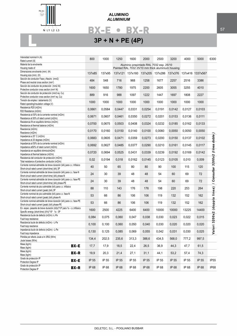
BX-E • BX-R 57
ALUMINIOALUMINIUM
L
Intensidad nominal In (A)Rated current (A]Material de la envolventeHousing made ofDimensiones envolvente (mm) (H)Housing size (mm) (H)Sección de conductor Fase y Neutro (mm2)Phase and neutral cross section (mm2)Sección de conductor de protección (mm2 Al)Protective conductor cross section (mm2 Al)Sección de conductor de protección (mm2 eq. Cu)Protective conductor cross section (mm2 eq. Cu)Tensión de empleo / aislamiento (V)Rated operating/insulation voltage (V)Resistencia R20 (mΩ/m)R20 Resistance (mΩ/m)Resistencia al 50% de la corriente nominal (mΩ/m)Resistance at 50% of rated current (mΩ/m)Resistencia Rt en equilibrio térmico (mΩ/m)Resistance at thermal balance (mΩ/m)Reactancia (mΩ/m)Reactance (mΩ/m)Impedancia a 20° C (mΩ/m)Impedance at 20 degrees (mΩ/m)Impedancia al 50% de la corriente nominal (mΩ/m)Impedance at50% of rated current (mΩ/m)Impedancia en equilibrio térmico(mΩ/m)Impedance at thermal balance (mΩ/m)Resistencia del conductor de protección (mΩ/m)Total resistance of protective conductor (mΩ/m)Corriente nominal admisible de breve duración (kA) para c.c. trifásicoShort-circuit rated current (short-time) (kA) 3PCorriente nominal admisible de breve duración (kA) para c.c. fase-N Short-circuit rated current (short-time) (kA) phase-NCorriente nominal admisible de breve duración (kA) para c.c. fase-PE Short-circuit rated current (short-time) (kA) phase-PECorriente nominal de pico admisible (kA) para c.c. trifásicoShort-circuit rated current (peak) (kA) 3PCorriente nominal de pico admisible (kA) para c.c. fase-NShort-circuit rated current (peak) (kA) phase-NCorriente nominal admisible de breve duración (kA) para c.c. fase-PE Short-circuit rated current (peak) (kA) phase-PEEn. espec. pasante de breve duración (A2s)*106 para 1s - c.c.trifásicoSpecific energy (short-time) (A2s)*106 1s - 3PResistencia bucle de defecto (mΩ/m) -L-PeFault loop resistanceReactancia bucle de defecto (mΩ/m) - L-PeFault loop reactanceImpedancia bucle de defecto (mΩ/m) - L-PeFault loop impedancePérdida por efecto Joule a In 3RI2 (W/m)Joule losses (W/m)Masa (kg/m)
Mass (kg/m)Masa (kg/m)Mass (kg/m)Grado de protección IP Protection Degree IPGrado de protección IP Protection Degree IP
800 1000 1250 1600 2000 2500 3200 4000 5000 6300
137x85 137x95 137x121 137x160 137x205 137x286 137x376 137x416 1337x567
484 548 716 968 1258 1677 2257 2516 3386
1600 1650 1780 1975 2200 2605 3055 3255 4010
889 916 988 1097 1222 1447 1697 1808 2227
1000 1000 1000 1000 1000 1000 1000 1000 1000
0,0661 0,0584 0,0447 0,0331 0,0254 0,0191 0,0142 0,0127 0,0103
0,0671 0,0607 0,0461 0,0350 0,0272 0,0201 0,0153 0,0136 0,0111
0,0700 0,0675 0,0503 0,0408 0,0324 0,0232 0,0185 0,0162 0,0133
0,0170 0,0160 0,0150 0,0140 0,0100 0,0060 0,0050 0,0050 0,0050
0,0683 0,0605 0,0471 0,0359 0,0273 0,0200 0,0150 0,0137 0,0102
0,0692 0,0627 0,0485 0,0377 0,0290 0,0210 0,0161 0,0145 0,0117
0,0720 0,0694 0,0525 0,0431 0,0339 0,0239 0,0192 0,0169 0,0142 0,02 0,0194 0,018 0,0162 0,0145 0,0123 0,0105 0,010 0,009
40 50 65 80 80 90 100 115 120
24 30 39 48 48 54 60 69 72
24 30 39 48 48 54 60 69 72
88 110 143 176 176 198 220 253 264
53 66 86 106 106 119 132 152 162
53 66 86 106 106 119 132 152 162
1600 2500 4225 6400 6400 10000 10000 13225 14400
0,084 0,075 0,060 0,047 0,038 0,030 0,023 0,022 0,015
0,100 0,100 0,060 0,050 0,040 0,030 0,020 0,020 0,020
0,130 0,125 0,085 0,069 0,055 0,042 0,031 0,030 0,025
134,4 202,5 235,6 313,3 388,6 434,5 568,0 777,2 997,5
17,7 17,9 18,5 22,4 26,5 36,9 44,3 47,7 61,5
19,9 20,3 21,4 27,1 31,1 44,1 53,2 57,4 74,3
IP 55 IP 55 IP 55 IP 55 IP 55 IP 55 IP 55 IP 55 IP 55 IP55
IP 68 IP 68 IP 68 IP 68 IP 68 IP 68 IP 68 IP 68 IP 68 IP68
BX-E
BX-R
BX-E
BX-R
3P + N + PE (4P)
Aluminio prepintado RAL 7032 esp. 25/10 Painted RAL 7032 25/10 mm thick aluminium housing
Valo
ri 3
200x
2 (d
oppi
a lin
ea)
/
POGLIANO BUSBARDELETEC, S.L. -
Con
sulta
r 32
00x2
(lín
ea d
oble
)
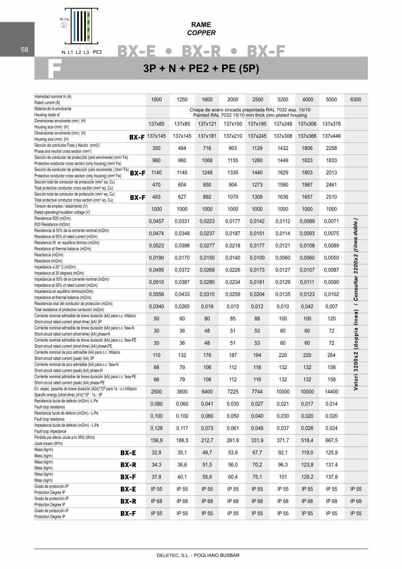
BX-E • BX-R • BX-F58
RAMECOPPER
FIntensidad nominal In (A)Rated current (A]Material de la envolventeHousing made ofDimensiones envolvente (mm) (H)Housing size (mm) (H)Dimensiones envolvente (mm) (H)Housing size (mm) (H)Sección de conductor Fase y Neutro (mm2)Phase and neutral cross section (mm2)Sección de conductor de protección (solo envolvente) (mm2 Fe)Protective conductor cross section (only housing) (mm2 Fe)Sección de conductor de protección (solo envolvente ) (mm2 Fe)
2Protective conductor cross section (only housing) (mm Fe)Sección total de conductor de protección (mm2 eq. Cu)Total protective conductor cross section (mm2 eq. Cu)Sección total de conductor de protección (mm2 eq. Cu)
2
Total protective conductor cross section (mm eq. Cu)Tensión de empleo / aislamiento (V)Rated operating/insulation voltage (V)Resistencia R20 (mΩ/m)R20 Resistance (mΩ/m)Resistencia al 50% de la corriente nominal (mΩ/m)Resistance at 50% of rated current (mΩ/m)Resistencia Rt en equilibrio térmico (mΩ/m)Resistance at thermal balance (mΩ/m)Reactancia (mΩ/m)Reactance (mΩ/m)Impedancia a 20° C (mΩ/m)Impedance at 20 degrees (mΩ/m)Impedancia al 50% de la corriente nominal (mΩ/m)Impedance at 50% of rated current (mΩ/m)Impedancia en equilibrio térmico(mΩ/m)Impedance at thermal balance (mΩ/m)Resistencia total del conductor de protección (mΩ/m)Total resistance of protective conductor (mΩ/m)Corriente nominal admisible de breve duración (kA) para c.c. trifásico Short-circuit rated current (short-time) (kA) 3PCorriente nominal admisible de breve duración (kA) para c.c. fase-NShort-circuit rated current (short-time) (kA) phase-NCorriente nominal admisible de breve duración (kA) para c.c. fase-PE Short-circuit rated current (short-time) (kA) phase-PECorriente nominal de pico admisible (kA) para c.c. trifásicoShort-circuit rated current (peak) (kA) 3PCorriente nominal de pico admisible (kA) para c.c. fase-NShort-circuit rated current (peak) (kA) phase-NCorriente nominal admisible de breve duración (kA) para c.c. fase-PE Short-circuit rated current (peak) (kA) phase-PEEn. espec. pasante de breve duración (A2s)*106 para 1s - c.c.trifásicoSpecific energy (short-time) (A2s)*106 1s - 3PResistencia bucle de defecto (mΩ/m) -L-PeFault loop resistanceReactancia bucle de defecto (mΩ/m) - L-PeFault loop reactanceImpedancia bucle de defecto (mΩ/m) - L-PeFault loop impedancePérdida por efecto Joule a In 3RI2 (W/m)Joule losses (W/m)Masa (kg/m)Mass (kg/m)Masa (kg/m)Mass (kg/m)Masa (kg/m)
Mass (kg/m)Grado de protección IP Protection Degree IP Grado de protección IPProtection Degree IP Grado de protección IP Protection Degree IP
1000 1250 1600 2000 2500 3200 4000 5000 6300
137x85 137x85 137x121 137x150 137x185 137x248 137x306 137x376
137x145 137x145 137x181 137x210 137x245 137x308 137x366 137x446 350 484 716 903 1129 1432 1806 2258
960 960 1068 1155 1260 1449 1623 1833
1140 1140 1248 1335 1440 1629 1803 2013
470 604 850 904 1273 1590 1987 2461
493 627 892 1070 1309 1636 1657 2510
1000 1000 1000 1000 1000 1000 1000 1000
0,0457 0,0331 0,0223 0,0177 0,0142 0,0112 0,0089 0,0071
0,0474 0,0348 0,0237 0,0187 0,0151 0,0114 0,0093 0,0075
0,0523 0,0398 0,0277 0,0218 0,0177 0,0121 0,0108 0,0089
0,0190 0,0170 0,0150 0,0140 0,0100 0,0060 0,0060 0,0050
0,0495 0,0372 0,0269 0,0226 0,0173 0,0127 0,0107 0,0087
0,0510 0,0387 0,0280 0,0234 0,0181 0,0129 0,0111 0,0090
0,0556 0,0433 0,0315 0,0259 0,0204 0,0135 0,0123 0,0102
0,0340 0,0265 0,019 0,015 0,012 0,010 0,042 0,007
50 60 80 85 88 100 100 120
30 36 48 51 53 60 60 72
30 36 48 51 53 60 60 72
110 132 176 187 194 220 220 264
66 79 106 112 116 132 132 158
66 79 106 112 116 132 132 158
2500 3600 6400 7225 7744 10000 10000 14400
0,080 0,060 0,041 0,035 0,027 0,021 0,017 0,014
0,100 0,100 0,060 0,050 0,040 0,030 0,020 0,020
0,128 0,117 0,073 0,061 0,048 0,037 0,026 0,024
156,9 186,5 212,7 261,6 331,9 371,7 518,4 667,5
32,8 35,1 49,7 53,9 67,7 92,1 119,0 125,9
34,3 36,6 51,5 56,0 70,2 96,3 123,8 131,4
37,8 40,1 55,6 60,4 75,1 101 129,2 137,8
IP 55 IP 55 IP 55 IP 55 IP 55 IP 55 IP 55 IP 55 IP 55
IP 68 IP 68 IP 68 IP 68 IP 68 IP 68 IP 68 IP 68 IP 68
IP 55 IP 55 IP 55 IP 55 IP 55 IP 55 IP 55 IP 55 IP 55
BX-E
BX-R
BX-F
BX-F
BX-F
BX-E
BX-R
BX-F
3P + N + PE2 + PE (5P)
Chapa de acero zincada prepintada RAL 7032 esp. 15/10 Painted RAL 7032 15/10 mm thick zinc-plated housing
BX-F
Valo
ri 3
200x
2 (d
oppi
a lin
ea)
/
POGLIANO BUSBARDELETEC, S.L. -
Con
sulta
r 32
00x2
(lín
ea d
oble
)
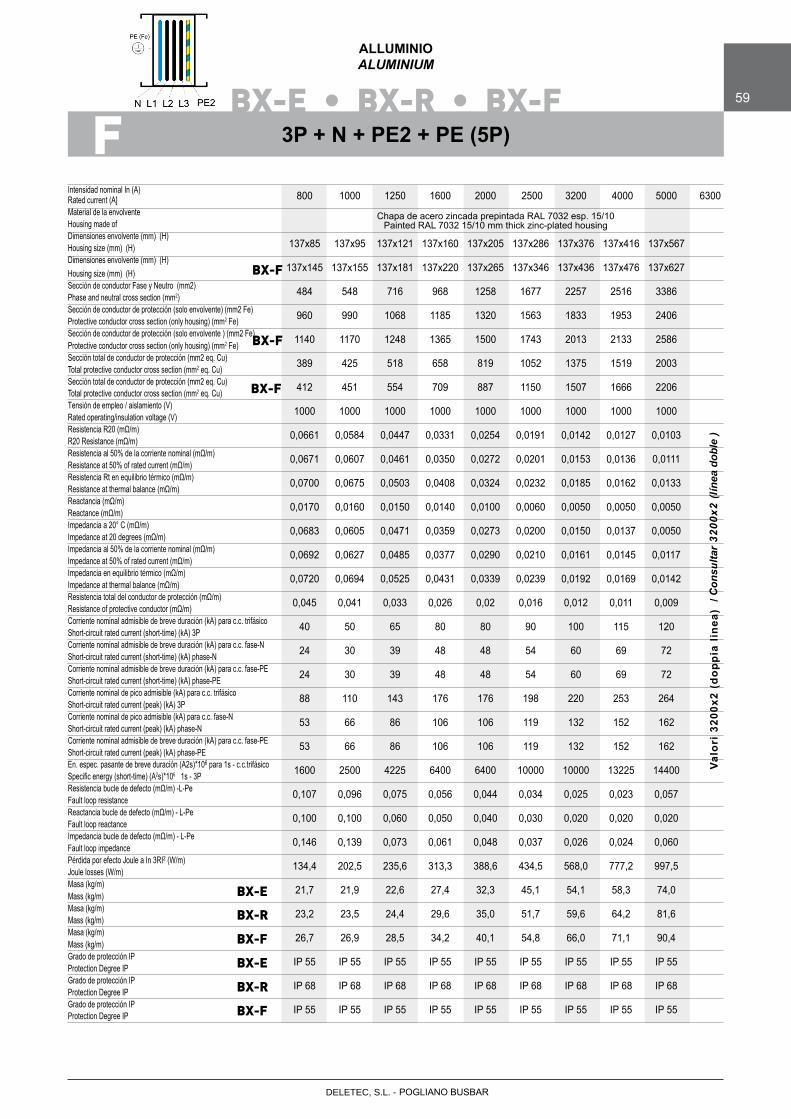
BX-E • BX-R • BX-F 59
ALLUMINIOALUMINIUM
FIntensidad nominal In (A)Rated current (A]Material de la envolventeHousing made ofDimensiones envolvente (mm) (H)Housing size (mm) (H)Dimensiones envolvente (mm) (H)Housing size (mm) (H)Sección de conductor Fase y Neutro (mm2)Phase and neutral cross section (mm2)Sección de conductor de protección (solo envolvente) (mm2 Fe)Protective conductor cross section (only housing) (mm2 Fe)Sección de conductor de protección (solo envolvente ) (mm2 Fe)
2Protective conductor cross section (only housing) (mm Fe)Sección total de conductor de protección (mm2 eq. Cu)Total protective conductor cross section (mm2 eq. Cu)Sección total de conductor de protección (mm2 eq. Cu)
2
Total protective conductor cross section (mm eq. Cu)Tensión de empleo / aislamiento (V)Rated operating/insulation voltage (V)Resistencia R20 (mΩ/m)R20 Resistance (mΩ/m)Resistencia al 50% de la corriente nominal (mΩ/m)Resistance at 50% of rated current (mΩ/m)Resistencia Rt en equilibrio térmico (mΩ/m)Resistance at thermal balance (mΩ/m)Reactancia (mΩ/m)Reactance (mΩ/m)Impedancia a 20° C (mΩ/m)Impedance at 20 degrees (mΩ/m)Impedancia al 50% de la corriente nominal (mΩ/m)Impedance at 50% of rated current (mΩ/m)Impedancia en equilibrio térmico (mΩ/m)Impedance at thermal balance (mΩ/m)Resistencia total del conductor de protección (mΩ/m)Resistance of protective conductor (mΩ/m)Corriente nominal admisible de breve duración (kA) para c.c. trifásico Short-circuit rated current (short-time) (kA) 3PCorriente nominal admisible de breve duración (kA) para c.c. fase-N Short-circuit rated current (short-time) (kA) phase-NCorriente nominal admisible de breve duración (kA) para c.c. fase-PE Short-circuit rated current (short-time) (kA) phase-PECorriente nominal de pico admisible (kA) para c.c. trifásicoShort-circuit rated current (peak) (kA) 3PCorriente nominal de pico admisible (kA) para c.c. fase-NShort-circuit rated current (peak) (kA) phase-NCorriente nominal admisible de breve duración (kA) para c.c. fase-PE Short-circuit rated current (peak) (kA) phase-PEEn. espec. pasante de breve duración (A2s)*106 para 1s - c.c.trifásicoSpecific energy (short-time) (A2s)*106 1s - 3PResistencia bucle de defecto (mΩ/m) -L-PeFault loop resistanceReactancia bucle de defecto (mΩ/m) - L-PeFault loop reactanceImpedancia bucle de defecto (mΩ/m) - L-PeFault loop impedancePérdida por efecto Joule a In 3RI2 (W/m)Joule losses (W/m)Masa (kg/m)Mass (kg/m)Masa (kg/m)Mass (kg/m)Masa (kg/m)
Mass (kg/m)Grado de protección IP Protection Degree IPGrado de protección IPProtection Degree IPGrado de protección IP Protection Degree IP
800 1000 1250 1600 2000 2500 3200 4000 5000 6300
137x85 137x95 137x121 137x160 137x205 137x286 137x376 137x416 137x567
137x145 137x155 137x181 137x220 137x265 137x346 137x436 137x476 137x627
484 548 716 968 1258 1677 2257 2516 3386
960 990 1068 1185 1320 1563 1833 1953 2406
1140 1170 1248 1365 1500 1743 2013 2133 2586
389 425 518 658 819 1052 1375 1519 2003
412 451 554 709 887 1150 1507 1666 2206
1000 1000 1000 1000 1000 1000 1000 1000 1000
0,0661 0,0584 0,0447 0,0331 0,0254 0,0191 0,0142 0,0127 0,0103
0,0671 0,0607 0,0461 0,0350 0,0272 0,0201 0,0153 0,0136 0,0111
0,0700 0,0675 0,0503 0,0408 0,0324 0,0232 0,0185 0,0162 0,0133
0,0170 0,0160 0,0150 0,0140 0,0100 0,0060 0,0050 0,0050 0,0050
0,0683 0,0605 0,0471 0,0359 0,0273 0,0200 0,0150 0,0137 0,0050
0,0692 0,0627 0,0485 0,0377 0,0290 0,0210 0,0161 0,0145 0,0117
0,0720 0,0694 0,0525 0,0431 0,0339 0,0239 0,0192 0,0169 0,0142 0,045 0,041 0,033 0,026 0,02 0,016 0,012 0,011 0,009
40 50 65 80 80 90 100 115 120
24 30 39 48 48 54 60 69 72 24 30 39 48 48 54 60 69 72
88 110 143 176 176 198 220 253 264
53 66 86 106 106 119 132 152 162
53 66 86 106 106 119 132 152 162
1600 2500 4225 6400 6400 10000 10000 13225 14400
0,107 0,096 0,075 0,056 0,044 0,034 0,025 0,023 0,057
0,100 0,100 0,060 0,050 0,040 0,030 0,020 0,020 0,020
0,146 0,139 0,073 0,061 0,048 0,037 0,026 0,024 0,060
134,4 202,5 235,6 313,3 388,6 434,5 568,0 777,2 997,5
21,7 21,9 22,6 27,4 32,3 45,1 54,1 58,3 74,0
23,2 23,5 24,4 29,6 35,0 51,7 59,6 64,2 81,6
26,7 26,9 28,5 34,2 40,1 54,8 66,0 71,1 90,4
IP 55 IP 55 IP 55 IP 55 IP 55 IP 55 IP 55 IP 55 IP 55
IP 68 IP 68 IP 68 IP 68 IP 68 IP 68 IP 68 IP 68 IP 68
IP 55 IP 55 IP 55 IP 55 IP 55 IP 55 IP 55 IP 55 IP 55
BX-E
BX-R
BX-F
BX-F
BX-F
BX-E
BX-R
BX-F
3P + N + PE2 + PE (5P)
Chapa de acero zincada prepintada RAL 7032 esp. 15/10 Painted RAL 7032 15/10 mm thick zinc-plated housing
Valo
ri 3
200x
2 (d
oppi
a lin
ea)
/
BX-F
POGLIANO BUSBARDELETEC, S.L. -
ínea
dob
le)
Con
sulta
r 32
00x2
(l
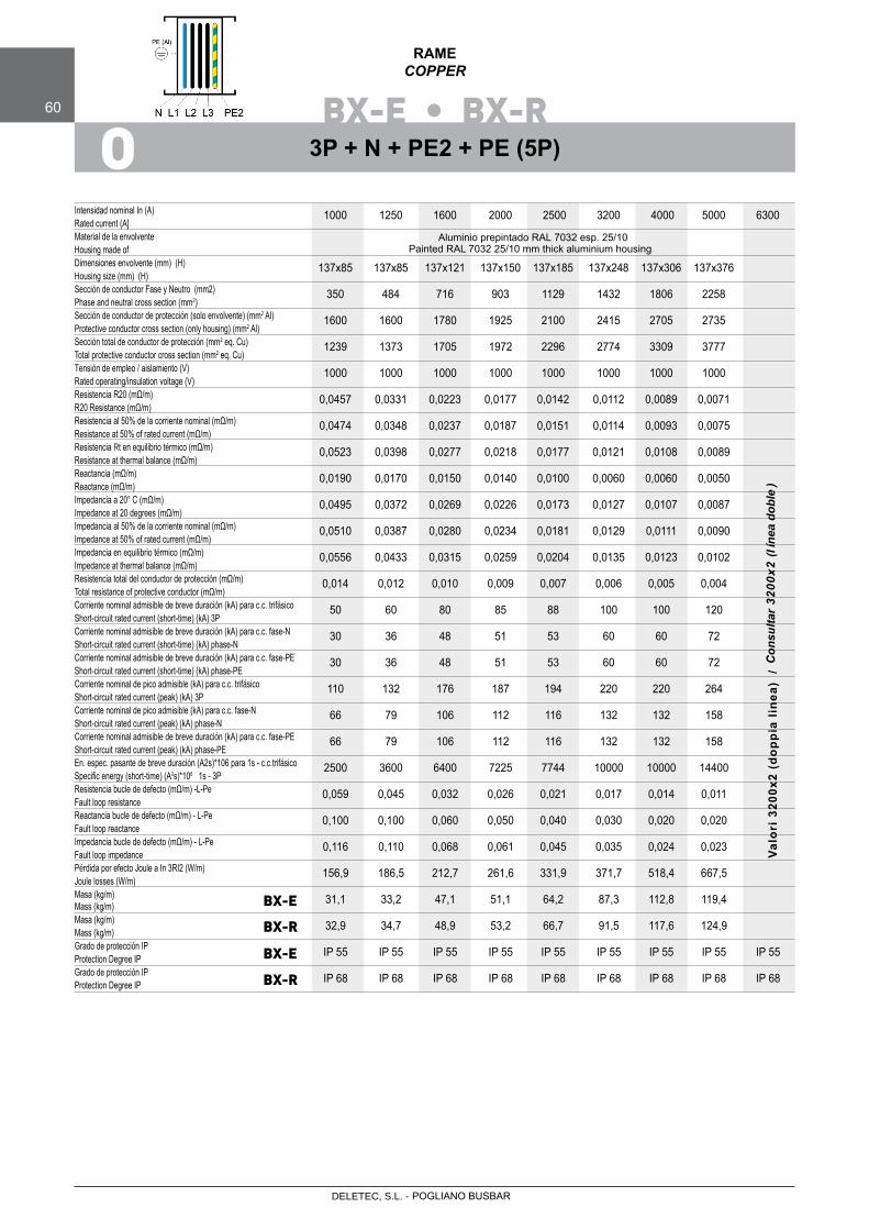
BX-E • BX-R60
RAMECOPPER
O
Intensidad nominal In (A)Rated current (A]Material de la envolventeHousing made ofDimensiones envolvente (mm) (H)Housing size (mm) (H)Sección de conductor Fase y Neutro (mm2)Phase and neutral cross section (mm2)Sección de conductor de protección (solo envolvente) (mm2 Al)Protective conductor cross section (only housing) (mm2 Al)Sección total de conductor de protección (mm2 eq. Cu)Total protective conductor cross section (mm2 eq. Cu)Tensión de empleo / aislamiento (V)Rated operating/insulation voltage (V)Resistencia R20 (mΩ/m)R20 Resistance (mΩ/m)Resistencia al 50% de la corriente nominal (mΩ/m)Resistance at 50% of rated current (mΩ/m)Resistencia Rt en equilibrio térmico (mΩ/m)Resistance at thermal balance (mΩ/m)Reactancia (mΩ/m)Reactance (mΩ/m)Impedancia a 20° C (mΩ/m)Impedance at 20 degrees (mΩ/m)Impedancia al 50% de la corriente nominal (mΩ/m)Impedance at 50% of rated current (mΩ/m)Impedancia en equilibrio térmico (mΩ/m)Impedance at thermal balance (mΩ/m)Resistencia total del conductor de protección (mΩ/m)Total resistance of protective conductor (mΩ/m)Corriente nominal admisible de breve duración (kA) para c.c. trifásico Short-circuit rated current (short-time) (kA) 3PCorriente nominal admisible de breve duración (kA) para c.c. fase-N Short-circuit rated current (short-time) (kA) phase-NCorriente nominal admisible de breve duración (kA) para c.c. fase-PE Short-circuit rated current (short-time) (kA) phase-PECorriente nominal de pico admisible (kA) para c.c. trifásicoShort-circuit rated current (peak) (kA) 3PCorriente nominal de pico admisible (kA) para c.c. fase-NShort-circuit rated current (peak) (kA) phase-NCorriente nominal admisible de breve duración (kA) para c.c. fase-PE Short-circuit rated current (peak) (kA) phase-PEEn. espec. pasante de breve duración (A2s)*106 para 1s - c.c.trifásicoSpecific energy (short-time) (A2s)*106 1s - 3PResistencia bucle de defecto (mΩ/m) -L-PeFault loop resistanceReactancia bucle de defecto (mΩ/m) - L-PeFault loop reactanceImpedancia bucle de defecto (mΩ/m) - L-PeFault loop impedancePérdida por efecto Joule a In 3RI2 (W/m)Joule losses (W/m)Masa (kg/m)
Mass (kg/m)Masa (kg/m)Mass (kg/m)Grado de protección IP Protection Degree IP Grado de protección IP Protection Degree IP
1000 1250 1600 2000 2500 3200 4000 5000 6300
137x85 137x85 137x121 137x150 137x185 137x248 137x306 137x376
350 484 716 903 1129 1432 1806 2258
1600 1600 1780 1925 2100 2415 2705 2735
1239 1373 1705 1972 2296 2774 3309 3777
1000 1000 1000 1000 1000 1000 1000 1000
0,0457 0,0331 0,0223 0,0177 0,0142 0,0112 0,0089 0,0071
0,0474 0,0348 0,0237 0,0187 0,0151 0,0114 0,0093 0,0075
0,0523 0,0398 0,0277 0,0218 0,0177 0,0121 0,0108 0,0089
0,0190 0,0170 0,0150 0,0140 0,0100 0,0060 0,0060 0,0050
0,0495 0,0372 0,0269 0,0226 0,0173 0,0127 0,0107 0,0087
0,0510 0,0387 0,0280 0,0234 0,0181 0,0129 0,0111 0,0090
0,0556 0,0433 0,0315 0,0259 0,0204 0,0135 0,0123 0,0102
0,014 0,012 0,010 0,009 0,007 0,006 0,005 0,004
50 60 80 85 88 100 100 120
30 36 48 51 53 60 60 72
30 36 48 51 53 60 60 72
110 132 176 187 194 220 220 264
66 79 106 112 116 132 132 158
66 79 106 112 116 132 132 158
2500 3600 6400 7225 7744 10000 10000 14400
0,059 0,045 0,032 0,026 0,021 0,017 0,014 0,011
0,100 0,100 0,060 0,050 0,040 0,030 0,020 0,020
0,116 0,110 0,068 0,061 0,045 0,035 0,024 0,023
156,9 186,5 212,7 261,6 331,9 371,7 518,4 667,5
31,1 33,2 47,1 51,1 64,2 87,3 112,8 119,4
32,9 34,7 48,9 53,2 66,7 91,5 117,6 124,9
IP 55 IP 55 IP 55 IP 55 IP 55 IP 55 IP 55 IP 55 IP 55
IP 68 IP 68 IP 68 IP 68 IP 68 IP 68 IP 68 IP 68 IP 68
BX-E
BX-R
BX-E
BX-R
3P + N + PE2 + PE (5P)
Aluminio prepintado RAL 7032 esp. 25/10 Painted RAL 7032 25/10 mm thick aluminium housing
Valo
ri 3
200x
2 (d
oppi
a lin
ea)
/
POGLIANO BUSBARDELETEC, S.L. -
Con
sulta
r 32
00x2
(lín
ea d
oble
)

BX-E • BX-R 61
ALLUMINIOALUMINIUM
O
Intensidad nominal In (A)Rated current (A]Material de la envolventeHousing made ofDimensiones envolvente (mm) (H)Housing size (mm) (H)Sección de conductor Fase y Neutro (mm2)Phase and neutral cross section (mm2)Sección de conductor de protección (solo envolvente) (mm2 Al)Protective conductor cross section (only housing) (mm2 Al)Sección total de conductor de protección (mm2 eq. Cu)Total protective conductor cross section (mm2 eq. Cu)Tensión de empleo / aislamiento (V)Rated operating/insulation voltage (V)Resistencia R20 (mΩ/m)R20 Resistance (mΩ/m)Resistencia al 50% de la corriente nominal (mΩ/m)Resistance at 50% of rated current (mΩ/m)Resistencia Rt en equilibrio térmico (mΩ/m)Resistance at thermal balance (mΩ/m)Reactancia (mΩ/m)Reactance (mΩ/m)Impedancia a 20° C (mΩ/m)Impedance at 20 degrees (mΩ/m)Impedancia al 50% de la corriente nominal (mΩ/m)Impedance at 50% of rated current (mΩ/m)Impedancia en equilibrio térmico (mΩ/m)Impedance at thermal balance (mΩ/m)Resistencia total del conductor de protección (mΩ/m)Total resistance of protective conductor (mΩ/m)Corriente nominal admisible de breve duración (kA) para c.c. trifásico Short-circuit rated current (short-time) (kA) 3PCorriente nominal admisible de breve duración (kA) para c.c. fase-NShort-circuit rated current (short-time) (kA) phase-NCorriente nominal admisible de breve duración (kA) para c.c. fase-PE Short-circuit rated current (short-time) (kA) phase-PECorriente nominal de pico admisible (kA) para c.c. trifásicoShort-circuit rated current (peak) (kA) 3PCorriente nominal de pico admisible (kA) para c.c. fase-NShort-circuit rated current (peak) (kA) phase-NCorriente nominal admisible de breve duración (kA) para c.c. fase-PE Short-circuit rated current (peak) (kA) phase-PEEn. espec. pasante de breve duración (A2s)*106 para 1s - c.c.trifásicoSpecific energy (short-time) (A2s)*106 1s - 3PResistencia bucle de defecto (mΩ/m) -L-PeFault loop resistanceReactancia bucle de defecto (mΩ/m) - L-PeFault loop reactanceImpedancia bucle de defecto (mΩ/m) - L-PeFault loop impedancePérdida por efecto Joule a In 3RI2 (W/m)Joule losses (W/m)Masa (kg/m)
Mass (kg/m)Masa (kg/m)Mass (kg/m)Grado de protección IP Protection Degree IP Grado de protección IP Protection Degree IP
800 1000 1250 1600 2000 2500 3200 4000 5000 6300
137x85 137x95 137x121 137x160 137x205 137x286 137x376 137x416 137x567
484 548 716 968 1258 1677 2257 2516 3386
1600 1650 1780 1975 2200 2605 3055 3255 4010
1158 1221 1386 1635 1921 2379 2952 3207 4110
1000 1000 1000 1000 1000 1000 1000 1000 1000
0,0661 0,0584 0,0447 0,0331 0,0254 0,0191 0,0142 0,0127 0,0103
0,0671 0,0607 0,0461 0,0350 0,0272 0,0201 0,0153 0,0136 0,0111
0,0700 0,0675 0,0503 0,0408 0,0324 0,0232 0,0185 0,0162 0,0133
0,0170 0,0160 0,0150 0,0140 0,0100 0,0060 0,0050 0,0050 0,005
0,0683 0,0605 0,0471 0,0359 0,0273 0,0200 0,0150 0,0137 0,0102
0,0692 0,0627 0,0485 0,0377 0,0290 0,0210 0,0161 0,0145 0,0117
0,0720 0,0694 0,0525 0,0431 0,0339 0,0239 0,0192 0,0169 0,0142 0,0154 0,0146 0,0128 0,0109 0,092 0,008 0,006 0,006 0,005
40 50 65 80 80 90 100 115 120
24 30 39 48 48 54 60 69 72
24 30 39 48 48 54 60 69 72
88 110 143 176 176 198 220 253 264
53 66 86 106 106 119 132 152 162
53 66 86 106 106 119 132 152 162
1600 2500 5625 4225 6400 10000 10000 13225 14400
0,202 0,190 0,166 0,143 0,124 0,102 0,085 0,083 0,057
0,100 0,100 0,060 0,050 0,040 0,030 0,020 0,020 0,020
0,225 0,214 0,177 0,151 0,130 0,107 0,087 0,085 0,060
134,4 202,5 235,6 313,3 388,6 434,5 568,0 777,2 997,5
19,0 19,4 20,4 25,0 29,9 41,4 50,4 54,5 74,0
20,5 21,0 22,4 27,2 33,1 45,4 55,9 60,4 81,6
IP 55 IP 55 IP 55 IP 55 IP 55 IP 55 IP 55 IP 55 IP 55 IP 55
IP 68 IP 68 IP 68 IP 68 IP 68 IP 68 IP 68 IP 68 IP 68 IP 68
BX-E
BX-R
BX-E
BX-R
3P + N + PE2 + PE (5P)
Aluminio prepintado RAL 7032 esp. 25/10Painted RAL 7032 25/10 mm thick aluminium housing
Valo
ri 3
200x
2 (d
oppi
a lin
ea)
/
POGLIANO BUSBARDELETEC, S.L. -
Con
sulta
r 32
00x2
(lín
ea d
oble
)
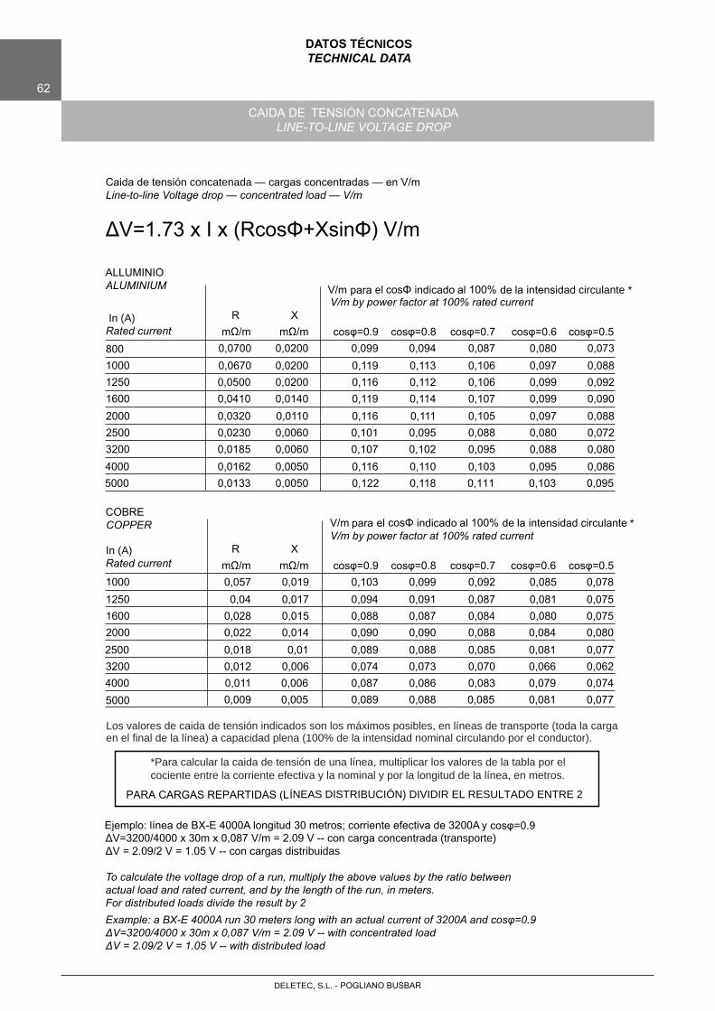
62
DATOS TÉCNICOSTECHNICAL DATA
CAIDA DE TENSIÓN CONCATENADALINE-TO-LINE VOLTAGE DROP
Caida de tensión concatenada — cargas concentradas — en V/mLine-to-line Voltage drop — concentrated load — V/m
ΔV=1.73 x I x (RcosΦ+XsinΦ) V/m
ALLUMINIOALUMINIUM
In (A)Rated current
V/m para el cosΦ indicado al 100% de la intensidad circulante *V/m by power factor at 100% rated current
R XmΩ/m mΩ/m cosφ=0.9 cosφ=0.8 cosφ=0.7 cosφ=0.6 cosφ=0.5
800 0,0700 0,0200 0,099 0,094 0,087 0,080 0,0731000 0,0670 0,0200 0,119 0,113 0,106 0,097 0,0881250 0,0500 0,0200 0,116 0,112 0,106 0,099 0,0921600 0,0410 0,0140 0,119 0,114 0,107 0,099 0,0902000 0,0320 0,0110 0,116 0,111 0,105 0,097 0,0882500 0,0230 0,0060 0,101 0,095 0,088 0,080 0,0723200 0,0185 0,0060 0,107 0,102 0,095 0,088 0,0804000 0,0162 0,0050 0,116 0,110 0,103 0,095 0,086
COBRECOPPER
In (A)
Rated current
V/m para el cosΦ indicado al 100% de la intensidad circulante *V/m by power factor at 100% rated current
R XmΩ/m mΩ/m cosφ=0.9 cosφ=0.8 cosφ=0.7 cosφ=0.6 cosφ=0.5
1000 0,057 0,019 0,103 0,099 0,092 0,085 0,0781250 0,04 0,017 0,094 0,091 0,087 0,081 0,0751600 0,028 0,015 0,088 0,087 0,084 0,080 0,0752000 0,022 0,014 0,090 0,090 0,088 0,084 0,0802500 0,018 0,01 0,089 0,088 0,085 0,081 0,0773200 0,012 0,006 0,074 0,073 0,070 0,066 0,0624000 0,011 0,006 0,087 0,086 0,083 0,079 0,0745000 0,009 0,005 0,089 0,088 0,085 0,081 0,077
PARA CARGAS REPARTIDAS (LÍNEAS DISTRIBUCIÓN) DIVIDIR EL RESULTADO ENTRE 2
Ejemplo: línea de BX-E 4000A longitud 30 metros; corriente efectiva de 3200A y cosφ=0.9ΔV=3200/4000 x 30m x 0,087 V/m = 2.09 V -- con carga concentrada (transporte)ΔV = 2.09/2 V = 1.05 V -- con cargas distribuidas
To calculate the voltage drop of a run, multiply the above values by the ratio betweenactual load and rated current, and by the length of the run, in meters.For distributed loads divide the result by 2Example: a BX-E 4000A run 30 meters long with an actual current of 3200A and cosφ=0.9 ΔV=3200/4000 x 30m x 0,087 V/m = 2.09 V -- with concentrated loadΔV = 2.09/2 V = 1.05 V -- with distributed load
POGLIANO BUSBARDELETEC, S.L. -
5000 0,0133 0,0050 0,122 0,118 0,111 0,103 0,095
*Para calcular la caida de tensión de una línea, multiplicar los valores de la tabla por el cociente entre la corriente efectiva y la nominal y por la longitud de la línea, en metros.
Los valores de caida de tensión indicados son los máximos posibles, en líneas de transporte (toda la cargaen el final de la línea) a capacidad plena (100% de la intensidad nominal circulando por el conductor).

63
DECLARACIÓN DE CONFORMIDADDECLARATION OF CONFORMITY
Declara que los productos:Herewith declares that the products:
BX-E BX-R BX-FCumplen las disposiciones de la directiva comunitaria:Comply to the provisions of the following EU directive:
N° 2006/95/CEDirectiva del Parlamento Europeo y del Consejo del 12 de diciembre de 2006 referente a la unificación de las legislaciones de los Estados Miembros relativas a materiales eléctricos.Directive of European Parliament and of member States relating to electrical equipment.
Cumplen las normas armonizadas que se enumeran a continuación:The harmonized standards listed below have been applied:
CEI EN 61439-1Conjuntos de aparellaje de protección y maniobra para baja tensión (cuadros BT)Parte 1: Reglas generalesLow-voltage switchgear and controlgear assembliesPart 1: General rules
CEI EN 61439-6Conjuntos de aparellaje de protección y maniobra para baja tensión (cuadros BT)Parte 6: Canalizaciones eléctricas prefabricadas (blindos)Low-voltage switchgear and controlgear assembliesPart 6: Busbar trunking systems (busways)
CEI EN 60529Grado de protección de las envolventesDegree of protection provided by enclosures (IP code)
POGLIANO BUSBARDELETEC, S.L. -
64
CERTIFICADOSCERTIFICATE
POGLIANO BUSBARDELETEC, S.L. -
Solicite los certificados que se requieran en cada caso a DELETEC, S.L.
DELETEC, S.L.Avda. Sabino Arana, 71 (Bajo)48012 Bilbao (Bizkaia)Tel. 944 41 15 44Fax 944 41 18 38www.blindos.com
BX-E - ed.01/2016 - IT/EN - cod. D099829550


![û6^BX]BX M±K - pku.edu.cn](https://img.pdfslide.us/doc/110x75/61736064a433c678797cd078/6bxbx-mk-pkueducn.jpg)