Embed Size (px)
Citation preview

Part number 550-141-935/1009Part No. 550-141-935/0215
– 80 – Water & Steam Boilers
For Gas, Light Oil, & Gas/Light Oil-Fired Burners
Boiler Manual
This manual must only be used by a qualified heating installer/service technician. Read all instructions before installing. Follow all instructions in proper order. Failure to comply could result in severe personal injury, death or substantial property damage.
by the consignee.
INSTALLER
USER

Weil-McLain 80 Boiler For Gas, Light Oil, Gas/Light Oil Fired Burners
2 Part No. 550-141-935/0215
The following defined terms are used throughout this manual to bring attention to the presence of hazards of
Indicates presence of hazards that personal injury, death or substantial property damage if ignored.
Indicates presence of hazards that personal injury, death or substantial property damage if ignored.
Indicates presence of hazards that personal injury, death or substantial property damage if ignored.
Indicates special instructions on installation, operation or maintenance that are important but not related to personal injury.
Read all instructions before installing. Failure to follow all instructions in proper order can cause severe personal injury, death or substantial property damage.
Do not use petroleum-based cleaning or sealing components in boiler system. Severe damage to system components can result, causing substantial property damage.
Contents
1. Before installing boiler ..................................................................32. Set boiler in place ..........................................................................53. Assemble block..............................................................................64. Perform hydrostatic pressure test .................................................85. Complete block assembly ..............................................................9��� ������� ��� ���� .....................................................................107. Connect water boiler piping ........................................................148. Connect steam boiler piping ........................................................169. Install jacket ................................................................................2010. Pipe tankless heaters ...................................................................2711. Install water boiler controls .........................................................2812. Install steam boiler controls ........................................................2913. Connect breeching and venting system.......................................3114. Install burner ...............................................................................3215. Wiring and fuel piping ..................................................................32���� �� ���������� ��� ................................................................3217. Dimensions and ratings ...............................................................3418. Parts ............................................................................................36� �������� ������� ������� ������� ��� ..........................38
Page

3Part No. 550-141-935/0215
electrical codes.
a. Fuel supplyb. Electrical powerc. System water or steam pipingd. Venting systems - see page 31
“Provide combustion and ventilation air supply openings” on page 4.
materials, gasoline and other flammable vapors and liquids.
of combustible materials, gasoline and other flammable liquids and vapors can result in severe personal injury, death and substantial property damage.
1 Before installing boiler
1. Single-wall vent pipe – 18 inches.2. Double-wall vent pipe – refer to vent pipe
manufacturer’s recommendations for vent pipe clearances.
34 inches.
servicing and burner installation. See burner literature for length and recommended service clearances.
Boiler foundation
Boiler foundation (see Figure 1)
Floor construction and condition must be suitable for weight of boiler when filled with water. See page 34 for approximate boiler operating weight.
2. Non-level conditions exist.
“L
(inches)
“L
(inches)
380 23 880 58
480 30 980 65
580 37 72
680 44 79
780 51 86

Weil-McLain 80 Boiler For Gas, Light Oil, Gas/Light Oil Fired Burners
4 Part No. 550-141-935/0215
Before installing boiler (continued)1 Combustion and ventilation air openings
— Boiler room below grade
Combustion and ventilation air openings — Boiler room partially or completely above grade
Do not install an exhaust fan in boiler
ventilation air must be provided to assure proper combustion and prevent
monoxide emissions, causing severe personal injury or death.
Opening sizes must comply with state, provincial or local codes. In their absence, use the following when
one within 12 inches of ceiling, one within 12 inches of floor. Minimum dimension of each opening is 3 inches.
opening should be at least one square inch/1,000
having adequate infiltration from outside.
should connect directly or by ducts from outdoors or crawl or attic spaces that freely connect with
a. through outside wall or vertical ducts - at least
b. through horizontal ducts - at least one square
c. where ducts are used, they should be same cross-sectional area as free area of openings they are connected to.
when calculating free air openings. Refer to their manufacturer’s instructions for size. If
-ment to prove open before boiler operation.
sidewall openings, ensure openings comply with Fig-ures 2 and 3.

5Part No. 550-141-935/0215
2
piped.
The boiler contains ceramic fiber and fiberglass materials. Use care when handling these materials per instructions on page 38 of this manual. Failure to comply could result in severe personal injury.
rails.
crane.
angles to roll boiler.
foundation, if used.
to remove cables can result in severe personal injury, death or substantial property damage.
7. Proceed to “Perform hydrostatic pressure test,” page 8.
rails.
crane.
foundation, if used.
to remove cables can result in severe personal injury, death or substantial property damage.
gas-tight seal of flue collector hood and cleanout plates.
Gas tight seal must be maintained to
carbon monoxide emissions, resulting in severe personal injury or death.
through unsealed areas.
distributor or sales office before continuing installation.
7. Proceed to “Perform hydrostatic pressure test,” page 8.
Lifting weights
Boiler model
number
Packaged boiler
lbs.Assembled block
lbs.
380 1355 1150
480 1615 1385
580 1875 1620
680 2130 1855
780 2390 2090
880 2650 2325
980 2910 2560
1080 3165 2795
1180 3425 3030
1280 3680 3265

Weil-McLain 80 Boiler For Gas, Light Oil, Gas/Light Oil Fired Burners
6 Part No. 550-141-935/0215
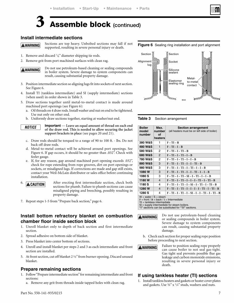
Assemble block3 Sections are top heavy. Unbolted sections
may fall if not supported, resulting in severe personal injury or death.
Figure 4.
observation port opening.
1/8” continuous bead of sealing rope adhesive in sealing rope grooves. See Figure 4.
.
at 1” intervals and push together. Do not stretch.
Do not pre-cut rope. Gas tight seal must be maintained to prevent possibility of
emissions, causing severe personal injury or death.
3. Remove any grit from port machined surfaces with clean rag.
Sealing rope installation Silicone sealant
Do not use petroleum-based cleaning or sealing compounds in boiler system. Severe damage to system components can result, causing substantial property damage.
4. Place 7½” and 3½” sealing rings in appropriate port openings. See Figure 4. If sealing ring slips out of groove, stretch ring gently for several seconds, then reposition in groove.
than 1/16” around entire outside edge of machined surface of port. Refer to Figure 5.
.
Silicone sealant applied as specified above prevents unburned oil vapors from coming in contact with sealing ring. Vapor contact can damage rings, resulting in severe damage to boiler and substantial property damage.
screw 3” pipe at least 22” long into 3” return tapping.
7Part No. 550-141-935/0215
Sections are top heavy. Unbolted sections may fall if not supported, resulting in severe personal injury or death.
1. Remove and discard 3/8” diameter shipping tie rods.
2. Remove grit from port machined surfaces with clean rag.
Do not use petroleum-based cleaning or sealing compounds in boiler system. Severe damage to system components can result, causing substantial property damage.
See Figure 6.
5. Draw sections together until metal-to-metal contact is made around
a. Oil threads on 4 draw rods. Install washer and nut on end to be tightened. Use nut only on other end.
b. Uniformly draw sections together, starting at washer/nut end.
Leave an equal amount of thread on each end of the draw rod. This is needed to allow securing the jacket support brackets in place
c. Draw rods should be torqued to a range of 90 to 100 ft. - lbs. Do not
d. Metal-to-metal contact will be achieved around port openings. See
feeler gauge.e. If, for any reason, gap around machined port opening exceeds .032”,
installation.
6. sections for plumb. Failure to plumb sections can cause misaligned piping and breeching, possibly resulting in property damage.
Assemble block (continued)3Sealing ring installation and port alignment
Section arrangement
1. Follow “Prepare intermediate section” for remaining intermediate and front
a. Remove any grit from threads inside tapped holes with clean rag.
section.
section are installed.
Do not use petroleum-based cleaning or sealing compounds in boiler system. Severe damage to system components can result, causing substantial property damage.
before proceeding to next section.
Failure to position sealing rope properly can cause boiler to not seal gas-tight. Gas tight seal prevents possible flue gas
resulting in severe personal injury or death.
3/8” x 3/4” studs, washers and nuts.

Weil-McLain 80 Boiler For Gas, Light Oil, Gas/Light Oil Fired Burners
8 Part No. 550-141-935/0215
2. Plug remaining tappings.
Do not pressure test with any control installed. Damage to control can occur due to overpressure.
3. Fill boiler. Vent
Steam
Water 1½ ti
Do not exceed above test pressures by more than 10 psig.
pressure, resulting in severe personal injury, death or substantial property damage.
substantial property damage.
Do not use petroleum-based cleaning or sealing compounds in boiler system. Severe damage to system components can result, causing substantial property damage.
5. Drain boiler and remove air vent, boiler drain and gauge. Remove plugs from tappings that will be used for controls and accessories.
4

9Part No. 550-141-935/0215
of four holes located around opening.b. Remove nuts.c. Repeat steps a and b for remaining studs.
1/8” continuous bead of sealing rope adhesive in groove around opening in section.b. Position ½” sealing rope in groove. Overlap ends at least one inch.c. Install burner mounting plate. Use ½” washers and nuts.
1/8” continuous bead of sealing rope adhesive in groove on observation port.b. Position 3/8” sealing rope in groove.c. Secure assembly to section. Use 5/16 “ - 18 x ¾” slotted head screws.
and carbon monoxide emissions, resulting in severe personal injury or death.
nuts.
3. Mount cleanout plate over opening. Secure with nuts and washers.
4. Repeat steps 1 through 3 for remaining cleanout plates.
5
Cleanout plate assembly The boiler contains ceramic fiber
and fiberglass materials. Use care when handling these materials per instructions on page 38 of this manual. Failure to comply could result in severe personal injury.

Weil-McLain 80 Boiler For Gas, Light Oil, Gas/Light Oil Fired Burners
10 Part No. 550-141-935/0215
6
Collector hood preparation
Flue collector sealing rope installation
1. Figure 10, page 11, shows flue collector components and locations. Figure 11, page 13, shows collector hoods for all models. Follow all instructions in this manual to ensure correct installation of the flue collector.
2. Model 80 boilers are available with either rear flue or top flue. Verify that you have the correct components for your application. You can convert a Model 80 from rear to top or top to rear flue using a flue conversion
The flue outlet for top flue models must be located as shown in this manual.
bolt assembly at each section joint, and on both sides of the boiler section assembly. Set aside the flanged nuts for securing the collector assembly when it is ready.
2. Each hold-down bolt assembly consists of a 5/16” x 2” carriage bolt, flat washer, regular hex nut and a flanged nut as shown.
otherwise damaged. These conditions can
monoxide emissions, resulting in severe personal injury or death.
The boiler contains ceramic fiber and fiberglass materials. Use care when handling these materials per instructions on page 38 of this manual. Failure to comply could result in severe personal injury.
4) on end as in Figure 8, left side.
) on flange.
bolt holes. Secure with seven 5/16” x 5/8” flanged bolts and flanged nuts.
. on page 12, top right column.)
a. Stand remaining hood module on end, as in Figure 8, right side.
e. Secure with seven 5/16” x 5/8” flanged bolts and flanged nuts.
.12.)
and oil.
rope around corners. .
joints must be sealed gas-tight to prevent
monoxide emissions, resulting in severe personal injury or death.
excess rope.
Double-faced tape serves only to hold sealing rope in place during installation. It will disintegrate over time. If collector hood and sealing rope are removed for any reason, install new tape and new

11Part No. 550-141-935/0215
(continued)6Flue collector components, typical (Model 880 collector configurations shown)

Weil-McLain 80 Boiler For Gas, Light Oil, Gas/Light Oil Fired Burners
12 Part No. 550-141-935/0215
(continued)61. See Figure 10, page 11, for general assembly of flue
collector components.2. See Figure 11, page 13 for the placement of flue collector
hoods on each model.3. Prepare mounting holes in boiler rear section.
a. The boiler rear section has tapped holes for mounting rear flue collector component.
b. Remove any grit from threads inside tapped holes with clean rag.
1. See Figure 10, page 11 and Figure 11, page 13.
flange surfaces with a clean rag.
hood transition flange.c. Place the
Figure 10) on the collector hood transition flange.
firmly in place.
rear section, aligning collector hood transition flange holes with tapped holes in boiler rear section.
e. Insert a 5/16” x 5/8” flanged bolt through the bottom center hole and finger tighten to hold transition in place.
f. Install six remaining bolts securing collector hood transition to rear section. only.
with the hold-down bolts in the sections.b. Place the collector hood assembly so its rear flange is
c. Thread flanged nuts onto hold-down bolts and only.
d. Insert five 5/16” x 5/8” flanged bolts through holes in collector hood transition and collector hood assembly rear flange. Thread on nuts and only.
a. Gradually tighten all bolts and nuts on flue collector assembly and boiler.
. See , upper right.
ensure all parts are evenly drawn down, with no gaps or distortion of parts.
flange surface with a clean rag.
securing. c. Position flue damper assembly against collector hood
transition. Insert a #10 x ½” screw through the top
position.d. Insert remaining #10 screws into flue damper flange
tighten all screws evenly and securely.
steps 5a through 5d.
1. See Figure 10, page 11 and Figure 11, page 13.
c. Place the
holes with tapped holes in boiler rear section.e. Insert a 5/16” x 5/8” flanged bolt through the bottom center hole and finger
tighten to hold rear flue cap in place.f. Install six remaining bolts securing rear flue cap to rear section.
only.
holes in collector hood flanges with the hold-down bolts in the sections.b. Place the collector hood assembly so its rear flange is against the rear flue
b. Thread flanged nuts onto hold-down bolts and only.c. Insert five 5/16” x 5/8” flanged bolts through holes in rear flue cap and
collector hood assembly rear flange. Thread on nuts and only.
a. Gradually tighten all bolts and nuts on flue collector assembly and boiler. . See , above.
drawn down, with no gaps or distortion of parts.
flange surface and flue collector assembly surfaces with a clean rag.
b. Position in the flue location shown in Figure 11, page 13
screws evenly and securely.
assembly with the damper adjustment plate pointed toward the rear of the boiler as shown in Figure 11. Otherwise, the
above.
resulting in severe personal injury or death.
a. Open flue damper. Visually inspect inside section assembly and flue collector assembly for any light passing through unsealed areas.
place, or loose bolts or nuts.
e. If unsealed areas cannot be eliminated, discontinue the boiler installation.
DO NOT overtighten bolts in flue collector hood assembly.
and carbon monoxide emissions, resulting in severe personal injury or death.

13Part No. 550-141-935/0215
Flue collector components by model (see Figure 10, page 11 for flue collector components not shown below)
6 (continued)

Weil-McLain 80 Boiler For Gas, Light Oil, Gas/Light Oil Fired Burners
14 Part No. 550-141-935/0215
7
ASME drain valve size
Recommended minimum pipe sizes for known flow rates.
Recommended minimum pipe sizes when flow rate is not known (see Figure 12)
Water boiler piping, typical
������������GPM
Supply pipe size
A
Return pipe size
B
Up to 35 2” 2”
36–50 2½” 2½”
51–77 3” 3”
78–142 4” 4”
Boiler model number Valve size
380 – 480 ¾”
580 – 1180 1”
1280 1¼”
Boiler model number Supply pipe size
A
Return pipe size
B
380 2” 2”
480 2½” 2½”
580– 680 3” 3”
780–1280 4” 4”
water flow through boiler that must not be used.
Install piping as shown in Figure 12 for single boilers. For multiple boilers, see Figure 13, page 15.
Improperly piped systems or undersized piping can contribute to erratic boiler operation and possible boiler or system damage.
a. Size according to tables below.1) For , size piping per Table below, using 20°F.
temperature rise through boiler.2) For through boiler, size
piping per Table below.
Flow at higher rates than shown in Table below for pipe size can damage boiler, causing substantial property damage.
c. For return piping, use full diameter pipe for 10 times that diameter
be reduced any closer to boiler return tapping than 40 inches.
a.
at least 1 inch per each 5 feet of piping.b.

15Part No. 550-141-935/0215
(continued)7A Size secondary boiler pump GPM based on
degree elbows of secondary pipe size. Operate each
boiler control panel. maintain boiler at predetermined water temperature.
B Primary pump GPM and head calculation should not include secondary boiler circuits. Primary pump can operate continuously during heating season.
C Space 12” maximum or as close as practical.DE Hand valve.
are required but not shown.
Multiple water boiler piping
, °F = 230°F – Return water temperature
is in Btuh.

Weil-McLain 80 Boiler For Gas, Light Oil, Gas/Light Oil Fired Burners
16 Part No. 550-141-935/0215
8
Steam boiler pipe size for typical 2-pipe steam systems
required for steam boilers. Use the Hartford loop for both pumped-return and gravity-return systems.
energized by boiler-mounted pump controller. Install
Install piping as shown on pages 16 through 18 for single boilers. See page 19 for additional requirements when piping multiple boilers.
Improperly piped systems or undersized piping can contribute to erratic boiler operation and possible boiler or system damage. Piping system must be installed as shown, using pipe sizes shown. Pipe sizes shown are for two-pipe, pumped-
needed when connecting to gravity-re-
distributor or sales office before installing alternate piping.
a. See Table 7.1) Size condensate return piping by pump.2) Size gravity condensate return same as equalizer
“J” pipe size.b. Install system drain valve in lowest part of return
shown in Table 6, page 14.
a. Satisfactory operation of any steam heating system depends on adequate return of condensate to maintain steady water level.
water.
water cutoff with pump control, condensate receiver, and condensate boiler feed pump should be installed. Refer to page 18, Figure 18 for piping and Table 8 for sizing.
3. Multiple steam boiler pipinga. See page 19.
Cold water fill piping
Figure number Boiler model
numberRiser pipe size
inches Note 1
“H”
Header
inches
Note 2
“J”
Equalizer
inches
A B C
15
380 3 -- -- 3 2
480 4 -- -- 4 2
580 4 -- -- 4 2 ½
16
680 3 3 -- 4 2 ½
780 4 4 -- 4 2 ½
880 4 4 -- 4 3
980 4 4 -- 6 3
17 1080-1280 4 4 4 6 3
Notes:1. Based on ASHRAE Handbook recommendations, allowing ½ oz. pressure drop per 100 feet of pipe for dry return.
2. Based on ASHRAE Handbook recommendations, allowing 2 oz. pressure drop per 100 feet of pipe at 3.5 psig. Maintain minimum 24” height from waterline to header.

17Part No. 550-141-935/0215
(continued)8Model 380 through 580 steam boiler piping — NOTE minimum 24 inches between boiler water line and bottom of header.
Model 680 through 980 steam boiler piping — NOTE minimum 24 inches between boiler water line and bottom of header.

Weil-McLain 80 Boiler For Gas, Light Oil, Gas/Light Oil Fired Burners
18 Part No. 550-141-935/0215
Condensate receiver capacity Condensate piping to boiler
(continued)8 Model 1080 through 1280 steam boiler piping — NOTE minimum 24 inches between boiler water line and
bottom of header.
Boiler model
number
AHRI gross output
(lbs steam per hour)
Gallons condensate
per hour
Minimum condensate receiver capacity (gallons) (Note 1)
Recommended condensate feed pump capacity
GPM at 15 PSI15-minute
boiler operation
30-minute boiler
operation
45-minute boiler
operation
60-minute boiler
operation
380 278 33 11 21 31 41 1.2
480 396 48 15 29 43 58 1.6
580 515 62 19 38 56 75 2.1
680 634 76 23 46 69 92 2.6
780 753 90 28 55 82 109 3.1
880 872 105 32 63 95 126 3.5
980 991 119 36 72 108 143 4.0
1110 133 40 80 120 160 4.5
1229 148 45 89 133 178 5.0
1348 162 49 98 146 195 5.4
Note 1 — Maximum time to when condensate returns to boiler.

19Part No. 550-141-935/0215
Multiple Steam Boiler Piping Gravity Condensate Return
(continued)8
A Pipe as shown for gravity return systems, connecting point A to the wet gravity return.
For pumped-return systems, install boiler water level
in Figure 30 on page 30. Provide at point A
boiler, or . . .
each boiler.
B For pumped-return systems, install a combination float and thermostatic trap on each boiler to prevent flooding of one boiler while other boiler is firing. Install
condensate receiver.
Gravity-return systems are self-levelling if the wet returns are piped to the common system wet return.
Cthrough 19).
D For pump-return systems, if using automatic steam
valves, use only slow-opening automatic valves. Use
panel) to open each steam valve automatically before firing burner.
Eat least same size as largest boiler header size.
F
G Install drip line in common supply drop header.
trap and drain to condensate receiver.

Weil-McLain 80 Boiler For Gas, Light Oil, Gas/Light Oil Fired Burners
20 Part No. 550-141-935/0215
9
manual.
tapping table, page 28 or 29.
through 19.
installed. See pages 9 through 13.
The boiler contains ceramic fiber and fiberglass materials. Use care when handling these materials per instructions on page 38 of this manual. Failure to comply could result in severe personal injury.
cartons as long as possible to avoid damage.
as shown in Figure 20, page 21.
2. Fasten securely with 5/8” nuts where shown.
Models 380, 480, 580, 680 and 780 do
are close to an equal number of sections on either side
boiler by securing with #10 x ½” Phillips pan head screws. tighten the screws more than finger-tight.
and lower channels using #10 x ½” Phillips pan head screws, as shown in Figure 20.
2.
installing on boiler.

21Part No. 550-141-935/0215
Installing jacket support brackets and rails and jacket front and rear panels
(continued)9

Weil-McLain 80 Boiler For Gas, Light Oil, Gas/Light Oil Fired Burners
22 Part No. 550-141-935/0215
Installing (removing) jacket side panels and top panels
(continued)9
Figure 21.
side panel, front panel and rails is square.
alignment.
rails.
or 24.
snips.
3. Install trim collar around damper assembly on top flue boilers.
faces toward the boiler.
23Part No. 550-141-935/0215
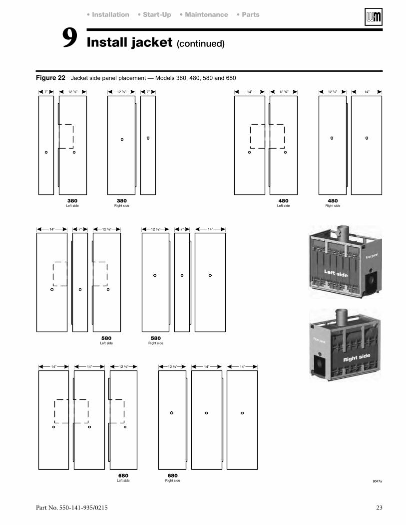
Jacket side panel placement — Models 380, 480, 580 and 680
(continued)9
Weil-McLain 80 Boiler For Gas, Light Oil, Gas/Light Oil Fired Burners
24 Part No. 550-141-935/0215
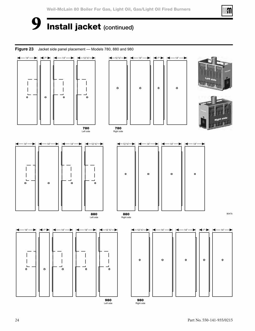
Jacket side panel placement — Models 780, 880 and 980
(continued)9

25Part No. 550-141-935/0215
Jacket side panel placement — Models 1080, 1180, and 1280
(continued)9

Weil-McLain 80 Boiler For Gas, Light Oil, Gas/Light Oil Fired Burners
26 Part No. 550-141-935/0215
Jacket top panel placement
(continued)9

27Part No. 550-141-935/0215
Tankless Heater Ratings
Tankless Heater Piping
10
Tankless
heater model
��� ���������(no recovery period)
GPM
Inlet and outlet tappings
78-24 6.5 ¾”
temperature of 130°F or less.
comply with valve manufacturer’s recommendations and instructions.
needs will scald and cause injury.
children to use a hot water faucet or draw their own bath. If anyone using hot water in the building fits this description, or if state laws or local codes require certain water temperatures
Install automatic mixing valve set according to those standards.
1. Size piping no smaller than heater inlet and outlet.
Figure 26. Follow manufacturer’s instructions to install.
3. Flow regulating valve must be installed. Size according to continuous draw of heater. See Table 9. Follow manufacturer’s instructions to install.
4. Operating control with small adjustable differential scale is recommended. Install in temperature control tapping in heater plate.
a. Use cold water supply header with individual risers to each heater. Size header by increasing one pipe size for each additional heater.
b. Use hot water outlet header with individual risers to each heater. Size header by increasing one pipe size for each additional heater.
c. Do not pipe multiple heaters in series.
6. In hard water areas, soften cold domestic water supply to heaters to prevent lime build-up.

Weil-McLain 80 Boiler For Gas, Light Oil, Gas/Light Oil Fired Burners
28 Part No. 550-141-935/0215
11Water control tappings (see Figure 27)
Water control locations
1. Install furnished controls where shown in Table 10 and Figure 27.
Failure to properly install, pipe and wire boiler controls can result in severe damage to boiler, building and personnel; and is not covered by boiler warranty.
2. Relief valve must be installed with spindle in vertical
any other connection in that piping.
Relief valve discharge line must be piped using rigid material suitable for 375°F, threaded one end, near floor close to drain to eliminate potential of severe burns. Do not pipe to any area where freezing could occur. Do not plug, valve or place any obstruction in discharge line.
a. Must be installed if boiler is located above radiation level.b. May be required on water boilers by certain state,
local or territorial codes or insurance companies.c. Install low water cutoff designed for water
installations where shown in Table 10 and Figure 27.
requirements, an additional high temperature limit is needed. Purchase and install in supply line between boiler and isolation valve or in tapping “A.”
– set according to design requirements. – at least 20° higher than low limit, 240°F
maximum.
6. Install optional controls per control manufacturer’s instructions.

29Part No. 550-141-935/0215
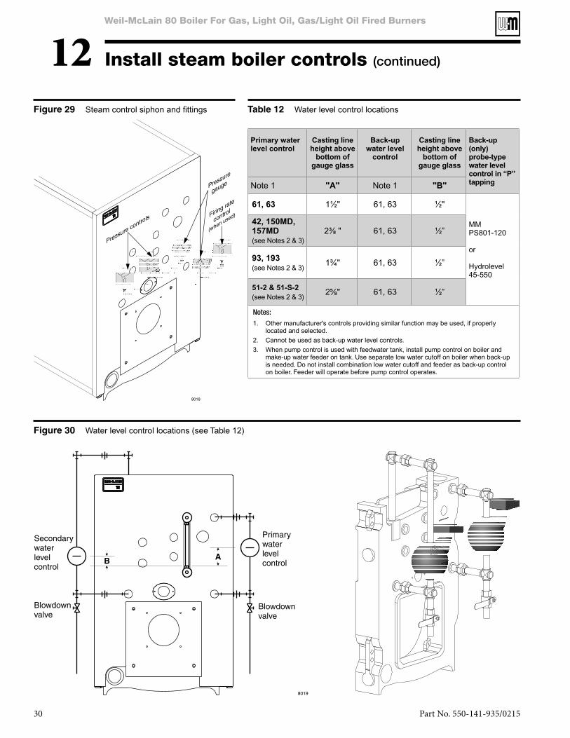
12Steam control tappings (see Figure 28)
Steam control locations
1. Install controls where shown in Table 11 and Figure 28.
Failure to properly install, pipe and wire boiler controls can result in severe damage to boiler, building and personnel; and is not covered by boiler warranty.
a. Install steam pressure operating and high limit controls and pressure gauge. See Figure 28,this page, and Figure 29, page 30.
– set according to design requirements. – set at least 2 psi higher than low limit,
15 psi maximum.b. Relief valve must be installed with spindle in vertical
position. Use fittings provided with boiler. Do not
Pipe relief valve discharge through vertical piping to atmosphere. Use rigid material suitable for 375°F, threaded one end only. Install drain pan elbow to drain condensate. Pipe near floor close to floor drain to eliminate potential of severe burns. Do not pipe to any area where freezing could occur. Do not plug, valve or place any obstruction in discharge line.
c. Install water level controls and gauge glass as shown in Figure 30 and Table 12, page 30.1. Fittings for controls to be furnished by others.2. If water level control is not shown in Table 12,
install per manufacturer’s instructions.
will occur.
Weil-McLain 80 Boiler For Gas, Light Oil, Gas/Light Oil Fired Burners
30 Part No. 550-141-935/0215
(continued)12Steam control siphon and fittings Water level control locations
Water level control locations (see Table 12)
�� ����������level control
Casting line
height above
bottom of
gauge glass
Back-up
�����������control
Casting line
height above
bottom of
gauge glass
Back-up
(only)
probe-type
���������� control in “P”
tappingNote 1 "A" Note 1 "B"
61, 63 1½" 61, 63 ½"
MM PS801-120 or Hydrolevel 45-550
42, 150MD, 157MD(see Notes 2 & 3)
���� 61, 63 ½”
93, 193(see Notes 2 & 3)
1¾" 61, 63 ½”
51-2 & 51-S-2
(see Notes 2 & 3)��� 61, 63 ½”
Notes:1. Other manufacturer's controls providing similar function may be used, if properly
located and selected.2. Cannot be used as back-up water level controls.3. When pump control is used with feedwater tank, install pump control on boiler and
make-up water feeder on tank. Use separate low water cutoff on boiler when back-up is needed. Do not install combination low water cutoff and feeder as back-up control on boiler. Feeder will operate before pump control operates.

31Part No. 550-141-935/0215
13
Stub vent – forced draft — single boiler
Conventional chimney – balanced draft with barometric draft control when required — single boiler
Stub vent – forced draft — multiple boilers
Conventional chimney – balanced draft with barometric draft control when required — multiple boilers
Minimum breeching diameter — forced draft venting
Minimum breeching diameter — balanced draft venting
Boiler
model
number
AHRI recommended
minimum vent
diameter
Flue collar outlet
diameter
(inches) (inches)
380 6 8
480 7 8
580 8 8
680 8 8
780 9 10
880 10 10
980 10 10
1080 10 10
1180 10 10
1280 12 12
Boiler
model
number
AHRI
round vent
diameter
AHRI
rectangle
chimney
size
Minimum
chimney/
vent
height
Flue collar
outlet
diameter
(inches) (inches) (feet) (inches)
380 8 8 x 12 15 8
480 10 8 x 12 15 8
580 10 12 x 12 15 8
680 11 12 x 16 15 8
780 12 12 x 16 15 10
880 15 12 x 16 15 10
980 15 16 x 16 15 10
1080 15 16 x 16 15 10
1180 15 16 x 16 15 10
1280 15 20 x 16 15 12
be limited to prevent negative draft with 3-foot minimum stub vent height above roof. See Figures 31 and 32.
provide excess draft which may require a barometric draft con-trol installed and set to provide minimum draft to maintain 0.1” positive pressure at flue collar. Minimum chimney height above roof is 3 feet. See Figures 33 and 34.
through seams and joints, resulting in severe personal injury or death.
and construction and lining.
tees and elbows or other obstructions restricting combustion gas flow can result in possibility
monoxide emissions, causing severe personal injury or death.

Weil-McLain 80 Boiler For Gas, Light Oil, Gas/Light Oil Fired Burners
32 Part No. 550-141-935/0215
14
16
15
If sealing rope is used, apply 1/8” continuous bead of rope adhesive
gas-tight seal.
3. Mount burner into opening in burner mounting plate.
Maintain gas-tight seal between burner mounting flange and plate to prevent damage to air tube.
5. Secure with furnished bolts.
injury or death if power source is not disconnected before installing or servicing boiler and burner.
2. Follow burner manual and wiring diagram found in burner
3. Use 14 ga. wire for operating and safety circuit wiring.
3. Oil piping – use flare-type fittings, not compression type.
Do not use compression or soldered fittings. No safe repair can be made. Severe personal injury, death or substantial property damage will result.
regarding propane gas odorant.
assure proper operation. Do not fire boiler without water. Sections will overheat, damaging boiler and resulting in severe property damage.
2. Refer to burner manual for start-up and service.
2
2
at test opening. Tighten screws to secure in position. Plug test opening with 3/8” bolt provided with damper assembly.
pressure will vary with each installation.
3. Starting on lowest floor, open air vents one
Repeat with remaining vents.
4. Refill boiler to correct pressure.
boiler is ready to be fired.
2. Fill to normal waterline, halfway up gauge glass.
3. Recommend boiler water pH 7.0 to 8.5.

33Part No. 550-141-935/0215
(continued)16Flue damper assembly, typical
remove oil. Failure to properly clean can result in violent water level fluctuations, water passing into steam mains, or high maintenance costs on strainers, traps and
Do not use petroleum-based cleaning or sealing compounds in boiler system. Severe damage to system components can result, causing substantial property damage.
A” –
3. Fire burner to maintain temperature below steaming
prevent rise in steam pressure.
, flush all interior surfaces under full pressure until drain water runs clear.
tapping.
line. Start burner and steam for 15 minutes to remove dissolved gases. Stop burner.
Do not use petroleum-based cleaning or sealing compounds in boiler system. Severe damage to system components can result, causing substantial property damage.
-erals can build up in sections, reducing heat transfer, overheating cast iron and causing section failure.
For unusually hard water areas or low pH conditions
1. Use antifreeze especially made for hydronic systems. Inhibited propylene glycol is recommended.
Do not use automotive, ethylene glycol or undiluted antifreeze. Severe personal injury or death can result.
disconnect from city water supply.
4. Determine quantity according to system water content.
solution will affect sizing of heat distribution units,
5. Follow antifreeze manufacturer’s instructions.
monoxide emissions, resulting in severe personal injury or death.
The boiler contains ceramic fiber and fiberglass materials. Use care when handling these materials per instructions on page 38 of this manual. Failure to comply could result in severe personal injury.
any not gas-tight.
a. use silicone sealant on section flueways.

Weil-McLain 80 Boiler For Gas, Light Oil, Gas/Light Oil Fired Burners
34 Part No. 550-141-935/0215
Dimensions and ratings17
1. Burner input based on maximum of 2,000 feet altitude. For higher altitudes consult local Weil-McLain representative.2. No. 2 fuel oil Commercial Standard Spec. CS75-56. Heat value of oil — 140,000 Btu/Gal.3. Consult Weil-McLain Burner Specifications and Data Sheet for gas pressures required.4. MBH refers to thousands of Btu per hour.5. Gross AHRI ratings have been determined under the AHRI provision forced draft boiler-burner units.6. Net AHRI ratings are based on net installed radiation of sufficient quantity for the requirements of the building and nothing need be added for normal piping and pickup.
Water ratings are based on a piping and pickup allowance of 1.15. Steam ratings are based on the following allowances: 380 thru 1180 — 1.333; 1280 — 1.321. An additional allowance should be made for gravity hot water systems or for unusual piping and pickup loads. Consult locat Weil-McLain representative.
7. Stack gas volume at outlet temperature.8. With 0.10” W.C. positive pressure at flue collar.
: Boiler sections are tested for 80 PSIG working pressure. Water boilers are supplied with 30 PSIG relief valve standard.
AHRI Certified Ratings
Boiler model number
AHRIburner
capacity
Gross output
Net AHRI ratings Combustionefficiency
Thermalefficiency
Boiler H.P.
Net firebox volume
Flue gas
volume
Flue outlet
diameter
Boiler water content
(gallons)
Light oil GPH
Gas MBH
MBH Steam Sq. Ft
Steam MBH
Water MBH
Oil Gas Oil GasCu. ft. CFM Inches Water
boilerSteam
to waterline
Notes: 1 2 3, 4 5, 6 5 5 % % % % — — 7 — — —
380 2.40 346 278 867 209 242 85.3 82.7 82.7 80.2 8.3 2.61 139 8 37.5 27.5
480 3.40 491 396 1238 297 344 85.5 82.9 83.2 80.7 11.8 3.97 198 8 49.0 36.0
580 4.45 639 515 1608 386 448 85.1 82.6 83.1 80.6 15.4 5.33 259 8 60.5 44.5
680 5.50 787 634 1983 476 551 84.9 82.3 83.1 80.6 18.9 6.69 320 8 72.0 53.0
780 6.50 935 753 2354 565 655 84.7 82.2 83.1 80.6 22.5 8.05 378 10 83.5 61.5
880 7.50 1082 872 2725 654 758 84.6 82.0 83.0 80.6 26.0 9.41 436 10 95.0 70.0
980 8.50 1230 991 3096 743 862 84.5 82.0 83.0 80.5 29.6 10.77 494 10 106.5 78.5
1080 9.60 1378 1110 3471 833 965 84.4 81.9 83.0 80.5 33.2 12.13 558 10 118.0 87.0
1180 10.60 1526 1229 3842 922 1069 84.4 81.8 83.0 80.5 36.7 13.49 616 10 129.5 95.5
1280 11.60 1674 1348 4242 1018 1172 84.3 81.8 83.0 80.5 40.3 14.85 675 12 141.0 104.0
Boiler model number
(inches) Packaged boiler weight
(less water)
Packaged boiler weight
(with water)
Supply tappings Qty-size (see Note)
Return tappingsQty-size (see Note) A B D F H W L
Water Steam Water Steam Lbs Lbs
380 2 – 4" 2 – 4" 2 – 3" 2 – 3” ��� -- 8 12 7/16 13 ½ ��� ���� 1058 1170
480 2 – 4" 2 – 4" 2 – 3” 2 – 3” �� -- 8 ���� 20 ½ ���� ���� 1203 1411
580 2 – 4" 2 – 4" 2 – 3” 2 – 3” ��� -- 8 ���� 27 ½ � �� ���� 1448 1752
680 2 – 4" 2 – 4" 2 – 3” 2 – 3” � � -- 8 ���� 34 ½ ��� ��� 1843 2093
780 2 – 4" 2 – 4" 2 – 3” 2 – 3” �� -- 10 ���� 41 ½ ��� � ��� 2088 2434
880 2 – 4" 2 – 4" 2 – 3” 2 – 3” �� -- 10 ���� 48 ½ ���� ���� 2317 2774
980 2 – 4" 2 – 4" 2 – 3” 2 – 3” ��� -- 10 ��� 55 ½ ���� ���� 2678 3115
1080 2 – 4" 3 – 4" 2 – 3” 2 – 3” ��� 27 9/16 10 ��� 62 ½ ���� ��� 2923 3456
1180 2 – 4" 3 – 4" 2 – 3” 2 – 3” ��� 34 9/16 10 ���� 69 ½ ���� ���� 3068 3697
1280 2 – 4" 3 – 4" 2 – 3” 2 – 3” ��� 34 9/16 12 ���� 76 ½ ���� � �� 3313 4038
NOTE: Use piping connections shown in manual pages 14 through 19.

35Part No. 550-141-935/0215
17 Dimensions and ratings (continued)

Weil-McLain 80 Boiler For Gas, Light Oil, Gas/Light Oil Fired Burners
36 Part No. 550-141-935/0215
18

37Part No. 550-141-935/0215
18 (continued)
Weil-McLain 80 Boiler For Gas, Light Oil, Gas/Light Oil Fired Burners
38 Part No. 550-141-935/0215
Handling ceramic fiber and fiberglass materials
REMOVAL OF COMBUSTION CHAMBER LINING OR BASE PANELS
-
■
for cristobalite at the time this document was written. Other types of respirators may be needed depend-
numbers are also listed on this web site.
■
■ Remove combustion chamber lining or base insulation from the boiler and place it in a plastic bag for dis-posal.
■
NIOSH stated First Aid.■
■
REMOVAL OF FIBERGLASS WOOL — OR —INSTALLATION OF FIBERGLASS WOOL, COMBUSTION CHAMBER LINING OR BASE PANELS:
as a possible cause of cancer through inhalation.
■
for fiberglass wool at the time this document was written. Other types of respirators may be needed
phone numbers are also listed on this web site.
■ Operations such as sawing, blowing, tear out, and spraying may generate airborne fiber concentration requir-ing additional protection.
■
NIOSH stated First Aid.■
■
This symbol is used in this addendum to indicate presence of hazards that can cause severe personal injury, death or substantial property damage.

39Part No. 550-141-935/0215
presence detectable. In some instances, the odorant can fade and the gas may no longer have an odor.
■ Propane gas can accumulate at floor level. Smell near the floor for the gas odorant or any
■
common.
■
■
■
appropriate device.

Weil-McLain 80 Boiler For Gas, Light Oil, Gas/Light Oil Fired Burners
40 Part Number 550-141-935/0215