Embed Size (px)
Citation preview

BMP Standards and Specifications Vegetated Channels
3.06.2.8-1
8.0 Vegetated Channels Definition: Vegetated open channels
that are designed to convey the design storm volume (RPv and Cv, may also convey the Fv as designed).
Design variants include: 8-A Bioswale 8-B Grassed Channel Vegetated channels systems shall not be designed to provide stormwater detention. Vegetated channels can provide a modest amount of runoff filtering and volume attenuation within the stormwater conveyance system resulting in the delivery of less runoff and pollutants than a traditional system of curb and gutter, storm drain inlets and pipes. The performance of vegetated channels will vary depending on the underlying soil permeability. Their runoff reduction performance can be boosted when compost amendments are added to the bottom of the channel. Vegetated channels are a preferable alternative to both curb and gutter and storm drains as a stormwater conveyance system, where development density, topography, soils, and water table permit.
FEQ July 2016

BMP Standards and Specifications Vegetated Channels
3.06.2.8-2
Figure 8.1. Typical Section for Bioswale / Grassed Channel
Figure 8.2. Example Check Dam
FEQ July 2016

BMP Standards and Specifications Vegetated Channels
3.06.2.8-3
8.1 Vegetated Channel Stormwater Credit Calculations Vegetated channels receive a variable annual runoff reduction volume credit depending upon the specific type employed (Table 8.1). No additional pollutant removal credit is awarded.
Table 8.1 Vegetated Channel Performance Credits Runoff Reduction*
Retention Allowance 0% RPv -A/B Soil or Compost Amended C Soil
Bioswale : 50% Annual Runoff Reduction Grassed Channel: 20% Annual Runoff Reduction
RPv - C/D Soil Bioswale: 25% Annual Runoff Reduction Grassed Channel: 10% Annual Runoff Reduction
Cv 10% of RPv Allowance Fv 1% of RPv Allowance
Pollutant Reduction
TN Reduction 100% of Load Reduction
TP Reduction 100% of Load Reduction
TSS Reduction 100% of Load Reduction
*See Appendix A-7 Alternative Methods for RPv Compliance for additional information on
modeling this practice using traditional hydrologic methods.
FEQ July 2016
BMP Standards and Specifications Vegetated Channels
3.06.2.8-4
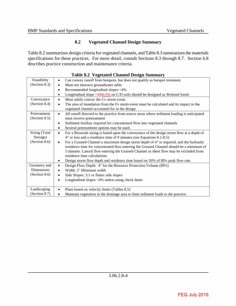
8.2 Vegetated Channel Design Summary Table 8.2 summarizes design criteria for vegetated channels, and Table 8.3 summarizes the materials specifications for these practices. For more detail, consult Sections 8.3 through 8.7. Section 6.8 describes practice construction and maintenance criteria.
Table 8.2 Vegetated Channel Design Summary Feasibility
(Section 8.3) • Can convey runoff from hotspots, but does not qualify as hotspot treatment • Must not intersect groundwater table • Recommended longitudinal slopes <4% • Longitudinal slope <1%0.5% on C/D soils should be designed as Wetland Swale
Conveyance (Section 8.4)
• Must safely convey the Cv storm event. • The area of inundation from the Fv storm event must be calculated and its impact to the
vegetated channel accounted for in the design. Pretreatment (Section 8.5)
• All runoff directed to the practice from source areas where sediment loading is anticipated must receive pretreatment
• Sediment forebay required for concentrated flow into vegetated channels • Several pretreatment options may be used.
Sizing (Total Storage)
(Section 8.6)
• For a Bioswale sizing is based upon the conveyance of the design storm flow at a depth of 4” or less and a residence time of 9 minutes (see Equations 8.1-8.5)
• For a Grassed Channel a maximum design storm depth of 4” is required, and the hydraulic residence time for concentrated flow entering the Grassed Channel should be a minimum of 5 minutes. Lateral flow entering the Grassed Channel as sheet flow may be excluded from residence time calculations
• Design storm flow depth and residence time based on 50% of RPv peak flow rate Geometry and Dimensions (Section 8.6)
• Design Flow Depth: 4” for the Resource Protection Volume (RPv) • Width: 2’ Minimum width • Side Slopes: 3:1 or flatter side slopes • Longitudinal slopes <4% unless using check dams
Landscaping (Section 8.7)
• Plant based on velocity limits (Tables 8.5) • Maintain vegetation in the drainage area to limit sediment loads to the practice.
FEQ July 2016

BMP Standards and Specifications Vegetated Channels
3.06.2.8-5
Table 8.3. Vegetated Channel Materials Specifications Component Specification
Grass
A dense cover of water-tolerant, erosion-resistant grass. The selection of an appropriate species or mixture of species is based on several factors including climate, soil type, topography, and sun or shade tolerance. Grass species should have the following characteristics: • Deep root system to resist scouring • High stem density with well-branched top growth • Water-tolerance • Resistance to being flattened by runoff • An ability to recover growth following inundation • Salt tolerant for any channel receiving runoff from roadways
Check Dams
• Check dams must be constructed of a non-erosive material such as wood, gabions, riprap, or concrete. All check dams should be underlain with filter fabric (or other support material such as stone) conforming to local design standards.
• Wood used for check dams should consist of pressure treated logs or timbers, or water-resistant tree species such as cedar, hemlock, swamp oak or locust.
• Computation of check dam material is necessary, based on the surface area and depth used in the design computations.
Energy Dissipation When conveyance velocity within the vegetated channel exceeds standard allowances, an energy dissipation device must be placed. Most commonly, energy dissipation will be required at the outlet of a piped stormwater conveyance system.
Erosion Control Fabric
Biodegradable erosion control netting or mats that are durable enough to last at least 12 months must be used, conforming to Delaware Erosion and Sediment Control Handbook.
8.3 Vegetated Channel Feasibility Criteria Vegetated channels are primarily applicable for land uses such as roads, highways, and residential development. Some key feasibility issues for vegetated channels include the following: Contributing Drainage Area. The maximum contributing drainage area to a vegetated channel should be 10 acres, and preferably less. The design criteria for maximum channel velocity and depth are applied along the entire length (See Section 8.6). It is this criteria that will determine the maximum drainage area to a specific vegetated channel. Available Space. Vegetated channel footprints can fit into relatively narrow corridors between utilities, roads, parking areas, or other site constraints. Vegetated channels can be incorporated into linear development applications (e.g., roadways) by utilizing the space typically required for an open section drainage feature. The footprint required will likely be greater than that of a typical conveyance channel, but the benefit of the runoff reduction may reduce the footprint requirements for stormwater management elsewhere on the development site. Site Topography. Vegetated channels should be used on sites with longitudinal slopes of less than 4%. Check dams can be used to reduce the effective slope of the channel and lengthen the contact time to enhance filtering and/or infiltration. Longitudinal slopes of less than 2% are ideal and may eliminate the need for check dams. However, channels designed with longitudinal slopes of less than
FEQ July 2016

BMP Standards and Specifications Vegetated Channels
3.06.2.8-6
1% should be monitored carefully during construction to ensure a continuous grade, in order to avoid flat areas with pockets of standing water. Sites with longitudinal slopes less than 1%0.5% on HSG ‘C’ or ‘D’ soils should be designed as a wetland swale in accordance with Specification 12. Constructed Wetlands. Land Uses. Vegetated channels can be used in residential, commercial, or institutional development settings. The linear nature of vegetated channels makes them well-suited to treat highway or low- and medium-density residential road runoff, if there is adequate right-of-way width and distance between driveways. Typical applications of vegetated channels include the following, as long as drainage area limitations and design criteria can be met: • Within a roadway right-of-way • Along the margins of small parking lots • Oriented from the roof (downspout discharge) to the street • Disconnecting small impervious areas Vegetated channels are not recommended when residential density exceeds more than 4 dwelling units per acre, due to a lack of available land and the frequency of driveway crossings along the channel. Vegetated channels may provide pre-treatment for other stormwater treatment practices. Hotspot Land Use. Vegetated channels can typically be used to convey runoff from stormwater hotspots, but do not qualify as a hotspot treatment mechanism. For a list of designated stormwater hotspot operations, consult Appendix 4. Available Hydraulic Head. A minimum amount of hydraulic head is needed to implement vegetated channels in order to ensure positive drainage and conveyance through the channel. The hydraulic head for vegetated channels is measured as the elevation difference between the channel inflow and outflow point. Hydraulic Capacity. Vegetated channels are typically designed as on-line practices which must be designed with enough capacity to (1) convey runoff from the Conveyance Event (Cv) and Flooding Event (Fv) design storms at non-erosive velocities, and (2) contain the Cv flow within the banks of the swale. This means that the channel’s surface dimensions are more often determined by the need to pass the Cv storm event, which can be a constraint in the siting of vegetated channels within existing rights-of-way (e.g., constrained by sidewalks). Depth to Water Table. Designers should ensure that the bottom of vegetated channels is above the
FEQ July 2016

BMP Standards and Specifications Vegetated Channels
3.06.2.8-7
seasonally high groundwater table. Soils. Soil conditions do not constrain the use of vegetated channels. However, vegetated channels situated on low-permeability soils may incorporate compost amendments in order to improve performance. Utilities. Interference with underground utilities should be avoided, particularly water and sewer lines. Approval from the applicable utility company or agency is required if utility lines will run below the vegetated channel. Floodplains. Vegetated channels should be constructed outside the limits of the 100-year floodplain. Avoidance of Irrigation or Baseflow. Vegetated channels should be located so as to avoid inputs of springs, irrigation systems, chlorinated wash-water, or other dry weather flows. 8.4 Vegetated Channel Conveyance Criteria
• The bottom width and slope of a vegetated channel should be designed such that the design storm flow depth does not exceed 4-inches. Vegetated channels shall convey the Cv and Fv at non-erosive velocities (less than 3 feet-per-second) for the soil and vegetative cover provided. Additionally tractive force calculations may be provided to show that a channel is capable of supporting velocities in excess of 3 fps in a non-erosive condition. Check dams may be provided to reduce flow velocities. If check dams are employed, flow depths should be calculated through the check dams to ensure that the maximum flow depth of 4-inches is not violated for the RPv.
• The bottom width and slope of a Bioswale should be designed such that the design storm
flow depth, 50% of RPv peak flow rate, does not exceed 4-inches, and the residence time of the flow within the channel must exceed 9 minutes. Bioswales shall convey the Cv and Fv at non-erosive velocities (less than 3 fps) for the soil and vegetative cover provided. Additionally tractive force calculations may be provided to show that a channel is capable of supporting velocities in excess of 3 fps in a non-erosive condition. The analysis should evaluate the flow profile through the channel at normal depth, as well as the flow depth over top of the check dams.
8.5 Vegetated Channel Pretreatment Criteria Pretreatment is required for vegetated channels to dissipate energy, trap sediments and slow down the runoff velocity to below maximum allowable velocity.
FEQ July 2016

BMP Standards and Specifications Vegetated Channels
3.06.2.8-8
The selection of a pre-treatment method depends on whether the channel will experience sheet flow or concentrated flow. Several options are as follows: • Grass Filter Strip (sheet flow): Grass filter strips extend from the edge of the pavement to the
bottom of the vegetated channel at a slope of 5:1 or flatter. Alternatively, provide a combined 5 feet of grass filter strip at a maximum 5% (20:1) cross slope and 3:1 or flatter side slopes on the vegetated channel.
• Gravel or Stone Flow Spreaders (concentrated flow). The gravel flow spreader may be located at curb cuts, downspouts, or other concentrated inflow points, and should have a 2 to 4 inch elevation drop from a hard-edged surface into the gravel or stone flow spreader. The gravel should extend the entire width of the opening and create a level stone weir at the bottom or treatment elevation of the channel.
• Initial Sediment Forebay (channel flow). This reinforced or otherwise stabilized cell is located at the upper end of the vegetated channel segment with a 2:1 length to width ratio and a storage volume equivalent to at least 15% of the Resource Protection event volume (RPv). Typically used when a concentrated flow from a pipe or other conveyance system enters a vegetated channel.
8.6 Vegetated Channel Design Criteria Channel Geometry. Design guidance regarding the geometry and layout of vegetated channels is provided below: • Vegetated channels should be designed with a trapezoidal or parabolic cross section. A parabolic
shape is preferred for aesthetic, maintenance, and hydraulic reasons. • The bottom width of the channel should be at a minimum of 2 feet wide to ensure that an
adequate surface area exists along the bottom of the channel for filtering. If a channel will be wider than 8 feet, the designer should incorporate benches, check dams, level spreaders or multi-level cross sections to prevent braiding and erosion along the channel bottom.
• Vegetated channel side slopes should be no steeper than 3H:1V for ease of mowing and routine maintenance. Flatter slopes are encouraged, where adequate space is available, to enhance pre-treatment of sheet flows entering the channel.
Channel Slope. Design guidance regarding the channel slope of vegetated channels is provided below: • Vegetated channels with slopes greater than 4% require special design considerations, such as
drop structures to accommodate greater than 12-inch high check dams (and therefore a flatter effective slope), in order to ensure non-erosive flows.
• Longitudinal slopes of less than 2% may eliminate the need for check dams. • Vegetated channels designed with longitudinal slopes of less than 1% should be monitored
carefully during construction to ensure a continuous grade, in order to avoid flat areas with pockets of standing water.
FEQ July 2016

BMP Standards and Specifications Vegetated Channels
3.06.2.8-9
• Sites with longitudinal slopes less than 1%0.5% on HSG ‘C’ or ‘D’ soils should be designed as a Wetland Swale.
Check dams. Check dams may be used for pre-treatment, to break up slopes, and to increase the hydraulic residence time in the channel. Design requirements for check dams are as follows: • In typical spacing, the ponded water at a downhill check dam should not touch the toe of the
upstream check dam. • The maximum desired check dam height is 12 inches (for maintenance purposes). Design with
check dams with a height greater than 12 inches may be submitted with design calculations showing that the surrounding soils can withstand the tractive forces applied from the increased hydraulic pressure head.
• Armoring may be needed at the downstream toe of the check dam to prevent erosion. • Check dams must be firmly anchored into the side-slopes to prevent outflanking; check dams
must also be anchored into the channel bottom so as to prevent hydrostatic head from pushing out the underlying soils.
• Check dams must be designed with a center weir sized to pass the Cv design storm peak flow. • Each check dam should have a weep hole or similar drainage feature so it can dewater after
storms. • Check dams should be composed of wood, concrete, stone, or other non-erodible material.
Check dams may be configured with elevated driveway culverts, however an underdrain (or similar physical structure) must be provided to meet the weep hole requirement above.
• Check dams for vegetated channels should be spaced to reduce the effective slope to less than 2%, as indicated below in Table 8.4.
Table 8.4. Typical Check Dam (CD) Spacing to Achieve Effective Channel Slope
Channel Longitudinal Slope
Spacing 1 of 12-inch High (max.) Check Dams 3, 4 to
Create an Effective Slope of 2%
Spacing 1 of 12-inch High (max.) Check
Dams 3, 4 to Create an Effective Slope of 0 to 1%
0.5% – 200 ft. to – 1.0% – 100 ft. to – 1.5% – 67 ft. to 200 ft. 2.0% – 50 ft. to 100 ft. 2.5% 200 ft. 40 ft. to 67 ft. 3.0% 100 ft. 33 ft. to 50 ft. 3.5% 67 ft. 30 ft. to 40 ft. 4.0% 50 ft. 25 ft. to 33 ft.
4.5% 2 40 ft. 20 ft. to 30 ft. 5.0% 2 40 ft. 20 ft. to 30 ft.
Notes: 1 The spacing dimension is half of the above distances if a 6-inch check dam is used. 2 Vegetated channels with slopes greater than 4% require special design considerations, such as drop structures to accommodate greater than 12-inch high check dams (and therefore a flatter
effective slope), in order to ensure non-erosive flows.
FEQ July 2016

BMP Standards and Specifications Vegetated Channels
3.06.2.8-10
3 All check dams require a stone energy dissipater at the downstream toe. 4 Check dams require weep holes at the channel invert. Channels with slopes less than 2% will
require multiple weep holes (at least 3) in each check dam. Material Specifications. All vegetated channels shall require a biodegradable erosion control matting conforming to Delaware Erosion and Sediment Control Handbook that is durable enough to last at least 12 months. Recommended material specifications for vegetated channels are shown in Table 8.3. Enhancement using Soil Amendments. Soil compost amendments serve to increase the runoff reduction capability of a vegetated channel. The following design criteria apply when soil amendments are used: • The soil amendments should extend over the length and width of the channel bottom, and the
compost should be incorporated to a depth as outlined in Post Construction Stormwater BMP Standards and Specifications for Soil Amendments.
• The amended area will need to be rapidly stabilized with perennial, salt tolerant grass species if adjacent to a roadway.
• For vegetated channels on steep slopes, it may be necessary to install a protective biodegradable stabilization matting to protect the compost-amended soils. Care must be taken to consider the erosive characteristics of the amended soils when selecting appropriate turf reinforcement matting.
Sizing. Unlike other stormwater practices, vegetated channels are designed based on a peak rate of flow. Designers must demonstrate channel conveyance and treatment capacity in accordance with the following guidelines: • Hydraulic capacity should be verified using Manning’s Equation or an accepted equivalent
method, such as tractive forces and vegetal retardance. o Design storm flow depth based on 50% of RPv peak flow rate should be maintained at 4
inches or less. o Manning’s “n” value for vegetated channels should be 0.2 for flow depths up to 4 inches,
decreasing to 0.03 above 4 inches of flow depth. o Peak flow rates for the Cv and Fv storms must be non-erosive (less than 3 fps), or subject to
a site-specific analysis of the channel lining material and vegetation. Examples of site-specific analysis ranges can be found in Table 8.5 below (see Section 8.7 Vegetated Channel Landscaping Criteria);
o The Cv peak flow rate must be contained within the channel banks. o If the Fv storm event is not contained within the channel, the area of inundation must be
shown. • Calculations for peak flow depth and velocity should reflect any increase in flow along the length
of the channel, as appropriate. If a single flow is used, the flow at the outlet should be used. • Hydraulic residence times (the time for runoff to travel the full length of the channel) for both
Bioswales and Grassed Channels are computed based upon 50% of the RPv peak flow rate.
FEQ July 2016

BMP Standards and Specifications Vegetated Channels
3.06.2.8-11
o For Bioswales, the hydraulic residence time should be a minimum of 9 minutes for the design storm (Mar et al., 1982; Barrett et al., 1998; Washington State Department of Ecology, 2005). If flow enters the channel at several locations, a 9 minute minimum hydraulic residence time should be demonstrated for each entry point, using Equations 8.1 – 8.5 below.
o For Grassed Channels, the hydraulic residence time for concentrated flow entering the Grassed Channel should be a minimum of 5 minutes for the design storm.
o Lateral flow entering the Grassed Channel as sheet flow may be excluded from residence time calculations, but should be accounted for in the channel depth and velocity calculations.
o For Grassed Channels, in-line culverts (such as driveway crossings) that do not introduce any new flow can be excluded from concentrated flow pre-treatment requirements and residence time calculations.
o For Grassed Channels, pipe length should not be included in residence time calculations. o For Grassed Channels with in-line culverts, the proportion of grassed channel flow length
should be a minimum of 80% of the total flow length. The bottom width of the vegetated channel is therefore sized to maintain the appropriate flow geometry as follows:
Equation 8.1: Manning’s Equation
Where:
V = flow velocity (ft./sec.) n = roughness coefficient (0.2, or as appropriate) D = flow depth (ft.) (NOTE: D approximates hydraulic radius for shallow flows) s = channel slope (ft./ft.)
Equation 8.2: Continuity Equation
Q = V(WD) Where:
Q = design storm peak flow rate (cfs) V = design storm flow velocity (ft./sec.) W = channel width (ft.) D = flow depth (ft.) (NOTE: channel width (W) x depth (D) approximates the cross sectional flow area for shallow flows.)
Combining Equations 8.1 and 8.2, and re-writing them provides a solution for the minimum width:
FEQ July 2016

BMP Standards and Specifications Vegetated Channels
3.06.2.8-12
Equation 8.3: Minimum Width
Solving Equation 8.2 for the corresponding velocity provides:
Equation 8.4: Corresponding Velocity
V = Q / WD The width, slope, or Manning’s “n” value can be adjusted to provide an appropriate channel design for the site conditions. However, if a higher density of grass is used to increase the Manning’s “n” value and decrease the resulting channel width, it is important to provide material specifications and construction oversight to ensure that the denser vegetation is actually established. Equation 8.5 can then be used to ensure adequate hydraulic residence time.
Equation 8.5: Bioswale Length for Hydraulic
Residence Time of 9 minutes (540 seconds) L = 540V
Where: L = minimum swale length (ft.) V = flow velocity (ft./sec.)
8.7 Vegetated Channel Landscaping Criteria All vegetated channels must be stabilized to prevent erosion or transport of sediment to receiving practices or drainage systems. Several appropriate types of grasses appropriate for vegetated channels are listed in Table 8.5. Designers should choose plant species that can withstand both wet and dry periods and relatively high velocity flows for planting within the channel. Designers should ensure that the maximum flow velocities do not exceed the values listed in the table for the selected grass species and the specific site slope.
FEQ July 2016

BMP Standards and Specifications Vegetated Channels
3.06.2.8-13
Table 8.5. Recommended vegetation for vegetated channels. Vegetation Type Slope (%) Maximum Velocity (ft/s)
Erosion resistant soil Easily Eroded Soil Bermuda Grass 0-5 8 6
5-10 7 5 >10 6 4
Kentucky Bluegrass 0-5 7 5 5-10 6 4 >10 5 3
Tall Fescue Grass Mixture
0-5 6 4 5-10 4 3
Annual and Perennial Rye 0-5 4 3 Source: USDA, TP-61, 1954
Vegetation not contained in Table 8.5 will be evaluated on a case-by-case basis. If roadway salt will be applied to the contributing drainage area, vegetated channels should be planted with salt-tolerant plant species. Landscape design shall specify proper grass species based on specific site, soils and hydric conditions present along the channel. Vegetated channels should be seeded at such a density to achieve a 70% vegetated cover for project completion and 90% vegetated cover after the second growing season. Taller and denser grasses are preferable, although the species is less important than good stabilization and dense vegetative cover. Vegetated channels should be seeded and not sodded. Seeding establishes deeper roots and sod may have muck soil that is not conducive to infiltration. Vegetated channels should be protected by a biodegradable erosion control matting to provide immediate stabilization of the channel bed and banks. 8.8 Vegetated Channel Construction Sequence Design Notes. Channel invert and tops of banks are to be shown in plan and profile views. A cross sectional view of each configuration should be shown. Completed limits of grading should be shown. The transition at the entrance and outfall is to be clearly shown on plan and profile views. Vegetated Channel Installation. The following is a typical construction sequence to properly install vegetated channels, although steps may be modified to reflect different site conditions or design
FEQ July 2016

BMP Standards and Specifications Vegetated Channels
3.06.2.8-14
variations. Vegetated channels should be installed at a time of year that is best to establish turf cover without irrigation. Step 1: Protection during Site Construction. Ideally, vegetated channels should remain outside the limit of disturbance during construction to prevent soil compaction by heavy equipment. However, this is seldom practical, given that the channels are a key part of the drainage system at most sites. In these cases, temporary erosion and sediment controls such as dikes, silt fences and other erosion control measures should be integrated into the swale design throughout the construction sequence. Specifically, barriers should be installed at key check dam locations, and erosion control matting should be used to protect the channel. Step 2. Installation may only begin after the entire contributing drainage area has been stabilized with vegetation. Any accumulation of sediments that does occur within the channel must be removed during the final stages of grading to achieve the design cross-section. Erosion and sediment controls for construction of the channel should be installed as specified in the erosion and sediment control plan. Stormwater flows must not be permitted into the channel until the bottom and side slopes are fully stabilized. Step 3. Grade the vegetated channel to the final dimensions shown on the plan. Excavators or backhoes should work from the sides to grade and excavate the vegetated channels to the appropriate design dimensions. Excavating equipment should have scoops with adequate reach so they do not have to sit inside the footprint of the vegetated channel area. Step 4 (Optional). Apply soil amendments in accordance with Post Construction Stormwater BMP Standards and Specification for Soil Amendments, if specified. Step 5. Install check dams and internal pre-treatment features as shown on the plan. The top of each check dam should be constructed level at the design elevation. Step 6. Seed the bottom and banks of the vegetated channel, and install erosion control matting. Step 7. Plant landscaping materials as shown in the landscaping plan, and water them weekly during the first 2 months. The construction contract should include a care and replacement warranty to ensure that vegetation is properly established and survives during the first growing season following construction. Step 8. Conduct the final construction inspection and develop a punch list for facility acceptance.
FEQ July 2016

BMP Standards and Specifications Vegetated Channels
3.06.2.8-15
Vegetated Channel Construction Inspection. Inspections during construction are needed to ensure that the vegetated channel is built in accordance with these specifications. Some common pitfalls can be avoided by careful construction supervision that focuses on the following key aspects of vegetated channel installation: • Make sure the desired coverage of turf or erosion control matting has been achieved following
construction, both on the channel beds and their contributing side-slopes. • Inspect check dams and pre-treatment structures to make sure they are at correct elevations, are
properly installed, and are working effectively. • Check that outfall protection/energy dissipation measures at concentrated inflow and outflow
points are stable. The real test of a vegetated channel occurs after its first big storm. The post-storm inspection should focus on whether the desired sheet flow, shallow concentrated flows or fully concentrated flows assumed in the plan actually occur in the field. Minor adjustments are often needed as part of this post-storm inspection (e.g., spot re-seeding, gully repair, added armoring at inlets, or realignment of outfalls and check dams). 8.9 Vegetated Channel Maintenance Criteria An Operation and Maintenance Plan for the project will be approved by DNREC or the Delegated Agency prior to project closeout. The Operation and Maintenance Plan will specify the property owner’s primary maintenance responsibilities and authorize DNREC or Delegated Agency staff to access the property for maintenance review or corrective action in the event that proper maintenance is not performed. Vegetated channels that are, or will be, owned and maintained by a joint ownership such as a homeowner’s association must be located in common areas, community open space, community-owned property, jointly owned property, or within a recorded easement dedicated to public use. Operation and Maintenance Plans should clearly outline how vegetation in the vegetated channel will be managed or harvested in the future. The Operation and Maintenance Plan should schedule a cleanup at least once a year to remove trash and debris. Maintenance of vegetated channels is driven by annual maintenance reviews that evaluate the condition and performance of the practice. Based on maintenance review results, specific maintenance tasks may be required.
FEQ July 2016

BMP Standards and Specifications Vegetated Channels
3.06.2.8-16
Table 8.6. Suggested Maintenance Activities and Schedule for Vegetated Channels Maintenance Activity Schedule
• Mow vegetated channels during the growing season to maintain minimum grass heights in the 4" to 6" range. As needed
• Ensure that the contributing drainage area, inlets, and facility surface are clear of debris. • Ensure that the contributing drainage area is stabilized. Perform spot-reseeding if where
needed. • Remove accumulated sediment and oil/grease from inlets, pre-treatment devices, flow
diversion structures, and overflow structures. • Repair undercut and eroded areas at inflow and outflow structures.
Quarterly
• Add reinforcement planting to maintain 90% turf cover. Reseed any salt-killed vegetation. • Remove any accumulated sand or sediment deposits behind check dams. • Inspect upstream and downstream of check dams for evidence of undercutting or erosion,
and remove and trash or blockages at weep holes. • Examine channel bottom for evidence of erosion, braiding, excessive ponding or dead
grass. • Check inflow points for clogging and remove any sediment. • Inspect side slopes and pretreatment areas for evidence of any rill or gully erosion and
repair. • Look for any bare soil or sediment sources in the contributing drainage area and stabilize
immediately.
Annual inspection
Annual inspections are used to trigger maintenance operations such as sediment removal, spot re-vegetation and inlet stabilization. Example maintenance inspection checklists for vegetated channels can be found in Article 5.
FEQ July 2016

BMP Standards and Specifications Vegetated Channels
3.06.2.8-17
8.10 References Barrett, Michael E., Michael V. Keblin, Partrick M. Walsh, Joseph F. Malina, Jr., and Randall J. Charbeneau. 1998. Evaluation of the Performance of Permanent Runoff Controls: Summary and Conclusions. Center for Transportation Research Bureau of Engineering Research. The University of Texas at Austin. Available online at: http://www.utexas.edu/research/ctr/pdf_reports/2954_3F.pdf Haan, C.T., Barfield, B.J., and Hayes, J.C. Design Hydrology and Sedimentology for Small Catchments. Academic Press, New York, 1994. Mar, B.W., R.R. Horner, J.F. Ferguson, D.E. Spyridakis, E.B. Welch. 1982. Summary ̈ C Highway Runoff Water Quality Study, 1977 ¨C 1982. WA RD 39.16. September, 1982. Roanoke Virginia, Stormwater Design Manual. 2008. Stormwater Management Design Manual. Department of Planning Building and Development. Roanoke, Virginia. USDA. 1954. Handbook of Channel of Design for Soil and Water Conservation. Stillwater Outdoor Hydraulic Laboratory and the Oklahoma Agricultural Experiment Station. SCS-TP-61, Washington, DC. Washington State Department of Ecology. 2005. Stormwater Manual for Western Washington. State of Washington Department of Ecology. Available online at: http://www.ecy.wa.gov/programs/wq/stormwater/manual.html
FEQ July 2016