Embed Size (px)
Citation preview
Torch Data 8-1 Manual 0-4733 Rev. AD
8. TORCH OPERATION
Torch Parts Selection
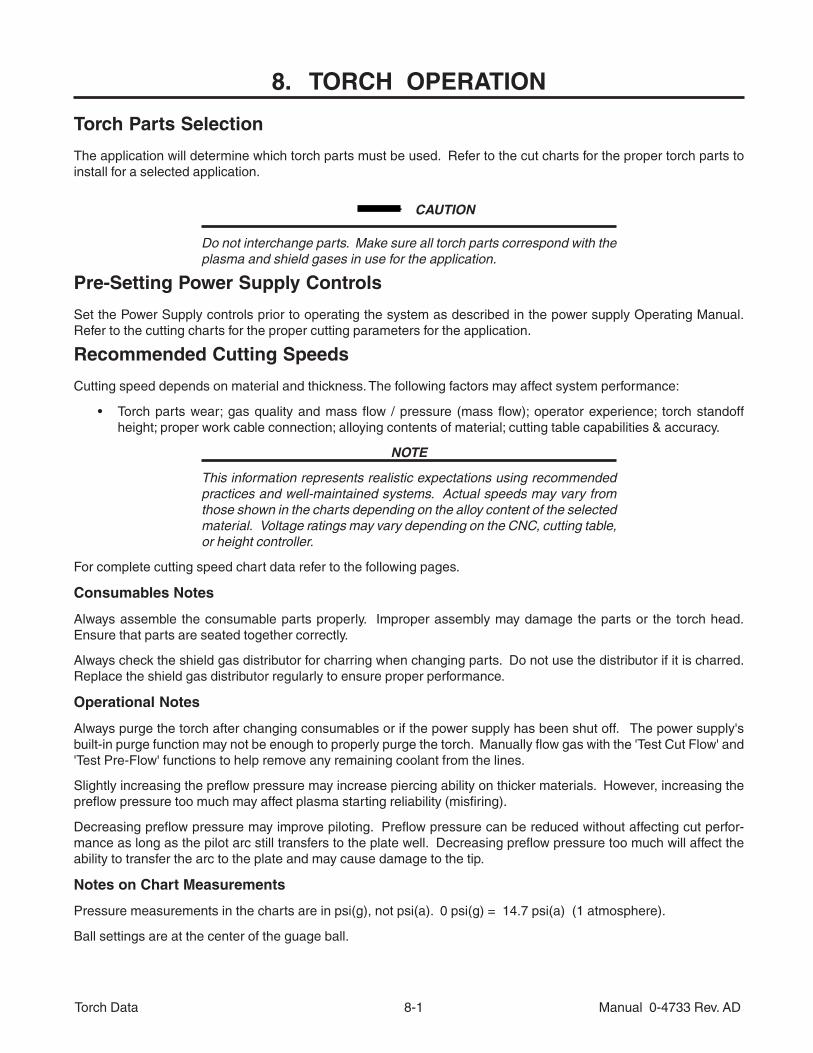
The application will determine which torch parts must be used. Refer to the cut charts for the proper torch parts toinstall for a selected application.
CAUTION
Do not interchange parts. Make sure all torch parts correspond with theplasma and shield gases in use for the application.
Pre-Setting Power Supply Controls
Set the Power Supply controls prior to operating the system as described in the power supply Operating Manual.Refer to the cutting charts for the proper cutting parameters for the application.
Recommended Cutting Speeds
Cutting speed depends on material and thickness. The following factors may affect system performance:
• Torch parts wear; gas quality and mass flow / pressure (mass flow); operator experience; torch standoffheight; proper work cable connection; alloying contents of material; cutting table capabilities & accuracy.
NOTE
This information represents realistic expectations using recommendedpractices and well-maintained systems. Actual speeds may vary fromthose shown in the charts depending on the alloy content of the selectedmaterial. Voltage ratings may vary depending on the CNC, cutting table,or height controller.
For complete cutting speed chart data refer to the following pages.
Consumables Notes
Always assemble the consumable parts properly. Improper assembly may damage the parts or the torch head.Ensure that parts are seated together correctly.
Always check the shield gas distributor for charring when changing parts. Do not use the distributor if it is charred.Replace the shield gas distributor regularly to ensure proper performance.
Operational Notes
Always purge the torch after changing consumables or if the power supply has been shut off. The power supply'sbuilt-in purge function may not be enough to properly purge the torch. Manually flow gas with the 'Test Cut Flow' and'Test Pre-Flow' functions to help remove any remaining coolant from the lines.
Slightly increasing the preflow pressure may increase piercing ability on thicker materials. However, increasing thepreflow pressure too much may affect plasma starting reliability (misfiring).
Decreasing preflow pressure may improve piloting. Preflow pressure can be reduced without affecting cut perfor-mance as long as the pilot arc still transfers to the plate well. Decreasing preflow pressure too much will affect theability to transfer the arc to the plate and may cause damage to the tip.
Notes on Chart Measurements
Pressure measurements in the charts are in psi(g), not psi(a). 0 psi(g) = 14.7 psi(a) (1 atmosphere).
Ball settings are at the center of the guage ball.
Torch Data 8-2 Manual 0-4733 Rev. AD
Ohmic Sensing
Ohmic sensing is not recommended with water shield. Water on the plate interferes electrically with the ohmicsensing circuit.
Direction of Cut
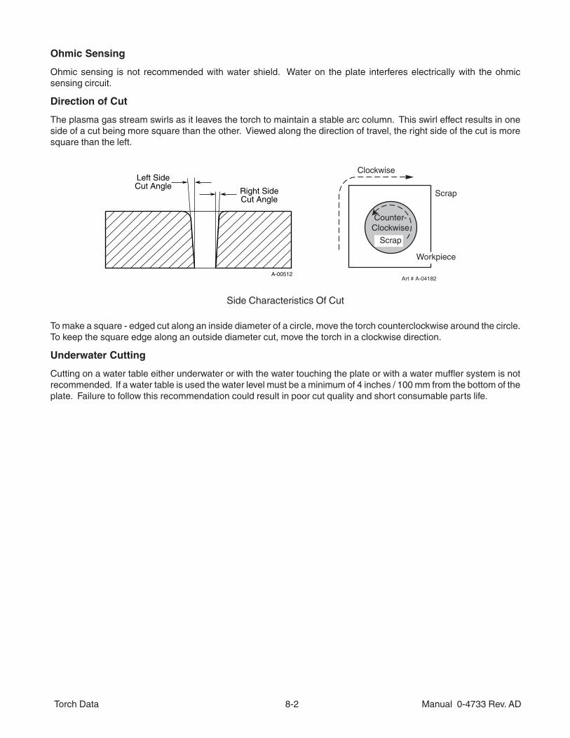
The plasma gas stream swirls as it leaves the torch to maintain a stable arc column. This swirl effect results in oneside of a cut being more square than the other. Viewed along the direction of travel, the right side of the cut is moresquare than the left.
Right SideCut Angle
Left SideCut Angle
A-00512
Scrap
Clockwise
Counter-Clockwise
Art # A-04182
Workpiece
Scrap
Side Characteristics Of Cut
To make a square - edged cut along an inside diameter of a circle, move the torch counterclockwise around the circle.To keep the square edge along an outside diameter cut, move the torch in a clockwise direction.
Underwater Cutting
Cutting on a water table either underwater or with the water touching the plate or with a water muffler system is notrecommended. If a water table is used the water level must be a minimum of 4 inches / 100 mm from the bottom of theplate. Failure to follow this recommendation could result in poor cut quality and short consumable parts life.
Torch Data 8-3 Manual 0-4733 Rev. AD
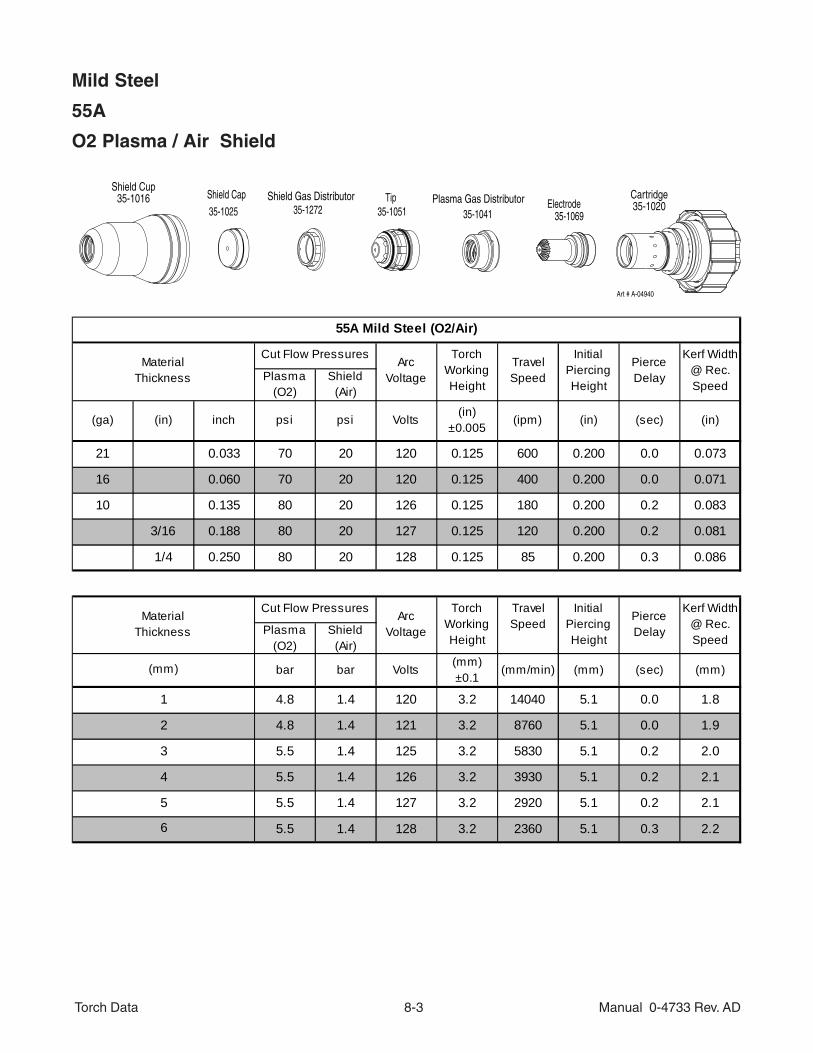
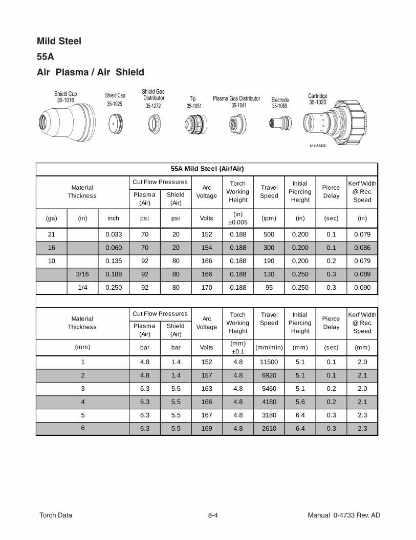
Mild Steel
55A
O2 Plasma / Air Shield
Plasma (O2)
Shield (Air)
(ga) (in) inch psi psi Volts(in)
±0.005(ipm) (in) (sec) (in)
21 0.033 70 20 120 0.125 600 0.200 0.0 0.073
16 0.060 70 20 120 0.125 400 0.200 0.0 0.071
10 0.135 80 20 126 0.125 180 0.200 0.2 0.083
3/16 0.188 80 20 127 0.125 120 0.200 0.2 0.081
1/4 0.250 80 20 128 0.125 85 0.200 0.3 0.086
Plasma (O2)
Shield (Air)
bar bar Volts(mm)±0.1
(mm/min) (mm) (sec) (mm)
4.8 1.4 120 3.2 14040 5.1 0.0 1.8
4.8 1.4 121 3.2 8760 5.1 0.0 1.9
5.5 1.4 125 3.2 5830 5.1 0.2 2.0
5.5 1.4 126 3.2 3930 5.1 0.2 2.1
5.5 1.4 127 3.2 2920 5.1 0.2 2.1
5.5 1.4 128 3.2 2360 5.1 0.3 2.2
55A Mild Steel (O2/Air)
MaterialThickness
Cut Flow PressuresArc
Voltage
Torch Working Height
TravelSpeed
Initial Piercing Height
Pierce Delay
Kerf Width @ Rec. Speed
Pierce Delay
Kerf Width @ Rec. Speed
MaterialThickness
Cut Flow PressuresArc
Voltage
Torch Working Height
4
5
6
(mm)
1
2
3
TravelSpeed
Initial Piercing Height
Tip35-1272 Electrode
35-1025
Shield Cap
35-1051 35-1041 35-1069
Cartridge35-1020
Shield Cup35-1016 Plasma Gas DistributorShield Gas Distributor
Art # A-04940
Torch Data 8-4 Manual 0-4733 Rev. AD
Mild Steel
55A
Air Plasma / Air Shield
35-1272Electrode
Shield Cap35-1025
Tip35-1051 35-106935-1041
Cartridge35-1020
Shield Cup35-1016 Plasma Gas Distributor
Shield Gas Distributor
Art # A-04941
Plasma (Air)
Shield (Air)
(ga) (in) inch psi psi Volts(in)
±0.005(ipm) (in) (sec) (in)
21 0.033 70 20 152 0.188 500 0.200 0.1 0.079
16 0.060 70 20 154 0.188 300 0.200 0.1 0.086
10 0.135 92 80 166 0.188 190 0.200 0.2 0.079
3/16 0.188 92 80 166 0.188 130 0.250 0.3 0.089
1/4 0.250 92 80 170 0.188 95 0.250 0.3 0.090
Plasma (Air)
Shield (Air)
bar bar Volts(mm)±0.1
(mm/min) (mm) (sec) (mm)
4.8 1.4 152 4.8 11500 5.1 0.1 2.0
4.8 1.4 157 4.8 6920 5.1 0.1 2.1
6.3 5.5 163 4.8 5460 5.1 0.2 2.0
6.3 5.5 166 4.8 4180 5.6 0.2 2.1
6.3 5.5 167 4.8 3180 6.4 0.3 2.3
6.3 5.5 169 4.8 2610 6.4 0.3 2.3
55A Mild Steel (Air/Air)
MaterialThickness
Cut Flow PressuresArc
Voltage
Torch Working Height
TravelSpeed
Initial Piercing Height
Pierce Delay
Kerf Width @ Rec. Speed
Pierce Delay
Kerf Width @ Rec. Speed
MaterialThickness
Cut Flow PressuresArc
Voltage
Torch Working Height
4
5
6
(mm)
1
2
3
TravelSpeed
Initial Piercing Height
Torch Data 8-5 Manual 0-4733 Rev. AD
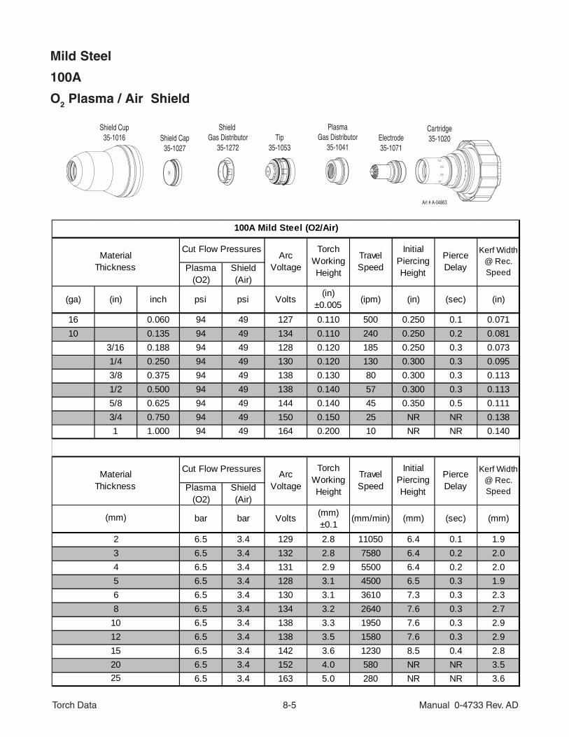
Mild Steel
100A
O2 Plasma / Air Shield
Plasma (O2)
Shield (Air)
(ga) (in) inch psi psi Volts(in)
±0.005 (ipm) (in) (sec) (in)
16 0.060 94 49 127 0.110 500 0.250 0.1 0.07110 0.135 94 49 134 0.110 240 0.250 0.2 0.081
3/16 0.188 94 49 128 0.120 185 0.250 0.3 0.0731/4 0.250 94 49 130 0.120 130 0.300 0.3 0.0953/8 0.375 94 49 138 0.130 80 0.300 0.3 0.1131/2 0.500 94 49 138 0.140 57 0.300 0.3 0.1135/8 0.625 94 49 144 0.140 45 0.350 0.5 0.1113/4 0.750 94 49 150 0.150 25 NR NR 0.1381 1.000 94 49 164 0.200 10 NR NR 0.140
Plasma (O2)
Shield (Air)
bar bar Volts (mm)±0.1
(mm/min) (mm) (sec) (mm)
6.5 3.4 129 2.8 11050 6.4 0.1 1.96.5 3.4 132 2.8 7580 6.4 0.2 2.06.5 3.4 131 2.9 5500 6.4 0.2 2.06.5 3.4 128 3.1 4500 6.5 0.3 1.96.5 3.4 130 3.1 3610 7.3 0.3 2.36.5 3.4 134 3.2 2640 7.6 0.3 2.76.5 3.4 138 3.3 1950 7.6 0.3 2.96.5 3.4 138 3.5 1580 7.6 0.3 2.96.5 3.4 142 3.6 1230 8.5 0.4 2.86.5 3.4 152 4.0 580 NR NR 3.56.5 3.4 163 5.0 280 NR NR 3.6
100A Mild Steel (O2/Air)
MaterialThickness
Cut Flow PressuresArc
Voltage
Torch Working Height
TravelSpeed
Initial Piercing Height
Pierce Delay
Kerf Width @ Rec. Speed
Pierce Delay
Kerf Width @ Rec. Speed
MaterialThickness
Cut Flow Pressures Arc Voltage
Torch Working Height
25
568
10121520
(mm)
234
TravelSpeed
Initial Piercing Height
Cartridge35-1020
Shield Cup35-1016 Shield Cap
35-1027
Shield Gas Distributor
35-1272Tip
35-1053
PlasmaGas Distributor
35-1041Electrode35-1071
Art # A-04863
Torch Data 8-6 Manual 0-4733 Rev. AD
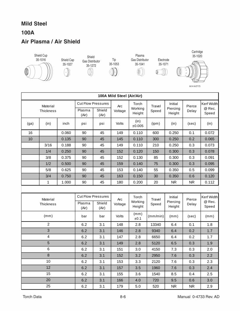
Mild Steel
100A
Air Plasma / Air Shield
Plasma (Air)
Shield (Air)
(ga) (in) inch psi psi Volts(in)
±0.005(ipm) (in) (sec) (in)
16 0.060 90 45 149 0.110 600 0.250 0.1 0.07210 0.135 90 45 145 0.110 300 0.250 0.2 0.065
3/16 0.188 90 45 149 0.110 210 0.250 0.3 0.0731/4 0.250 90 45 152 0.120 150 0.300 0.3 0.0783/8 0.375 90 45 152 0.130 85 0.300 0.3 0.0911/2 0.500 90 45 159 0.140 75 0.300 0.3 0.0955/8 0.625 90 45 153 0.140 55 0.350 0.5 0.0993/4 0.750 90 45 163 0.150 30 0.350 0.6 0.1201 1.000 90 45 180 0.200 20 NR NR 0.112
Plasma (Air)
Shield (Air)
bar bar Volts(mm)±0.1
(mm/min) (mm) (sec) (mm)
6.2 3.1 148 2.8 13340 6.4 0.1 1.86.2 3.1 146 2.8 9340 6.4 0.2 1.76.2 3.1 147 2.8 6650 6.4 0.2 1.76.2 3.1 149 2.8 5120 6.5 0.3 1.96.2 3.1 151 3.0 4150 7.3 0.3 2.06.2 3.1 152 3.2 2950 7.6 0.3 2.26.2 3.1 153 3.3 2120 7.6 0.3 2.36.2 3.1 157 3.5 1960 7.6 0.3 2.46.2 3.1 155 3.6 1540 8.5 0.4 2.56.2 3.1 166 4.0 720 9.5 0.6 3.06.2 3.1 179 5.0 520 NR NR 2.9
(mm)
234
25
568
10121520
Pierce Delay
Arc Voltage
Torch Working Height
TravelSpeed
Initial Piercing Height
MaterialThickness
Cut Flow Pressures
Kerf Width @ Rec. Speed
Pierce Delay
Kerf Width @ Rec. Speed
100A Mild Steel (Air/Air)
MaterialThickness
Cut Flow PressuresArc
Voltage
Torch Working Height
TravelSpeed
Initial Piercing Height
Cartridge35-1020Shield Cup
35-1016 Shield Cap35-1027
Shield Gas Distributor
35-1272
Tip35-1053
PlasmaGas Distributor
35-1041Electrode35-1071
Art # A-07173
Torch Data 8-7 Manual 0-4733 Rev. AD
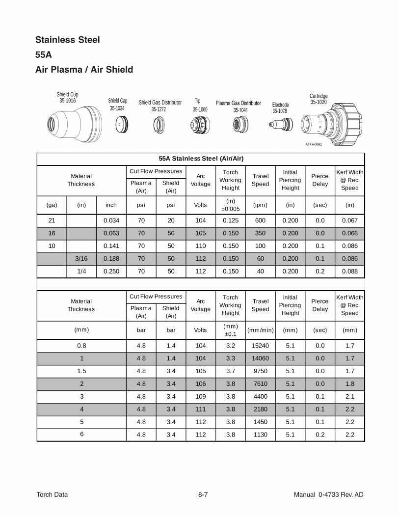
Tip35-1272
ElectrodeShield Cap35-1034 35-1060 35-107835-1041
Cartridge35-1020
Shield Cup35-1016 Plasma Gas DistributorShield Gas Distributor
Art # A-04942
Stainless Steel
55A
Air Plasma / Air Shield
Plasma (Air)
Shield (Air)
(ga) (in) inch psi psi Volts(in)
±0.005(ipm) (in) (sec) (in)
21 0.034 70 20 104 0.125 600 0.200 0.0 0.067
16 0.063 70 50 105 0.150 350 0.200 0.0 0.068
10 0.141 70 50 110 0.150 100 0.200 0.1 0.086
3/16 0.188 70 50 112 0.150 60 0.200 0.1 0.086
1/4 0.250 70 50 112 0.150 40 0.200 0.2 0.088
Plasma (Air)
Shield (Air)
bar bar Volts (mm)±0.1
(mm/min) (mm) (sec) (mm)
4.8 1.4 104 3.2 15240 5.1 0.0 1.7
4.8 1.4 104 3.3 14060 5.1 0.0 1.7
4.8 3.4 105 3.7 9750 5.1 0.0 1.7
4.8 3.4 106 3.8 7610 5.1 0.0 1.8
4.8 3.4 109 3.8 4400 5.1 0.1 2.1
4.8 3.4 111 3.8 2180 5.1 0.1 2.2
4.8 3.4 112 3.8 1450 5.1 0.1 2.2
4.8 3.4 112 3.8 1130 5.1 0.2 2.2
55A Stainless Steel (Air/Air)
MaterialThickness
Cut Flow PressuresArc
Voltage
Torch Working Height
TravelSpeed
Initial Piercing Height
Pierce Delay
Kerf Width @ Rec. Speed
MaterialThickness
Cut Flow PressuresArc
Voltage
Torch Working Height
TravelSpeed
Initial Piercing Height
Pierce Delay
Kerf Width @ Rec. Speed
6
2
3
4
5
(mm)
0.8
1
1.5
Torch Data 8-8 Manual 0-4733 Rev. AD
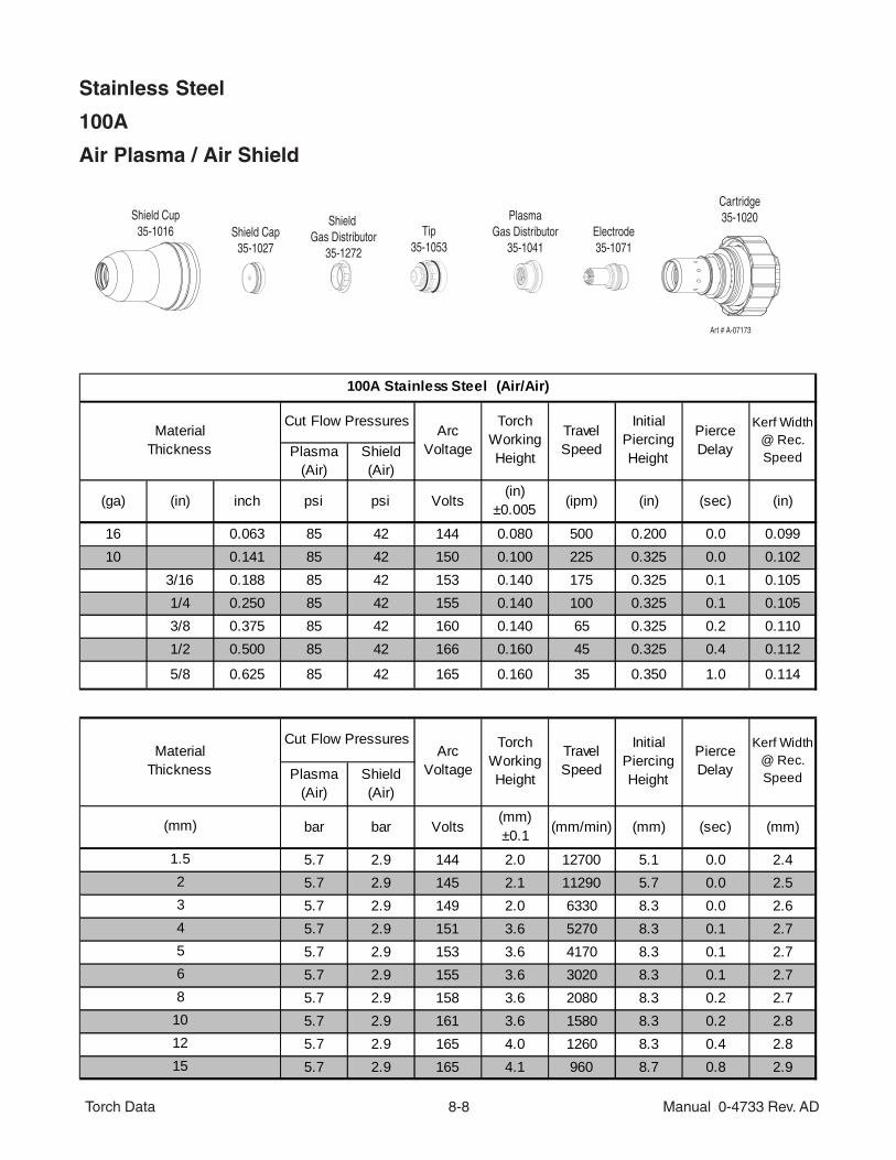
Stainless Steel
100A
Air Plasma / Air Shield
Plasma (Air)
Shield (Air)
(ga) (in) inch psi psi Volts(in)
±0.005 (ipm) (in) (sec) (in)
16 0.063 85 42 144 0.080 500 0.200 0.0 0.09910 0.141 85 42 150 0.100 225 0.325 0.0 0.102
3/16 0.188 85 42 153 0.140 175 0.325 0.1 0.1051/4 0.250 85 42 155 0.140 100 0.325 0.1 0.1053/8 0.375 85 42 160 0.140 65 0.325 0.2 0.1101/2 0.500 85 42 166 0.160 45 0.325 0.4 0.112
5/8 0.625 85 42 165 0.160 35 0.350 1.0 0.114
Plasma (Air)
Shield (Air)
bar bar Volts(mm)±0.1 (mm/min) (mm) (sec) (mm)
5.7 2.9 144 2.0 12700 5.1 0.0 2.45.7 2.9 145 2.1 11290 5.7 0.0 2.55.7 2.9 149 2.0 6330 8.3 0.0 2.65.7 2.9 151 3.6 5270 8.3 0.1 2.75.7 2.9 153 3.6 4170 8.3 0.1 2.75.7 2.9 155 3.6 3020 8.3 0.1 2.75.7 2.9 158 3.6 2080 8.3 0.2 2.75.7 2.9 161 3.6 1580 8.3 0.2 2.85.7 2.9 165 4.0 1260 8.3 0.4 2.85.7 2.9 165 4.1 960 8.7 0.8 2.9
100A Stainless Steel (Air/Air)
MaterialThickness
Cut Flow PressuresArc
Voltage
Torch Working Height
TravelSpeed
Initial Piercing Height
Pierce Delay
Kerf Width @ Rec. Speed
TravelSpeed
Initial Piercing Height
Pierce Delay
Kerf Width @ Rec. Speed
MaterialThickness
Cut Flow PressuresArc
Voltage
Torch Working Height
(mm)
1.523
101215
4568
Cartridge35-1020Shield Cup
35-1016 Shield Cap35-1027
Shield Gas Distributor
35-1272
Tip35-1053
PlasmaGas Distributor
35-1041Electrode35-1071
Art # A-07173
Torch Data 8-9 Manual 0-4733 Rev. AD
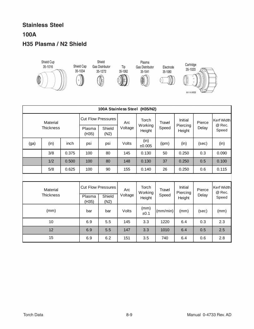
Stainless Steel
100A
H35 Plasma / N2 Shield
Plasma (H35)
Shield (N2)
(ga) (in) inch psi psi Volts(in)
±0.005 (ipm) (in) (sec) (in)
3/8 0.375 100 80 145 0.130 50 0.250 0.3 0.090
1/2 0.500 100 80 148 0.130 37 0.250 0.5 0.100
5/8 0.625 100 90 155 0.140 26 0.250 0.6 0.115
Plasma (H35)
Shield (N2)
bar bar Volts(mm)±0.1 (mm/min) (mm) (sec) (mm)
6.9 5.5 145 3.3 1220 6.4 0.3 2.3
6.9 5.5 147 3.3 1010 6.4 0.5 2.5
6.9 6.2 151 3.5 740 6.4 0.6 2.8
100A Stainless Steel (H35/N2)
MaterialThickness
Cut Flow PressuresArc
Voltage
Torch Working Height
TravelSpeed
Initial Piercing Height
Pierce Delay
Kerf Width @ Rec. Speed
TravelSpeed
Initial Piercing Height
Pierce Delay
Kerf Width @ Rec. Speed
MaterialThickness
Cut Flow Pressures Arc Voltage
Torch Working Height
(mm)
10
12
15
Tip35-1062
Electrode35-1080
PlasmaGas Distributor
35-1041
Art # A-04938
Cartridge35-1020
Shield Cup35-1016 Shield Cap
35-1034
Shield Gas Distributor
35-1272
Torch Data 8-10 Manual 0-4733 Rev. AD
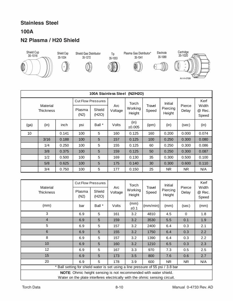
Stainless Steel
100A
N2 Plasma / H20 Shield
Plasma (N2)
Shield (H2O)
(ga) (in) inch psi Ball * Volts(in)
±0.005 (ipm) (in) (sec) (in)
10 0.141 100 5 160 0.125 160 0.200 0.000 0.0743/16 0.188 100 5 157 0.125 100 0.250 0.300 0.0801/4 0.250 100 5 155 0.125 60 0.250 0.300 0.0863/8 0.375 100 5 159 0.125 50 0.250 0.300 0.0871/2 0.500 100 5 169 0.130 35 0.300 0.500 0.1005/8 0.625 100 5 175 0.140 30 0.300 0.600 0.1103/4 0.750 100 5 177 0.150 25 NR NR N/A
Plasma (N2)
Shield (H2O)
bar Ball * Volts (mm)±0.1
(mm/min) (mm) (sec) (mm)
6.9 5 161 3.2 4810 4.5 0 1.86.9 5 159 3.2 3530 5.5 0.1 1.96.9 5 157 3.2 2400 6.4 0.3 2.16.9 5 155 3.2 1750 6.4 0.3 2.26.9 5 157 3.2 1390 6.4 0.3 2.26.9 5 160 3.2 1210 6.5 0.3 2.36.9 5 167 3.3 970 7.3 0.5 2.56.9 5 173 3.5 800 7.6 0.6 2.76.9 5 178 3.9 600 NR NR N/A
NOTE: Ohmic height sensing is not recommended with water shield. Water on the plate interferes electrically with the ohmic sensing circuit.
100A Stainless Steel (N2/H2O)
MaterialThickness
Cut Flow PressuresArc
Voltage
Torch Working Height
TravelSpeed
Initial Piercing Height
Pierce Delay
Kerf Width
@ Rec. Speed
Pierce Delay
Kerf Width
@ Rec. Speed
MaterialThickness
Cut Flow PressuresArc
Voltage
Torch Working Height
45
TravelSpeed
Initial Piercing Height
* Ball setting for shield water is set using a line pressure of 55 psi / 3.8 bar
1520
68
1012
(mm)
3
35-1053 35-1041 35-1089Cartridge35-1020
Shield Cup35-1016
Plasma Gas Distributor*Shield Gas DistributorShield Cap
Art # A-07089
35-1034 35-1272Tip Electrode
Torch Data 8-11 Manual 0-4733 Rev. AD
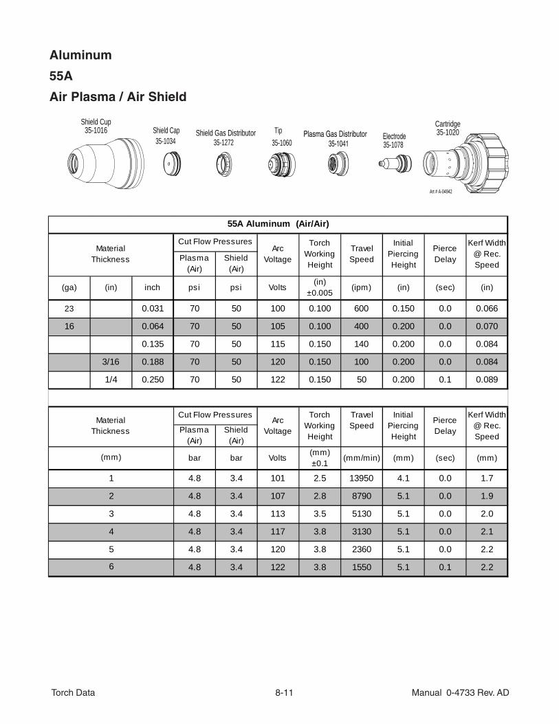
Aluminum
55A
Air Plasma / Air Shield
Tip35-1272
ElectrodeShield Cap35-1034 35-1060 35-107835-1041
Cartridge35-1020
Shield Cup35-1016 Plasma Gas DistributorShield Gas Distributor
Art # A-04942
Plasma (Air)
Shield (Air)
(ga) (in) inch psi psi Volts(in)
±0.005(ipm) (in) (sec) (in)
23 0.031 70 50 100 0.100 600 0.150 0.0 0.066
16 0.064 70 50 105 0.100 400 0.200 0.0 0.070
0.135 70 50 115 0.150 140 0.200 0.0 0.084
3/16 0.188 70 50 120 0.150 100 0.200 0.0 0.084
1/4 0.250 70 50 122 0.150 50 0.200 0.1 0.089
Plasma (Air)
Shield (Air)
bar bar Volts(mm)±0.1
(mm/min) (mm) (sec) (mm)
4.8 3.4 101 2.5 13950 4.1 0.0 1.7
4.8 3.4 107 2.8 8790 5.1 0.0 1.9
4.8 3.4 113 3.5 5130 5.1 0.0 2.0
4.8 3.4 117 3.8 3130 5.1 0.0 2.1
4.8 3.4 120 3.8 2360 5.1 0.0 2.2
4.8 3.4 122 3.8 1550 5.1 0.1 2.2
55A Aluminum (Air/Air)
MaterialThickness
Cut Flow PressuresArc
Voltage
Torch Working Height
TravelSpeed
Initial Piercing Height
Pierce Delay
Kerf Width @ Rec. Speed
Pierce Delay
Kerf Width @ Rec. Speed
MaterialThickness
Cut Flow PressuresArc
Voltage
Torch Working Height
4
5
6
(mm)
1
2
3
TravelSpeed
Initial Piercing Height
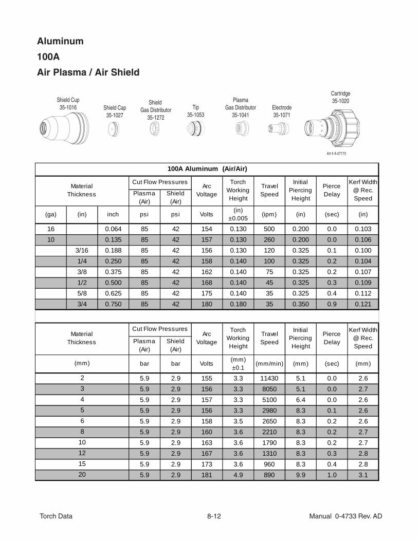
Torch Data 8-12 Manual 0-4733 Rev. AD
Aluminum
100A
Air Plasma / Air Shield
Plasma (Air)
Shield (Air)
(ga) (in) inch psi psi Volts(in)
±0.005 (ipm) (in) (sec) (in)
16 0.064 85 42 154 0.130 500 0.200 0.0 0.10310 0.135 85 42 157 0.130 260 0.200 0.0 0.106
3/16 0.188 85 42 156 0.130 120 0.325 0.1 0.1001/4 0.250 85 42 158 0.140 100 0.325 0.2 0.1043/8 0.375 85 42 162 0.140 75 0.325 0.2 0.1071/2 0.500 85 42 168 0.140 45 0.325 0.3 0.1095/8 0.625 85 42 175 0.140 35 0.325 0.4 0.1123/4 0.750 85 42 180 0.180 35 0.350 0.9 0.121
Plasma (Air)
Shield (Air)
bar bar Volts(mm)±0.1
(mm/min) (mm) (sec) (mm)
5.9 2.9 155 3.3 11430 5.1 0.0 2.65.9 2.9 156 3.3 8050 5.1 0.0 2.75.9 2.9 157 3.3 5100 6.4 0.0 2.65.9 2.9 156 3.3 2980 8.3 0.1 2.65.9 2.9 158 3.5 2650 8.3 0.2 2.65.9 2.9 160 3.6 2210 8.3 0.2 2.75.9 2.9 163 3.6 1790 8.3 0.2 2.75.9 2.9 167 3.6 1310 8.3 0.3 2.85.9 2.9 173 3.6 960 8.3 0.4 2.85.9 2.9 181 4.9 890 9.9 1.0 3.1
121520
568
10
(mm)
234
TravelSpeed
Initial Piercing Height
Pierce Delay
Kerf Width @ Rec. Speed
MaterialThickness
Cut Flow PressuresArc
Voltage
Torch Working Height
100A Aluminum (Air/Air)
MaterialThickness
Cut Flow PressuresArc
Voltage
Torch Working Height
TravelSpeed
Initial Piercing Height
Pierce Delay
Kerf Width @ Rec. Speed
Cartridge35-1020Shield Cup
35-1016 Shield Cap35-1027
Shield Gas Distributor
35-1272
Tip35-1053
PlasmaGas Distributor
35-1041Electrode35-1071
Art # A-07173
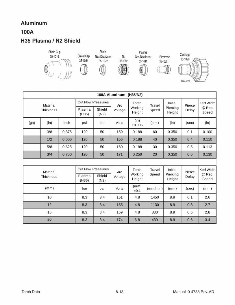
Torch Data 8-13 Manual 0-4733 Rev. AD
Aluminum
100A
H35 Plasma / N2 Shield
Plasma (H35)
Shield (N2)
(ga) (in) inch psi psi Volts(in)
±0.005(ipm) (in) (sec) (in)
3/8 0.375 120 50 150 0.188 60 0.350 0.1 0.100
1/2 0.500 120 50 156 0.188 40 0.350 0.4 0.110
5/8 0.625 120 50 160 0.188 30 0.350 0.5 0.113
3/4 0.750 120 50 171 0.250 20 0.350 0.6 0.130
Plasma (H35)
Shield (N2)
bar bar Volts(mm)±0.1
(mm/min) (mm) (sec) (mm)
8.3 3.4 151 4.8 1450 8.9 0.1 2.6
8.3 3.4 155 4.8 1130 8.9 0.3 2.7
8.3 3.4 159 4.8 830 8.9 0.5 2.8
8.3 3.4 174 6.8 430 8.9 0.6 3.4
100A Aluminum (H35/N2)
MaterialThickness
Cut Flow PressuresArc
Voltage
Torch Working Height
TravelSpeed
Initial Piercing Height
Pierce Delay
Kerf Width @ Rec. Speed
MaterialThickness
Cut Flow PressuresArc
Voltage
Torch Working Height
20
(mm)
10
12
15
TravelSpeed
Initial Piercing Height
Pierce Delay
Kerf Width @ Rec. Speed
Tip35-1062
Electrode35-1080
PlasmaGas Distributor
35-1041
Art # A-04938
Cartridge35-1020
Shield Cup35-1016 Shield Cap
35-1034
Shield Gas Distributor
35-1272

Torch Data 8-14 Manual 0-4733 Rev. AD
Aluminum
100A
N2 Plasma / H20 Shield
Plasma (N2)
Shield (H2O)
(ga) (in) inch psi Ball * Volts (in)±0.005
(ipm) (in) (sec) (in)
10 0.135 100 5 148 0.125 170 0.200 0.0 0.072
3/16 0.188 100 5 158 0.125 80 0.250 0.3 0.080
1/4 0.250 100 5 158 0.125 60 0.250 0.3 0.085
3/8 0.375 100 5 161 0.125 50 0.250 0.3 0.086
1/2 0.500 100 5 170 0.130 35 0.300 0.6 0.091
5/8 0.625 100 5 180 0.140 20 0.300 0.8 0.120
Plasma (N2)
Shield (H2O)
bar Ball * Volts (mm)±0.1
(mm/min) (mm) (sec) (mm)
6.9 5 152 3.2 3350 5.6 0.1 1.9
6.9 5 158 3.2 1960 6.4 0.3 2.1
6.9 5 158 3.2 1640 6.4 0.3 2.1
6.9 5 160 3.2 1390 6.4 0.3 2.2
6.9 5 162 3.2 1210 6.5 0.3 2.2
6.9 5 168 3.3 970 7.3 0.5 2.3
6.9 5 177 3.5 610 7.6 0.7 2.8
NOTE: Ohmic height sensing is not recommended with water shield.Water on the plate interferes electrically with the ohmic sensing circuit.
* Ball setting for shield water is set using a line pressure of 55 psi / 3.8 bar.
8
10
12
15
(mm)
4
5
6
MaterialThickness
Cut Flow PressuresArc
Voltage
Torch Working Height
TravelSpeed
Initial Piercing Height
Pierce Delay
Kerf Width
@ Rec. Speed
100A Aluminum (N2/H2O)
MaterialThickness
Cut Flow PressuresArc
Voltage
Torch Working Height
TravelSpeed
Initial Piercing Height
Pierce Delay
Kerf Width
@ Rec. Speed
Cartridge35-1020Shield Cup
35-1016 Shield Cap35-1034
Shield Gas Distributor
35-1272
Tip35-1053
PlasmaGas Distributor
35-1041
Electrode35-1089
Art # A-07174

Torch Data 8-15 Manual 0-4733 Rev. AD
TORCH REPLACEMENT PARTS
Returns
If a product must be returned for service, contact your authorized distributor. Materials returned without proper autho-rization will not be accepted.
Ordering Information
Order replacement parts by catalog number and complete description of the part or assembly. Also include themodel and serial number of the machine or torch.
Refer to parts diagrams within the body of the manual for consumable parts and replacement O-Ring catalog num-bers.
Qty. Description Catalog Number
1 XT-301 Torch w/ 25' / 7.6 m Leads 2-7000
1 XT-301 Torch w/ 35' / 10.6 m Leads 2-7001
1 XT-301 Torch w/ 50' / 15.2 mLeads 2-7002
1 XT-301 Torch w/ 75' / 22.9 m Leads 2-7003
1 XT-301 Torch w/ 100' / 30.5 m Leads 2-7004
1 O-Ring Lubricant (Christo-Lube MCG-129) 9-4893
1 Coolant Check Valve Kit 9-4846
1 Water Shield Regulator 8-6118
1 Torch Cartridge (includes Cartridge Tool) 35-1020
1 Cartridge Tool 9-9431
1 Shield Cup 35-1016
O-Ring, Cat. No. 8-0544
Inner O-Ring (Cat. No. 8-0545) Location (Under Locking Ring)
O-Ring, Cat. No. 8-0540
Snap Ring
Cartridge Assembly
Art # A-07087
Cartridge Retaining Ring 9-9489
O-Rings
Art # A-07088
Cat. No. 8-0539
Cat. No. 8-3487
Cat. No. 8-0530
Torch Head
Cat. No. 9-9041
Coolant Tube Kit9-9429
Torch Data 8-16 Manual 0-4733 Rev. AD
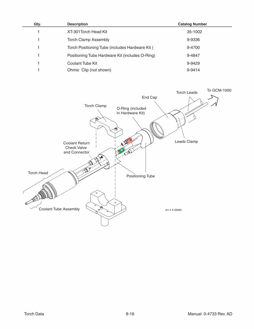
Qty. Description Catalog Number
1 XT-301Torch Head Kit 35-1002
1 Torch Clamp Assembly 9-9336
1 Torch Positioning Tube (includes Hardware Kit ) 9-4700
1 Positioning Tube Hardware Kit (includes O-Ring) 9-4847
1 Coolant Tube Kit 9-9429
1 Ohmic Clip (not shown) 9-9414
Art # A-06980
Torch Clamp
Coolant ReturnCheck Valve
and ConnectorG
Positioning Tube
R
End Cap
O-Ring (included in Hardware Kit)
To GCM-1000Torch Leads
Leads Clamp
Torch Head
Coolant Tube Assembly
Torch Data 8-17 Manual 0-4733 Rev. AD
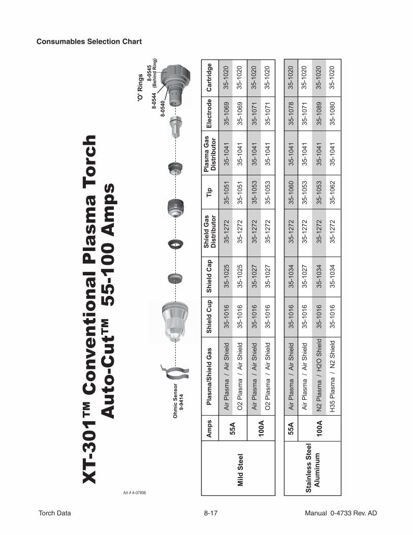
Consumables Selection Chart
XT-
301™
Con
vent
iona
l Pla
sma
Torc
h
A
uto-
Cut
™ 5
5-10
0 A
mps
100A
55A
Air
Pla
sma
/ A
ir S
hiel
d
N2
Pla
sma
/ H
2O S
hiel
d
Air
Pla
sma
/ A
ir S
hiel
d
H35
Pla
sma
/ N
2 S
hiel
d
35-1
041
35-1
272
35-1
034
35-1
016
35-1
078
35-1
020
35-1
060
35-1
041
35-1
272
35-1
034
35-1
016
35-1
089
35-1
020
35-1
053
35-1
041
35-1
272
35-1
027
35-1
016
35-1
071
35-1
020
35-1
053
35-1
041
35-1
272
35-1
034
35-1
016
35-1
080
35-1
020
35-1
062
Stai
nles
s St
eel
A
lum
inum
Mild
Ste
el
Plas
ma/
Shie
ld G
asA
mps
Dis
trib
utor
Plas
ma
Gas
Shie
ld G
asD
istr
ibut
orSh
ield
Cap
Shie
ld C
upEl
ectr
ode
Tip
100A
Car
trid
ge
Air
Pla
sma
/ A
ir S
hiel
d
Air
Pla
sma
/ A
ir S
hiel
d
55A
O2
Pla
sma
/ A
ir S
hiel
d
O2
Pla
sma
/ A
ir S
hiel
d
35-1
041
35-1
272
35-1
025
35-1
016
35-1
069
35-1
020
35-1
051
35-1
041
35-1
272
35-1
027
35-1
016
35-1
071
35-1
053
35-1
041
35-1
272
35-1
025
35-1
016
35-1
069
35-1
020
35-1
051
35-1
041
35-1
272
35-1
027
35-1
016
35-1
071
35-1
020
35-1
053
35-1
020
9-94
14O
hmic
Sen
sor
'O' R
ings
8-05
408-05
44(B
ehin
d Ri
ng)
8-05
45
Art # A-07806
Torch Data 8-18 Manual 0-4733 Rev. AD
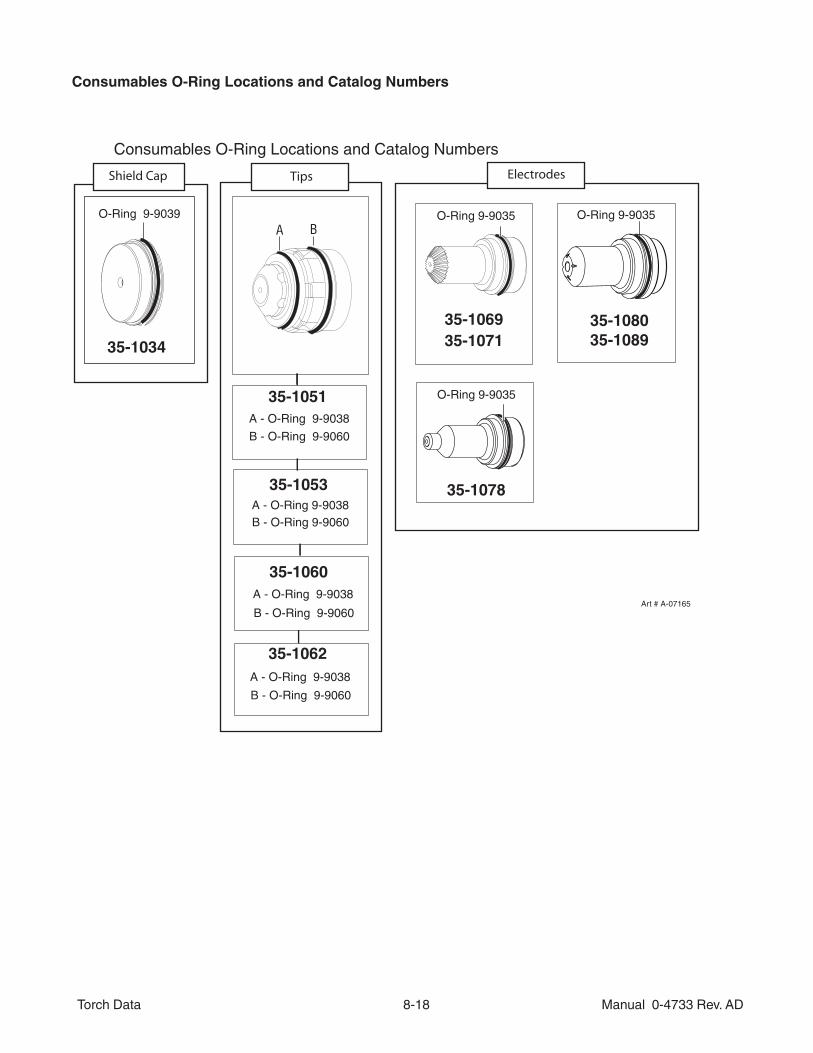
Consumables O-Ring Locations and Catalog Numbers
Art # A-07165
35-1034
35-1051
35-1060
35-1069
35-1078
O-Ring 9-9035
O-Ring 9-9035
35-1053
35-1062
35-1071
O-Ring 9-9039
B - O-Ring 9-9060
A - O-Ring 9-9038
A - O-Ring 9-9038
B - O-Ring 9-9060
B - O-Ring 9-9060A - O-Ring 9-9038
B - O-Ring 9-9060
A - O-Ring 9-9038
Consumables O-Ring Locations and Catalog Numbers
Shield Cap ElectrodesTips
35-1080
O-Ring 9-9035A B
35-1089
Torch Data 8-19 Manual 0-4733 Rev. AD
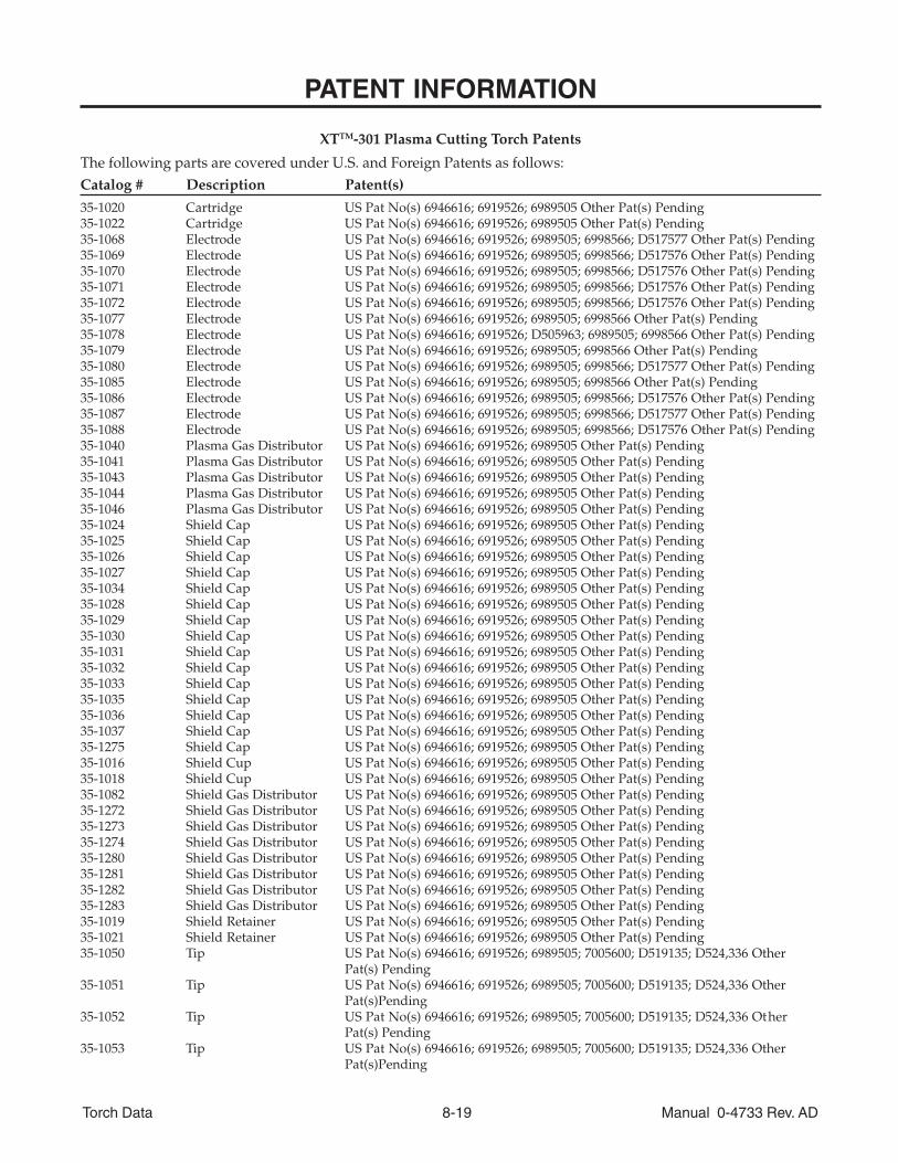
PATENT INFORMATION
XTTM-301 Plasma Cutting Torch Patents
The following parts are covered under U.S. and Foreign Patents as follows:Catalog # Description Patent(s)
35-1020 Cartridge US Pat No(s) 6946616; 6919526; 6989505 Other Pat(s) Pending35-1022 Cartridge US Pat No(s) 6946616; 6919526; 6989505 Other Pat(s) Pending35-1068 Electrode US Pat No(s) 6946616; 6919526; 6989505; 6998566; D517577 Other Pat(s) Pending35-1069 Electrode US Pat No(s) 6946616; 6919526; 6989505; 6998566; D517576 Other Pat(s) Pending35-1070 Electrode US Pat No(s) 6946616; 6919526; 6989505; 6998566; D517576 Other Pat(s) Pending35-1071 Electrode US Pat No(s) 6946616; 6919526; 6989505; 6998566; D517576 Other Pat(s) Pending35-1072 Electrode US Pat No(s) 6946616; 6919526; 6989505; 6998566; D517576 Other Pat(s) Pending35-1077 Electrode US Pat No(s) 6946616; 6919526; 6989505; 6998566 Other Pat(s) Pending35-1078 Electrode US Pat No(s) 6946616; 6919526; D505963; 6989505; 6998566 Other Pat(s) Pending35-1079 Electrode US Pat No(s) 6946616; 6919526; 6989505; 6998566 Other Pat(s) Pending35-1080 Electrode US Pat No(s) 6946616; 6919526; 6989505; 6998566; D517577 Other Pat(s) Pending35-1085 Electrode US Pat No(s) 6946616; 6919526; 6989505; 6998566 Other Pat(s) Pending35-1086 Electrode US Pat No(s) 6946616; 6919526; 6989505; 6998566; D517576 Other Pat(s) Pending35-1087 Electrode US Pat No(s) 6946616; 6919526; 6989505; 6998566; D517577 Other Pat(s) Pending35-1088 Electrode US Pat No(s) 6946616; 6919526; 6989505; 6998566; D517576 Other Pat(s) Pending35-1040 Plasma Gas Distributor US Pat No(s) 6946616; 6919526; 6989505 Other Pat(s) Pending35-1041 Plasma Gas Distributor US Pat No(s) 6946616; 6919526; 6989505 Other Pat(s) Pending35-1043 Plasma Gas Distributor US Pat No(s) 6946616; 6919526; 6989505 Other Pat(s) Pending35-1044 Plasma Gas Distributor US Pat No(s) 6946616; 6919526; 6989505 Other Pat(s) Pending35-1046 Plasma Gas Distributor US Pat No(s) 6946616; 6919526; 6989505 Other Pat(s) Pending35-1024 Shield Cap US Pat No(s) 6946616; 6919526; 6989505 Other Pat(s) Pending35-1025 Shield Cap US Pat No(s) 6946616; 6919526; 6989505 Other Pat(s) Pending35-1026 Shield Cap US Pat No(s) 6946616; 6919526; 6989505 Other Pat(s) Pending35-1027 Shield Cap US Pat No(s) 6946616; 6919526; 6989505 Other Pat(s) Pending35-1034 Shield Cap US Pat No(s) 6946616; 6919526; 6989505 Other Pat(s) Pending35-1028 Shield Cap US Pat No(s) 6946616; 6919526; 6989505 Other Pat(s) Pending35-1029 Shield Cap US Pat No(s) 6946616; 6919526; 6989505 Other Pat(s) Pending35-1030 Shield Cap US Pat No(s) 6946616; 6919526; 6989505 Other Pat(s) Pending35-1031 Shield Cap US Pat No(s) 6946616; 6919526; 6989505 Other Pat(s) Pending35-1032 Shield Cap US Pat No(s) 6946616; 6919526; 6989505 Other Pat(s) Pending35-1033 Shield Cap US Pat No(s) 6946616; 6919526; 6989505 Other Pat(s) Pending35-1035 Shield Cap US Pat No(s) 6946616; 6919526; 6989505 Other Pat(s) Pending35-1036 Shield Cap US Pat No(s) 6946616; 6919526; 6989505 Other Pat(s) Pending35-1037 Shield Cap US Pat No(s) 6946616; 6919526; 6989505 Other Pat(s) Pending35-1275 Shield Cap US Pat No(s) 6946616; 6919526; 6989505 Other Pat(s) Pending35-1016 Shield Cup US Pat No(s) 6946616; 6919526; 6989505 Other Pat(s) Pending35-1018 Shield Cup US Pat No(s) 6946616; 6919526; 6989505 Other Pat(s) Pending35-1082 Shield Gas Distributor US Pat No(s) 6946616; 6919526; 6989505 Other Pat(s) Pending35-1272 Shield Gas Distributor US Pat No(s) 6946616; 6919526; 6989505 Other Pat(s) Pending35-1273 Shield Gas Distributor US Pat No(s) 6946616; 6919526; 6989505 Other Pat(s) Pending35-1274 Shield Gas Distributor US Pat No(s) 6946616; 6919526; 6989505 Other Pat(s) Pending35-1280 Shield Gas Distributor US Pat No(s) 6946616; 6919526; 6989505 Other Pat(s) Pending35-1281 Shield Gas Distributor US Pat No(s) 6946616; 6919526; 6989505 Other Pat(s) Pending35-1282 Shield Gas Distributor US Pat No(s) 6946616; 6919526; 6989505 Other Pat(s) Pending35-1283 Shield Gas Distributor US Pat No(s) 6946616; 6919526; 6989505 Other Pat(s) Pending35-1019 Shield Retainer US Pat No(s) 6946616; 6919526; 6989505 Other Pat(s) Pending35-1021 Shield Retainer US Pat No(s) 6946616; 6919526; 6989505 Other Pat(s) Pending35-1050 Tip US Pat No(s) 6946616; 6919526; 6989505; 7005600; D519135; D524,336 Other
Pat(s) Pending35-1051 Tip US Pat No(s) 6946616; 6919526; 6989505; 7005600; D519135; D524,336 Other
Pat(s)Pending35-1052 Tip US Pat No(s) 6946616; 6919526; 6989505; 7005600; D519135; D524,336 Other
Pat(s) Pending35-1053 Tip US Pat No(s) 6946616; 6919526; 6989505; 7005600; D519135; D524,336 Other
Pat(s)Pending
Torch Data 8-20 Manual 0-4733 Rev. AD
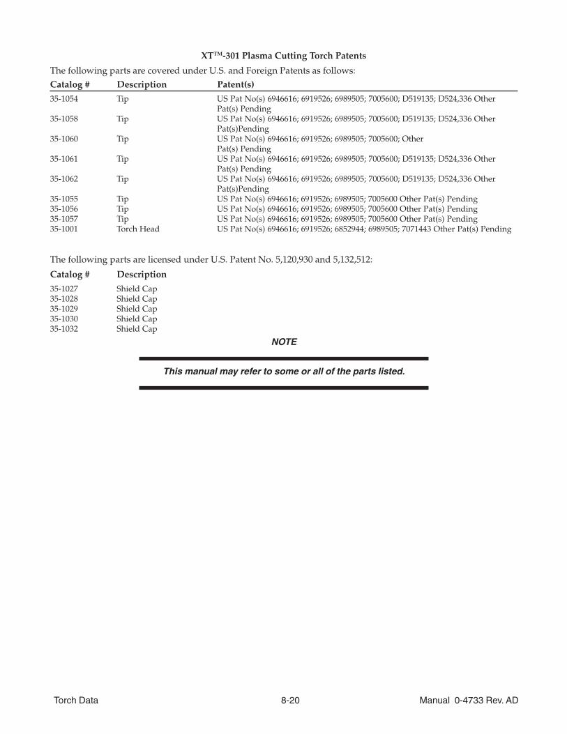
XTTM-301 Plasma Cutting Torch Patents
The following parts are covered under U.S. and Foreign Patents as follows:Catalog # Description Patent(s)
35-1054 Tip US Pat No(s) 6946616; 6919526; 6989505; 7005600; D519135; D524,336 OtherPat(s) Pending
35-1058 Tip US Pat No(s) 6946616; 6919526; 6989505; 7005600; D519135; D524,336 OtherPat(s)Pending
35-1060 Tip US Pat No(s) 6946616; 6919526; 6989505; 7005600; OtherPat(s) Pending
35-1061 Tip US Pat No(s) 6946616; 6919526; 6989505; 7005600; D519135; D524,336 OtherPat(s) Pending
35-1062 Tip US Pat No(s) 6946616; 6919526; 6989505; 7005600; D519135; D524,336 OtherPat(s)Pending
35-1055 Tip US Pat No(s) 6946616; 6919526; 6989505; 7005600 Other Pat(s) Pending35-1056 Tip US Pat No(s) 6946616; 6919526; 6989505; 7005600 Other Pat(s) Pending35-1057 Tip US Pat No(s) 6946616; 6919526; 6989505; 7005600 Other Pat(s) Pending35-1001 Torch Head US Pat No(s) 6946616; 6919526; 6852944; 6989505; 7071443 Other Pat(s) Pending
The following parts are licensed under U.S. Patent No. 5,120,930 and 5,132,512:
Catalog # Description
35-1027 Shield Cap35-1028 Shield Cap35-1029 Shield Cap35-1030 Shield Cap35-1032 Shield Cap
NOTE
This manual may refer to some or all of the parts listed.