Embed Size (px)
Citation preview

8-Reliability and Channel Coding
Dr. John P. Abraham
Professor
UTPA

sources of transmission errors
• All data communication systems are susceptible to errors. Devices fail. Equipment that does not meet the engineering standards. We need to have ways to control and recover from errors– Interference– Distortion– Attenuation

Effect of transmission errors on data
• Single bit error– Result from very short-duration interference
• Burst Error – Multiple bits in a block of bits are changed.
Results from longer-duration interference
• Erasure– Does not correspond to either a logical 1 or 0.
Can result from distortion or intereference.
Link Layer
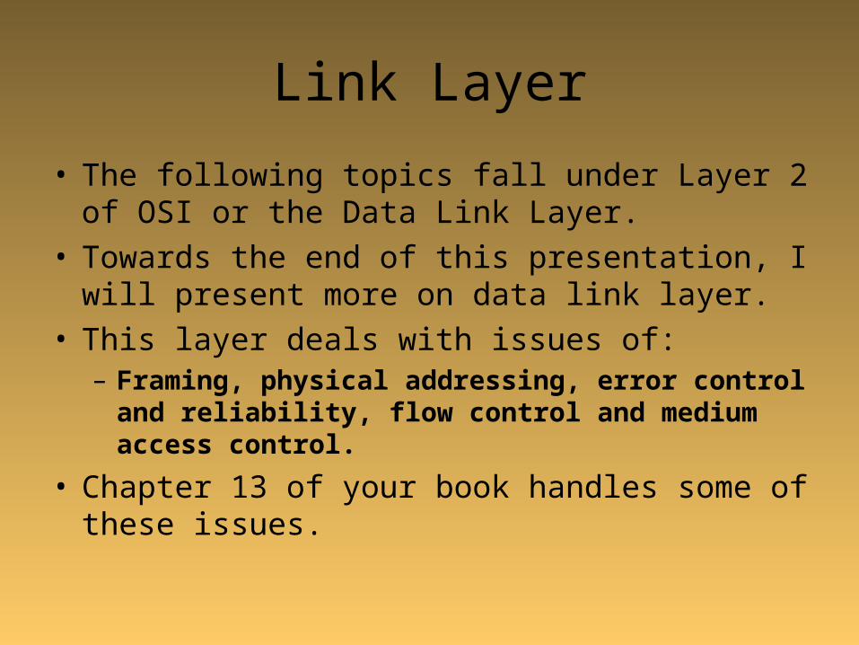
• The following topics fall under Layer 2 of OSI or the Data Link Layer.
• Towards the end of this presentation, I will present more on data link layer.
• This layer deals with issues of:– Framing, physical addressing, error control and
reliability, flow control and medium access control.
• Chapter 13 of your book handles some of these issues.

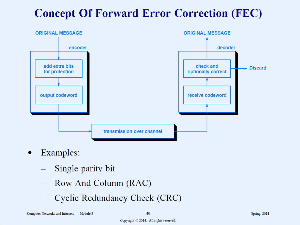
Strategies for Handling channel Errors. Channel Coding
• Forward Error Correction (FEC)– Add additional bits for detection and
correction.
• Automatic Repeat reQuest (ARQ)– Sender and receiver exchange messages to
indicate to insure all data arrives correctly.

Single parity bit
• Explain odd or even parity
• Show examples

RAC Detection

CRC introduced by Hamming
• Used in high speed data networks
• 3 key aspects:– CRC supports Arbitrary length message– Excellent error detection– Fast Hardware implementation, CPU can do
CRC computation fast

Theory behind CRC
• Given a from of k-bit
• Transmitter generates n-bit sequence called FCS (frame check sequence)
• The k+n bit is divisible by some predetermined number.
• The receiver divides the total by the predetermined number. If no remainder, then the block is fine.

Error Correction Techniques
• Hamming code
• Chapter 8 ends here

Chapter 9 – Transmission modes
• Two fundamental categories– Parallel –multiple bits at the same time– Serial – one bit at a time

Parallel transmission
• High throughput
• Transmission through buses uses parallel transmission– Control bus, address bus and data bus
• Parallel printer ports using parallel transmission

Serial transmission• My handwritten notes
• Parallel data is converted to serial data by UART (Universal Asynchronous Receiver and Transmitter) found which is connected to RS232 serial ports.
• USART (Synchronous) chip handles transmission for synchronous networks.
• Bits are arranged in order based on little Endian or big Endian
• Timing of serial transmission is very important determine boundaries.

Asynchronous transmission
• A computer can send any time. No timing coordination exists between sender and receiver.
• There must enough information in data send to determine boundaries.
• So, extra overhead is required such as preemble, start and stop bits, etc.
• Try mode from command prompt• Try changing it – mode: 2400, o, 8• Alternatively go to serial port from device manager and
set it from there.

Synchronous transmission
• Bits are transmitted continuously without idle bits.
• Synchronization is achieved various ways. Some of these are explained my notes.

Frames
• It is unusual for a computer to have data to send continuously.
• So it is easier to collect bits into blocks of bits and then create a frame from the blocks.
• Now sending computer can add distinguishing marks at the beginning and end of each frame.– Character counting– Bit stuffing etc. had been used.

Isochronous transmission
• The speed is predetermined.
• Steady bit flow for multimedia applications. Buffering handles speed differences

Simplex, half-duplex, full duplex transmission
• Simplex – send one direction only (radio)
• Half – duplex: Send and receive, but channel (cb radio)
• Full duplex: Send and receive two channels

DCE and DTE
• Already discussed
• Chapter 9 ends here

Chapter 10
• Modulation and Modems
• I would refer you to my notes for this one
• We discussed this in class as well (remember PSK, ASK, and FSK)

Chapter 11
• Multiplexing, Demultiplexing
• We already discussed FDM, TDM and statistical
• Wavelength Division Multiplexing is used for Fiber. We divide light into its components
• There are telephone multiplexing technologies not discussed here
---------------------------------------- end--------------

ARQ
• Receiving side send Ack back if the message arrived correctly.
• If timed out the message is resent• ARQ is provided if only error detection is
implemented without error correction.• There are 3 types of ARQ
– Stop and wait– Go-back-n– Selective repeat

Sliding Window Protocols
• For full duplex two transmission lines are required• One to send data and the other to receive data and/or
ACKs• Sending ACKs in a packet of its own is waste of
resources• May use pggybacking• The acknowledgement is attached to an outgoing data
frame(ack field in the frame header)• Data link layer must wait until it has some thing to send
before it can ack.• This may cause time out and the frame may be re-sent.

• The essence of sliding window protocols is that at any instant of time, the sender maintains a set of sequence numbers corresponding to frames it is permitted to send. These frames are said to fall within the sending window. Similarly, the receiver also maintains a receiving window corresponding to the set of frames it is permitted to accept. It is NOT necessary for the sender and receiver to have same number limits.
• Sequence numbers of frames sent but not acknowledged are kept in the senders window.
• Th receivers window corresponds to the frames it may accept.
• See page 434 in your text book.

One bit sliding window protocol
• uses stop and wait scheme, since the sender transmits a frame and waits for its acknowledgement before sending the next one.
• The acknowledgement field of the frame contains the number of the last frame received without error. If this number agrees with the sequence number of the frame the sender is trying to send, the sender knows that it is done and can proceed with the next frame.

A protocol using Go-Back-N
• Takes into account of round trip transmission time.• Enough frames should be send to stuff the band with to
avoid channel idling• Consider a 50-kbps satellite channel with 500 m-sec
round-trip propagation delay– Let us send 1000 bit frames
– At t=0 starts sending the first frame, at t=20 msec the frames has been send
– Receiver fully receives only at t=270msc, and ack will be received at t=520 msec.
– Sender would be blocked 96% of time- only 4% of available band width was used.

Go-Back-N continued.
• Instead of sending 4 frames, the sender should have sent 26 frames. This will take t=520 msec.
• at t=520 the acknowledgement for the first frame will be received. The senders maximum window size is 26.
• This technique is called pipelining.• If a frame in the middle of a stream gets damaged, what should
the receiver do? Should all frames starting at that point be re-sent?
• Go-Back-N simply discards all frames including the damaged one, not sending acks. The time out at the sender will resend all subsequent frames.
• Can waste a lot of bandwidth in an unreliable channel.

Selective Repeat
• Receiver stores all good frames after the damaged frame.
• Notifies the sender of the bad frame, and sender re-sends that one.
• This technique requires the data link layer to have large amount of memory for the cache.

Data Link Layer• Framing: bits from physical layer are grouped into
units called frames. To distinguish one frame from the other there are frame delimiting techniques used such as byte or bit stuffing. Discussed in later chapters. A frame contains a header (control information) and the payload (data).
• Physical addressing – a 48 bit addressing scheme for Ethernet.
• Error control and reliability CRC, checksum, etc.- already discussed above.
• Flow control – sliding window discussed above.• Medium Access – CSMA-CD and others discussed
later.• Bridging – connecting two LANS into one.

Point to Point Protocol (PPP)
• Used by ADSL (PPP over Ethernet) or POTS.• Derived from High-Level Data Link Control (HDLC)• PPP logs-in to authenticate using LCP (link control
protocol)• PPPoE used in ADSL runs in two stages: The
discovery stage and the PPP session stage.– The discovery stage, user station discovers the MAC
address of the access concentrator at the ISP.– In the session stage a session ID is assigned.