Embed Size (px)
Citation preview

Lin
ea
r Re
fere
nc
ing
in A
rcG
IS™
ArcGIS™ 8
Linear Referencing in ArcGIS™
$14.9592306
xxxx10/02spPrinted in USA
Linear Referencing in ArcGIS™
GIS by ESRI ™
Linear referencing in the ESRI® ArcGIS™ Desktop products suite—ArcView®, ArcEditor™, and ArcInfo™—enables users to create, manage,
display, query, and analyze data whose relative position has been modeled along a linear feature. Linear referencing in ArcView allows
users to display and query route and event data. Linear referencing in ArcEditor and ArcInfo supports creation and editing of route data.
Linear referencing in ArcInfo provides a variety of event geoprocessing operations that allow event data to be spatially analyzed.
You will learn how to
• Create route data from existing line data.
• Calibrate routes with points.
• Migrate existing route data to a geodatabase.
• Display hatches on linear features.
• Find and identify route locations.
• Display route events (dynamic segmentation).
• Edit route and event data.
• Perform a variety of geoprocessing operations with event data (overlay events, transform events, and so on).
Begin by following the quick-start tutorial to get an overview of how to execute the basic linear referencing functions. If you prefer, jump
right in and experiment on your own. When you have questions, you will find concise, step-by-step answers inside, fully illustrated, to
help you complete a task.
ESRI • 380 New York Street • Redlands, CA 92373-8100 • USA909-793-2853 • FAX 909-793-5953 • www.esri.com
™
ISBN 1-58948-063-5

Copyright © 2002 ESRIAll rights reserved.Printed in the United States of America.
The information contained in this document is the exclusive property of ESRI. This work is protected under United States copyright law and otherinternational copyright treaties and conventions. No part of this work may be reproduced or transmitted in any form or by any means, electronic ormechanical, including photocopying and recording, or by any information storage or retrieval system, except as expressly permitted in writing by ESRI. Allrequests should be sent to Attention: Contracts Manager, ESRI, 380 New York Street, Redlands, CA 92373-8100, USA.
The information contained in this document is subject to change without notice.
DATA CREDITS
Highways and streets map—Maryland Department of Transportation State Highway Administration, Baltimore, Maryland
Transit map—Parsons Brinckerhoff Quade & Douglas, Inc., Los Angeles, California
Railways map—Parsons Brinckerhoff Quade & Douglas, Inc., Los Angeles, California
Oil and gas exploration map—TGS-NOPEC Geophysical Company, Houston, Texas
Pipelines map—M.J. Harden Associates, Inc., Kansas City, Missouri
Water resources map—Center for Research in Water Resources, University of Texas at Austin
Hatching map 1—New York State Department of Transportation, Albany, New York
Hatching map 2—TGS-NOPEC Geophysical Company, Houston, Texas
WRITER
Patrick Brennan
U.S. GOVERNMENT RESTRICTED/LIMITED RIGHTSAny software, documentation, and/or data delivered hereunder is subject to the terms of the License Agreement. In no event shall the U.S. Government acquire
greater than RESTRICTED/LIMITED RIGHTS. At a minimum, use, duplication, or disclosure by the U.S. Government is subject to restrictions as set forth in
FAR §52.227-14 Alternates I, II, and III (JUN 1987); FAR §52.227-19 (JUN 1987) and/or FAR §12.211/12.212 (Commercial Technical Data/Computer
Software); and DFARS §252.227-7015 (NOV 1995) (Technical Data) and/or DFARS §227.7202 (Computer Software), as applicable. Contractor/Manufacturer
is ESRI, 380 New York Street, Redlands, CA 92373-8100, USA.
ESRI, the ESRI globe logo, ArcGIS, ArcToolbox, ArcCatalog, ArcMap, ArcInfo, ArcSDE, GIS by ESRI, ArcView, ArcEditor, the ArcGIS logo, and www.esri.com
are trademarks, registered trademarks, or service marks of ESRI in the United States, the European Community, or certain other jurisdictions.
Other companies and products mentioned herein are trademarks or registered trademarks of their respective trademark owners.
copyright.P65 11/11/2002, 3:20 PM1

IN THIS CHAPTER
9
Quick-start tutorial 2• Exercise 1: Organizing your data
in ArcCatalog
• Exercise 2: Creating andcalibrating route data
• Exercise 3: Displaying andquerying routes
• Exercise 4: Displaying andquerying route events
• Exercise 5: Editing routes
ArcGIS has the tools you need for linear referencing applications. The easiestway to start learning about linear referencing is to complete the exercises in thistutorial. Before you start, however, it is assumed you know the fundamentals ofArcToolbox™, ArcCatalog™, and ArcMap™ software. For more information, seeUsing ArcToolbox, Using ArcCatalog, Using ArcMap, and Editing in ArcMap.
For this tutorial, imagine that you work in the GIS department of a highwayauthority responsible for the maintenance and safety of your region’s highways. Inthe exercises to follow, you will perform some of the linear referencing taskstypical to such a person. Specifically, you will use ArcToolbox to create andrecalibrate route data. Next, you will learn how to display and query your newlycreated route data in ArcMap. After that, you will discover how easy it is todisplay and query your route event data in ArcMap. Lastly, you will learn how toedit your route data in ArcMap.
To complete many of the exercises in this tutorial, you will need to have anArcInfo™ license. Feel free, however, to read through the exercises to familiarizeyourself with the linear referencing functionality in ArcGIS.
Work on this tutorial at your own pace. The exercises build on one another, so it isassumed that you will complete them in order. This tutorial includes five exercises,each of which takes five to 30 minutes to complete.
The study area for this tutorial is Pitt County, North Carolina. The data wascompiled from various sources and has been modified to suit the needs of theexercises. The reliability and suitability of the information, therefore, cannot beguaranteed.
ch02.p65 11/11/2002, 5:52 PM9

10 LINEAR REFERENCING IN ARCGIS
Exercise 1: Organizing your data in ArcCatalog
The exercises in this chapter use the tutorial data distributedwith ArcGIS. The default install location of the data isC:\arcgis\ArcTutor\LinearReferencing. Some of thefollowing exercises require that you change the data. Youwill, therefore, need to have write access to the data. If youdo not want to change the data at the default location oryou do not have write access, you will need to copy theLinearReferencing folder to a new location before you startthe exercises.
Connecting to the data
In ArcCatalog, folder connections let you access directorieson local disks or shared folders on the network. Further,database connections allow you to access the contents of adatabase.
1. Start ArcCatalog by either double-clicking a shortcutinstalled on your desktop or using the Programs list inyour Start menu.
2. Click the Connect To Folder button on the Standardtoolbar.
2
3. Navigate to the LinearReferencing folder on the localdrive where you installed the tutorial data.
4. Click OK.
The new folder connection is now listed in the Catalog tree.You will now be able to access all of the data needed forthe remaining exercises in this tutorial via the newconnection.
4
3
ch02.p65 11/11/2002, 5:52 PM10

QUICK-START TUTORIAL 11
Exercise 2: Creating and calibrating route data
The first thing you will need for any linear referencingproject is accurate route data. In this exercise, you will firstcreate a route feature class by merging input line featuresthat share a common route identifier. This is done with theCreate Routes Wizard, which is in ArcToolbox.
Next, you will recalibrate the newly created route featureclass using a point feature class that stores route andmeasure information as attributes. This is done with theCalibrate Routes Wizard, which is also in ArcToolbox.
Creating route data
The Create Routes Wizard is used to specify the input linefeature class, the route identifier field, the method used toset the route measures, and the output feature class. Notethat the input feature classes can be any supported format.This includes coverage, shapefile, personal and enterprisegeodatabase, and computer-aided design (CAD) data.
1. Start ArcToolbox by either double-clicking a shortcutinstalled on your desktop or using the Programs list inyour Start menu.
2. Double-click the Create Routes Wizard in ArcToolbox inthe Linear Referencing toolset of Data ManagementTools.
3
4
5
There are several ways to set the input feature class. Youcan drag a line feature class from the ArcCatalog tree anddrop it onto the text box, click the Browse button to openthe ArcCatalog minibrowser and navigate to the featureclass, or simply type the full pathname to the feature classin the text box.
The tutorial instructions will simply ask you to type namesand paths into the appropriate text boxes. Feel free,however, to use any of the available techniques.
3. Type “C:\arcgis\ArcTutor\LinearReferencing\PITT.mdb\PITT\base_roads” for the Input FeatureClass.
4. Click the Route Identifier Field dropdown arrow andclick ROUTE1. The values in the route identifier fielduniquely identify each route.
5. Click Next.
2
ch02.p65 11/11/2002, 5:52 PM11

12 LINEAR REFERENCING IN ARCGIS
This panel asks you to specify how the route measures willbe obtained. There are three choices:
• The geometric lengths of the input features are used toaccumulate the measures.
• A value stored in a measure field is used to accumulatethe measures.
• The values stored in from- and to-measure fields areused to set the measures.
You will use the third method.
6. Click Use two fields from the input feature class.
7. Click the From-Measure field dropdown arrow and clickBEGMP1.
8. Click the To-Measure field dropdown arrow and clickENDMP1.
9. Click Next.
The output routes can be written to a shapefile or ageodatabase feature class. You will be writing to a newfeature class in the same feature dataset as the inputfeature class.
10. Click Feature class in a geodatabase.
11. Click Next.
If your input features have a defined projection, the CreateRoutes Wizard will preserve this projection. You can chooseto change the projection information for the output, in whichcase the features will automatically be projected. Note thatyou cannot change the projection if you are writing to anexisting feature dataset.
Whenever writing routes to a geodatabase, you shouldalways set the m domain. A default m domain will becalculated for you, but this might not accurately reflect yourneeds.
8
9
6
7
W
Q
ch02.p65 11/11/2002, 5:52 PM12

QUICK-START TUTORIAL 13
P
O
I
12. Type “C:\arcgis\ArcTutor\LinearReferencing\PITT.mdb” for the Output Geodatabase.
13. Click the dataset dropdown arrow and click the PITTdataset.
14. Type “routes” for the name of the new feature class.
15. Click Change Settings.
17. Click the M Domain tab.
18. Type “-1000” for the Min and “10000” for the Precision.These settings will ensure that your route measures willbe accurate to four decimal places.
U
A
19. Click OK.
20. Click OK on the Output Settings dialog box.
At this point, you will have returned to the Enter theoutput feature class panel.
21. Click Next on the Create Routes Wizard.
R
E
T
Y
S
16. Click Change.
ch02.p65 11/11/2002, 5:52 PM13

14 LINEAR REFERENCING IN ARCGIS
DF
J
G
H
Not all features from the input feature class have route andmeasure information. These features represent roads thatare not currently maintained by the highway authority anddo not need to be included in the output route feature class.You will exclude these features from the route creationprocess by specifying a query.
22. Click Use only those features that satisfy a query.
23. Click the Click to define a query button.
24. Type “[ROUTE1] < > 0” in the text box.
25. Click OK.
26. Click Next on the Create Routes Wizard.
27. Review your settings and click Finish.
K
ch02.p65 11/11/2002, 5:52 PM14

QUICK-START TUTORIAL 15
Calibrating route data
Imagine that at some point in the future, the highwayauthority’s road maintenance crew acquired a distancemeasuring instrument (DMI) so that they could accuratelyrecord mileage information along the highways. For asample set of highways, the crew went out and capturedmileage information approximately every 1/10 of a mile.The results of this effort were stored as points in ashapefile, where the route and mileage information wasstored as attributes.
In the next section of this tutorial, you will use the CalibrateRoutes Wizard to adjust the measures of the routes you justcreated to match those of the points in the shapefile. Theresult will be written to a new feature class.
The Calibrate Routes Wizard is used to specify the inputroute feature class, the route identifier field, the input pointfeature class, the measure field, the methods used to set theroute measures, and the output feature class. Note that theinput route feature classes can be any supported format.This includes coverage, shapefile, personal and enterprisegeodatabase, and CAD data.
Note that in addition to being able to adjust the measures ofexisting routes, the Calibrate Routes Wizard can also beused to create new routes by merging unmeasured inputline features using a common route identifier and setting themeasure information using the point attributes. To mimic theacquisition of more accurate data over time, however, theprocess was split into two separate tasks for this exercise.
1. Double-click the Calibrate Routes Wizard in ArcToolboxin the Linear Referencing toolset of Data ManagementTools.
2. Type “C:\arcgis\ArcTutor\LinearReferencing\PITT.mdb\PITT\routes” for the Input Feature Class.
3. The values in the route identifier field uniquely identifyeach route. Click the Route Identifier Field dropdownarrow and click ROUTE1.
4. Click Next.
1
2
3
4
ch02.p65 11/11/2002, 5:52 PM15

16 LINEAR REFERENCING IN ARCGIS
7
8
9
5
6
5. Type “C:\arcgis\ArcTutor\LinearReferencing\Calibration_Points.shp” for the Point Feature Class.
6. Click the Point Identifier Field dropdown arrow and clickROUTE1.
7. Click the Measure dropdown arrow and clickMEASURE.
A tolerance can be specified to limit how far a calibrationpoint can be from its route. Points outside the tolerance willnot be used by the calibration process. The tolerance isexpressed in the same units as the route feature class’scoordinate system.
8. Type “5” for the tolerance. This is more than enough forthe data that is being used here.
9. Click Next.
If your point features have a projection that differs from theroute features, the Calibrate Routes Wizard will project thepoints to match the routes before the calibration processstarts.
Either whole or partial routes can be calibrated. You canchoose to interpolate between the input points, extrapolatebefore the input points, extrapolate after the input points, oruse any combination of these three methods.
Note that the Extrapolate before calibration points,Interpolate between calibration points, and Extrapolate aftercalibration points check boxes are checked by default.
10. Click Next.
Q
ch02.p65 11/11/2002, 5:52 PM16
QUICK-START TUTORIAL 17
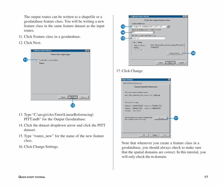
The output routes can be written to a shapefile or ageodatabase feature class. You will be writing a newfeature class in the same feature dataset as the inputroutes.
11. Click Feature class in a geodatabase.
12. Click Next.
13. Type “C:\arcgis\ArcTutor\LinearReferencing\PITT.mdb” for the Output Geodatabase.
14. Click the dataset dropdown arrow and click the PITTdataset.
15. Type “routes_new” for the name of the new featureclass.
16. Click Change Settings.
17. Click Change.
Note that whenever you create a feature class in ageodatabase, you should always check to make surethat the spatial domains are correct. In this tutorial, youwill only check the m domain.
E
W
I
Y
T
U
R
ch02.p65 11/11/2002, 5:52 PM17

18 LINEAR REFERENCING IN ARCGIS
18. Click the M Domain tab.
19. Type “-1000” for the Min and “10000” for the Precision.These settings will ensure that your route measures willbe accurate to four decimal places.
20. Click OK.
21. Click OK.
At this point, you will have returned to the Enter theoutput feature class panel.
22. Click Next.
23. Click Next.
24. Review your settings and click Finish.
In this exercise, you learned how to create a route featureclass by merging input line features that shared a commonidentifier and how to adjust the route measures usingmeasure information stored in a point shapefile. For moreinformation on creating and calibrating route data, seeChapter 4, ‘Creating route data’.
A
P
O
F
G
ch02.p65 11/11/2002, 5:52 PM18

QUICK-START TUTORIAL 19
Exercise 3: Displaying and querying routes
In this exercise, you will add the route data you created inExercise 2 to an existing map document and symbolize it.You will then
• Set the route identifier field.
• Add the Identify Route Locations tool to a toolbar.
• Identify route locations.
• Find route locations.
• Display route measure anomalies.
Opening an existing map document
Before you can complete this exercise, you must startArcMap.
1. Double-click a shortcut installed on your desktop or usethe Programs list in your Start menu to start ArcMap.
2. Click Open from the ArcMap File menu.
2
3
4
3. Click the Look in dropdown arrow in the Open dialogbox and navigate to the folder where you installed thedata for this tutorial.
4. Double-click Ex3.mxd. ArcMap opens the map.
This map contains the following layers in a data framecalled Pitt County:
calibration_points The points used in Exercise 2 to recalibrate the route measures
base_roads All of the roads in Pitt County
city boundaries The boundaries of the cities in PittCounty
county boundary Pitt County boundary
ch02.p65 11/11/2002, 5:52 PM19

20 LINEAR REFERENCING IN ARCGIS
The map currently displays the city boundaries and countyboundary layers. Their check boxes are checked in thetable of contents. The calibration_points layer is checked,but scale suppression has been set. It will only be visiblewhen you zoom in to a scale beyond 1:25,000.
5. Click the check box for the base_roads layer in the tableof contents.
5
You will now see all of the roads in Pitt County. Thisincludes roads not maintained by the highway authority. Theroads maintained by the highway authority were written tothe routes feature class.
Adding route data to your map
1. Click the Add Data button on the ArcMap Standardtoolbar.
2. Click the Look in dropdown arrow and navigate towhere you installed tutorial data. Double-click Pitt.mdband double-click the Pitt feature dataset.
3. With the Ctrl key pressed down, select both the routesand routes_new feature classes.
4. Click Add. You will see two new layers in the table ofcontents.
1
2
3
4
Changing the display symbol
The colors and symbols ArcMap chose to display for theroutes layer might make it difficult to see where the routefeatures are located. It is easy to change the colors andsymbols used to display features in ArcMap.
1. Click the line symbol in the table of contents for theroutes layer to display the Symbol Selector dialog box.
1
ch02.p65 11/11/2002, 5:52 PM20

QUICK-START TUTORIAL 21
2. Scroll down until you find a symbol you like and click it.
3. Click OK. Your routes layer will be displayed with thesymbol you chose.
3
4. Repeat steps 1 through 3 for the routes_new layer.
You can also open the Symbol Selector dialog box by right-clicking the layer in the table of contents, clickingProperties, and clicking the Symbology tab. To simplychange the color of a symbol, right-click the symbol in thetable of contents to display the color palette. For moreinformation on changing display symbols, see UsingArcMap.
Setting the Route Identifier field
ArcMap knows whenever route data has been added to amap and exposes some additional layer properties. One ofthese properties is the Route Identifier field. This fielduniquely identifies each route.
Setting the Route Identifier field is not required. Doing so,however, reduces the number of steps required to use manyof the ArcMap Linear Referencing dialog boxes, wizards,and tools.
1. Right-click the routes layer in the table of contents andclick Properties.
1
ch02.p65 11/11/2002, 5:52 PM21
22 LINEAR REFERENCING IN ARCGIS
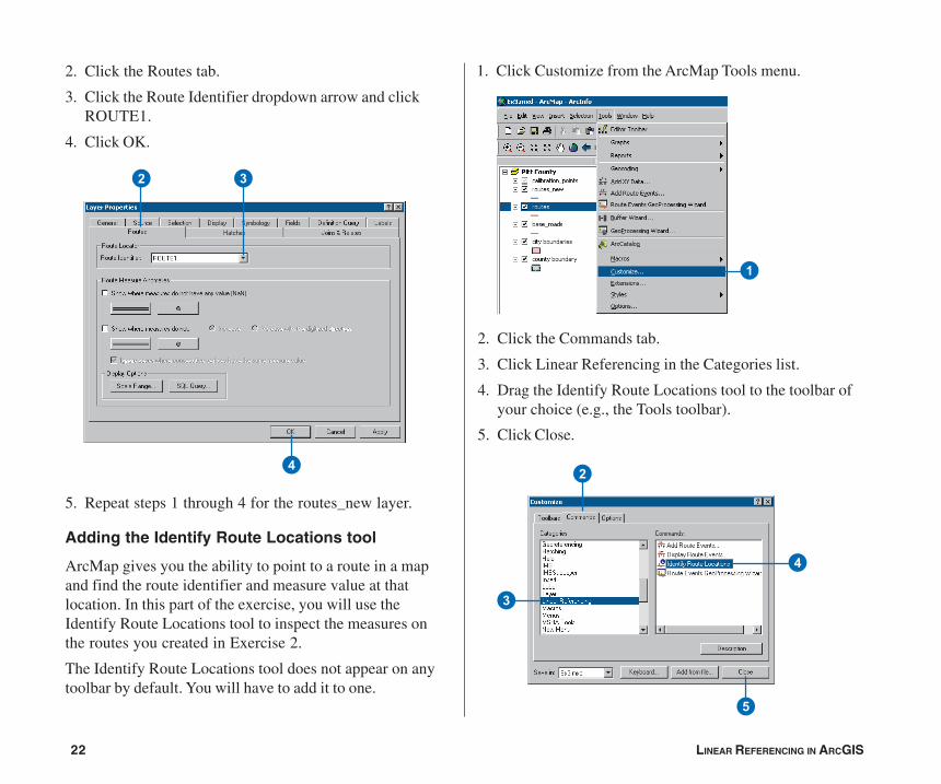
2. Click the Routes tab.
3. Click the Route Identifier dropdown arrow and clickROUTE1.
4. Click OK.
2 3
4
1. Click Customize from the ArcMap Tools menu.
2. Click the Commands tab.
3. Click Linear Referencing in the Categories list.
4. Drag the Identify Route Locations tool to the toolbar ofyour choice (e.g., the Tools toolbar).
5. Click Close.
1
5. Repeat steps 1 through 4 for the routes_new layer.
Adding the Identify Route Locations tool
ArcMap gives you the ability to point to a route in a mapand find the route identifier and measure value at thatlocation. In this part of the exercise, you will use theIdentify Route Locations tool to inspect the measures onthe routes you created in Exercise 2.
The Identify Route Locations tool does not appear on anytoolbar by default. You will have to add it to one.
2
3
4
5
ch02.p65 11/11/2002, 5:52 PM22

QUICK-START TUTORIAL 23
1
2
4
5
Identifying route locations
In ArcMap, a bookmark is a saved map location. Abookmark containing some of the calibration points used inExercise 2 to recalibrate the routes has been created foryou.
1. Point to Bookmarks from the ArcMap View menu andclick Calibration Points.
When ArcMap moves to the saved location, the calibrationpoints appear with labels that represent the measure valuesfor each point. The reason they appear when the bookmarkhas been used is because scale suppression was set on thelayer. For more information on scale suppression, see UsingArcMap.
2. Click the Identify Route Locations button.
3. Move the mouse pointer over one of the calibrationpoints and click. Route locations from both the routesand routes_new layers will be identified.
4. Click the route node for each of the route layers.
The numeric value listed for each of these nodescorresponds to the value stored in the Route Identifierfield, which you set in a previous section of thisexercise. Note that the measure value for the two routesdiffers. Note further that the measure value for theroutes_new layer corresponds closely to the measurevalue of the calibration point you clicked (the closer youare to a calibration point, the closer the measure will be).
5. Right-click the route node for one of the layers andexplore the context choices available to you.
ch02.p65 11/11/2002, 5:52 PM23

24 LINEAR REFERENCING IN ARCGIS
6
1
2
3
4
5
6
7
6. Uncheck the check box for the calibration_points layerin the table of contents to make it not visible. It will notbe used any further in this exercise.
7. Close the Identify Route Location Results window.
Finding route locations
In many linear referencing applications, you will discoverthat you will often need to find a location along a route. Forexample, you may need to find where an accident occurredalong a highway. On a paper map, it is hard to find a routelocation. This is because route measures are typically notshown. In ArcMap, finding a route location is made easy.
1. Click the Find button on the ArcMap Tools toolbar.
2. Click the Route Locations tab.
3. Click the Route Reference dropdown arrow and clickroutes_new.
Notice that the field listed in the Route Identifier dropdownarrow corresponds to the Route Identifier field you setpreviously in this exercise.
4. Type “30000121” in the Route text box.
5. Type “5” in the Location text box.
6. Click Find.
7. Right-click the route location that was found and explorethe context choices available to you.
8. Close the Find dialog box.
ch02.p65 11/11/2002, 5:52 PM24
QUICK-START TUTORIAL 25
1
2
3
45
6
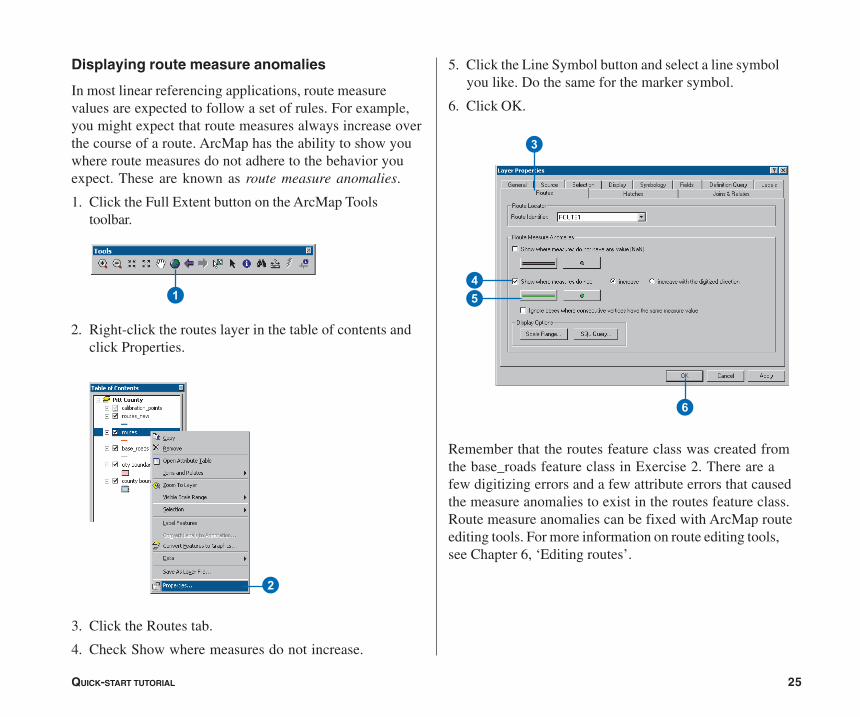
Displaying route measure anomalies
In most linear referencing applications, route measurevalues are expected to follow a set of rules. For example,you might expect that route measures always increase overthe course of a route. ArcMap has the ability to show youwhere route measures do not adhere to the behavior youexpect. These are known as route measure anomalies.
1. Click the Full Extent button on the ArcMap Toolstoolbar.
2. Right-click the routes layer in the table of contents andclick Properties.
3. Click the Routes tab.
4. Check Show where measures do not increase.
5. Click the Line Symbol button and select a line symbolyou like. Do the same for the marker symbol.
6. Click OK.
Remember that the routes feature class was created fromthe base_roads feature class in Exercise 2. There are afew digitizing errors and a few attribute errors that causedthe measure anomalies to exist in the routes feature class.Route measure anomalies can be fixed with ArcMap routeediting tools. For more information on route editing tools,see Chapter 6, ‘Editing routes’.
ch02.p65 11/11/2002, 5:52 PM25

26 LINEAR REFERENCING IN ARCGIS
Exercise 4: Displaying and querying route events
In this exercise, you will create a new event table thatrepresents where injury accidents occurred along sectionsof poor-quality pavement. To do this, you will first use theAdd Route Events dialog box to display the accidentlocation and pavement quality event data on your map. Youwill then use the Select By Attributes dialog box to selectthe injury accidents and poor-quality pavement locations.Finally, you will use the Route Events GeoProcessingWizard to create a new event table whose recordsrepresent where injury accidents occurred along poor-quality pavement.
Opening an existing map document
Before you can complete this exercise, you must startArcMap.
1. Double-click a shortcut installed on your desktop or usethe Programs list in your Start menu to start ArcMap.
2. Click Open from the ArcMap File menu.
3
4
3. Click the Look in dropdown arrow in the Open dialogbox and navigate to the folder where you installed thedata for this tutorial.
4. Double-click Ex4.mxd. ArcMap opens the map.
This map contains the following layers in a data framecalled Pitt County:
routes_hwy Shapefile copy of routes_newfeature class you created inExercise 2
county boundary Pitt County boundary
accident Point event table storing accidentinformation
pavement Line event table storing pavementinformation
base_roads All of the roads in Pitt County
2
ch02.p65 11/11/2002, 5:52 PM26

QUICK-START TUTORIAL 27
Displaying point events on your map
The accident table is a point event table. Point events occurat a precise point location along a route. In this section ofthe exercise, you will display the accident event data as alayer.
1. Click Add Route Events from the ArcMap Tools menu.
2. Click the Route Reference dropdown arrow and clickroutes_hwy.
3. Click the Route Identifier dropdown arrow and clickROUTE1.
4. Click the Event Table dropdown arrow and clickaccident.
5. Click the Route Identifier dropdown arrow and clickROUTE1.
6. Click the Measure dropdown arrow and clickMEASURE.
7. Click OK.
A new layer—accident Events—has been added to yourmap.
1
2
4
5
6
7
3
ch02.p65 11/11/2002, 5:52 PM27

28 LINEAR REFERENCING IN ARCGIS
1
2
4
5
7
9
3
6
8
Displaying line events on your map
The pavement table is a line event table. Line events differfrom point events in that they have two measure fields thatdefine a portion of a route. The procedure for adding lineevents to your map is almost the same as adding pointevents.
1. Click Add Route Events from the ArcMap Tools menu.
2. Click the Route Reference dropdown arrow and clickroutes_hwy.
3. Click the Route Identifier dropdown arrow and clickROUTE1.
4. Click the Event Table dropdown arrow and clickpavement.
5. Click the Route Identifier dropdown arrow and clickROUTE1.
6. Click Line Events.
7. Click the From-Measure dropdown arrow and clickBEGIN_MP.
8. Click the To-Measure dropdown arrow and clickEND_MP.
9. Click OK.
A new layer—pavement Events—has been added to yourmap.
ch02.p65 11/11/2002, 5:52 PM28

QUICK-START TUTORIAL 29
Querying events
Layers based on an event table can be queried in manyways. They can be identified by clicking them, they can beselected by dragging a box or clicking them on the map,they can be selected by clicking them in an attribute table,and they can be selected using a Structured QueryLanguage (SQL) expression. You will use the Select ByAttributes dialog box to input SQL expressions to select theevent records needed for this exercise. Specifically, you willselect injury accidents and poor quality pavement.
1. Click Select By Attributes from the ArcMap Selectionmenu.
1
2. Click the Layer dropdown arrow and click accidentEvents.
3. Type the following in the text box:“NUM_INJURY” > 0
4. Click Apply.
5. Click the Layer dropdown arrow and click pavementEvents.
6. Type the following in the text box: “RATING” < 50
7. Click Apply.
8. Click Close.
7
8
6
5
3
4
2
ch02.p65 11/11/2002, 5:52 PM29

30 LINEAR REFERENCING IN ARCGIS
1
2
3
4
5
6
7
There are many events selected on your map. In the nextsection of this exercise, you will use the Route EventsGeoProcessing Wizard to intersect the two event layers.The result will be a table that contains the injury accidentsthat happened on poor-quality pavement. All attributes fromboth inputs are maintained.
Intersecting event layers
1. Click Route Events GeoProcessing Wizard from theArcMap Tools menu.
2. Intersect two route event layers is the default. ClickNext.
3. Click the input route event layer dropdown arrow andclick accident Events.
4. Click the overlay route event layer dropdown arrow andclick pavement Events.
5. Click Next.
6. Type “C:\arcgis\ArcTutor\LinearReferencing\AccPav.dbf” for the output route event table.
7. Click Finish.
ch02.p65 11/11/2002, 5:52 PM30

QUICK-START TUTORIAL 31
8
A new layer—AccPav Events—will be added to your map.It will be hard to see, however, because the accident andpavement event layers are still visible.
8. Turn off the accident and pavement layers by clickingtheir check boxes in the table of contents.
You will now see only the injury events that occurred alongpoor quality pavement. Each of these new events has all ofthe attributes from both the accident and pavement tables.
For more information on the display and query of events orthe spatial analysis of events, see Chapter 5, ‘Displayingand querying routes and events’, and Chapter 7, ‘Creatingand editing event data’.
ch02.p65 11/11/2002, 5:52 PM31

32 LINEAR REFERENCING IN ARCGIS
Exercise 5: Editing routes
There are a number of tools in ArcMap that make theinteractive creation and editing of route measures easy. Inthis exercise, you will create a new route from a selectedset of linear features and set its identifier. You will thenconvert the measures of this newly created route from feetto miles. Lastly, you will recalibrate the route using knownmeasure values at specific locations on your map.
Opening an existing map document
Before you can complete this exercise, you must startArcMap.
1. Double-click a shortcut installed on your desktop or usethe Programs list in your Start menu to start ArcMap.
2. Click Open from the ArcMap File menu.
3
4
1
3. Click the Look in dropdown arrow in the Open dialogbox and navigate to the folder where you installed thedata for this tutorial.
4. Double-click Ex5.mxd. ArcMap opens the map.
Adding route data to your map
You will use one of the route feature classes you created inExercise 2 to complete this exercise.
1. Click the Add Data button on the ArcMap Standardtoolbar.
2
ch02.p65 11/11/2002, 5:52 PM32

QUICK-START TUTORIAL 33
2
3
1
2
3
4
2. Click the Look in dropdown arrow, navigate to whereyou installed tutorial data, double-click Pitt.mdb, anddouble-click the Pitt feature dataset.
3. Double-click the routes_new feature class. You will seea new layer in the table of contents.
Adding the toolbars, editing, and setting the targetfeature class
The toolbars necessary to complete this exercise might notbe visible.
1. Click the Editor Toolbar button on the ArcMap Standardtoolbar to add the Editor toolbar to ArcMap.
2. Click the Editor menu, point to More Editing Tools, andclick Route Editing.
3. Click the Editor menu and click Start Editing.
4. Click the Target dropdown arrow and click routes_new.
ch02.p65 11/11/2002, 5:52 PM33

34 LINEAR REFERENCING IN ARCGIS
1
6
Making a route from selected features
The highway authority has been informed that it will now beresponsible for maintaining a road that it previously had notbeen maintaining. It is necessary, therefore, to select theappropriate features from the base_roads feature class andmake a route in the routes_new feature class out of them.
The Make Route command creates a new route in thetarget feature class by merging a selected set of linefeatures and setting the measure values. The selected linefeatures do not need to be from the target feature class.
1. Click Select By Attributes from the ArcMap Selectionmenu.
2. Click the Layer dropdown arrow and click base_roads.
3. Type the following in the text box:[FENAME] = ‘Cornerstone Row’
4. Click Apply.
5. Click Close.
Nine features from the base_roads feature class are nowselected.
6. Right-click the base_roads layer in the table of contents,point to Selection, and click Zoom To Selected Features.
2
3
4 5
ch02.p65 11/11/2002, 5:52 PM34

QUICK-START TUTORIAL 35
8
Q
9
1
2
7. Click the Make Route button on the Route Editingtoolbar.
8. Click the Start Point button.
9. Click the mouse pointer on the map near the upper-rightcorner of the selected set of features. This is where theoutput route’s measures will begin.
10. Click Make Route.
The new route will flash when it is being created. Duringthe route creation process, the selected lines will beunselected, and the new route will be selected. This is soyou can set the new route’s attributes.
Setting the Route Identifier
Because the newly created route is selected, you can nowset the route identifier. The route identifier uniquelyidentifies each route.
1. Click the Attributes button on the Editor toolbar.
2. Click the ROUTE1 value and type “40001777”.
7
3. Press Enter.
4. Close the Attributes dialog box.
ch02.p65 11/11/2002, 5:52 PM35

36 LINEAR REFERENCING IN ARCGIS
2
Converting route measure units
When you created the new route, you accepted the defaultmethod for setting the route measures. This methodaccumulates the geometric length of the input line featuresand uses the length as the measure. Because the coordinatesystem of the feature class is State Plane Feet, this meansthat the measures on the new route are feet. However, themeasures on all other routes in the feature class are miles.
1. The newly created route should still be selected. If it isnot, select it.
2. Click the Task dropdown arrow and click ModifyFeature.
The selected feature will now be loaded into the editsketch.
3. Click the Sketch Properties button. Note the measurevalues.
4. Close the Edit Sketch Properties dialog box.
5. Right-click anywhere over the edit sketch, point to RouteMeasure Editing, and click Apply Factor.
6. Type “0.00018939” in the Factor text box and pressEnter. This converts feet to miles.
At this point, you have only made changes to the editsketch, not the route feature.
7. Press F2 to finish the edit sketch. Alternately, right-clickanywhere over the edit sketch and click Finish Sketch.
Your route measures are now in miles. You can verify thisby double-clicking the selected route to bring it into the editsketch, right-clicking anywhere over the sketch, andclicking Properties. Note that this is an alternate way toperform Steps 2 and 3.3
5
6
ch02.p65 11/11/2002, 5:52 PM36

QUICK-START TUTORIAL 37
2
3
5
6
Recalibrating a route
So far in this exercise, you have created a route andtransformed its measures from feet to miles. Imagine thatat some point the maintenance crew went out into the fieldand recorded the actual mileage for this new route. Themileage was captured every time the new route intersectedwith another route from the same feature class. In thissection of the exercise, you will recalibrate the newlycreated route based on this mileage information.
1. The newly created route should still be selected. If it isnot, select it.
2. Click the Editor menu and click Snapping.
3. Check the End check box next to the routes_new layer.
4. Close the Snapping Environment dialog box. It will notbe used again in this exercise.
With the snapping environment set, you will be able tocreate calibration points that are snapped to the end vertexof the features in the routes_new layer, thereby ensuringaccuracy of the route measures at the calibration points.Setting the snap environment, however, is not necessary forthe Calibrate Route command to work.
5. Click the Task dropdown arrow and click CalibrateRoute Feature.
6. Click the Calibrate Route button on the Route Editingtoolbar.
ch02.p65 11/11/2002, 5:52 PM37

38 LINEAR REFERENCING IN ARCGIS
Q
9
1
2
3
4
56
7
89
The Calibrate Route dialog box is now on the screen, but itis empty. Your next task is to digitize the calibration points.
7. With the Calibrate Route dialog box open, click theSketch tool on the Editor toolbar.
8. Click along the route at nine different places to createthe calibration points. The locations of the calibrationpoints are indicated in the graphic below.
9. Type the New M value (see values in graphic below) foreach calibration point.
10. Click Calibrate Route.
Saving your edits
Once you have completed the steps in this exercise, youcan choose to save or discard your edits by stopping the editsession.
1. Click the Editor menu and click Stop Editing.
2. Click Yes to save your edits or No to discard your edits.
In this exercise, you first learned how to create a routefrom a selected set of line features. Next, you convertedthe route measures from feet to miles. Lastly, you learnedhow to recalibrate a route using calibration points youdigitized on the map.
For more details about the route editing tools outlined hereor for information on tools not discussed in this chapter, seeChapter 6, ‘Editing routes’.
7
ch02.p65 11/11/2002, 5:52 PM38