Embed Size (px)
Citation preview

[5-05 Rev 4] Page 1 of 17
IMPEDANCE FUNCTIONS 2 Contents 1 DISTANCE PROTECTION FUNCTIONS............................................................................................ 2
1.1 CROSS-POLARISED MHO...................................................................................................... 2 1.2 QUADRILATERAL CHARACTERISTIC .................................................................................... 5 1.3 IMPEDANCE ZONES............................................................................................................... 9 1.4 POWER SWING CHARACTERISTICS ................................................................................... 10 1.5 VOLTAGE TRANSFORMER SUPERVISION (VTS) ................................................................ 12 1.6 SWITCH ON TO FAULT (SOTF) ............................................................................................ 14
2 AUXILIARY FUNCTIONS ................................................................................................................ 16 2.1 FAULT LOCATOR ................................................................................................................. 16 2.2 TRIP CIRCUIT SUPERVISION............................................................................................... 16 2.3 HIGH SET OVERCURRENT .................................................................................................. 17

[5-05 Rev 4] Page 2 of 17
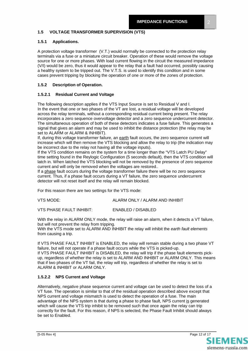
IMPEDANCE FUNCTIONS 2 1 DISTANCE PROTECTION FUNCTIONS 1.1 CROSS-POLARISED MHO It is fundamental to the requirements of discrimination that distance protection Zone 1 and 2 measuring characteristics for direct tripping are directional since they are required to detect faults in the forward direction only. As with any measuring device, operation on, or very close to, the boundary of operation will be less decisive than that further inside the characteristic. It can be seen that the characteristic for Zones 1 and 2 pass through the origin, and thus, faults occurring very close to the relaying point will represent a boundary condition. In order to improve the operating speed, and to ensure correct directional response for such faults, a method known as cross-polarising is used. A proportion (30%) of the voltage measured on a phase (or phases) not involved in the fault is added to the fault voltage used by the comparator (after being shifted 90º to bring it into phase with the fault voltage). The polarising voltage used will be different for each fault comparator, i.e. red-earth for a yellow-blue fault, red-blue for a yellow earth fault. For balanced (three-phase) faults the voltage in each phase will be equal, and so this will have no effect. For unbalanced faults, however, this ”cross-polarising” changes the overall shape of the characteristic into a circle of diameter Z kZF S− as shown in figure 1, when the current is flowing in the forward direction. It can be seen from this diagram that the reach along the line angle is unaffected, but off angle, the characteristic expands. This expansion gives an increasing coverage of the resistive axis, and allows detection of higher resistance faults than the unpolarised mho characteristics. The healthy phase voltage, and thus the degree of expansion will depend largely on the source impedance, and thus the shape of the characteristic will depend upon the System Impedance Ratio (SIR). The higher the SIR, the greater the expansion. When current flow is in the reverse direction, the shape of the characteristic will change again to give a small circle of operation in the forward direction (i.e. in the opposite direction from the fault). This ensures the stability of the relay for close-up reverse faults. This expansion will only apply for unbalanced conditions. Some models of the relay employ a feature known as Voltage Memory. This provides a polarising vector derived from the pre-fault voltage which is applied for a limited time, after which the protection is inhibited. This provides a similar expansion for three-phase faults. Full details about voltage memory are provided under a separate heading, for models in which it is applied.
Characteristic underunbalanced fault conditions
Characteristic underbalanced fault conditions
Characteristic for forward power flow Characteristic for reverse power flow
Z -kZF S
ZF
kZS
kZS
ZF
Z -kZF S
Figure 1, Cross-Polarised Mho Characteristic

[5-05 Rev 4] Page 3 of 17
IMPEDANCE FUNCTIONS 2 1.1.1 OFFSET MHO CHARACTERISTIC The offset Mho characteristic is shown in figure 2. The characteristic is set with a forward reach,
ZF and a reverse reach, ZR. This type of characteristic may be selected for Zone 3, and it provides time delayed back-up for faults behind the relaying point. In addition to this, the origin is not a boundary condition as it is for zones 1 and 2, so the offset zone can be used in schemes to provide positive operation for marginal conditions (see Switch-onto-fault logic).
1.1.2 FAULT CONFIGURATION A distance relay must measure the impedance correctly for all types of power system faults (single-phase, two-phase and three phase). For each fault type the effective impedance at the relaying point will be different because the path that the current takes will be different in each case, as illustrated in figure 3 below ;
To correctly measure the impedance to the fault point, the correct current and voltage must be applied to the relay. The relay impedance setting is made in terms of the positive sequence
Distance Relay
F
Total Line Impedance, ZL
ZS ZL1 ZL-ZL1
Earth Return Path, Z0
Remote End
Distance Relay
ZS ZL1
Earth Return Path, Z0
ZS ZL1
Earth Return Path, Z0
ZS ZL1
Earth Return Path, Z0
(ii) Single Phase Fault
(iii) Double Phase Fault
(iv) Three - Phase Fault (i) System Diagram
Figure 3 System Fault Conditions
ZR
ZF
Z
Z-ZF
Z-ZR
Figure 2 Offset Mho Characteristic

[5-05 Rev 4] Page 4 of 17
IMPEDANCE FUNCTIONS 2 impedance to the point of reach which means that the relay setting is the same for all types of fault. The Ohmega relay uses discrete measuring elements for each fault type in each zone. The quantities measured by each of these element s are described in the following sections. 1.1.2.1 Phase Faults
There are three phase fault elements in each zone looking at red-yellow, yellow-blue, and blue-red phase faults respectively. These elements measure the phase-phase voltage, and phase-phase current for their particuar phases. As can be seen from figure 4, this leads to a loop impedance of 2ZL.
1.1.2.2 Earth Faults
When considering earth faults, the relay is actually presented with a loop impedance of ZL + ZN, where ZL is the impedance in the line to the fault and ZN is the earth return path, as shown in figure 5. This can also be compensated for by using a combination of the current flowing in the line and neutral circuit but the problem is that the complex impedance ZN is not known and is not readily available by measurement.
Conventionally the known parameter available for the line is the zero sequence impedance. (If it is not known, it can be measured for any particular line). The zero sequence impedance, like the positive sequence impedance is proportional to the line length
Figure 6 shows the method utilised to measure the zero sequence impedance of a line that gives the expression.;
+= NZZZo
33 1
or 3
)( 1ZZZ ON
−=
and the ratio
−= 1
31
11 ZZ
ZZ ON
11
131 Z
ZZ
Z ON
−=
hence ZN = K0Z1
VPh-Ph IPh-Ph
ZL1
ZL1
Figure 4 Fault Loop for Phase-Phase faults
VPh-E IPh-E
Earth Return Path, Z0
ZL1
Figure 5 Fault loop for earth faults
Z1
Zo = 3 x Measured loop
V Z1 Z1
ZN
Figure 6 Sequence impedance diagram for an earth fault

[5-05 Rev 4] Page 5 of 17
IMPEDANCE FUNCTIONS 2 where
−= 1
31
1ZZ
K OO
This is a convenient factor to use in the phase comparison logic as the actual value of Z0 is not required provided the ratio Z 0 / Z1 and the phase angles of Z0 and Z1 are available. The K0 factor described above must of course take into account the phase angles of Z1 and Z0 in the calculation for K0. The advantage of using the method described above is that the ratio Z0/Z1 is a relatively simple calculation and can be obtained using any convenient dimensions (eg Primary Ohms, Secondary Ohms, Ohms/Km etc) provided the zero phase sequence value and the positive phase sequence value are expressed in the same units. When the reach setting Z1, the ratio Z0 / Z11, the line angle, and the angle of Z0 are entered the relay calculates the composite value.
−= 1ZZ
31K
1
OO
and this value is taken into account for a polarised mho characteristic using the complex expression. IZ + K0 IN Z1 - V within 90° of V + Vp where I = Phase current Z1 = Positive phase sequence impedance of zone setting K0 = 1/3 (Z0/Z - 1) IN = Earth fault current V = Phase-earth fault voltage Vp = Polarising voltage 1.2 QUADRILATERAL CHARACTERISTIC In addition to MHO characteristics, some models of the relay have the option of quadrilateral characteristics for earth fault coverage. The quadrilateral characteristic can be set according to resistive coverage, reactive coverage and the line angle. The resistive cut off blinder is set to the same angle as the line angle. 1.2.1 CROSS-POLARISED QUADRILATERAL A typical polarised quadrilateral characteristic, as would be used for Zones 1 and 2, and the reverse looking Zone 4 is shown below. This characteristic is constructed using two directional characteristics (hence the need for polarising), a reactance characteristic and a resistance characteristic.
X
R
Resistance
Reactance
Directional
Directional
Figure 8 Forward-looking Quadrilateral Characteristic.

[5-05 Rev 4] Page 6 of 17
IMPEDANCE FUNCTIONS 2 Because of the polarising quantities, the directional lines will exhibit a shift toward the source during unbalanced faults, ensuring operation for close up forward faults, and stability for close up reverse faults. A self-polarised directional characteristic is given by the vector equation IZ VF ≡ Dividing through by I gives Z ZF ≡ In other words, we compare the angle of the fault impedance with the angle of the forward replica impedance, as shown below. If the two angles are within 90°, then the comparator operates, as shown in the diagram below;
Zf
Z
Operate
No Operation
R
X
Figure 9 Operating Zone of the directional element.
In order to obtain more reliable operation for close up fault conditions, the directional characteristic is polarised from a source other than the fault voltage, which will allow accurate determination of the fault direction for close-up faults. The vector equation for the polarised characteristic is; IZ VF P≡ The magnitude and angle of VP will depend on a combination of factors, but for unbalanced fault conditions it will be related to the source impedance ZS . For convenience the vector equation is Z ZF S≡ The characteristic is shown below;
Z f
Z
Z s
Z f
Z
Z s
Characteristic for forward power flow Characteristic for reverse power flow
Operation
No Operation
Operation
No Operation
Figure 10 Polarised Directional Characteristic

[5-05 Rev 4] Page 7 of 17
IMPEDANCE FUNCTIONS 2 As can be seen, the characteristic moves behind the origin for forward faults, and forward of it for reverse faults. In addition, as the SIR level increases (ZS increases relative to Z) the characteristic moves further from the origin. This ensures operation for close-up forward faults and stability for reverse faults. The Reactance Characteristic is shown in Figure 11, and consists of a straight line which cuts the reactive axis at a value XF . This requires a replica impedance ZF of magnitude XF Xsin Φ and angle Φ X . If the reactive component of the fault impedance is less than this value, the comparator operates. The angle Φ X is normally set at about -3° to the horizontal, so that the characteristic slopes in order to ensure that with increasing resistance, the relay will not overreach beyond setting. This angle is referred to as the reactive drop angle.
Zf
ZOperate
R
X
No Operation
Figure 11 Reactance Characteristic
The vector equation for the reactance characteristic is IZ V IZF F− ≡ which becomes Z Z ZF F− ≡ . If the angle between ZF and Z ZF − is less than 90°, the comparator will operate. The Resistive Characteristic is shown below, and is identical in nature to the reactance characteristic, except for the choice of replica impedance. This gives a characteristic which is inclined at the line angle, but crosses the resistive axis at a value RF , giving increased resistive coverage over the entire line length. The vector equation is again IZ V IZF F− ≡ which becomes Z Z ZF F− ≡ .
Zf
Z
Operate
R
X
Rf
No Operation
Figure 12 Resistance Characteristic
The replica impedance ZF has magnitude ( )RF Lcos Φ − 90 and angle Φ L − °90 .

[5-05 Rev 4] Page 8 of 17
IMPEDANCE FUNCTIONS 2 1.2.2 OFFSET QUADRILATERAL CHARACTERISTIC A typical offset quadrilateral characteristic is shown below. This is constructed using forward and reverse resistance characteristics, and forward and reverse reactance characteristics. This would be used for the offset zone 3 characteristic.
X
R
Resistance
Reactance
Resistance
Reactance
Figure 13 Typical offset quadrilateral distance characteristic

[5-05 Rev 4] Page 9 of 17
IMPEDANCE FUNCTIONS 2 1.3 IMPEDANCE ZONES The relay has three zones of protection as standard; zone 1 & 2 are polarised to operate in the forward direction while zone 3 can be set as either forward, reverse or as an offset zone. If the zone 3 is set as an offset zone then the minimum reverse reach is the same as the minimum forward reach. A fourth zone is available as an option in some models. This is a reverse-looking polarised characteristic. It is commonly used as a non-tripping zone in conjunction with a blocking scheme. The accuracy of the relay is ±5% or 0.1•, whichever is larger. The range for each of the impedance elements is from 0.1• to 250•, regardless of the output of the current transformers. Obviously, the settings used for 5A CTs will be smaller than those used for 1A CTs, on an equivalent circuit. With 5A CTs the minimum advisable setting is 0.1•. With 2A CTs the minimum advisable setting is 0.2 •. With 1A CTs the minimum advisable setting is 0.5•. For 2A and 1A, the settings can be reduced below these minimums, but the relay accuracy will be reduced.
[5-05 Rev 4] Page 10 of 17
IMPEDANCE FUNCTIONS 2 1.4 POWER SWING CHARACTERISTICS 1.4.1 Applications A power swing is the result of a change in angle between two power systems. Each system can be subjected to disturbances such as faults, loss of load, loss of large generation, etc. which in turn, may result in excursions of generator rotor angles. Assuming a two-machine model, one generator working at local end of the line will rotate with different angular velocity with reference to the remote generator until reaching a new stability point. This phenomenon can result in oscillating power between two ends of the protected line. At the relaying point, a distance element measures these as impedance oscillations which may encroach a set protection impedance characteristics and trip a line. In order to prevent from mal-tripping, a power swing blocking function may be implemented. There are various methods detecting power swings encroaching impedance measuring elements. The most common practice is to plot an impedance curve which encloses tripping impedance characteristics. “Ohmega” employs two independent shapes of characteristics for this purpose i.e. polygonal and circular.
It is possible to apply forward and reverse resistance blinders to the circular characteristic, to separate it from the load impedance if necessary. The user can enable or disable these blinders to achieve the best-tailored shape with reference to load and tripping zones.
The rectangular power swing detection characteristic (see Figure 15) is designed for use with quadrilateral characteristics – this is simply set in terms of forward and reverse reach (giving the reactive reach) and forward and reverse blinders (giving the resistive reach)
Load
Figure 14 Circular Power Swing Detection Zones
(i) Circular (ii) Circular Characteristic with Blinder Applied
PSD Inner Fwd Reach
PSD Inner Rev Reach
PSD Fwd Blinder
PSD Rev Blinder
Figure 15 Rectangular Power Swing Detection Zones
PSD Fwd Blinder PSD Rev Blinder
PSD Inner Fwd Reach
PSD Inner Rev Reach

[5-05 Rev 4] Page 11 of 17
IMPEDANCE FUNCTIONS 2 1.4.2 Description of Operation. 1.4.2.3 Power Swing Detection. The relay uses 2 zones of protection to detect a power swing condition, defined as the inner and the outer zones. Each of these zones consists of a phase to phase fault comparator applied to the Yellow-Blue phase. Upon operation of the outer zone, a timer is started. If the time between the operation of the outer zone and the inner zone is greater than the relay PSD Transit time, the relay will raise the power swing alarm. The reach of the power swing detection zones are set in terms of impedance for the inner reach. The outer reach is then set by a multiplying factor, usually 1.5 times the inner reach. ZPSB(Outer) = k. ZPSB(Inner) The inner reach should be either equal to or just above the furthest reach setting of the relay, so that all zones of the relay are contained completely within the inner power swing detection zone. A check should also be made on the outer reach with reference to the maximum feeder load. The outer reach should not encroach upon the load condition under any circumstances. This check is best carried out by inspection – if necessary sketching out the characterstics to ensure correct co-ordination. The blinders can be applied to prevent load encroachment if this is a possible problem. 1.4.2.4 Power Swing Blocking. Once a power swing has been detected it is often desirable to prevent operation of the relay during a power swing condition. The relay can be set to block operation of any combination of protection zones within the relay. Faults can occur during power oscillations, so it is necessary to provide a mean of distinguishing between a power swing and a genuine fault condition. Because a power swing condition is always a balanced three-phase condition, the relay can use the level of negative phase sequence current on the system to determine between these two conditions. Under balanced conditions, an untransposed transmission system can produce negative phase sequence currents of up to 14% of positive phase sequence current. Under fault conditions, however, the level of negative sequence current will be much higher. Thus, when the negative sequence current exceeds 25% of the positive sequence current, the power swing blocking will be removed, allowing the relay to operate. 1.4.3 Settings.
Power Swing detector ENABLE/ DISABLE PSD Zone Blocking _ _ _ _ PSD Shape CIRCULAR, RECTANGULAR PSD Blinders ENABLE / DISABLE Inner Forward Impedance 0.1-250 ohm in 0.1 ohm step Inner Reverse Impedance 0.1-250 ohm in 0.1 ohm step Inner Blinder Forward 0.1-250 ohm in 0.1 ohm step Inner Blinder Reverse 0.1-250 ohm in 0.1 ohm step Multiple (Outer Impedance) 1.05-250% in 0.01% step PS Timer 0-1000ms in 5ms step
Status Inputs: N/A Relay Outputs: POWER SWING ALARM
[5-05 Rev 4] Page 12 of 17
IMPEDANCE FUNCTIONS 2 1.5 VOLTAGE TRANSFORMER SUPERVISION (VTS) 1.5.1 Applications. A protection voltage transformer (V.T.) would normally be connected to the protection relay terminals via a fuse or a miniature circuit breaker. Operation of these would remove the voltage source for one or more phases. With load current flowing in the circuit the measured impedance (V/I) would be zero, thus it would appear to the relay that a fault had occurred, possibly causing a healthy system to be tripped out. The V.T.S. is used to identify this condition and in some cases prevent tripping by blocking the operation of one or more of the zones of protection. 1.5.2 Description of Operation. 1.5.2.1 Residual Current and Voltage The following description applies if the VTS Input Source is set to Residual V and I. In the event that one or two phases of the VT are lost, a residual voltage will be developed across the relay terminals, without a corresponding residual current being present. The relay incorporates a zero sequence overvoltage detector and a zero sequence undercurrent detector. The simultaneous operation of both of these detectors indicates a fuse failure. This generates a signal that gives an alarm and may be used to inhibit the distance protection (the relay may be set to ALARM or ALARM & INHIBIT). If, during this voltage transformer failure, an earth fault occurs, the zero sequence current will increase which will then remove the VTS blocking and allow the relay to trip (the indication may be incorrect due to the relay not having all the voltage inputs). If the VTS condition remains on the system for a time longer than the “VTS Latch PU Delay” time setting found in the Reylogic Configuration (5 seconds default), then the VTS condition will latch in. When latched the VTS blocking will not be removed by the presence of zero sequence current and will only be removed when the voltages are restored.. If a phase fault occurs during the voltage transformer failure there will be no zero sequence current. Thus, if a phase fault occurs during a VT failure, the zero sequence undercurrent detector will not reset itself and the relay will remain blocked. For this reason there are two settings for the VTS mode: VTS MODE: ALARM ONLY / ALARM AND INHIBIT VTS PHASE FAULT INHIBIT: ENABLED / DISABLED With the relay in ALARM ONLY mode, the relay will raise an alarm, when it detects a VT failure, but will not prevent the relay from tripping. With the VTS mode set to ALARM AND INHIBIT the relay will inhibit the earth fault elements from causing a trip. If VTS PHASE FAULT INHIBIT is ENABLED, the relay will remain stable during a two phase VT failure, but will not operate if a phase fault occurs while the VTS is picked-up. If VTS PHASE FAULT INHIBIT is DISABLED, the relay will trip if the phase fault elements pick-up, regardless of whether the relay is set to ALARM AND INHIBIT or ALARM ONLY. This means that if two phases of the VT fail, the relay will trip, regardless of whether the relay is set to ALARM & INHIBIT or ALARM ONLY. 1.5.2.2 NPS Current and Voltage Alternatively, negative phase sequence current and voltage can be used to detect the loss of a VT fuse. The operation is similar to that of the residual operation described above except that NPS current and voltage mismatch is used to detect the operation of a fuse. The main advantage of the NPS system is that during a phase to phase fault, NPS current is generated which will cause the VTS trip inhibit to be removed such that once again the relay can trip correctly for the fault. For this reason, if NPS is selected, the Phase Fault Inhibit should always be set to Enabled.

[5-05 Rev 4] Page 13 of 17
IMPEDANCE FUNCTIONS 2 The NPS settings are scaled such that they are equivalent to the Residual settings i.e. the voltage setting Vop = 3V0 for Residual or 3V2 for NPS. 1.5.3 General Operation This arrangement is relatively simple and readily lends itself to application assessment in terms of its effect, if any, on the earth fault protection coverage. The minimum time response is arranged to be approximately 2/3 of the minimum operating time of the zone 1 to ensure an adequate time margin for blocking. The inhibit signal is available immediately whereas the alarm signal has a time delay, which can be set from 0-60000ms to prevent nuisance alarms occurring during circuit breaker switching. The above principle is recommended in applications for the transmission and sub-transmission system where the maximum residual current is 5% or less of the load current. VTS ALARM contacts can be selected from the OUTPUT MENU. Where an MCB is used rather than Fuses, the loss of all three-phases of the VT can be detected by connecting a contact from the MCB to the VT CCTS ISOLATED Status Input of the relay. This will energise the Status Input when the VT MCB trips. 1.5.4 Settings.
VT Supervision VTS Mode VTS Latched Operation
Disable, Enable Alarm Only / Alarm & Inhibit Disable, Enable
VTS Phase Fault Inhibit VTS Input Source
Disable, Enable Res V&I/NPS V&I
VTS Ires Level 0.05..2 (0.3 X In) VTS Vop Level 1..100 (20) VTS Latch PU delay VTS Alarm PU delay
0..60000 (5000) 0..60000 (100)
Status Inputs: VT CCTS ISOLATED Relay Outputs: VTS ALARM

[5-05 Rev 4] Page 14 of 17
IMPEDANCE FUNCTIONS 2 1.6 SWITCH ON TO FAULT (SOTF) 1.6.1 Applications The Zone 1 instantaneous elements of the OHMEGA distance protection are directional and rely upon polarisation from either the faulted phase and/or a healthy phase. When closing on to a bolted fault where all three-phase voltages are extremely low, the Zone 1 instantaneous elements may not operate. Time delayed operation would occur from either the Zone 3 offset element or the High Set Overcurrent. This is not acceptable and special precautions are necessary to ensure high-speed clearance for this condition. The Switch-On-To-Fault feature ensures that for a short period of time after a CB is closed, the offset Zone 3 elements and the Overcurrent elements are allowed to trip at high speed. 1.6.2 Description of Operation The mode of Switch-on-to-fault logic required can be selected as either AC SOTF or DC SOTF. AC SOTF utilises three-phase pole dead logic, based on measured current (i.e. an AC quantity), to determine the circuit breaker status. The DC SOTF uses an auxiliary contact (i.e. a DC quantity) on the CB closing handle to determine when the CB is being closed. The SOTF output is automatically configured to operate the three-phase trip output. The LCTRIP can be mapped to one of the LED’s and to any of the output contacts to give an alarm. 1.6.2.3 AC SOTF The AC SOTF logic monitors the line current and voltage, and so it can only be used where the instrument transformers are placed on the line side of the circuit breaker. When the relay detects that the voltage and current are dead (i.e. voltage below 20% of the nominal, current below the SOTF O/C Operate Level) on all three phases, this will start the ACSOTFTIMER. This timer has a settable delay on pickup (the AC SOTF Pickup Delay) which is used to ensure that the circuit breaker has been switched out for maintenance. This delay is set by default to 10,000ms, so the breaker must have been open for at least ten seconds before the SOTF logic is initiated. Once the logic has been initiated the relay can cause a SOTF trip in one of two ways;
1. If the measured current rises above the SOTF O/C Operate Level while the measured voltage remains below 20% of the nominal voltage, the Relay will trip instantaneously if the Zone 3 starter picks up. Once the measured voltage has increased above 20% of the nominal voltage, the ACSOTFTIMER will reset after a fixed time delay of 200ms and the Zone 3 starter will no longer cause an instantaneous trip.
2. If the measured current rises above the SOTF O/C Operate Level while the measured
voltage remains below 20% of the nominal voltage, the Relay will trip after a fixed 25ms time delay. This delay is to prevent operation due to a race condition between the voltage and current reaching the “live” levels. Once the measured voltage has increased above 20% of the nominal voltage, the SOTF Overcurrent tripping criteria is removed instantaneously. This prevents the relay from tripping for high line charging currents.
This Overcurrent criterion is essential when a uni-directional Zone 3 is being used (i.e. not offset). In this case the zone 3 element will suffer from the same difficulties as Zones 1 and 2.
1.6.2.4 DC SOTF The DC SOTF logic works in much the same way as the AC SOTF, but has been specifically designed for situations where the VTs are mounted on the busbar side of the line circuit breaker. This means that the voltage input to the relay cannot be used to supervise the position of the breaker.

[5-05 Rev 4] Page 15 of 17
IMPEDANCE FUNCTIONS 2 A Status Input defined as DC SOTF Manual Close is connected to the Manual Close handle of the circuit breaker. This Status Input is triggered on the rising edge of the Manual Close signal, and for 400 ms after this signal the relay will allow instantaneous tripping of the Zone 3 element. A longer time delay is used for the DC SOTF logic (400ms rather than 200ms) because it needs to incorporate the closing time for the circuit breaker. 1.6.3 Settings The settings menu for the SOTF function is contained in the AUX PROTECTION Menu and contains the following settings:
Switch On To Fault Disable / Enable SOTF Mode AC SOTF / DC SOTF SOTF O/C Operate Level 0.3..4 (0.3xIn) AC SOTF Pickup Delay 10000ms
Status Inputs: DC SOTF MANUAL CLOSE Relay Outputs: SOTF OPERATED
[5-05 Rev 4] Page 16 of 17
IMPEDANCE FUNCTIONS 2 2 AUXILIARY FUNCTIONS 2.1 FAULT LOCATOR 2.1.1 Applications The fault locator gives the operator an indication of the location of the fault. This information can be presented in three different formats which are a percentage of line length, or the distance in either miles or kilometres. This is selected in the menu function. 2.1.2 Description of Operation The fault locator is programmed with the Positive Sequence Line Impedance. It is important that this value must be for the total length of the feeder and not the Zone 1 reach. The values must be in terms of secondary impedance. The secondary impedance per unit must also be entered. For example a 20km line may have a secondary impedance of 15 ohms. This would give a unit value of 0.75 ohms per kilometre using these values the fault locator would accurately measure the fault position. The fault locator if enabled will measure for any general trip condition. While the fault is being calculated the relay fascia function keys are disabled for a few seconds. 2.1.3 Relay Settings
Fault Locator Disable / Enable Pos Seq Line Impedance 0.1 .. 250 (10) Sec’y Z+ per unit distance 0.001..5 (0.5) Display Distance as Percent / Miles / Kilometres
Status Inputs: N/A Relay Outputs: N/A 2.2 TRIP CIRCUIT SUPERVISION 2.2.1 Description of Operation The Ohmega relay can monitor it’s own trip circuit by assigning status inputs to Trip Cct 1, Trip Cct 2 & Trip Cct 3 (one for each of the three phases), Indication is then given instantaneously of trip circuit failure, should a fault be detected. The external connections for this feature are shown in Section 12. 2.2.2 Relay Settings Status Inputs: TRIP CCT Fail Relay Outputs: TRIP CCT Fail
[5-05 Rev 4] Page 17 of 17
IMPEDANCE FUNCTIONS 2 2.3 HIGH SET OVERCURRENT 2.3.1 Description of Operation This is simply a DTL overcurrent element which works in parallel with the distance protection. Operation of this overcurrent element will result in a main distance trip. 2.3.2 Relay Settings
High Set Disable / Enable HS Level 0.1-35 x In (4x) HS Time Delay 0..60000ms (0)
Status Inputs: N/A Relay Outputs: HIGH SET

![Chapter 308-93 WAC - Legislature Homeleg.wa.gov/CodeReviser/WACArchive/Documents/2012/WAC-308-93... · (5/11/10) [Ch. 308-93 WAC—p. 1] Chapter 308-93 Chapter 308-93 WAC VESSEL REGISTRATION](https://img.pdfslide.us/doc/110x75/5b99bc9a09d3f29c338cd7cb/chapter-308-93-wac-legislature-51110-ch-308-93-wacp-1-chapter-308-93.jpg)