Embed Size (px)
Citation preview
7/30/2019 7.Lubrication System
http://slidepdf.com/reader/full/7lubrication-system 1/36
LUBRICATION SYSTEM
1
7/30/2019 7.Lubrication System
http://slidepdf.com/reader/full/7lubrication-system 2/36
Introduction
In engines, frictional losses are mainly due to sliding as
well as rotating parts
Engine friction is expressed in terms of frictional power
fp=ip-bp
Frictional losses is mainly attributed to the following
mechanical losses
Direct frictional losses
Pumping losses
Power loss to drive the components to change and scavenge
Power loss to drive other auxiliary components
2
7/30/2019 7.Lubrication System
http://slidepdf.com/reader/full/7lubrication-system 3/36
Introduction
A good engine design should not the total frictional losses to
be more than 30% of energy input in reciprocating engine
It should be the aim of a good designer to reduce frictionand wear of the parts subjected to relative motion
This is achieved by proper lubrication system
3
7/30/2019 7.Lubrication System
http://slidepdf.com/reader/full/7lubrication-system 4/36
Direct Frictional Losses
It is the power absorbed due to the relative motion of
different bearing surfaces such as
piston rings,
main bearings,
cam shaft bearings etc…
The frictional losses are comparatively higher in
reciprocating engine
4
7/30/2019 7.Lubrication System
http://slidepdf.com/reader/full/7lubrication-system 5/36
Pumping Loss
For 4-stroke engines
Considerable amount of energy is spent during the exhaust
processes
The pumping loss is the net power spent by the engine (piston) on
the working medium (gases) during intake and exhaust strokes
For 2-stroke engines
this is negligible since the incoming fresh mixture is used to
scavenge the exhaust gases
5
7/30/2019 7.Lubrication System
http://slidepdf.com/reader/full/7lubrication-system 6/36
Power Loss to drive the components to change and
scavenge
4-stroke engine
In turbo/super charged engines the intake charge is supplied at a
higher pressure than the aspirated engines
For this purpose mechanically driven compressor or turbine driven
compressor us used accordingly the engine is called Supercharged
or turbocharged engine
These devices take away a part of engine output. This loss is
considered as negative frictional losses
2-stroke engine
With a scavenging pump, the power to drive the pump is supplied
by the engine
6
7/30/2019 7.Lubrication System
http://slidepdf.com/reader/full/7lubrication-system 7/36
Power loss to drive other auxiliary components
A good percentage of the generated power output
is spent to drive auxiliaries such as
Water pump Lubricating oil pump
Fuel pump
Cooling fanGenerator etc…
7
7/30/2019 7.Lubrication System
http://slidepdf.com/reader/full/7lubrication-system 8/36
Mechanical Efficiency
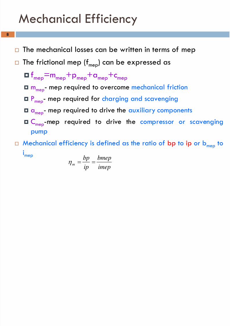
The mechanical losses can be written in terms of mep
The frictional mep (fmep) can be expressed as
fmep
=mmep
+pmep
+amep
+cmep
mmep- mep required to overcome mechanical friction
Pmep- mep required for charging and scavenging
amep- mep required to drive the auxiliary components
Cmep-mep required to drive the compressor or scavengingpump
Mechanical efficiency is defined as the ratio of bp to ip or bmep to
imep
imepbmep
ipbpm ==η
8
7/30/2019 7.Lubrication System
http://slidepdf.com/reader/full/7lubrication-system 9/36
Mechanical Friction
Friction losses comes into picture in the bearing surfaces of the
engine components due to their relative motion
Mechanical friction in engine may be divided in to 6 classes
Fluid-film or Hydrodynamic Friction
Partial-film Friction
Rolling Friction
Dry friction
Journal bearing friction
Friction due to piston motion
9
7/30/2019 7.Lubrication System
http://slidepdf.com/reader/full/7lubrication-system 10/36
Mechanical Friction
Friction due to Piston Motion
Friction due to the motion of the piston can be divided in
to
Viscous friction due to piston
Non-viscous friction due to piston ring
The non-viscous piston ring friction can be further
subdivided in to
Friction due to ring tension
Friction due to gas pressure behind the ring
10
7/30/2019 7.Lubrication System
http://slidepdf.com/reader/full/7lubrication-system 11/36
Blowby Losses
It is the phenomenon of leakage of combustion products
(gases) from the cylinder to the crankcase past the piston
and piston rings
It depends on the
Compression ratio
Inlet pressure
The condition of the piston rings
In the case of worn out piston rings this loss is more
This loss is usually accounted in the overall frictional losses
11
7/30/2019 7.Lubrication System
http://slidepdf.com/reader/full/7lubrication-system 12/36
Blowdown Loss
To reduce the work spent by the piston to drive out the exhaust gases the
exhaust valve is made to open before piston reaches BDC on its
expansion stroke
During this period the combustion gases rush out of cylinder due to
pressure difference
BeCoz of this there is a certain loss of power induced. This loss is called
the blowdown loss
This loss mainly depend on The exhaust valve timing and size
With large valve area and earlier exhaust valve opening, the blowdown loss
will be higher whereas with increasing in speed this loss tends to be lower
12
7/30/2019 7.Lubrication System
http://slidepdf.com/reader/full/7lubrication-system 13/36
Factors affecting Mechanical Friction
Various factors affecting the engine friction
Engine Design
Stroke-bore Ratio
Effect of Engine Size Piston Rings
Compression Ratio
Journal bearings
Engine Speed
Engine load
Cooling water temperature
Oil viscosity
13
7/30/2019 7.Lubrication System
http://slidepdf.com/reader/full/7lubrication-system 14/36
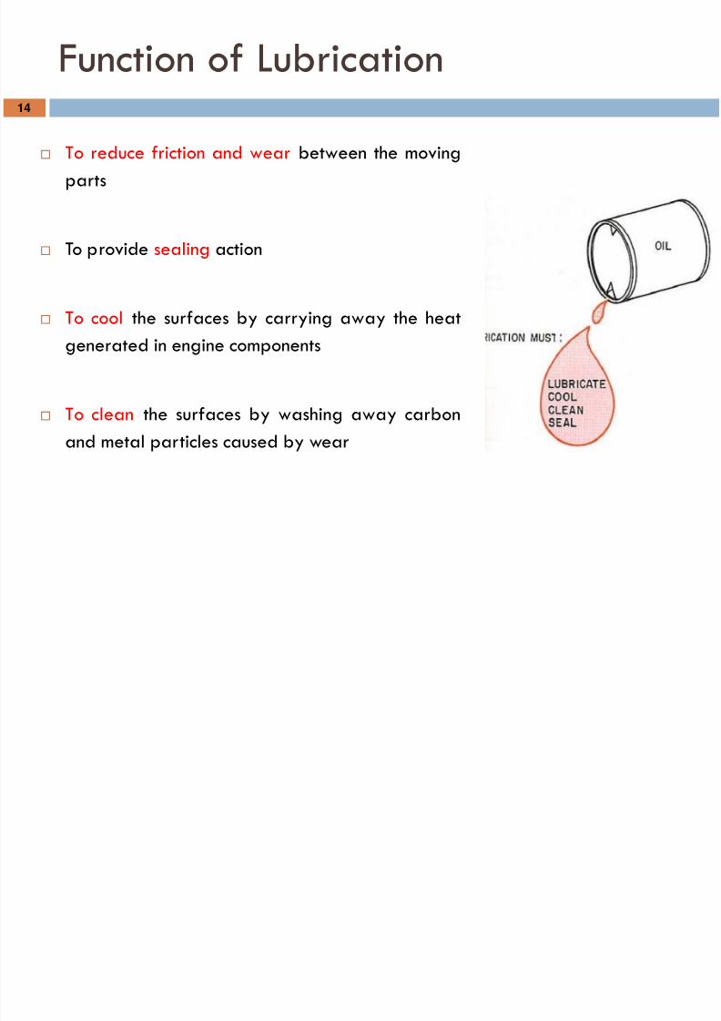
Function of Lubrication
To reduce friction and wear between the moving
parts
To provide sealing action
To cool the surfaces by carrying away the heat
generated in engine components
To clean the surfaces by washing away carbon
and metal particles caused by wear
14
7/30/2019 7.Lubrication System
http://slidepdf.com/reader/full/7lubrication-system 15/36
Lubrication System
The function of Lubrication system
Is to provide sufficient quantity of cooled & filtered oil
to give +ve and adequate lubrication to all the moving
parts
The various lubrication system used for IC engine
Mist Lubrication
Wet sump Lubrication
Dry sump Lubrication
15
7/30/2019 7.Lubrication System
http://slidepdf.com/reader/full/7lubrication-system 16/36
Mist Lubrication System
This system is used where crankcase lubrication is not suitable
In 2-stroke engine as the charge is compressed in the
crankcase, it is not possible to have the lubricating oil in the
sump In such engines the lubricating oil is mixed with the fuel, the
usual ratio being 3% to 6%
The oil and the fuel induced through the carburetor the fuel is
vaporized and the oil is in the form of mist goes via the
crankcase in to the cylinder
16
7/30/2019 7.Lubrication System
http://slidepdf.com/reader/full/7lubrication-system 17/36
Mist Lubrication System
Advantage of this system
simplicity,
low cost (does not required oil pump, filter)
Disadvantages
Causes heavy exhaust smoke
Get contaminated with acids and result in the corrosion of bearings
surface
Calls for through mixing for effective lubrication (this requires either
separate mixing prior to use of some additive to give the oil good mixing
characteristics)
The engine will suffer from insufficient lubrication as the supply of fuel is
less
17
7/30/2019 7.Lubrication System
http://slidepdf.com/reader/full/7lubrication-system 18/36
Wet Sump lubrication System
The bottom of the crankcase contains an oil pan or sump from
which the lubricating oil is pumped to various components by a
pump
After lubricating the parts the oil flows back to the sump by gravity
There are 3 varieties in wet sump lubricating system
The splash system
The splash and pressure system
The pressure feed system
18
7/30/2019 7.Lubrication System
http://slidepdf.com/reader/full/7lubrication-system 19/36
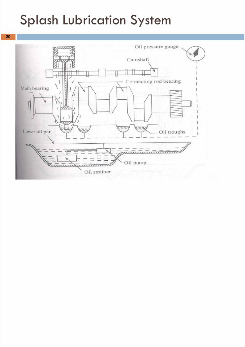
Splash System
This type of lubrication system is used in light duty engines.
The lubricating oil charged into the bottom of the crankcase and
maintained at predetermined level.
The oil is drawn by a pump and delivered through a distributing
pipe in to the splash troughs
A splasher or dipper is provided under each connecting road cap
19
7/30/2019 7.Lubrication System
http://slidepdf.com/reader/full/7lubrication-system 20/36
Splash Lubrication System20
7/30/2019 7.Lubrication System
http://slidepdf.com/reader/full/7lubrication-system 21/36
Splash & pressure lubrication system
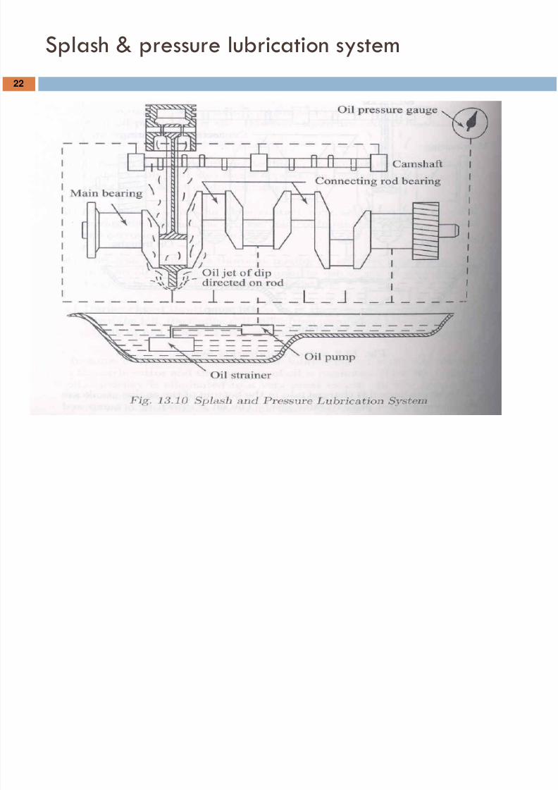
The lubricating oil is supplied under pressure to main and
camshaft bearings
The oil is also supplied under pressure to pipes which direct a
stream of oil against the dippers on the big end connecting rod
bearing cup
The crankpin bearings are lubricated by the splash or spray of
oil thrown up by dipper
21
7/30/2019 7.Lubrication System
http://slidepdf.com/reader/full/7lubrication-system 22/36
Splash & pressure lubrication system
22
7/30/2019 7.Lubrication System
http://slidepdf.com/reader/full/7lubrication-system 23/36
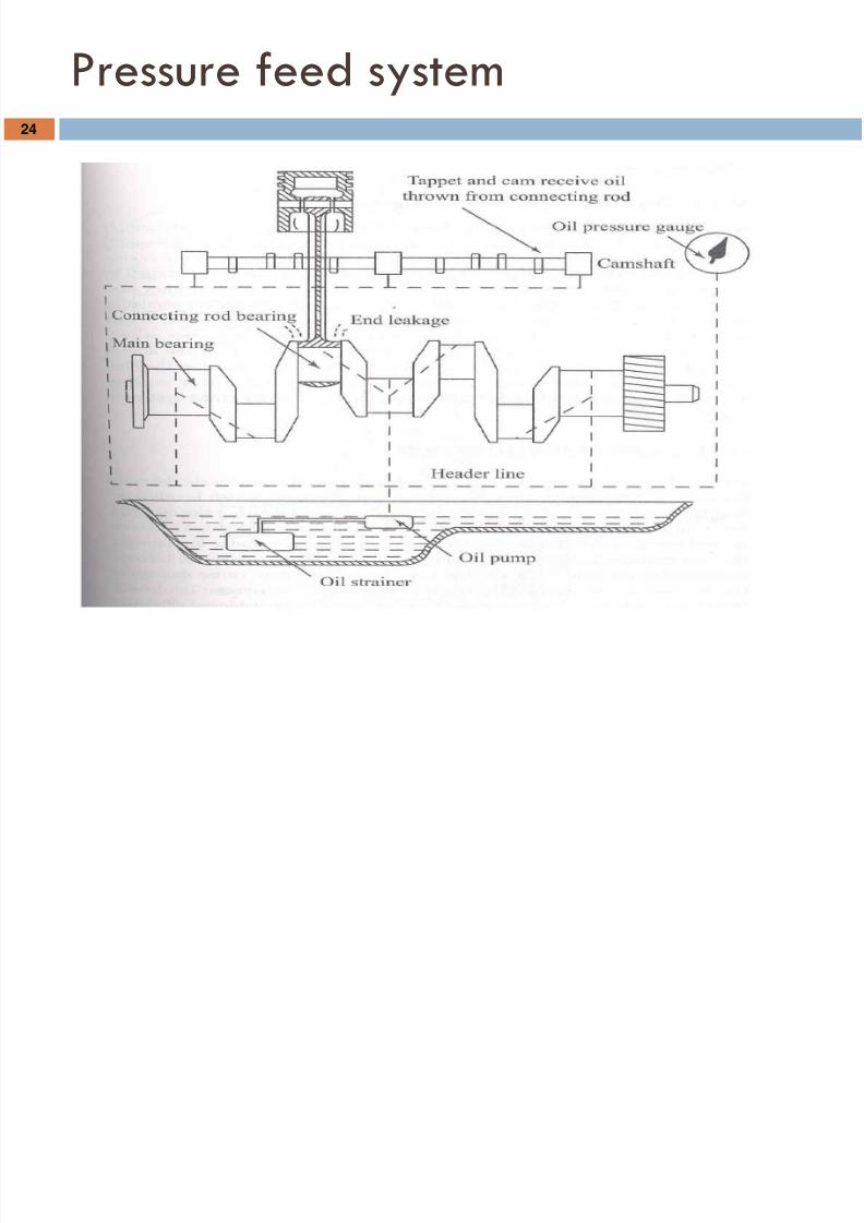
Pressure feed system
The oil is forced to all the main bearings of crankshaft
Pressure relief valve is fitted to maintain the predictable
pressure values
Oil hole is drilled from the center of each crankpin to the
center of an adjacent main journal through which oil can passfrom the main bearing to the crankpin
23
7/30/2019 7.Lubrication System
http://slidepdf.com/reader/full/7lubrication-system 24/36
Pressure feed system24
7/30/2019 7.Lubrication System
http://slidepdf.com/reader/full/7lubrication-system 25/36
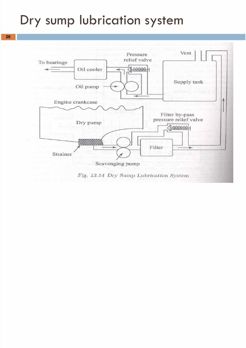
Dry sump lubrication system
In this system the oil is carried in an external tank
An oil pump draws oil from the supply tank and circulates it under pressure
to the various bearings of the engine
Oil dripping from the cylinders and bearings in to the sump is removed by
a scavenging pump which in turn the oil is passed through a filter and fed
back to the supply tank
The capacity of scavenging pump is always greater than the oil pump
A separate oil cooler provided to remove heat from the oil
25
7/30/2019 7.Lubrication System
http://slidepdf.com/reader/full/7lubrication-system 26/36
Dry sump lubrication system26
7/30/2019 7.Lubrication System
http://slidepdf.com/reader/full/7lubrication-system 27/36
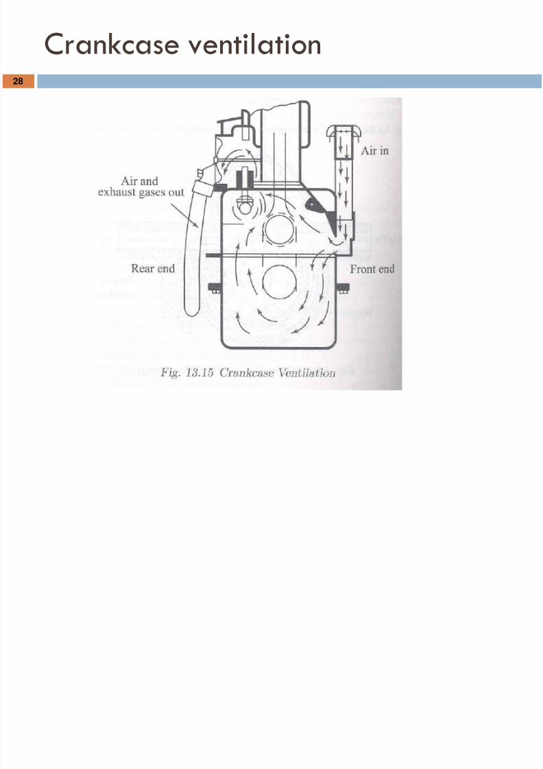
Crankcase ventilation
During the compression and expansion strokes the gas inside the cylinder getspast the piston rings and enters the crankcase which is called blow-by
It contains water vapor and sulfuric acid
If this contamination is appreciable amount it causes corrosion of steel parts
in the crankcase
This may also promote sludge formation in the lubricating oil
When the amount of water vapor condensed becomes considerable, in cold
weather this may freeze and may cause damage to the lubricating oil pump
27
7/30/2019 7.Lubrication System
http://slidepdf.com/reader/full/7lubrication-system 28/36
Crankcase ventilation28
7/30/2019 7.Lubrication System
http://slidepdf.com/reader/full/7lubrication-system 29/36
Crankcase ventilation
This removal of the blowby can be achieved effectively by passing aconstant stream of fresh air through the crankcase known as Crankcase
ventilation
By doing so not only all the water vapor but also a considerable proportionof fuel in the blow-by may be removed from the crank case.
The crankcase must have an air inlet and outlet for the effective crankcase
ventilation
It is possible to connect the crankcase outlet to the air cleaner, where the
inlet suction serves to ventilate the crankcase and unburned fuel, gases as
well as the water vapor are then drawn in to the cylinder where the fuels
has another chance to burn
29
7/30/2019 7.Lubrication System
http://slidepdf.com/reader/full/7lubrication-system 30/36
Lubricants
Classification of Lubricant
Animal
Vegetable
Mineral Synthetic
30
7/30/2019 7.Lubrication System
http://slidepdf.com/reader/full/7lubrication-system 31/36
Animal Lubricants
Lubricants with animal origin:
Tallow
Tallow oil
Lard oil
Neat’s foot oi
Porpoise oil
These are highly stable at normal temperatures Animal lubricants may not be used for internal combustion
because they produce fatty acids.
31
7/30/2019 7.Lubrication System
http://slidepdf.com/reader/full/7lubrication-system 32/36
Vegetable Lubricants
Examples of vegetable lubricants are:
Castor oil
Olive oil
Cottonseed oil
Animal and vegetable oils have a lower coefficient
of friction than most mineral oils but they rapidly
wear away steel
32
7/30/2019 7.Lubrication System
http://slidepdf.com/reader/full/7lubrication-system 33/36
Mineral Lubricants
These lubricants are used to a large extent in the
lubrication of internal combustion engines
There are three classifications of mineral lubricants:
Solid
Semisolid Fluid
33
7/30/2019 7.Lubrication System
http://slidepdf.com/reader/full/7lubrication-system 34/36
Synthetic Lubricants
Because of the high operating temperatures of engines, it became
necessary to develop lubricants which would retain their characteristics at
temperatures that cause petroleum lubricants to evaporate and break
down
Synthetic lubricants do not break down easily and do not produce coke or
other deposits
34
7/30/2019 7.Lubrication System
http://slidepdf.com/reader/full/7lubrication-system 35/36
Lubricating Oil Properties
Gravity
Flash Point
Viscosity
Cloud Point
Pour Point
Carbon-Residue Test
Ash Test
Precipitation Number
Corrosion andNeutralization Number
Oiliness
Extreme-Pressure
(Hypoid) Lubricants Chemical and Physical
Stability
35
7/30/2019 7.Lubrication System
http://slidepdf.com/reader/full/7lubrication-system 36/36
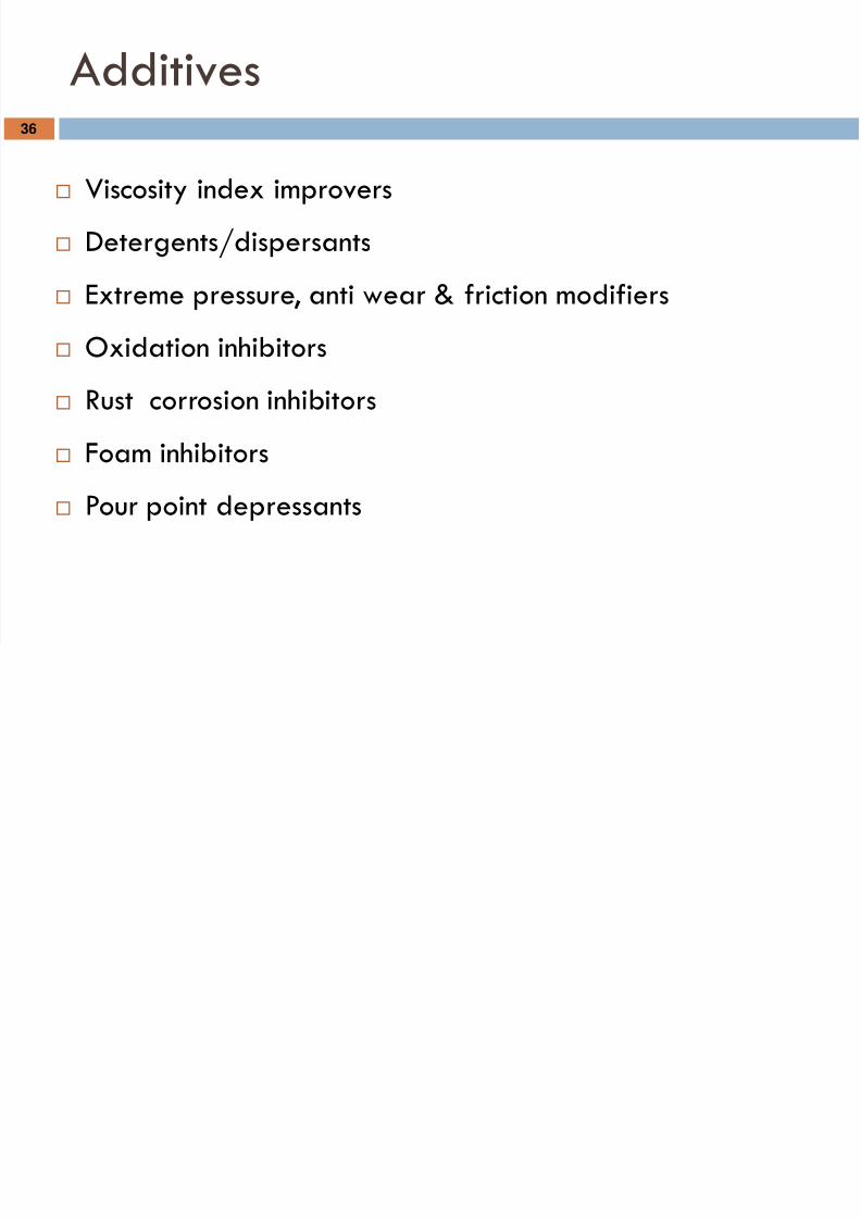
Additives
Viscosity index improvers
Detergents/dispersants
Extreme pressure, anti wear & friction modifiers Oxidation inhibitors
Rust corrosion inhibitors
Foam inhibitors Pour point depressants
36


![Lubrication System Caterpilar - Guide[1]](https://img.pdfslide.us/doc/110x75/577c7c701a28abe0549a999e/lubrication-system-caterpilar-guide1.jpg)