Embed Size (px)
Citation preview


___________________
___________________
___________________
___________________
___________________
___________________
___________________
___________________
___________________
PAC
Measuring Devices 7KT PAC1200 multichannel current measuring system
System Manual
11/2017 2514374103-03
Introduction 1
Safety notes 2
Product description 3
Connection 4
Operator control (software) 5
Service and maintenance 6
Technical data 7
Appendix A
ESD guidelines B

Siemens AG Division Energy Management Postfach 32 20 91050 ERLANGEN GERMANY
Document order number: 3ZW1012-0KT12-0AC1 Ⓟ 01/2018 Subject to change
Copyright © Siemens AG 2016. All rights reserved
Legal information Warning notice system
This manual contains notices you have to observe in order to ensure your personal safety, as well as to prevent damage to property. The notices referring to your personal safety are highlighted in the manual by a safety alert symbol, notices referring only to property damage have no safety alert symbol. These notices shown below are graded according to the degree of danger.
DANGER indicates that death or severe personal injury will result if proper precautions are not taken.
WARNING indicates that death or severe personal injury may result if proper precautions are not taken.
CAUTION indicates that minor personal injury can result if proper precautions are not taken.
NOTICE indicates that property damage can result if proper precautions are not taken.
If more than one degree of danger is present, the warning notice representing the highest degree of danger will be used. A notice warning of injury to persons with a safety alert symbol may also include a warning relating to property damage.
Qualified Personnel The product/system described in this documentation may be operated only by personnel qualified for the specific task in accordance with the relevant documentation, in particular its warning notices and safety instructions. Qualified personnel are those who, based on their training and experience, are capable of identifying risks and avoiding potential hazards when working with these products/systems.
Proper use of Siemens products Note the following:
WARNING Siemens products may only be used for the applications described in the catalog and in the relevant technical documentation. If products and components from other manufacturers are used, these must be recommended or approved by Siemens. Proper transport, storage, installation, assembly, commissioning, operation and maintenance are required to ensure that the products operate safely and without any problems. The permissible ambient conditions must be complied with. The information in the relevant documentation must be observed.
Trademarks All names identified by ® are registered trademarks of Siemens AG. The remaining trademarks in this publication may be trademarks whose use by third parties for their own purposes could violate the rights of the owner.
Disclaimer of Liability We have reviewed the contents of this publication to ensure consistency with the hardware and software described. Since variance cannot be precluded entirely, we cannot guarantee full consistency. However, the information in this publication is reviewed regularly and any necessary corrections are included in subsequent editions.
7KT PAC1200 multichannel current measuring system System Manual, 11/2017, 2514374103-03 3
Table of contents
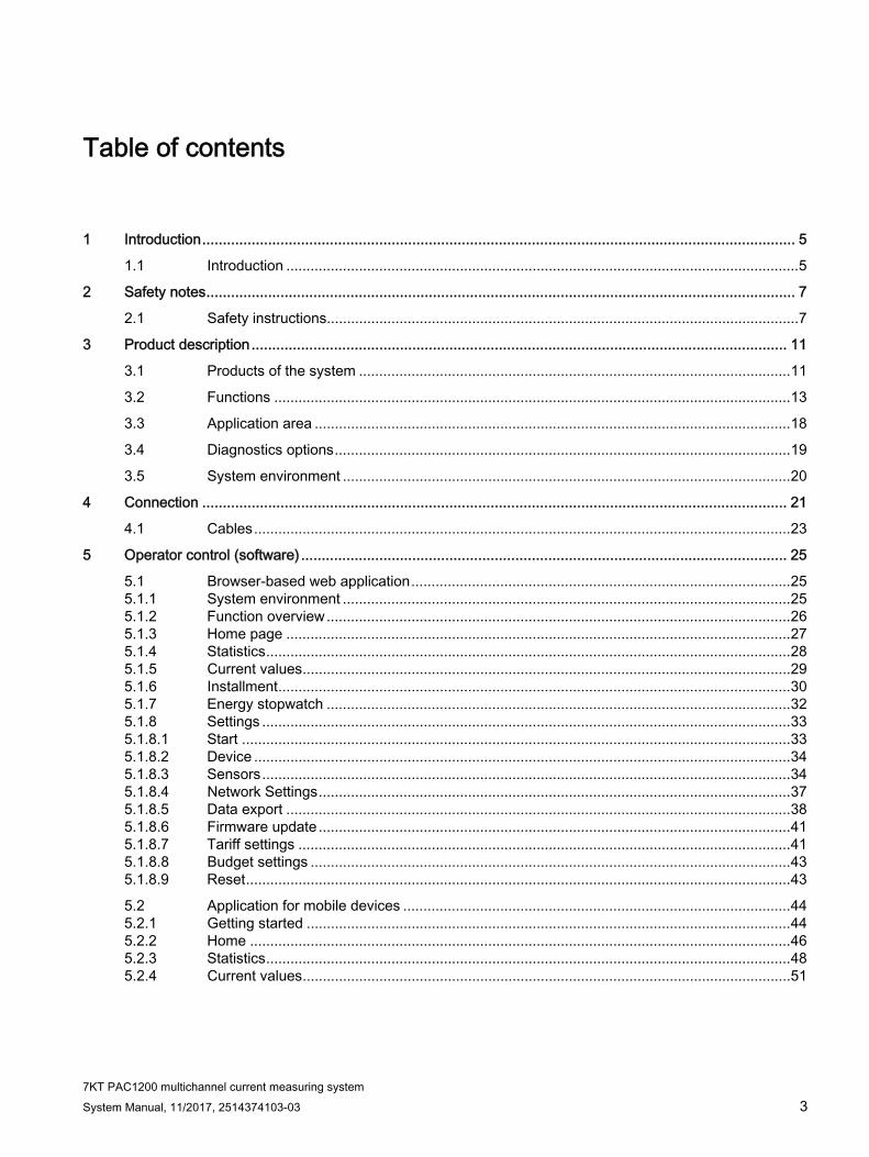
1 Introduction ................................................................................................................................................ 5
1.1 Introduction ............................................................................................................................... 5
2 Safety notes ............................................................................................................................................... 7
2.1 Safety instructions ..................................................................................................................... 7
3 Product description .................................................................................................................................. 11
3.1 Products of the system ........................................................................................................... 11
3.2 Functions ................................................................................................................................ 13
3.3 Application area ...................................................................................................................... 18
3.4 Diagnostics options ................................................................................................................. 19
3.5 System environment ............................................................................................................... 20
4 Connection .............................................................................................................................................. 21
4.1 Cables ..................................................................................................................................... 23
5 Operator control (software) ...................................................................................................................... 25
5.1 Browser-based web application .............................................................................................. 25 5.1.1 System environment ............................................................................................................... 25 5.1.2 Function overview ................................................................................................................... 26 5.1.3 Home page ............................................................................................................................. 27 5.1.4 Statistics .................................................................................................................................. 28 5.1.5 Current values ......................................................................................................................... 29 5.1.6 Installment ............................................................................................................................... 30 5.1.7 Energy stopwatch ................................................................................................................... 32 5.1.8 Settings ................................................................................................................................... 33 5.1.8.1 Start ........................................................................................................................................ 33 5.1.8.2 Device ..................................................................................................................................... 34 5.1.8.3 Sensors ................................................................................................................................... 34 5.1.8.4 Network Settings ..................................................................................................................... 37 5.1.8.5 Data export ............................................................................................................................. 38 5.1.8.6 Firmware update ..................................................................................................................... 41 5.1.8.7 Tariff settings .......................................................................................................................... 41 5.1.8.8 Budget settings ....................................................................................................................... 43 5.1.8.9 Reset ....................................................................................................................................... 43
5.2 Application for mobile devices ................................................................................................ 44 5.2.1 Getting started ........................................................................................................................ 44 5.2.2 Home ...................................................................................................................................... 46 5.2.3 Statistics .................................................................................................................................. 48 5.2.4 Current values ......................................................................................................................... 51

Table of contents
7KT PAC1200 multichannel current measuring system 4 System Manual, 11/2017, 2514374103-03
6 Service and maintenance ........................................................................................................................ 53
6.1 Error messages ...................................................................................................................... 53
6.2 Disposal ................................................................................................................................. 53
7 Technical data ......................................................................................................................................... 55
7.1 Dimension drawings ............................................................................................................... 58 7.1.1 Dimensions of the Data Manager .......................................................................................... 58 7.1.2 Dimensions of the sensor bar ................................................................................................ 59 7.1.3 Dimensions of the sensors on the sensor bar ....................................................................... 63
A Appendix .................................................................................................................................................. 65
A.1 FAQs ...................................................................................................................................... 65
A.2 Modbus register list ................................................................................................................ 66
A.3 Internal registers .................................................................................................................... 66
A.4 Sensor registers ..................................................................................................................... 77
B ESD guidelines ........................................................................................................................................ 79
B.1 Electrostatic sensitive devices (ESD) .................................................................................... 79
Glossary .................................................................................................................................................. 81
Index ........................................................................................................................................................ 83

7KT PAC1200 multichannel current measuring system System Manual, 11/2017, 2514374103-03 5
Introduction 11.1 Introduction
The component parts of the 7KT PAC1200 multichannel current measuring system are described in this document
● Data Manager
● Sensor bar
● Sensors
The configuration is also described via the web server.
Target group The tasks described in this document must only be carried out by persons with the following electrical
training/qualifications:
● Training in the installation und commissioning of electrical devices
● Training in electrical hazards and local safety regulations
● Knowledge of the relevant standards and guidelines
Further documents You can find further details in the following documents:
● Operating Instructions "7KT PAC1200 multichannel current measuring system"


7KT PAC1200 multichannel current measuring system System Manual, 11/2017, 2514374103-03 7
Safety notes 22.1 Safety instructions
The safety instructions that have to be followed when using the 7KT PAC1200 multichannel current measuring system are given below.
DANGER
Hazardous voltage. Will cause death or serious injury.
Turn off and lock out all power supplying this device before working on it. Installation and maintenance work on this device must by carried out by authorized persons with the appropriate electrical training only.
CAUTION
Damage to, or destruction of, the Data Manager. Material damage.
Observe the prescribed minimum clearances between the network cable and the installation components that carry mains voltage, or use suitable insulation.
Always lay the data and power lines separately or in separate pipelines. Observe EN 50174-2 here.
NOTICE
Overvoltage. Material damage.
If network cables are laid in the outdoor area, overvoltages can arise as a result of lightning strikes, for example.
The network cable must be safeguarded with suitable overvoltage protection.
NOTICE
Damage to the sensor bar through transient overvoltages. Material damage.
Install additional overvoltage arresters in accordance with SPD Type 1 (primary protection) und SPD Type 2 (medium protection) upstream of the Data Manager.
Ensure that the Data Manager that supplies the sensor bar with voltage can be disconnected, for example, with a miniature circuit breaker. This must be labeled as a circuit breaker for the Data Manager, and it must be easily accessible.

Safety notes 2.1 Safety instructions
7KT PAC1200 multichannel current measuring system 8 System Manual, 11/2017, 2514374103-03
NOTICE
Damage to, or destruction of, the Data Manager. Material damage.
Do not connect an ISDN cable to the Data Manager’s network connection.
Use the multichannel current measuring system in dry environments only and keep away from liquids.
Note
Install the multichannel current measuring system in the control cabinet only, and ensure that the connection areas for the line conductor and the neutral conductor are located behind a cover or touch protection barrier.
Do not operate the Data Manager beyond the limits specified in the technical data.
The enclosures or electrical distribution boards must only be accessible using a key or tool to restrict access to authorized personnel. Disconnect the electrical distribution board before installation work or maintenance work, and protect it from being unintentionally switched on again.
Note
You can find the open-source software included in this product, and the corresponding open-source software license conditions, in the Readme_OSS.
1. Please protect access to the interface by a password so that only authorized persons are able to access the Data Manager and change settings.
2. Supported protocols: Dynamic Host Configuration Protocol (DHCP) Universal Plug and Play (UPnP), Network Time Protocol (NTP), File Transfer Protocol (FTP), Simple File Transfer Protocol (SFTP), E-Mail, MODBUS TCP
Data Manager For safety reasons, it is forbidden to modify the product, including the software, or to install components that are not expressly recommended or marketed for this product.
Any use of the product other than the intended use described is considered improper use.
Impermissible modification, conversions, repairs, or opening of the product are forbidden. The enclosed documentation is a component part of the product and must be read, observed, and kept available at all times.
In accordance with its classification in Overvoltage category III, the Data Manager may only be connected in the subdistribution board or circuit distribution board on the load side downstream of the energy counter of the power supply company. It is suitable only for use in the indoor area, and it is approved for use in the member states of the EU. Use the sensor bar only in accordance with the information given in the enclosed documentation. Any other use can result in material damage and personal injury.

Safety notes 2.1 Safety instructions
7KT PAC1200 multichannel current measuring system System Manual, 11/2017, 2514374103-03 9
The Data Manager is not an electricity meter for active-power consumption in the sense of EU Directive 2004/22/EC (MID). It must only be used for internal accounting purposes. The data collected by the Data Manager about power generation in your plant can differ from the data of the main energy counter.
Sensor bar The sensor bar may only be operated when installed in the distribution box and the protective covers are in place. The sensor bar is approved for use in dry indoor areas only.
Use the sensor bar only in accordance with the information given in the enclosed documentation. Any other use can result in material damage and personal injury.
For safety reasons, changes to the sensor bar are forbidden unless expressly approved for the product by Siemens AG. Any use of the product other than the intended use described is considered improper use. Impermissible modification, conversions, repairs, or opening of the product are forbidden. The enclosed documentation is a component part of the product and must be read, observed, and kept available at all times.
CAUTION
Overvoltage. Material damage.
Only safety extra low voltages may be connected to the sensor bar.
Laws and directives The following standards apply for this system:
● EN 61010-1: 2010 Safety requirements for electrical equipment for measurement, control and laboratory use
● EN 61326-1: 2013 Electrical equipment for measurement, control and laboratory use - EMC requirements
● EN 60950-1:2006 + A11:2009 + A1:2010 Information technology equipment - Safety
● EN 50428:2005 + A1:2007 + A2:2009 Switches for household and similar fixed electrical installations
● EN 61000-3-2:2014 + A1:2009 + A2:2009 EMC - Part 3-2: Limit values for harmonic currents
● EN 6100-3-3:2013 EMC - Part 3-3: Limits - Limitation of voltage changes, voltage fluctuations and flicker in public low-voltage supply systems

7KT PAC1200 multichannel current measuring system System Manual, 11/2017, 2514374103-03 11
Product description 33.1 Products of the system
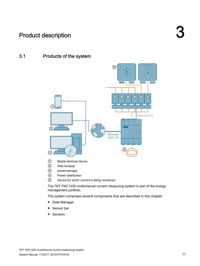
① Mobile terminal device② Web browser ③ powermanager ④ Power distribution ⑤ Device for which current is being monitored
The 7KT PAC1200 multichannel current measuring system is part of the energy management portfolio.
The system comprises several components that are described in this chapter:
● Data Manager
● Sensor bar
● Sensors

Product description 3.1 Products of the system
7KT PAC1200 multichannel current measuring system 12 System Manual, 11/2017, 2514374103-03
Highlights ● Fully integrated smart meter
● 3-phase active power and reactive power energy measurement
● Measurement of energy as balancing counter
● Direct connection up to 63 A
● Optional use with external measuring transformer for extending the measuring range (e.g. 100 ... 600 A)
● Standard rail mounting (4 MW)
● Operator input / configuration: Web interface
● Support of up to 96 sensors for single-phase measurement
Applications The 7KT PAC1200 multichannel current measuring system monitors and displays the energy consumption of up to 96 outgoing feeders. The Data Manager can supply up to eight sensor bars. The full configuration would thus be 8 sensor bars with 12 sensors each.
Value provided by the system The system makes energy consumption and the resulting costs transparent for a given installation.
The system can be adapted to individual needs and application scenarios. In addition, single sensors can be named individually and compared with each other.
The system can also be configured flexibly as the number of sensor bars can be varied.
Up to eight different, selectable consumption sources can be compared with each other.
The measured values can be displayed via a Web browser. Both current values and statistical values can be displayed here. Display is possible in an application for mobile terminal devices, as a desktop application, or in powermanager.
Statistical values can be collected over different time periods and exported via a CSV file.

Product description 3.2 Functions
7KT PAC1200 multichannel current measuring system System Manual, 11/2017, 2514374103-03 13
Data Manager The Data Manager is a measuring instrument that determines electrical measured values at the connection point and makes them available via LAN or RS485.
The data collected by the Data Manager about power generation in your plant can differ from the data of the main energy counter.
In accordance with its classification in Overvoltage category III, the Data Manager may only be connected in the subdistribution board or circuit distribution board on the load side downstream of the energy counter of the power supply company. It is suitable only for use in the indoor area, and it is approved for use in the member states of the EU. Use the sensor bar only in accordance with the information given in the enclosed documentation. Any other use can result in material damage and personal injury.
3.2 Functions How the individual components of the system function is defined below.
The current sensor of the Data Manager is a current transformer in the ratio 1:1000.
The Data Manager reads out the connected sensor bar at fixed regular intervals and calculates the active power, the reactive power and the apparent power using the internally measured voltage U[1,2,3] of the respective phase PI[1,2,3] as well as the power factor (cos phi).

Product description 3.2 Functions
7KT PAC1200 multichannel current measuring system 14 System Manual, 11/2017, 2514374103-03
Data Manager The Data Manager is a measuring instrument that determines electrical measured values at the connection point and makes them available via LAN.
① Input N* ⑧ Status LED② Input L3 ⑨ Output L1 ③ Input L2 ⑩ Output L2④ Input L1* ⑪ Output L3⑤ Reset button ⑫ Connector for RS 485 expansions ⑥ Sensor LED ⑬ LAN connection⑦ Network LED
* Must be connected
The connections L1, L2, L3 can be found both on the upper and lower sections, plus an additional connection for N. On the front, you will find the connection for the LAN cable. The connection for the RS485 connector is at the top of the Data Manager.

Product description 3.2 Functions
7KT PAC1200 multichannel current measuring system System Manual, 11/2017, 2514374103-03 15
On the left, you see 3 LEDs (Status, Network and Sensor) that indicate the status of the Data Manager.
Under the LEDs is the Reset button that causes restart or resetting of the device.
The accuracy of current measurement by the current sensors is ±1 % of the full-scale value, and the accuracy of the voltage measurement of the Data Manager is ±0.5 % of the full-scale value.
The overall accuracy of the Data Manager is ±2 % of the full-scale value.
There are 3 LEDs on the device. These indicate the operating status. The Status LED indicates operational readiness, the Network LED indicates the connection with the network, and the Sensor LED indicates sensor readiness.
The energy is measured simultaneously on all 3 phases (L1, L2, L3).
Note Ensure correct phase assignment.
The correct phase assignment enables calculation of the current values of the sensor despite varying voltage in the individual phases.

Product description 3.2 Functions
7KT PAC1200 multichannel current measuring system 16 System Manual, 11/2017, 2514374103-03
Sensor bar Currents in AC power systems can be measured with the sensor bar. The measured data are forwarded to the Data Manager via the RS485 bus and evaluated. The Data Manager also supplies the 9 V to the sensor bar.
The sensor bar is offered in four variants, with three, six, nine or twelve slots respectively for the current sensors. The current sensors are located directly on the miniature circuit breakers and they register the latest current values. The conductors to be measured are run through the ring-shaped opening in the current sensors to the connections of the miniature circuit breaker. Up to eight sensor bars can be connected to one Data Manager. With the sensor bar with twelve current sensors, the currents of up to 96 conductors can be measured and transferred to the Data Manager. Every sensor bar has a unique Modbus address in the range between 1 and 247.
① Connections for sensors② Bus for RS485 and power supply ③ Status LED

Product description 3.2 Functions
7KT PAC1200 multichannel current measuring system System Manual, 11/2017, 2514374103-03 17
Sensor
① Securing mechanism for connecting the individual sensors in the sensor bar ② Cable entry for the power cable ③ Connections for the sensor bar

Product description 3.3 Application area
7KT PAC1200 multichannel current measuring system 18 System Manual, 11/2017, 2514374103-03
3.3 Application area The system is used primarily in the following areas:
● Small businesses
● Halls
● Residential buildings
● Supermarkets
● Data centers
● Office buildings
Application example of a brewery
Figure 3-1 Application example

Product description 3.4 Diagnostics options
7KT PAC1200 multichannel current measuring system System Manual, 11/2017, 2514374103-03 19
3.4 Diagnostics options
Status indication via LEDs of the Data Manager
Table 3- 1 ① Status: Indicates readiness
Status Readiness for operation Off Device switched off Orange Voltage boot active Green, slow flashing Linux is booting Green, rapid flashing Firmware update in progress Green, continuous Device ON
Table 3- 2 ② Network: Indicates connection with the supply system / indicates supply system activ-ity
Status Readiness for operation Off LAN has no link Green on LAN has link Flashing green Network traffic

Product description 3.5 System environment
7KT PAC1200 multichannel current measuring system 20 System Manual, 11/2017, 2514374103-03
Table 3- 3 ③ Sensor: Indicates sensor readiness
Status Readiness for operation Off No sensor connected Green, continuous All sensors online and in measuring mode
Status indication via LEDs of the sensor bar Status Readiness for operation Blue, continuous Connected Blue, flashing Sensors scanned
3.5 System environment
The Data Manager is installed in the fuse cabinet where it is connected after the main fuse in the subdistribution board. The device must be connected to all three phases of the power system at the time of installation so that the overall energy consumption can be correctly measured.
The sensor bar is connected via RS485. The sensor bar and the connected sensors are located on the individual fuses in the fuse cabinet. Up to 8 sensor bars with 12 sensors each can be connected, giving a total of 96 sensors in the maximum configuration. The length of cable between the Data Manager and a maximum of 8 sensor bars must not exceed 10 meters.
The Data Manager is connected by LAN (if necessary via an additional router) to the PC running the Siemens-specific Sentron software.
In communication via LAN, the Data Manager is the Modbus / TCP slave, while the PC with the Sentron software is the Modbus / TCP master. The data are sent continuously to the higher-level management system while a connection is present.
Note
A continuous data connection to the Sentron software is required. If the data connection is interrupted, no data are buffered on the Data Manager.
In communication via RS485, the product is the Modbus / RTU master, and the connected sensor bars are the Modbus slaves.

7KT PAC1200 multichannel current measuring system System Manual, 11/2017, 2514374103-03 21
Connection 4
TN system
① ②
Line connection/ infeed Loads
IT system
① ②
Line connection/ infeed Loads

Connection
7KT PAC1200 multichannel current measuring system 22 System Manual, 11/2017, 2514374103-03
Transformer
Overall connection

Connection 4.1 Cables
7KT PAC1200 multichannel current measuring system System Manual, 11/2017, 2514374103-03 23
4.1 Cables
Power supply The Data Manager is supplied with energy via phase L1, in other words, the phase must always be connected.
The Data Manager has a 63 A direct connection. For applications with other requirements, external current transformers can be additionally connected to the Data Manager.
The corresponding transformer ratio can be set in the web browser so that the accuracy is not impaired.
When using external current transformers, the respective measuring accuracy must be taken into account. The Data Manager displays the current values extremely precisely at a current transformer ratio of 600:5.
Connections Above, you will find the connections L1, L2, L3; below also, plus an additional connection for N. In the middle, you will find the connection for the LAN cable. The connection for the RS485 connector is at the top of the Data Manager.
Note: if the communication cable is incorrectly connected, the Data Manager switches to a protection mode and does not perform any measurements. To trigger a reset, you must briefly disconnect the Data Manager from the auxiliary power.


7KT PAC1200 multichannel current measuring system System Manual, 11/2017, 2514374103-03 25
Operator control (software) 55.1 Browser-based web application
5.1.1 System environment The web interface is designed for use on browser-based terminal devices (PC and notebook). Smartphone and tablet access to the web interface are also possible via WLAN.
The web interface is optimized for a resolution of 1024x768 (WxH).
The following minimum versions of the commercially available web browsers are supported:
● Microsoft Internet Explorer from version: 8
● Mozilla Firefox from version: 17
● Google Chrome from Version: 21
● Apple Safari from Version: 6
Settings via the system environment The following settings can be made via the web interface:
Network Settings Settings for the network and the time server Data backup Create or restore data backups Firmware update Perform firmware update Reset Restart system, reset configuration, restore delivery state (Reset) Password reset 2x reset Device settings Set the date and time, password, transformer ratio, language and country Sensor settings Adding, deleting, replacing or grouping sensors Modbus settings Activating or deactivating Modbus

Operator control (software) 5.1 Browser-based web application
7KT PAC1200 multichannel current measuring system 26 System Manual, 11/2017, 2514374103-03
Required settings for commissioning ● Time of day
● Language
● Network Settings
● Country
● Currency
● Tariff settings
● Budget
● Where applicable: Transformer ratio
● Modbus settings and sensor management (connection, labeling, phase assignment, and grouping of the individual sensors).
5.1.2 Function overview The browser-based web application offers the following functions:
● Statistics
● Current values
● Installment
● Energy stopwatch
● Settings

Operator control (software) 5.1 Browser-based web application
7KT PAC1200 multichannel current measuring system System Manual, 11/2017, 2514374103-03 27
5.1.3 Home page The web interface is called up by entering the IP address in the address line of the browser. The following page opens:
Figure 5-1 Home
The Start page shows the instantaneous consumption at the specified rate on the day. Depending on the configuration, consumption can be displayed per hour, per day, per week, per month, and per year. If the product has not yet been operation for a year, projections are displayed.
On the left-hand side is a navigation bar via which you can access different sub-menus.
Additional product information can be called up via the Support link on the bottom right.

Operator control (software) 5.1 Browser-based web application
7KT PAC1200 multichannel current measuring system 28 System Manual, 11/2017, 2514374103-03
5.1.4 Statistics The statistics show the overall consumption of the selected sensors.
Consumption can be shown both in euros and in kWh. The results can be displayed in the form of a pie chart or a bar chart, depending on selection.
The periods that can be selected are as follows:
● Days
● Week
● Months
● Year
Both the overall consumption and the individual consumption of a sensor can be displayed.
It is also possible to generate a history so that any deviations can be investigated. A date can be selected for this using the button below the chart.
Figure 5-2 Statistics

Operator control (software) 5.1 Browser-based web application
7KT PAC1200 multichannel current measuring system System Manual, 11/2017, 2514374103-03 29
5.1.5 Current values Under the navigation item "Current values" you can see how high the consumption is at a particular moment in time. The "Current” value indicates this consumption. "Min / Max" indicates the minimum and maximum consumption.
The kW values consumed at a certain time are shown in a curve diagram. Here also, either the overall consumption or the consumption of an individual sensor can be displayed.
It is also possible to switch between various modes in this view.
● History
● Current values: for individual sensors
● Meter reading
Figure 5-3 Current values

Operator control (software) 5.1 Browser-based web application
7KT PAC1200 multichannel current measuring system 30 System Manual, 11/2017, 2514374103-03
5.1.6 Installment The installment is calculated from the specified budget over a specified time period and from the monthly base fee.
If the budget is exceeded, the final amount appears against a red background and a warning is issued on the Home page. If annual budget is selected, a table and a graphic appear with the monthly consumption.
Figure 5-4 Installment - Day

Operator control (software) 5.1 Browser-based web application
7KT PAC1200 multichannel current measuring system System Manual, 11/2017, 2514374103-03 31
Figure 5-5 Installment - Year

Operator control (software) 5.1 Browser-based web application
7KT PAC1200 multichannel current measuring system 32 System Manual, 11/2017, 2514374103-03
5.1.7 Energy stopwatch Consumption over a specific period can be checked with the current stopwatch.
These measurements can be saved for comparison purposes.
Figure 5-6 Energy stopwatch
Operator control (software) 5.1 Browser-based web application
7KT PAC1200 multichannel current measuring system System Manual, 11/2017, 2514374103-03 33
5.1.8 Settings
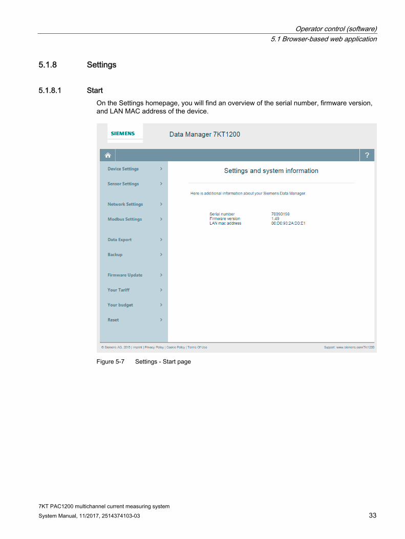
5.1.8.1 Start On the Settings homepage, you will find an overview of the serial number, firmware version, and LAN MAC address of the device.
Figure 5-7 Settings - Start page

Operator control (software) 5.1 Browser-based web application
7KT PAC1200 multichannel current measuring system 34 System Manual, 11/2017, 2514374103-03
5.1.8.2 Device In the menu item Device Settings, the following settings can be made:
● Language
● Location
● Date
● Time of day
● Transformer ratio
● Password
These settings appear on initial commissioning of the Data Manager.
Figure 5-8 Device settings
5.1.8.3 Sensors Under Sensor settings you will find two views:
● Sensor settings
● Current values

Operator control (software) 5.1 Browser-based web application
7KT PAC1200 multichannel current measuring system System Manual, 11/2017, 2514374103-03 35
Sensor settings In the Sensor settings, you can search for sensor bars connected to the Data Manager by clicking the button "Rescan sensor bus".
As soon as the sensor bars are detected, they appear in the left-hand column.
The number of sensor bars is detected automatically. The sensors can be assigned individual names, and they must be assigned to individual phases. In special applications, the power factor can also be defined manually. If a sensor is not connected, there is also no need for any phase assignment.
An eye symbol on the far right shows which sensors are to be compared with each other statistically. This can be adapted individually. Up to eight sensors can be compared with each other, regardless of whether they are located on the same sensor bar or not. The sensors that are to be compared with each other need only be connected to the same Data Manager.
Operator control (software) 5.1 Browser-based web application
7KT PAC1200 multichannel current measuring system 36 System Manual, 11/2017, 2514374103-03
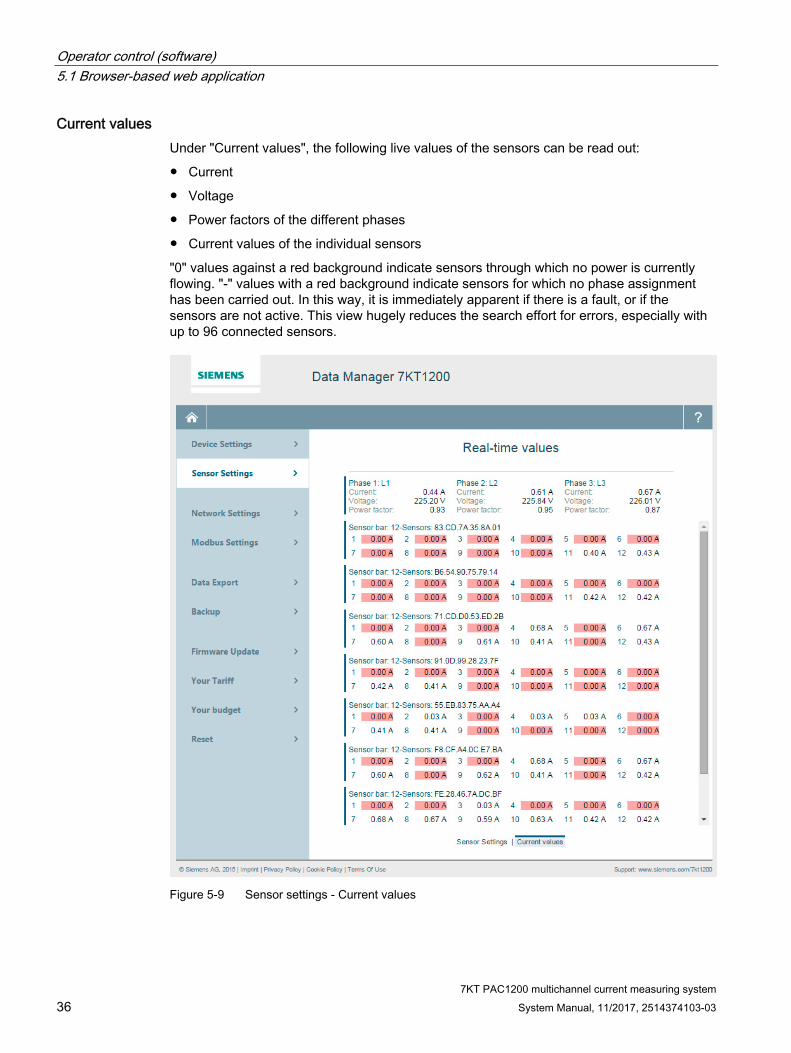
Current values Under "Current values", the following live values of the sensors can be read out:
● Current
● Voltage
● Power factors of the different phases
● Current values of the individual sensors
"0" values against a red background indicate sensors through which no power is currently flowing. "-" values with a red background indicate sensors for which no phase assignment has been carried out. In this way, it is immediately apparent if there is a fault, or if the sensors are not active. This view hugely reduces the search effort for errors, especially with up to 96 connected sensors.
Figure 5-9 Sensor settings - Current values
Operator control (software) 5.1 Browser-based web application
7KT PAC1200 multichannel current measuring system System Manual, 11/2017, 2514374103-03 37
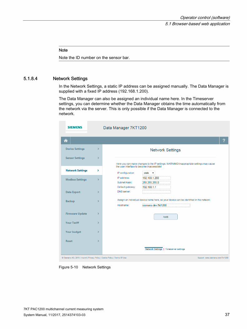
Note
Note the ID number on the sensor bar.
5.1.8.4 Network Settings In the Network Settings, a static IP address can be assigned manually. The Data Manager is supplied with a fixed IP address (192.168.1.200).
The Data Manager can also be assigned an individual name here. In the Timeserver settings, you can determine whether the Data Manager obtains the time automatically from the network via the server. This is only possible if the Data Manager is connected to the network.
Figure 5-10 Network Settings

Operator control (software) 5.1 Browser-based web application
7KT PAC1200 multichannel current measuring system 38 System Manual, 11/2017, 2514374103-03
5.1.8.5 Data export Data transfer is configured via the Modbus settings. All measured values are transferred through this connection. As a bidirectional counter, the Data Manager measures active power [W], reactive power [var], apparent power [VA] and power factor per phase and in total, current [A] and voltage [V] per phase, and the network frequency [Hz].
The Data Manager provides a Modbus TCP server that uses the standard port 502 for incoming connection enquiries. This port and the IP address must be configured to establish a connection with the Data Manager.
Data export In the case of data export, a CSV file is exported. This contains the instantaneous overall consumption and the consumption of the individual sensors in € and kWh. To enable recording of the values of the individual sensors in the CSV file, data transmission via Modbus must be activated, and the individual phases must be assigned to the sensors. If these settings are not made, only the overall consumption is recorded.
The following settings can be made in the "Data Export” dialog:
● Sensors that must appear in the CSV file
● Resolution: 15 min., 1 hour, 1 day and 1 week Values for 15 min for max. 1 year Values 1 day for max. 10 years
● Time frame: If the period extends back more than one week, representation in increments of 15 minutes is no longer possible.

Operator control (software) 5.1 Browser-based web application
7KT PAC1200 multichannel current measuring system System Manual, 11/2017, 2514374103-03 39
Figure 5-11 Data export

Operator control (software) 5.1 Browser-based web application
7KT PAC1200 multichannel current measuring system 40 System Manual, 11/2017, 2514374103-03
Data export with counter statuses and instantaneous values As well as the data export described above, there is the option of exporting a CSV file with the meter statuses and instantaneous values.
This export variant is automated, in other words, data are exported, saved and sent by email, or stored on an FTP server over a specified period.
Here too, there is the option of activating data logging, which results in a CSV file being saved to the hard disk at a specific resolution. In this file, you will find total power, overall consumption, current, voltage, and power factor. These data are also included, divided according to the different phases and the individual sensors.
Figure 5-12 Data export with counter statuses and instantaneous values
The settings made and the meter statuses can be downloaded and saved at any time by means of data backup. This data backup can be restored.

Operator control (software) 5.1 Browser-based web application
7KT PAC1200 multichannel current measuring system System Manual, 11/2017, 2514374103-03 41
5.1.8.6 Firmware update Current updates can be installed on the Data Manager in the “Firmware Update” menu.
Before this can take place, a data backup must be carried out.
The firmware update can then be installed. The Data Manager restarts automatically following installation, and changes to the Start page. Firmware updates can be found in Industry Online Support (https://support.industry.siemens.com/cs/ww/en/ps/21681).
See also Firmware Update (https://support.industry.siemens.com/cs/ww/en/ps/21681)
5.1.8.7 Tariff settings
Edit tariff The following values can be processed under Tariff:
The following currencies can be selected: EUR, US dollar, CHF
● Currency in which the tariff is to be presented
● Tariff name
● Monthly basic charge including value added tax
● Current rate

Operator control (software) 5.1 Browser-based web application
7KT PAC1200 multichannel current measuring system 42 System Manual, 11/2017, 2514374103-03
Figure 5-13 Tariff settings
Adjust tariff Under "Adjust tariff", the tariff can be changed at a particular time.
Operator control (software) 5.1 Browser-based web application
7KT PAC1200 multichannel current measuring system System Manual, 11/2017, 2514374103-03 43
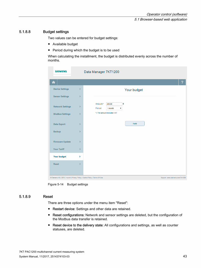
5.1.8.8 Budget settings Two values can be entered for budget settings:
● Available budget
● Period during which the budget is to be used
When calculating the installment, the budget is distributed evenly across the number of months.
Figure 5-14 Budget settings
5.1.8.9 Reset There are three options under the menu item "Reset":
● Restart device: Settings and other data are retained.
● Reset configurations: Network and sensor settings are deleted, but the configuration of the Modbus data transfer is retained.
● Reset device to the delivery state: All configurations and settings, as well as counter statuses, are deleted.

Operator control (software) 5.2 Application for mobile devices
7KT PAC1200 multichannel current measuring system 44 System Manual, 11/2017, 2514374103-03
5.2 Application for mobile devices
5.2.1 Getting started As well as the browser-based web application, there is also an application for mobile devices. The application can only be used to monitor and not to configure. The web application must be used for configuration.
Configurations set in the browser-based web application synchronize with the mobile application.
To use the application for mobile devices, it must first be installed on the desired devices. The procedure depends on the device used.
Android device Download the application from Google Play Store (https://play.google.com/store/apps/details?id=de.siemens.homebox&utm_source=global_co&utm_medium=prtnr&utm_content=Mar2515&utm_campaign=PartBadge&pcampaignid=MKT-Other-global-all-co-prtnr-py-PartBadge-Mar2515-1).
iOS device Download the application from Apple iTunes (https://geo.itunes.apple.com/us/app/7kt-pac1200/id1091508286?mt=8).
Start of the application If the application is started following successful installation, an automatic search is made for available multi-channel current measuring systems.
The found systems are listed on a Start screen.

Operator control (software) 5.2 Application for mobile devices
7KT PAC1200 multichannel current measuring system System Manual, 11/2017, 2514374103-03 45
The system to be monitored can now be selected from this list.
See also Android link (https://play.google.com/store/apps/details?id=de.siemens.homebox&utm_source=global_co&utm_medium=prtnr&utm_content=Mar2515&utm_campaign=PartBadge&pcampaignid=MKT-Other-global-all-co-prtnr-py-PartBadge-Mar2515-1)
iOS link (https://geo.itunes.apple.com/us/app/7kt-pac1200/id1091508286?mt=8)
Android screen (https://play.google.com/intl/en_us/badges/images/generic/de-play-badge.png)
iOS screen (http://linkmaker.itunes.apple.com/images/badges/en-us/badge_appstore-lrg.svg)

Operator control (software) 5.2 Application for mobile devices
7KT PAC1200 multichannel current measuring system 46 System Manual, 11/2017, 2514374103-03
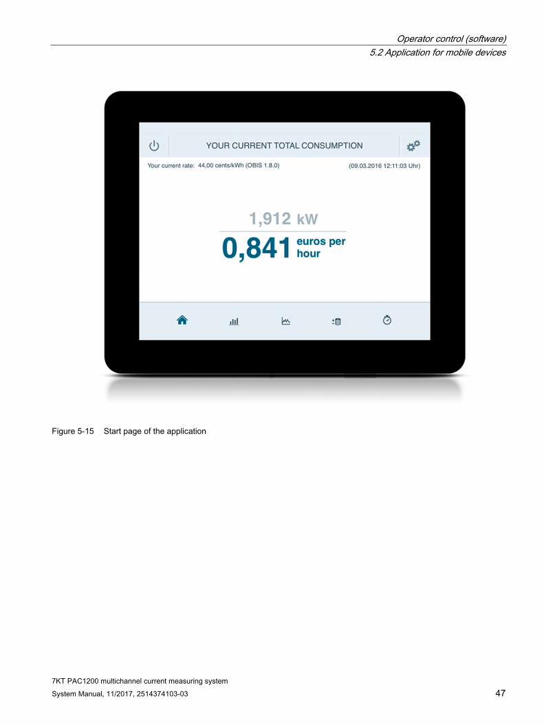
5.2.2 Home After a multichannel current measuring system has been selected, the Home page showing the current energy consumption appears.
Further information on available on the Home page:
● Date and time
● Navigation to:
– Statistics
– Current values
– Installment
– Energy stopwatch
● Closing of the selected multichannel current measuring system: Display returns to the selection of the detected systems.
● "Swipe" to the left / right to change between hourly, daily, weekly, monthly and annual consumption.
Operator control (software) 5.2 Application for mobile devices
7KT PAC1200 multichannel current measuring system System Manual, 11/2017, 2514374103-03 47
Figure 5-15 Start page of the application

Operator control (software) 5.2 Application for mobile devices
7KT PAC1200 multichannel current measuring system 48 System Manual, 11/2017, 2514374103-03
5.2.3 Statistics The Statistics view offers the following evaluations:
● Overall consumption
● Individual system consumption
● Individual consumption
● Consumption of the individual sensors
Consumption (top right) can be shown in:
● €
● kWh
Possible display intervals:
● Hour
● Day
● Week
● Month
● Year

Operator control (software) 5.2 Application for mobile devices
7KT PAC1200 multichannel current measuring system System Manual, 11/2017, 2514374103-03 49
Overall consumption Overall consumption is visualized using a bar chart.

Operator control (software) 5.2 Application for mobile devices
7KT PAC1200 multichannel current measuring system 50 System Manual, 11/2017, 2514374103-03
Individual system consumption Individual system consumption is displayed in the form of a pie chart. The sensors selected in the Sensor settings are displayed here in a direct comparison.
Individual consumption In the case of individual consumption, all selected sensors are represented underneath each other in a horizontal bar chart.
In this way, the individual sensors can be compared at a glance. This in turn means that differences in consumption of the individual sensors can be quickly detected.
All sensors connected to the Data Manager, as well as in the web interface, can, of course, also be looked at individually.
This is represented in the form of a bar chart.

Operator control (software) 5.2 Application for mobile devices
7KT PAC1200 multichannel current measuring system System Manual, 11/2017, 2514374103-03 51
5.2.4 Current values The current values are represented in real time, exactly as in the browser-based web application.
It is possible to stop the recording here. The latest current (power) values are also shown in the current values.
Figure 5-16 Current values - Overall consumption

Operator control (software) 5.2 Application for mobile devices
7KT PAC1200 multichannel current measuring system 52 System Manual, 11/2017, 2514374103-03
Figure 5-17 Current values - Current values
Another method of accessing the Data Manager via the application is to use the energy stopwatch. This can be started and stopped again.

7KT PAC1200 multichannel current measuring system System Manual, 11/2017, 2514374103-03 53
Service and maintenance 66.1 Error messages
The Status LED does not light up Problem: The Data Manager is not supplied with power.
Solution: Ensure that at least the line conductor L1 and the neutral conductor N are connected to the Data Manager.
The Status LED lights up or flashes red. Problem: There is a fault.
Solution: Restart Data Manager.
Solution: Contact Service.
The network LED does not light up, or the Data Manager is not found in the network. Problem: The network cable is not correctly connected to the network connection.
Solution: Ensure that the network cable is correctly connected to the network connection.
Problem: The Data Manager is not located in the same local network.
Solution: Connect the Data Manager with the same router / switch, or change the IP address in the PC.
The Energy Manager supplies unrealistic measured values. Problem: The Data Manager has been installed incorrectly.
Solution: Check connection of L1 to L3 again.
6.2 Disposal The system must be disposed of in accordance with the locally applicable regulations for the disposal of electronic waste.


7KT PAC1200 multichannel current measuring system System Manual, 11/2017, 2514374103-03 55
Technical data 7
Interfaces (standard) ● LAN (10 / 100 Mbits)
● RS485 for data transfer by means of Modbus RTU
Voltage and current inputs Rated voltage 110/230 V Operating voltage 230 V ± 10 % Frequency 50/60 Hz ± 5 %
Intrinsic consumption Voltage circuit < 0.01 VA per phase Current circuit < 2 VA per phase Overall device < 5 W Rated current 5 A Current limit 63 A Starting current < 25 mA
Mounting Conductor cross-section 10 ... 25 mm2 (mechanically from
1.5 ... 25 mm2) Torque for screw terminals 2.0 Nm
Technical data
7KT PAC1200 multichannel current measuring system 56 System Manual, 11/2017, 2514374103-03
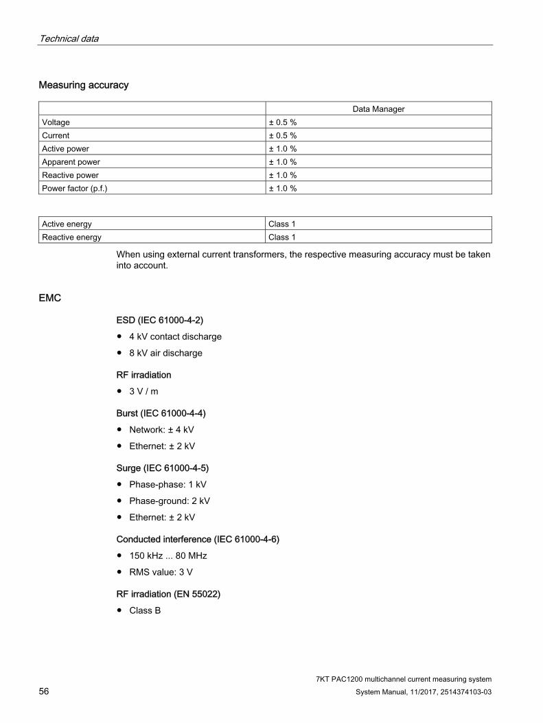
Measuring accuracy Data Manager Voltage ± 0.5 % Current ± 0.5 % Active power ± 1.0 % Apparent power ± 1.0 % Reactive power ± 1.0 % Power factor (p.f.) ± 1.0 %
Active energy Class 1 Reactive energy Class 1
When using external current transformers, the respective measuring accuracy must be taken into account.
EMC
ESD (IEC 61000-4-2)
● 4 kV contact discharge
● 8 kV air discharge
RF irradiation
● 3 V / m
Burst (IEC 61000-4-4)
● Network: ± 4 kV
● Ethernet: ± 2 kV
Surge (IEC 61000-4-5)
● Phase-phase: 1 kV
● Phase-ground: 2 kV
● Ethernet: ± 2 kV
Conducted interference (IEC 61000-4-6)
● 150 kHz ... 80 MHz
● RMS value: 3 V
RF irradiation (EN 55022)
● Class B

Technical data
7KT PAC1200 multichannel current measuring system System Manual, 11/2017, 2514374103-03 57
Operating conditions
● Ambient temperature: - 25°C ... + 45°C
● Storage temperature: - 25°C ... + 70°C
● Relative humidity:
– Up to 75 % annual average
– Up to 95 % on up to 30 days / year
Mechanical data
● Material enclosure: Glass-fiber reinforced polyamide
● Glow-wire test: According to IEC 695-2-1
● Protection class / type: II / IP20
● Weight / size: 0.3 kg / 88x70x65 mm
RS485 interface
Protocol Modbus Type RS485 half-duplex Data transmission rate 19200 or 115200 kbits Connectors 4-pin male connector 2.54 mm, enclosure
Proprietary RS 485 driver Slew-rate limited, CS-Sensor MAX13412 Electrical isolation No Power supplies for sensors Yes (280 mA) Voltage (min, max, typ.) min. 8 V, max. 10 V, typ. 9 V Short-circuit protection of power supply Yes

Technical data 7.1 Dimension drawings
7KT PAC1200 multichannel current measuring system 58 System Manual, 11/2017, 2514374103-03
Table 7- 1 Connector assignments
Pin direct Pin indirect Description 1 4 Supply voltage 9 V 2 3 RS485-B 3 2 RS485-A 4 1 Ground
7.1 Dimension drawings
7.1.1 Dimensions of the Data Manager
View from the right and from the front

Technical data 7.1 Dimension drawings
7KT PAC1200 multichannel current measuring system System Manual, 11/2017, 2514374103-03 59
View from above and from below
7.1.2 Dimensions of the sensor bar
Sensor bar with three sensor slots

Technical data 7.1 Dimension drawings
7KT PAC1200 multichannel current measuring system 60 System Manual, 11/2017, 2514374103-03
Sensor bar with six sensor slots

Technical data 7.1 Dimension drawings
7KT PAC1200 multichannel current measuring system System Manual, 11/2017, 2514374103-03 61
Sensor bar with nine sensor slots

Technical data 7.1 Dimension drawings
7KT PAC1200 multichannel current measuring system 62 System Manual, 11/2017, 2514374103-03
Sensor bar with twelve sensor slots

Technical data 7.1 Dimension drawings
7KT PAC1200 multichannel current measuring system System Manual, 11/2017, 2514374103-03 63
7.1.3 Dimensions of the sensors on the sensor bar


7KT PAC1200 multichannel current measuring system System Manual, 11/2017, 2514374103-03 65
Appendix AA.1 FAQs
What is the measuring accuracy of the overall system? Data Manager 1 %, overall system 2 %
At which intervals are the sensor values transferred to Siemens Data Manager? < 1 second
In which languages can the system be configured? In German and English.
Is the actual current communicated by the sensors or only a ratio? The current is measured (in amperes).
Is mixed operation of 40 A and 63 A sensors possible in the case of the sensor bar? It is possible.

Appendix A.2 Modbus register list
7KT PAC1200 multichannel current measuring system 66 System Manual, 11/2017, 2514374103-03
A.2 Modbus register list
Register overview
Start address (decimal)
End address (decimal)
Start address (hexadecimal)
End address (hexadecimal)
Size Description
0 145 0x0000 0x0091 146 See 4.1 Internal, immediate registers
512 791 0x0200 0x0317 280 See 4.2 Internal energy registers (meters)
8192 8243 0x2000 0x02033 52 See 4-3 PnP registers
40000 40177 0x9C40 0x9CF1 1788 See 4.4 SunSpec registers
61440 65183 0xF000 0xFEFF 3840 See 4.5 Sensor registers
A.3 Internal registers
Internal, immediate registers
Start address (deci-mal)
End address (deci-mal)
Start address (hexa-decimal)
End address (hexa-decimal)
Size R/W Func-tion codes
Type Units OBIS code Description
0 1 0x0000 0x0001 2 RO 0x03 Unit 32 0.1 W 1-0:1.4.0*255 Active power +
2 3 0x0002 0x0003 2 RO 0x03 Unit 32 0.1 W 1-0:2.4.0*255 Active power -4 5 0x0004 0x0005 2 RO 0x03 Unit 32 0.1 var 1-0:3.4.0*255 Reactive
power + 6 7 0x0006 0x0007 2 RO 0x03 Unit 32 0.1 var 1-0:4.4.0*255 Reactive
power - 8 9 0x0008 0x0009 2 RO 0x03 — — — (reserved) 10 11 0x000A 0x000B 2 RO 0x03 — — — (reserved) 12 13 0x000C 0x000D 2 RO 0x03 — — — (reserved) 14 15 0x000E 0x000F 2 RO 0x03 — — — (reserved) 16 17 0x0010 0x0011 2 RO 0x03 Unit 32 0.1 VA 1-0:9.4.0*255 Apparent
power +

Appendix A.3 Internal registers
7KT PAC1200 multichannel current measuring system System Manual, 11/2017, 2514374103-03 67
18 19 0x0012 0x0013 2 RO 0x03 Unit 32 0.1 VA 1-0:10.4.0*255 Apparent power -
20 21 0x0014 0x0015 2 RO 0x03 — — — (reserved) 22 23 0x0016 0x0017 2 RO 0x03 — — — (reserved) 24 25 0x0018 0x0019 2 RO 0x03 Unit 32 0.001 (no
unit) 1-0:13.4.0*255 Power factor
26 27 0x001A 0x001B 2 RO 0x03 Unit 32 0.001 Hz 1-0:14.4.0*255 Line frequen-cy
28 29 0x001C 0x001D 2 RO 0x03 — — — (reserved) 30 31 0x001E 0x001F 2 RO 0x03 — — — (reserved) 32 33 0x0020 0x0021 2 RO 0x03 — — — (reserved) 34 35 0x0022 0x0023 2 RO 0x03 — — — (reserved) 36 37 0x0024 0x0025 2 RO 0x03 — — — (reserved) 38 39 0x0026 0x0027 2 RO 0x03 — — — (reserved) 40 41 0x0028 0x0029 2 RO 0x03 Unit 32 0.1 W 1-0:21.4.0*255 Active power
+ (L1) 42 43 0x002A 0x002B 2 RO 0x03 Unit 32 0.1 W 1-0:22.4.0*255 Active power -
(L1) 44 45 0x002C 0x002D 2 RO 0x03 Unit 32 0.1 var 1-0:23.4.0*255 Reactive
power + (L1) 46 47 0x002E 0x002F 2 RO 0x03 Unit 32 0.1 var 1-0:24.4.0*255 Reactive
power - (L1) 48 49 0x0030 0x0031 2 RO 0x03 — — — (reserved) 50 51 0x0032 0x0033 2 RO 0x03 — — — (reserved) 52 53 0x0034 0x0035 2 RO 0x03 — — — (reserved) 54 55 0x0036 0x0037 2 RO 0x03 — — — (reserved) 56 57 0x0038 0x0039 2 RO 0x03 Unit 32 0.1 VA 1-0:29.4.0*255 Active power
+ (L1) 58 59 0x003A 0x003B 2 RO 0x03 Unit 32 0.1 VA 1-0:30.4.0*255 Active power -
(L1) 60 61 0x003C 0x003D 2 RO 0x03 Unit 32 0.001 A 1-0:31.4.0*255 Current (L1) 62 63 0x003E 0x003F 2 RO 0x03 Unit 32 0.001 V 1-0:32.4.0*255 Current po-
tential (L1) 64 65 0x0040 0x0041 2 RO 0x03 Unit 32 0.001 (no
unit) 1-0:33.4.0*255 Power factor
(L1) 66 67 0x0042 0x0043 2 RO 0x03 — — — (reserved) 68 69 0x0044 0x0045 2 RO 0x03 — — — (reserved) 70 71 0x0046 0x0047 2 RO 0x03 — — — (reserved) 72 73 0x0048 0x0049 2 RO 0x03 — — — (reserved) 74 75 0x004A 0x004B 2 RO 0x03 — — — (reserved) 76 77 0x004C 0x004D 2 RO 0x03 — — — (reserved) 78 79 0x004E 0x004F 2 RO 0x03 — — — (reserved) 80 81 0x0050 0x0051 2 RO 0x03 Unit 32 0.1 W 1-0:41.4.0*255 Active power
+ (L2) 82 83 0x0052 0x0053 2 RO 0x03 Unit 32 0.1 W 1-0:42.4.0*255 Active power -
(L2)

Appendix A.3 Internal registers
7KT PAC1200 multichannel current measuring system 68 System Manual, 11/2017, 2514374103-03
84 85 0x0054 0x0055 2 RO 0x03 Unit 32 0.1 var 1-0:43.4.0*255 Reactive power + (L2)
86 87 0x0056 0x0057 2 RO 0x03 Unit 32 0.1 var 1-0:44.4.0*255 Reactive power - (L2)
88 89 0x0058 0x0059 2 RO 0x03 — — — (reserved) 90 91 0x005A 0x005B 2 RO 0x03 — — — (reserved) 92 93 0x005C 0x005D 2 RO 0x03 — — — (reserved) 94 95 0x005E 0x005F 2 RO 0x03 — — — (reserved) 96 97 0x0060 0x0061 2 RO 0x03 Unit 32 0.1 VA 1-0:49.4.0*255 Active power
+ (L2) 98 99 0x0062 0x0063 2 RO 0x03 Unit 32 0.1 VA 1-0:50.4.0*255 Active power -
(L2) 100 101 0x0064 0x0065 2 RO 0x03 Unit 32 0.001 A 1-0:51.4.0*255 Current (L2) 102 103 0x0066 0x0067 2 RO 0x03 Unit 32 0.001 V 1-0:52.4.0*255 Current po-
tential (L2) 104 105 0x0068 0x0069 2 RO 0x03 Unit 32 0.001 (no
unit) 1-0:53.4.0*255 Power factor
(L2) 106 107 0x006A 0x006B 2 RO 0x03 — — — (reserved) 108 109 0x006C 0x006D 2 RO 0x03 — — — (reserved) 110 111 0x006E 0x006F 2 RO 0x03 — — — (reserved) 112 113 0x0070 0x0071 2 RO 0x03 — — — (reserved) 114 115 0x0072 0x0073 2 RO 0x03 — — — (reserved) 116 117 0x0074 0x0075 2 RO 0x03 — — — (reserved) 118 119 0x0076 0x0077 2 RO 0x03 — — — (reserved) 120 121 0x0078 0x0079 2 RO 0x03 Unit 32 0.1 W 1-0:61.4.0*255 Active power
+ (L3) 122 123 0x007A 0x007B 2 RO 0x03 Unit 32 0.1 W 1-0:62.4.0*255 Active power -
(L3) 124 125 0x007C 0x007D 2 RO 0x03 Unit 32 0.1 var 1-0:63.4.0*255 Reactive
power + (L3) 126 127 0x007E 0x007F 2 RO 0x03 Unit 32 0.1 var 1-0:64.4.0*255 Reactive
power - (L3) 128 129 0x0080 0x0081 2 RO 0x03 — — — (reserved) 130 131 0x0082 0x0083 2 RO 0x03 — — — (reserved) 132 133 0x0084 0x0085 2 RO 0x03 — — — (reserved) 134 135 0x0086 0x0087 2 RO 0x03 — — — (reserved) 136 137 0x0088 0x0089 2 RO 0x03 Unit 32 0.1 VA 1-0:69.4.0*255 Active power
+ (L3) 138 139 0x008A 0x008B 2 RO 0x03 Unit 32 0.1 VA 1-0:70.4.0*255 Active power -
(L3) 140 141 0x008C 0x008D 2 RO 0x03 Unit 32 0.001 A 1-0:71.4.0*255 Current (L3) 142 143 0x008E 0x008F 2 RO 0x03 Unit 32 0.001 V 1-0:72.4.0*255 Current po-
tential (L3) 144 145 0x0090 0x0091 2 RO 0x03 Unit 32 0.001 (no
unit) 1-0:73.4.0*255 Power factor
(L3)

Appendix A.3 Internal registers
7KT PAC1200 multichannel current measuring system System Manual, 11/2017, 2514374103-03 69
Internal energy registers (meters)
Start address (deci-mal)
End address (deci-mal)
Start address (hexa-decimal)
End address (hexa-decimal)
Size R/W Func-tion codes
Type Units OBIS code Description
512 515 0x0200 0x0203 4 RO 0x03 Unit 64 0.1 Wh 1-0:1.8.0*255 Active power +
516 519 0x0204 0x0207 4 RO 0x03 Unit 64 0.1 Wh 1-0:2.8.0*255 Active power -520 523 0x0208 0x020B 4 RO 0x03 Unit 64 0.1 varh 1-0:3.8.0*255 Reactive
power + 524 527 0x020C 0x020F 4 RO 0x03 Unit 64 0.1 varh 1-0:4.8.0*255 Reactive
power - 528 531 0x0210 0x0213 4 RO 0x03 — — — (reserved) 532 535 0x0214 0x0217 4 RO 0x03 — — — (reserved) 536 539 0x0218 0x021B 4 RO 0x03 — — — (reserved) 540 543 0x021C 0x021F 4 RO 0x03 — — — (reserved) 544 547 0x0220 0x0223 4 RO 0x03 Unit 64 0.1 VAh 1-0:9.8.0*255 Apparent
power + 548 551 0x0224 0x0227 4 RO 0x03 Unit 64 0.1 VAh 1-0:10.8.0*255 Apparent
power - 552 555 0x0228 0x022B 4 RO 0x03 — — — (reserved) 556 559 0x022C 0x022F 4 RO 0x03 — — — (reserved) 560 563 0x0230 0x0233 4 RO 0x03 — — — (reserved) 564 567 0x0234 0x0237 4 RO 0x03 — — — (reserved) 568 571 0x0238 0x023B 4 RO 0x03 — — — (reserved) 572 575 0x023C 0x023F 4 RO 0x03 — — — (reserved) 576 579 0x0240 0x0243 4 RO 0x03 — — — (reserved) 580 583 0x0244 0x0247 4 RO 0x03 — — — (reserved) 584 587 0x0248 0x024B 4 RO 0x03 — — — (reserved) 588 591 0x024C 0x024F 4 RO 0x03 — — — (reserved) 592 595 0x0250 0x0253 4 RO 0x03 Unit 64 0.1 Wh 1-0:21.8.0*255 Active power
+ (L1) 596 599 0x0254 0x0257 4 RO 0x03 Unit 64 0.1 Wh 1-0:22.8.0*255 Active power -
(L1) 600 603 0x0258 0x025B 4 RO 0x03 Unit 64 0.1 varh 1-0:23.8.0*255 Reactive
power + (L1) 604 607 0x025C 0x025F 4 RO 0x03 Unit 64 0.1 varh 1-0:24.8.0*255 Reactive
power - (L1) 608 611 0x0260 0x0263 4 RO 0x03 — — — (reserved) 612 615 0x0264 0x0267 4 RO 0x03 — — — (reserved) 616 619 0x0268 0x026B 4 RO 0x03 — — — (reserved) 620 623 0x026C 0x026F 4 RO 0x03 — — — (reserved) 624 627 0x0270 0x0273 4 RO 0x03 Unit 64 0.1 VAh 1-0:29.8.0*255 Apparent
power + (L1)

Appendix A.3 Internal registers
7KT PAC1200 multichannel current measuring system 70 System Manual, 11/2017, 2514374103-03
628 631 0x0274 0x0277 4 RO 0x03 Unit 64 0.1 VAh 1-0:30.8.0*255 Apparent power - (L1)
632 635 0x0278 0x027B 4 RO 0x03 — — — (reserved) 636 639 0x027C 0x027F 4 RO 0x03 — — — (reserved) 640 643 0x0280 0x0283 4 RO 0x03 — — — (reserved) 644 647 0x0284 0x0287 4 RO 0x03 — — — (reserved) 648 651 0x0288 0x028B 4 RO 0x03 — — — (reserved) 652 655 0x028C 0x028F 4 RO 0x03 — — — (reserved) 656 659 0x0290 0x0293 4 RO 0x03 — — — (reserved) 660 663 0x0294 0x0297 4 RO 0x03 — — — (reserved) 664 667 0x0298 0x029B 4 RO 0x03 — — — (reserved) 668 671 0x029C 0x029F 4 RO 0x03 — — — (reserved) 672 675 0x02A0 0x02A3 4 RO 0x03 Unit 64 0.1 Wh 1-0:41.8.0*255 Active power
+ (L2) 676 679 0x02A4 0x02A7 4 RO 0x03 Unit 64 0.1 Wh 1-0:42.8.0*255 Active power -
(L2) 680 683 0x02A8 0x02AB 4 RO 0x03 Unit 64 0.1 varh 1-0:43.8.0*255 Reactive
power + (L2) 684 687 0x02AC 0x02AF 4 RO 0x03 Unit 64 0.1 varh 1-0:44.8.0*255 Reactive
power - (L2) 688 691 0x02B0 0x02B3 4 RO 0x03 — — — (reserved) 692 695 0x02B4 0x02B7 4 RO 0x03 — — — (reserved) 696 699 0x02B8 0x02BB 4 RO 0x03 — — — (reserved) 700 703 0x02BC 0x02BF 4 RO 0x03 — — — (reserved) 704 707 0x02C0 0x02C3 4 RO 0x03 Unit 64 0.1 VAh 1-0:49.8.0*255 Apparent
power + (L2) 708 711 0x02C4 0x02C7 4 RO 0x03 Unit 64 0.1 VAh 1-0:50.8.0*255 Apparent
power - (L2) 712 715 0x02C8 0x02CB 4 RO 0x03 — — — (reserved) 716 719 0x02CC 0x02CF 4 RO 0x03 — — — (reserved) 720 723 0x02D0 0x02D3 4 RO 0x03 — — — (reserved) 724 727 0x02D4 0x02D7 4 RO 0x03 — — — (reserved) 728 731 0x02D8 0x02DB 4 RO 0x03 — — — (reserved) 732 735 0x02DC 0x02DF 4 RO 0x03 — — — (reserved) 736 739 0x02E0 0x02E3 4 RO 0x03 — — — (reserved) 740 743 0x02E4 0x02E7 4 RO 0x03 — — — (reserved) 744 747 0x02E8 0x02EB 4 RO 0x03 — — — (reserved) 748 751 0x02EC 0x02EF 4 RO 0x03 — — — (reserved) 752 755 0x02F0 0x02F3 4 RO 0x03 Unit 64 0.1 Wh 1-0:61.8.0*255 Active power
+ (L3) 756 759 0x02F4 0x02F7 4 RO 0x03 Unit 64 0.1 Wh 1-0:62.8.0*255 Active power -
(L3) 760 763 0x02F8 0x02FB 4 RO 0x03 Unit 64 0.1 varh 1-0:63.8.0*255 Reactive
power + (L3) 764 767 0x02FC 0x02FF 4 RO 0x03 Unit 64 0.1 varh 1-0:64.8.0*255 Reactive
power - (L3)

Appendix A.3 Internal registers
7KT PAC1200 multichannel current measuring system System Manual, 11/2017, 2514374103-03 71
768 771 0x0300 0x0303 4 RO 0x03 — — — (reserved) 772 775 0x0304 0x0307 4 RO 0x03 — — — (reserved) 776 779 0x0308 0x030B 4 RO 0x03 — — — (reserved) 780 783 0x030C 0x030F 4 RO 0x03 — — — (reserved) 784 787 0x0310 0x0313 4 RO 0x03 Unit 64 0.1 VAh 1-0:69.8.0*255 Apparent
power + (L3) 788 791 0x0314 0x0317 4 RO 0x03 Unit 64 0.1 VAh 1-0:70.8.0*255 Apparent
power - (L3)
PnP registers
Start address (deci-mal)
End address (deci-mal)
Start address (hexa-decimal)
End address (hexa-decimal)
Size R/W Func-tion codes
Type Name Default val-ue/example
Description
8192 8192 0x2000 0x2000 1 RO 0x03 Unit 16 Manufac-turer's ID
0x5233 Fixed value to identify each device
8193 8193 0x2001 0x2001 1 RO 0x03 Unit 16 Product ID 0x4842 Indicates that the device is a Data Man-ager
8194 8194 0x2002 0x2002 1 RO 0x03 Unit 16 Product version
Example: 0x0200 (= 2.00)
(Hardware) revision of the Data Manager
8195 8195 0x2003 0x2003 1 RO 0x03 Unit 16 Firmware version
Example: 0x020D = 525 = 2.13
Firmware revision of the Data Manager
8196 8211 0x2004 0x2013 16 RO 0x03 Series (32)
Seller's name
Contains the manufactur-er's name as a series, padded with NUL bytes or blanks
8212 8227 0x2014 0x2023 16 RO 0x03 Series (32)
Product name
Contains the product name as a series, pad-ded with NUL bytes or blanks
8228 8243 0x2024 0x2033 16 RO 0x03 Series (32)
Serial number
Example: - 3.03809E+13
Contains the serial num-ber of the device
Appendix A.3 Internal registers
7KT PAC1200 multichannel current measuring system 72 System Manual, 11/2017, 2514374103-03
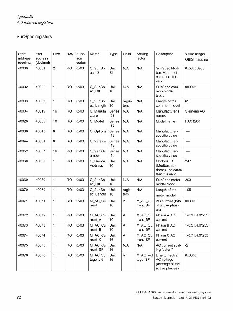
SunSpec registers
Start address (decimal)
End address (decimal)
Size R/W Func-tion codes
Name Type Units Scaling factor
Description Value range/ OBIS mapping
40000 40001 2 RO 0x03 C_SunSpec_ID
Unit 32
N/A N/A SunSpec Mod-bus Map. Indi-cates that it is valid.
0x53756e53
40002 40002 1 RO 0x03 C_SunSpec_DID
Unit 16
N/A N/A SunSpec com-mon model block
0x0001
40003 40003 1 RO 0x03 C_SunSpec_Length
Unit 16
regis-ters
N/A Length of the common model
65
40004 40019 16 RO 0x03 C_Manufacturer
Series (32)
N/A N/A Manufacturer's name:
Siemens AG
40020 40035 16 RO 0x03 C_Model Series (32)
N/A N/A Model name PAC1200
40036 40043 8 RO 0x03 C_Options Series (16)
N/A N/A Manufacturer-specific value
—
40044 40051 8 RO 0x03 C_Version Series (16)
N/A N/A Manufacturer-specific value
—
40052 40067 16 RO 0x03 C_SerialNumber
Series (16)
N/A N/A Manufacturer-specific value
—
40068 40068 1 RO 0x03 C_DeviceAddress
Unit 16
N/A N/A Modbus ID (Modbus ad-dress). Indicates that it is valid.
247
40069 40069 1 RO 0x03 C_SunSpec_DID
Unit 16
N/A N/A SunSpec meter model block
203
40070 40070 1 RO 0x03 C_SunSpec_Length
Unit 16
regis-ters
N/A Length of the meter model
105
40071 40071 1 RO 0x03 M_AC_Current
Unit 16
A M_AC_Current_SF
AC current (total of active phas-es)
0x8000
40072 40072 1 RO 0x03 M_AC_Current_A
Unit 16
A M_AC_Current_SF
Phase A AC current
1-0:31.4.0*255
40073 40073 1 RO 0x03 M_AC_Current_B
Unit 16
A M_AC_Current_SF
Phase B AC current
1-0:51.4.0*255
40074 40074 1 RO 0x03 M_AC_Current_C
Unit 16
A M_AC_Current_SF
Phase C AC current
1-0:71.4.0*255
40075 40075 1 RO 0x03 M_AC_Current_SF
Unit 16
N/A N/A AC current scal-ing factor**
-2
40076 40076 1 RO 0x03 M_AC_Voltage_LN
Unit 16
V M_AC_Voltage_SF
Line to neutral AC voltage (average of the active phases)
0x8000

Appendix A.3 Internal registers
7KT PAC1200 multichannel current measuring system System Manual, 11/2017, 2514374103-03 73
40077 40077 1 RO 0x03 M_AC_Voltage_AN
Unit 16
V M_AC_Voltage_SF
Phase A to neutral AC volt-age
1-0:32.4.0*255
40078 40078 1 RO 0x03 M_AC_Voltage_BN
Unit 16
V M_AC_Voltage_SF
Phase B to neutral AC volt-age
1-0:52.4.0*255
40079 40079 RO 0x03 M_AC_Voltage_CN
Unit 16
V M_AC_Voltage_SF
Phase C to neutral AC volt-age
1-0:72.4.0*255
40080 40080 1 RO 0x03 M_AC_Voltage_LL
Unit 16
V M_AC_Voltage_SF
Line to line AC voltage (average of the active phases)
0x8000
40081 40081 1 RO 0x03 M_AC_Voltage_AB
Unit 16
V M_AC_Voltage_SF
Phase A to phase B AC current potential
0x8000
40082 40082 1 RO 0x03 M_AC_Voltage_BC
Unit 16
V M_AC_Voltage_SF
Phase B to phase C AC current potential
0x8000
40083 40083 1 RO 0x03 M_AC_Voltage_CA
Unit 16
V M_AC_Voltage_SF
Phase C to phase A AC current potential
0x8000
40084 40084 1 RO 0x03 M_AC_Voltage_SF
Unit 16
N/A N/A AC current po-tential scaling factor**
-2
40085 40085 1 RO 0x03 M_AC_Freq
Unit 16
Hz M_AC_Freq_SF
AC frequency 1-0:14.4.0*255
40086 40086 1 RO 0x03 M_AC_Freq_SF
Unit 16
N/A N/A AC frequency scaling factor**
-2
40087 40087 1 RO 0x03 M_AC_Power
Unit 16
W M_AC_Power_SF
Total active power (total of active phases)
> 0 ≙ 1-0:1.4.0*255 < 0 ≙ 1-0:2.4.0*255
40088 40088 1 RO 0x03 M_AC_Power_A
Unit 16
W M_AC_Power_SF
Phase A AC total active pow-er
> 0 ≙ 1-0:21.4.0*255 < 0 ≙ 1-0:22.4.0*255
40089 40089 1 RO 0x03 M_AC_Power_B
Unit 16
W M_AC_Power_SF
Phase B AC total active pow-er
> 0 ≙ 1-0:41.4.0*255 < 0 ≙ 1-0:42.4.0*255
40090 40090 1 RO 0x03 M_AC_Power_C
Unit 16
W M_AC_Power_SF
Phase C AC total active pow-er
> 0 ≙ 1-0:61.4.0*255 < 0 ≙ 1-0:62.4.0*255
40091 40091 1 RO 0x03 M_AC_Power_SF
Unit 16
N/A N/A AC active power scaling factor**
1
Appendix A.3 Internal registers
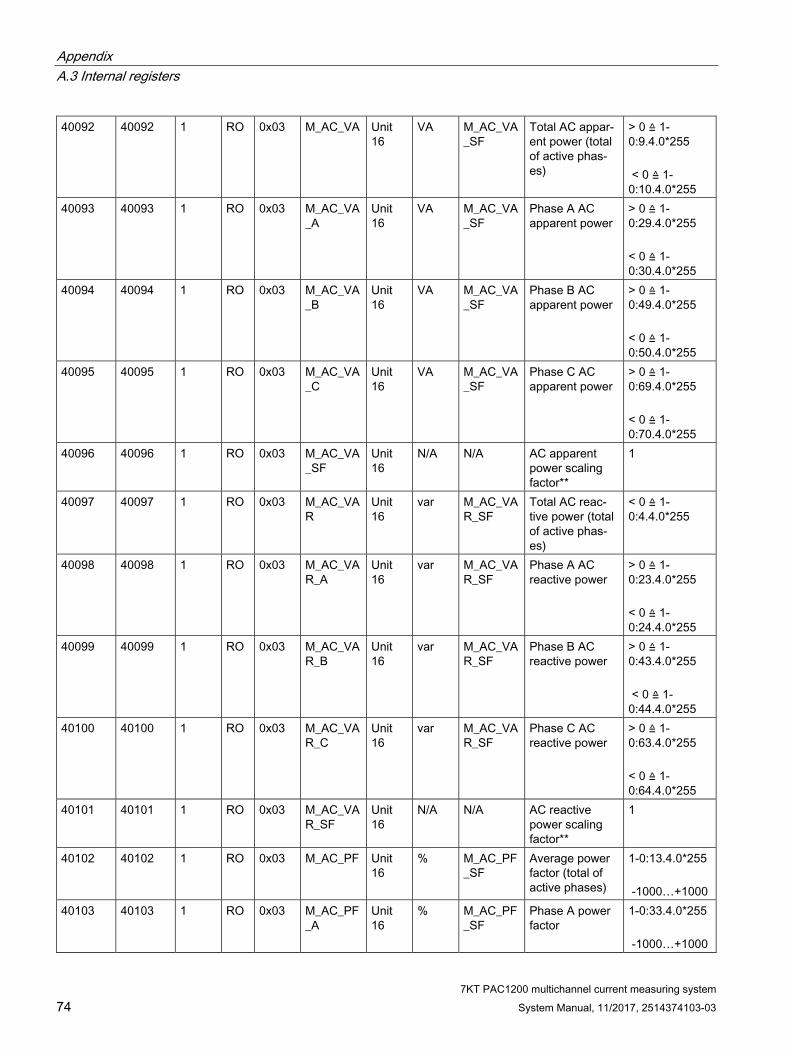
7KT PAC1200 multichannel current measuring system 74 System Manual, 11/2017, 2514374103-03
40092 40092 1 RO 0x03 M_AC_VA Unit 16
VA M_AC_VA_SF
Total AC appar-ent power (total of active phas-es)
> 0 ≙ 1-0:9.4.0*255 < 0 ≙ 1-0:10.4.0*255
40093 40093 1 RO 0x03 M_AC_VA_A
Unit 16
VA M_AC_VA_SF
Phase A AC apparent power
> 0 ≙ 1-0:29.4.0*255 < 0 ≙ 1-0:30.4.0*255
40094 40094 1 RO 0x03 M_AC_VA_B
Unit 16
VA M_AC_VA_SF
Phase B AC apparent power
> 0 ≙ 1-0:49.4.0*255 < 0 ≙ 1-0:50.4.0*255
40095 40095 1 RO 0x03 M_AC_VA_C
Unit 16
VA M_AC_VA_SF
Phase C AC apparent power
> 0 ≙ 1-0:69.4.0*255 < 0 ≙ 1-0:70.4.0*255
40096 40096 1 RO 0x03 M_AC_VA_SF
Unit 16
N/A N/A AC apparent power scaling factor**
1
40097 40097 1 RO 0x03 M_AC_VAR
Unit 16
var M_AC_VAR_SF
Total AC reac-tive power (total of active phas-es)
< 0 ≙ 1-0:4.4.0*255
40098 40098 1 RO 0x03 M_AC_VAR_A
Unit 16
var M_AC_VAR_SF
Phase A AC reactive power
> 0 ≙ 1-0:23.4.0*255 < 0 ≙ 1-0:24.4.0*255
40099 40099 1 RO 0x03 M_AC_VAR_B
Unit 16
var M_AC_VAR_SF
Phase B AC reactive power
> 0 ≙ 1-0:43.4.0*255 < 0 ≙ 1-0:44.4.0*255
40100 40100 1 RO 0x03 M_AC_VAR_C
Unit 16
var M_AC_VAR_SF
Phase C AC reactive power
> 0 ≙ 1-0:63.4.0*255 < 0 ≙ 1-0:64.4.0*255
40101 40101 1 RO 0x03 M_AC_VAR_SF
Unit 16
N/A N/A AC reactive power scaling factor**
1
40102 40102 1 RO 0x03 M_AC_PF Unit 16
% M_AC_PF_SF
Average power factor (total of active phases)
1-0:13.4.0*255 -1000…+1000
40103 40103 1 RO 0x03 M_AC_PF_A
Unit 16
% M_AC_PF_SF
Phase A power factor
1-0:33.4.0*255 -1000…+1000

Appendix A.3 Internal registers
7KT PAC1200 multichannel current measuring system System Manual, 11/2017, 2514374103-03 75
40104 40104 1 RO 0x03 M_AC_PF_B
Unit 16
% M_AC_PF_SF
Phase B power factor
1-0:53.4.0*255 -1000…+1000
40105 40105 1 RO 0x03 M_AC_PF_C
Unit 16
% M_AC_PF_SF
Phase C power factor
1-0:73.4.0*255 -1000…+1000
40106 40106 1 RO 0x03 M_AC_PF_SF
Unit 16
N/A N/A AC power factor scaling factor**
-3
40107 40108 2 RO 0x03 M_Exported
Unit 32
Wh M_Energy_W_SF
Total, exported real energy
1-0:2.8.0*255
40109 40110 2 RO 0x03 M_Exported_A
Unit 32
Wh M_Energy_W_SF
Phase A export-ed, real energy
1-0:22.8.0*255
40111 40112 2 RO 0x03 M_Exported_B
Unit 32
Wh M_Energy_W_SF
Phase B export-ed, real energy
1-0:42.8.0*255
40113 40114 2 RO 0x03 M_Exported_C
Unit 32
Wh M_Energy_W_SF
Phase C export-ed, real energy
1-0:62.8.0*255
40115 40116 2 RO 0x03 M_Imported
Unit 32
Wh M_Energy_W_SF
Total, imported real energy
1-0:1.8.0*255
40117 40118 2 RO 0x03 M_Imported_A
Unit 32
Wh M_Energy_W_SF
Phase A import-ed, real energy
1-0:21.8.0*255
40119 40120 2 RO 0x03 M_Imported_B
Unit 32
Wh M_Energy_W_SF
Phase B import-ed, real energy
1-0:41.8.0*255
40121 40122 2 RO 0x03 M_Imported_C
Unit 32
Wh M_Energy_W_SF
Phase C import-ed, real energy
1-0:61.8.0*255
40123 40123 1 RO 0x03 M_Energy_W_SF
Unit 16
N/A N/A Real energy scaling factor**
0
40124 40125 2 RO 0x03 M_Exported_VA
Unit 32
VAh M_Energy_VA_SF
Total exported apparent energy
1-0:10.8.0*255
40126 40127 2 RO 0x03 M_Exported_VA_A
Unit 32
VAh M_Energy_VA_SF
Phase A export-ed apparent energy
1-0:30.8.0*255
40128 40129 2 RO 0x03 M_Exported_VA_B
Unit 32
VAh M_Energy_VA_SF
Phase B export-ed apparent energy
1-0:50.8.0*255
40130 40131 2 RO 0x03 M_Exported_VA_C
Unit 32
VAh M_Energy_VA_SF
Phase C export-ed apparent energy
1-0:70.8.0*255
40132 40133 2 RO 0x03 M_Imported_VA
Unit 32
VAh M_Energy_VA_SF
Total, imported apparent energy
1-0:9.8.0*255
40134 40135 2 RO 0x03 M_Imported_VA_A
Unit 32
VAh M_Energy_VA_SF
Phase A import-ed apparent energy
1-0:29.8.0*255
40136 40137 2 RO 0x03 M_Imported_VA_B
Unit 32
VAh M_Energy_VA_SF
Phase B import-ed apparent energy
1-0:49.8.0*255
40138 40139 2 RO 0x03 M_Imported_VA_C
Unit 32
VAh M_Energy_VA_SF
Phase C import-ed apparent energy
1-0:69.8.0*255

Appendix A.3 Internal registers
7KT PAC1200 multichannel current measuring system 76 System Manual, 11/2017, 2514374103-03
40140 40140 1 RO 0x03 M_Energy_VA_SF
Unit 16
N/A N/A Apparent energy scaling factor**
0
40141 40142 2 RO 0x03 M_Import_VARh_Q1
Unit 32
VARh M_Energy_VAR_SF
Quadrant 1: total, imported reactive energy
0x80000000
40143 40144 2 RO 0x03 M_Import_VARh_Q1A
Unit 32
VARh M_Energy_VAR_SF
Phase A - quad-rant 1: imported reactive energy
0x80000000
40145 40146 2 RO 0x03 M_Import_VARh_Q1B
Unit 32
VARh M_Energy_VAR_SF
Phase B - quad-rant 1: imported reactive energy
0x80000000
40147 40148 2 RO 0x03 M_Import_VARh_Q1C
Unit 32
VARh M_Energy_VAR_SF
Phase C - quad-rant 1: imported reactive energy
0x80000000
40149 40150 2 RO 0x03 M_Import_VARh_Q2
Unit 32
VARh M_Energy_VAR_SF
Quadrant 2: total, imported reactive energy
0x80000000
40151 40152 2 RO 0x03 M_Import_VARh_Q2A
Unit 32
VARh M_Energy_VAR_SF
Phase A - quad-rant 2: imported reactive energy
0x80000000
40153 40154 2 RO 0x03 M_Import_VARh_Q2B
Unit 32
VARh M_Energy_VAR_SF
Phase B - quad-rant 2: imported reactive energy
0x80000000
40155 40156 2 RO 0x03 M_Import_VARh_Q2C
Unit 32
VARh M_Energy_VAR_SF
Phase C - quad-rant 2: imported reactive energy
0x80000000
40157 40158 2 RO 0x03 M_Export_VARh_Q3
Unit 32
VARh M_Energy_VAR_SF
Quadrant 3: total, imported reactive energy
0x80000000
40159 40160 2 RO 0x03 M_Export_VARh_Q3A
Unit 32
VARh M_Energy_VAR_SF
Phase A - quad-rant 3: imported reactive energy
0x80000000
40161 40162 2 RO 0x03 M_Export_VARh_Q3B
Unit 32
VARh M_Energy_VAR_SF
Phase B - quad-rant 3: imported reactive energy
0x80000000
40163 40164 2 RO 0x03 M_Export_VARh_Q3C
Unit 32
VARh M_Energy_VAR_SF
Phase C - quad-rant 3: imported reactive energy
0x80000000
40165 40166 2 RO 0x03 M_Export_VARh_Q4
Unit 32
VARh M_Energy_VAR_SF
Quadrant 4: total, imported reactive energy
0x80000000
40167 40168 2 RO 0x03 M_Export_VARh_Q4A
Unit 32
VARh M_Energy_VAR_SF
Phase A - quad-rant 4: imported reactive energy
0x80000000
40169 40170 2 RO 0x03 M_Export_VARh_Q4B
Unit 32
VARh M_Energy_VAR_SF
Phase B - quad-rant 4: imported reactive energy
0x80000000
40171 40172 2 RO 0x03 M_Export_VARh_Q4C
Unit 32
VARh M_Energy_VAR_SF
Phase C - quad-rant 4: imported reactive energy
0x80000000

Appendix A.4 Sensor registers
7KT PAC1200 multichannel current measuring system System Manual, 11/2017, 2514374103-03 77
40173 40173 1 RO 0x03 M_Energy_VAR_SF
Unit 16
N/A N/A Reactive energy scaling factor**
0
40174 40175 2 RO 0x03 M_Events Unit 32
N/A N/A Event flags - indicates that it is valid
0
40176 40176 1 RO 0x03 C_SunSpec_DID
Unit 16
N/A N/A SunSpec end model block
0xffff
40177 40177 1 RO 0x03 C_SunSpec_Length
Unit 16
regis-ters
N/A Length of end model
0
A.4 Sensor registers
Overview
Start address (decimal)
End address (decimal)
Start address (hexadecimal)
End address (hexadecimal)
Size Description
61440 61479 0xF000 0xF027 40 Sensor 1 61480 61519 0xF028 0xF04F 40 Sensor 2 … … … … … … 65240 65279 0xFED8 0xFEFF 40 Sensor 96

Appendix A.4 Sensor registers
7KT PAC1200 multichannel current measuring system 78 System Manual, 11/2017, 2514374103-03
Sensor registers
Start address (deci-mal)
End address (deci-mal)
Start address (hexa-decimal)
End address (hexa-decimal)
Size R/W Func-tion codes
Type Units OBIS code Descrip-tion
Source type
61440 61443 0xF000 0xF003 4 RO 0x10 — — — (re-served)
—
61444 61447 0xF004 0xF007 4 RO 0x10 Unit 64 — 0-x:96.1.1*255 Serial number +sensor index
con-figured
61448 61448 0xF008 0xF008 1 RO 0x03 Unit 16 — — Phase (1, 2, 3)
con-figured
61449 61452 0xF009 0xF00C 4 RO 0x03 Unit 64 1 Wh 1-x:1.8.0*255 Active power +
cal-culated
61453 61456 0xF00D 0xF010 4 RO 0x03 — — — (re-served)
—
61457 61460 0xF011 0xF014 4 RO 0x03 Unit 64 1 VAh 1-x:9.8.0*255 Apparent energy +
cal-culated
61461 61464 0xF015 0xF018 4 RO 0x03 — — — (re-served)
—
61465 61466 0xF019 0xF01A 2 RO 0x03 Unit 32 0.001 W
1-x:1.4.0*255 Active power +
cal-culated
61467 61468 0xF01B 0xF01C 2 RO 0x03 — — — (re-served)
—
61469 61470 0xF01D 0xF01E 2 RO 0x03 Unit 32 0.001 VA
1-x:9.4.0*255 Apparent energy +
cal-culated
61471 61472 0xF01F 0xF020 2 RO 0x03 — — — (re-served)
—
61473 61474 0xF021 0xF022 2 RO 0x03 Unit 32 0.001 A
1-x:11.4.0*255 Current Sensor
61475 61476 0xF023 0xF024 2 RO 0x03 Unit 32 0.001 V
1-x:12.4.0*255 Current potential
Internal
61477 61478 0xF025 0xF026 2 RO 0x03 Unit 32 0.001 1-x:13.4.0*255 Power factor
Internal
61479 61479 0xF027 0xF027 1 RO 0x03 — — — (re-served)
—

7KT PAC1200 multichannel current measuring system System Manual, 11/2017, 2514374103-03 79
ESD guidelines BB.1 Electrostatic sensitive devices (ESD)
ESD components are destroyed by voltage and energy far below the limits of human perception. Voltages of this kind occur as soon as a device or an assembly is touched by a person who is not electrostatically discharged. ESD components which have been subject to such voltage are usually not recognized immediately as being defective, because the malfunction does not occur until after a longer period of operation.
ESD guidelines
CAUTION
Electrostatic sensitive devices
Electronic modules contain components that can be destroyed by electrostatic discharge. These modules can be easily destroyed or damaged by improper handling. • You must discharge your body electrostatically immediately before touching an
electronic component. To do this, touch a conductive, grounded object, e.g., a bare metal part of a switch cabinet or the water pipe.
• Always hold the component by the plastic enclosure. • Electronic modules should not be brought into contact with electrically insulating
materials such as plastic film, plastic parts, insulating table supports or clothing made of synthetic fibers.
• Always place electrostatic sensitive devices on conductive bases. • Always store and transport electronic modules or components in ESD-safe conductive
packaging, e.g. metallized plastic or metal containers. Leave the component in its packaging until installation.
NOTICE
Storage and transport
If you have to store or transport the component in non-conductive packaging, you must first pack the component in ESD-safe, conductive material, e.g., conductive foam rubber, ESD bag.
The diagrams below illustrate the required ESD protective measures for electrostatic sensitive devices.

ESD guidelines B.1 Electrostatic sensitive devices (ESD)
7KT PAC1200 multichannel current measuring system 80 System Manual, 11/2017, 2514374103-03
(1) ESD seat (2) ESD standing position (3) ESD seat and ESD standing positionProtective measures a Conductive floor b ESD table c ESD footwear d ESD smock e ESD bracelet f Cubicle ground connection

7KT PAC1200 multichannel current measuring system System Manual, 11/2017, 2514374103-03 81
Glossary
Application Application software or computer program that executes a useful function for the user.
Balancing counter The balancing counter calculates the total of energy flows of all three phases, and registers this total according to the direction of the energy flow.
CSV file This file format describes the structure of a text file for saving or exchanging simply structured data. Spreadsheet programs such as Microsoft Excel can read in or export CSV files.
IT system Separation of all active parts from ground, or connection between a point and ground via an impedance in the distribution system. Direct grounding of the exposed conductive part of the electrical installation, regardless of existing grounding of a point in the supply system.
Modbus One master and several slaves can be connected using Modbus. There are two versions, one for the serial interface and one for Ethernet. Every bus node must have a unique address. Any node may send messages over the bus. This is usually initiated by the master, and an addressed slave replies

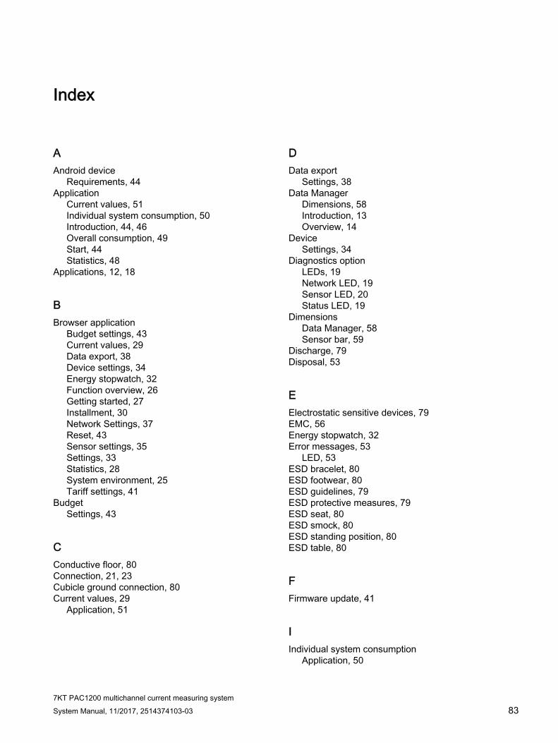
7KT PAC1200 multichannel current measuring system System Manual, 11/2017, 2514374103-03 83
Index
A Android device
Requirements, 44 Application
Current values, 51 Individual system consumption, 50 Introduction, 44, 46 Overall consumption, 49 Start, 44 Statistics, 48
Applications, 12, 18
B Browser application
Budget settings, 43 Current values, 29 Data export, 38 Device settings, 34 Energy stopwatch, 32 Function overview, 26 Getting started, 27 Installment, 30 Network Settings, 37 Reset, 43 Sensor settings, 35 Settings, 33 Statistics, 28 System environment, 25 Tariff settings, 41
Budget Settings, 43
C Conductive floor, 80 Connection, 21, 23 Cubicle ground connection, 80 Current values, 29
Application, 51
D Data export
Settings, 38 Data Manager
Dimensions, 58 Introduction, 13 Overview, 14
Device Settings, 34
Diagnostics option LEDs, 19 Network LED, 19 Sensor LED, 20 Status LED, 19
Dimensions Data Manager, 58 Sensor bar, 59
Discharge, 79 Disposal, 53
E Electrostatic sensitive devices, 79 EMC, 56 Energy stopwatch, 32 Error messages, 53
LED, 53 ESD bracelet, 80 ESD footwear, 80 ESD guidelines, 79 ESD protective measures, 79 ESD seat, 80 ESD smock, 80 ESD standing position, 80 ESD table, 80
F Firmware update, 41
I Individual system consumption
Application, 50

Index
7KT PAC1200 multichannel current measuring system 84 System Manual, 11/2017, 2514374103-03
Installment, 30 Intrinsic consumption, 55 Introduction
Application, 44 iOS device
Requirements, 44
N Network
Settings, 37
O Overall consumption
Application, 49
P Power supply, 23 Process data, 55
R Requirements
Android device, 44 iOS device, 44
Reset Settings, 43
S Sensor
Overview, 17 Settings, 35
Sensor bar Dimensions, 59 Overview, 16
Settings Background information, 33 Browser application, 33 Budget, 43 Data export, 38 Device, 34 Network, 37 Reset, 43 Sensor, 35 Start-up, 26 System environment, 25 Tariff, 41
Start-up Settings, 26
Statistics, 28 Application, 48
Storage, 79 System environment, 20
Browser application, 25 Settings, 25
T Tariff
Settings, 41 Technical specifications, 55
Intrinsic consumption, 55 Measuring accuracy, 56 Mounting, 55 Process data, 55 RS 485 interface, 57 Voltage and current inputs, 55
Transport, 79
V Voltage and current inputs, 55


![FLOW TEMP. CONTROLLER [MASTER] (Cased) PAC-IF051B-E PAC-IF052B-E FLOW TEMP. CONTROLLER ... · 2013. 2. 12. · PAC-IF051B-E PAC-IF052B-E FLOW TEMP. CONTROLLER [SLAVE] (Cased) PAC-SIF051B-E](https://img.pdfslide.us/doc/110x75/612d85651ecc515869423db7/flow-temp-controller-master-cased-pac-if051b-e-pac-if052b-e-flow-temp-controller.jpg)