Embed Size (px)
Citation preview

7 9 0 8 / 7 9 1 6S y s t e m 9 0 0 0 B a c k p l a n e
U n i v e r s a l w i r i n g m a n u a l a n d I / O c a r d r e f e r e n c e l i s t
N o . 7 9 0 0 U W M 1 0 2 _ U K
1701
PR electronics A/S tilbyder et bredt program af analoge og digitale signalbehandlingsmoduler til industriel automation. Programmet består af Isolatorer, Displays, Ex-barrierer, Temperaturtransmittere, Multifunktionelle transmittere mfl. Vi har modulerne, du kan stole på i selv barske miljøer med elektrisk støj, vibrationer og tempera-turudsving, og alle produkter opfylder de strengeste internationale standarder. Vores motto »Signals the Best« er indbegrebet af denne filosofi – og din garanti for kvalitet.
PR electronics A/S offers a wide range of analog and digital signal conditioning devices for industrial automation. The product range includes Isolators, Displays, I.S. Interfaces, Temperature Transmitters, and Multifunctional Devices. You can trust our products in the most extreme environments with electrical noise, vibrations and temperature fluctuations, and all products comply with the most exacting international standards. »Signals the Best« is the epitome of our philosophy – and your guarantee for quality.
PR electronics A/S offre une large gamme de produits pour le traite-ment des signaux analogiques et numériques dans tous les domaines industriels. La gamme de produits s’étend des transmetteurs de température aux afficheurs, des isolateurs aux interfaces SI, jusqu’aux modules multifonctions. Vous pouvez compter sur nos produits même dans les conditions d’utilisation sévères, p.ex. bruit électrique, vibrations et fluctuations de température. Tous nos produits sont conformes aux normes internationales les plus strictes. Notre devise »SIGNALS the BEST« c’est notre ligne de conduite - et pour vous l’assurance de la meilleure qualité.
PR electronics A/S verfügt über ein breites Produktprogramm an analogen und digitalen Signalverarbeitungsgeräte für die in-dustrielle Automatisierung. Dieses Programm umfasst Displays, Temperaturtransmitter, Ex- und galvanische Signaltrenner, und Multifunktionelle Geräte. Sie können unsere Geräte auch unter extremen Einsatzbedingungen wie elektrisches Rauschen, Erschütterungen und Temperaturschwingungen vertrauen, und alle Produkte von PR electronics werden in Überein stimmung mit den strengsten internationalen Normen produziert. »Signals the Best« ist Ihre Garantie für Qualität!
DK
UK
FR
DE
2 7900 UWM102-UK
7900UWM102-UK 3
SYSTEM 9000 BACKPLANEUNIVERSAL WIRING MANUAL
AND I/O CARD REFERENCE LISTCONTENTS
Intro ............................................................................................................................. 4Order code............................................................................................................ 4Supply and status relay connections ........................................................ 5Universal backplane 8 modules - 8/16 x I/O ......................................... 7Universal backplane 16 modules - 16/32 x I/O ................................... 9
Appendix ................................................................................................................... 12Suggested system cable for Universal Backplanes ............................ 139106 AI I.S. or non-I.S. isolation barrier - wiring connections ........ 149107 AO I.S. or non-I.S. isolation barrier - wiring connections ...... 159113 AI I.S. or non-I.S. isolation barrier - wiring connections ........ 169116 AI I.S. or non-I.S. isolation barrier - wiring connections ........ 179202 AO I.S. or non-I.S. isolation barrier - wiring connections ...... 189203 AI I.S. or non-I.S. isolation barrier - wiring connections ........ 19
4 7900 UWM102-UK
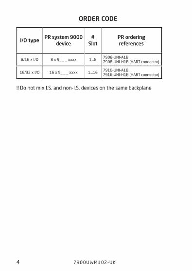
ORDER CODE
I/O typePR system 9000
device#
Slot PR ordering references
8/16 x I/O 8 x 9_ _ _ xxxx 1...8 7908-UNI-A1B7908-UNI-H1B (HART connector)
16/32 x I/O 16 x 9_ _ _ xxxx 1...16 7916-UNI-A1B7916-UNI-H1B (HART connector)
INTRO
Order code
!! Do not mix I.S. and non-I.S. devices on the same backplane
7900UWM102-UK 5
CN 1
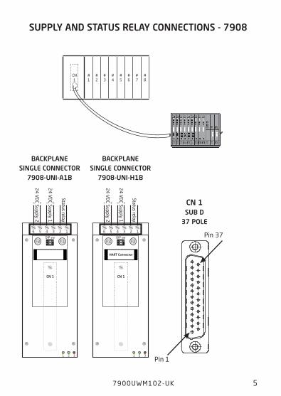
SUPPLY AND STATUS RELAY CONNECTIONS - 7908
CN 1
12
ON
++ --
1 2 3
F 1DIP sw
F 2
35 126 4
HART Connector
24
VD
C Supply 2
24
VD
C Supply 1
Status relay
CN 1SUB D
37 POLE
Pin 1
Pin 37
BACKPLANE SINGLE CONNECTOR
7908-UNI-H1B
Supply and status relay connections
CN 1
12
ON
++ --
1 2 3
F 1DIP sw
F 2
35 126 4
24
VD
C Supply 2
24
VD
C Supply 1
Status relay
BACKPLANE SINGLE CONNECTOR
7908-UNI-A1B
# 1
# 2
# 3
# 4
# 5
# 6
# 7
# 8
6 7900 UWM102-UK
# 1
# 2
# 3
# 4
# 5
# 6
# 7
# 8
# 9
# 10
# 11
# 12
# 13
# 14
# 15
# 16
CN 2
CN 1
12
ON
++ --
1 2 3
F 1DIP sw
CN 1CN 2
F 2
35 126 4
HART Connector
24
VD
C Supply 2
24
VD
C Supply 1
Status relay
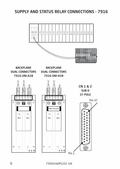
CN 1 & 2SUB D
37 POLE
Pin 1
Pin 37
BACKPLANE DUAL CONNECTORS
7916-UNI-H1B
12
ON
++ --
1 2 3
F 1DIP sw
CN 1CN 2
F 2
35 126 4
24
VD
C Supply 2
24
VD
C Supply 1
Status relay
BACKPLANE DUAL CONNECTORS
7916-UNI-A1B
SUPPLY AND STATUS RELAY CONNECTIONS - 7916
7900UWM102-UK 7
Block diagram for universal backplane 8 modules - 8/16 x I/O
Universal backplane 8 modules - 8/16 x I/O
The wiring shown in the table on the following page is 1:1 wiring with no components mounted in the signal chain.
Supported I/O modules:
9106xxx, 9107xx, 9113xx, 9116xx, 9202xxx and 9203xxxx.
Please note:
Check the module manual for correct Input/Output signal wiring.

8 7900 UWM102-UK
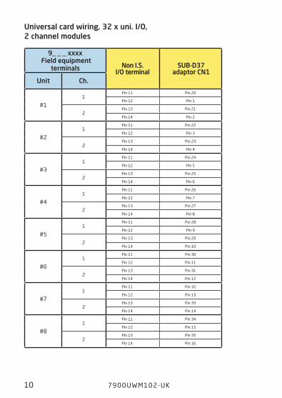
9_ _ _ xxxx Field equipment
terminals Non I.S. I/O terminal
SUB-D37 adaptor CN1
Unit Ch.
#11
Pin 11 Pin 20
Pin 12 Pin 1
2Pin 13 Pin 21
Pin 14 Pin 2
#21
Pin 11 Pin 22
Pin 12 Pin 3
2Pin 13 Pin 23
Pin 14 Pin 4
#31
Pin 11 Pin 24
Pin 12 Pin 5
2Pin 13 Pin 25
Pin 14 Pin 6
#41
Pin 11 Pin 26
Pin 12 Pin 7
2Pin 13 Pin 27
Pin 14 Pin 8
#51
Pin 11 Pin 28
Pin 12 Pin 9
2Pin 13 Pin 29
Pin 14 Pin 10
#61
Pin 11 Pin 30
Pin 12 Pin 11
2Pin 13 Pin 31
Pin 14 Pin 12
#71
Pin 11 Pin 32
Pin 12 Pin 13
2Pin 13 Pin 33
Pin 14 Pin 14
#81
Pin 11 Pin 34
Pin 12 Pin 15
2Pin 13 Pin 35
Pin 14 Pin 16
Universal card wiring, 16 x uni. I/O, 2 channel modules
7900UWM102-UK 9
Block diagram for universal backplane 16 modules - 16/32 x I/O
Universal backplane 16 modules - 16/32 x I/O
The wiring shown in the tables on the following pages is 1:1 wiring with no components mounted in the signal chain.
Supported I/O modules:
9106xxx, 9107xx, 9113xx, 9116xx, 9202xxx and 9203xxxx.
Please note:
Check the module manual for correct Input/Output signal wiring.
10 7900 UWM102-UK
9_ _ _ xxxx Field equipment
terminals Non I.S. I/O terminal
SUB-D37 adaptor CN1
Unit Ch.
#11
Pin 11 Pin 20
Pin 12 Pin 1
2Pin 13 Pin 21
Pin 14 Pin 2
#21
Pin 11 Pin 22
Pin 12 Pin 3
2Pin 13 Pin 23
Pin 14 Pin 4
#31
Pin 11 Pin 24
Pin 12 Pin 5
2Pin 13 Pin 25
Pin 14 Pin 6
#41
Pin 11 Pin 26
Pin 12 Pin 7
2Pin 13 Pin 27
Pin 14 Pin 8
#51
Pin 11 Pin 28
Pin 12 Pin 9
2Pin 13 Pin 29
Pin 14 Pin 10
#61
Pin 11 Pin 30
Pin 12 Pin 11
2Pin 13 Pin 31
Pin 14 Pin 12
#71
Pin 11 Pin 32
Pin 12 Pin 13
2Pin 13 Pin 33
Pin 14 Pin 14
#81
Pin 11 Pin 34
Pin 12 Pin 15
2Pin 13 Pin 35
Pin 14 Pin 16
Universal card wiring, 32 x uni. I/O, 2 channel modules
7900UWM102-UK 11
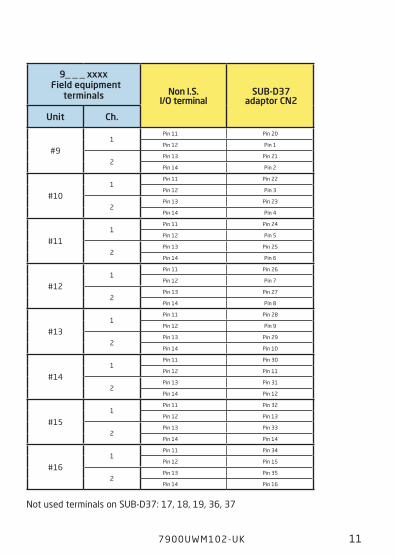
Not used terminals on SUB-D37: 17, 18, 19, 36, 37
9_ _ _ xxxx Field equipment
terminals Non I.S. I/O terminal
SUB-D37 adaptor CN2
Unit Ch.
#91
Pin 11 Pin 20
Pin 12 Pin 1
2Pin 13 Pin 21
Pin 14 Pin 2
#101
Pin 11 Pin 22
Pin 12 Pin 3
2Pin 13 Pin 23
Pin 14 Pin 4
#111
Pin 11 Pin 24
Pin 12 Pin 5
2Pin 13 Pin 25
Pin 14 Pin 6
#121
Pin 11 Pin 26
Pin 12 Pin 7
2Pin 13 Pin 27
Pin 14 Pin 8
#131
Pin 11 Pin 28
Pin 12 Pin 9
2Pin 13 Pin 29
Pin 14 Pin 10
#141
Pin 11 Pin 30
Pin 12 Pin 11
2Pin 13 Pin 31
Pin 14 Pin 12
#151
Pin 11 Pin 32
Pin 12 Pin 13
2Pin 13 Pin 33
Pin 14 Pin 14
#161
Pin 11 Pin 34
Pin 12 Pin 15
2Pin 13 Pin 35
Pin 14 Pin 16

12 7900 UWM102-UK
APPENDIXBACKPLANE TO I/O CARD
CABLE REFERENCES &
9106, 9107, 9113, 9116, 9202, 9203WIRING CONNECTION
7900UWM102-UK 13
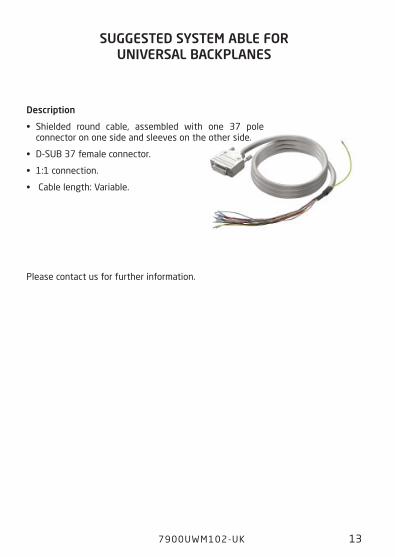
SUGGESTED SYSTEM ABLE FOR UNIVERSAL BACKPLANES
Suggested system cable for Universal Backplanes
Description
• Shielded round cable, assembled with one 37 pole connector on one side and sleeves on the other side.
• D-SUB 37 female connector.
• 1:1 connection.
• Cable length: Variable.
Please contact us for further information.
CO
MM
UN
ICA
TIO
N F
OU
ND
AT
ION
Tx-
+
-
Tx+
-
+
-
12
11
14
13C
OM
MU
NIC
AT
ION
FO
UN
DA
TIO
N
mA+
-
mA
+
12
11
14
13 CO
MM
UN
ICA
TIO
N F
OU
ND
AT
ION
mA+
-
mA
+
44
43
42
41
44
43
42
41
54
53
52
51
14 7900 UWM102-UK
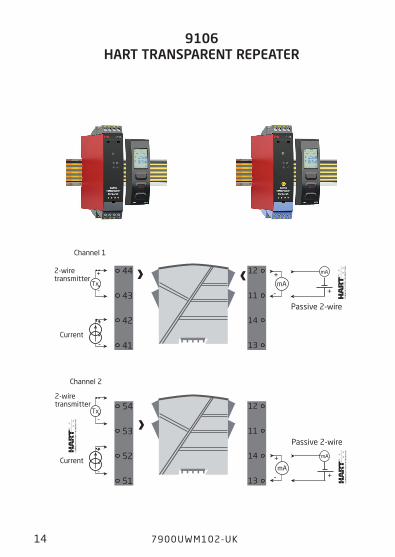
Channel 2
Channel 1
2-wire transmitter
Current
Current
2-wire transmitter
9106 HART TRANSPARENT REPEATER
9106 AI I.S. or non-I.S. isolation barrier - wiring connections
Passive 2-wire
Passive 2-wire
12
11
14
13
CO
MM
UN
ICA
TIO
N F
OU
ND
AT
ION
+
-
44
43
42
41
44
43
42
41
12
11
14
13 CO
MM
UN
ICA
TIO
N F
OU
ND
AT
ION
+
-
54
53
52
51
7900UWM102-UK 15
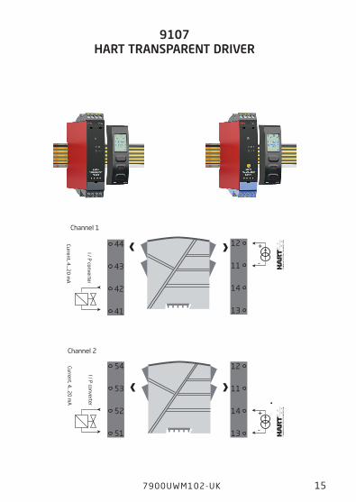
Channel 2
Channel 1
I / P converter
Current, 4...2
0 m
A
I / P converter
Current, 4...2
0 m
A
9107 HART TRANSPARENT DRIVER
9107 AO I.S. or non-I.S. isolation barrier - wiring connections
-
+
-
+
mA
mA
44
43
42
41
44
43
42
41
14
13
12
11
+
- +
mA
mA44
43
42
41
54
53
52
51
14
13
12
11
+
- +
16 7900 UWM102-UK
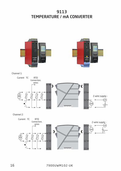
9113 TEMPERATURE / mA CONVERTER
RTD Connection,
wires
Current TC
Channel 1:
Channel 2:
RTD Connection,
wires
Current TC
9113 AI I.S. or non-I.S. isolation barrier - wiring connections
2-wire supply -
2-wire supply -
*
44
43
42
41
44
43
42
41
12
11
14
13
mA
mA+
- +
7900UWM102-UK 17
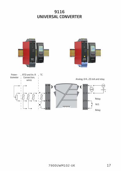
9116 UNIVERSAL CONVERTER
9116 AI I.S. or non-I.S. isolation barrier - wiring connections
Poten- tiometer
TCRTD and lin. RConnection,
wires Analog, 0/4...20 mA and relay
Relay
Relay
N.O.
NAMUR
44
43
42
41
NAMUR
54
53
52
51
Rp
Rs
Rp
Rp
Rs
Rp
+
-
+
-
Rp = 15 kΩ Rs = 750 Ω
Rp = 15 kΩ Rs = 750 Ω
Opto -
Opto +
Opto +14
13
12
11
Opto -
14
13
12
11
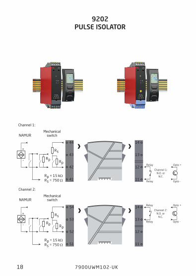
18 7900 UWM102-UK
Mechanical switch
Channel 1:
Channel 2:
Mechanical switch
9202 PULSE ISOLATOR
9202 AO I.S. or non-I.S. isolation barrier - wiring connections
Relay
Relay
Channel 1: N.O. or
N.C.
Relay
Relay
Channel 2: N.O. or
N.C.
54
53
52
51
44
43
42
41
V+ V+
V+ V+
14
13
12
11
14
13
12
11
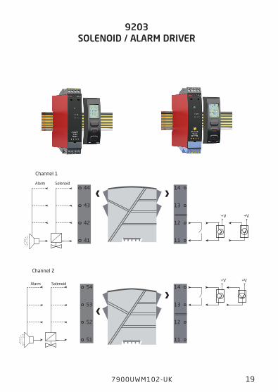
7900UWM102-UK 19
Channel 2
SolenoidAlarm
Channel 1
SolenoidAlarm
9203 SOLENOID / ALARM DRIVER
9203 AI I.S. or non-I.S. isolation barrier - wiring connections
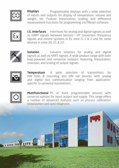
Programmable displays with a wide selection of inputs and outputs for display of temperature, volume and weight, etc. Feature linearization, scaling, and difference measurement functions for programming via PReset software.
Displays
A wide selection of transmitters for DIN form B mounting and DIN rail devices with analog and digital bus communication ranging from application- specific to universal transmitters.
Temperature
Galvanic isolators for analog and digital signals as well as HART signals. A wide product range with both loop-powered and universal isolators featuring linearization, inversion, and scaling of output signals.
Isolation
Interfaces for analog and digital signals as well as HART signals between sensors / I/P converters /frequency signals and control systems in Ex zone 0, 1 & 2 and for some devices in zone 20, 21 & 22.
I.S. interfaces
PC or front programmable devices with universal options for input, output and supply. This range offers a number of advanced features such as process calibration, linearization and auto-diagnosis.
Multifunctional

www.prelectronics.fr [email protected]
www.prelectronics.de [email protected]
www.prelectronics.es [email protected]
www.prelectronics.it [email protected]
www.prelectronics.se [email protected]
www.prelectronics.com [email protected]
www.prelectronics.com [email protected]
www.prelectronics.cn [email protected]
www.prelectronics.be [email protected]
Head officeDenmark www.prelectronics.comPR electronics A/S [email protected] 10 tel. +45 86 37 26 77DK-8410 Rønde fax +45 86 37 30 85