Embed Size (px)
Citation preview

®
787ProcessMeter
November 2000 Rev. 1, 12/01© 2000, 2001 Fluke Corporation. All rights reserved. Printed in U.S.A.All product names are trademarks of their respective companies.
Product Overview

iii
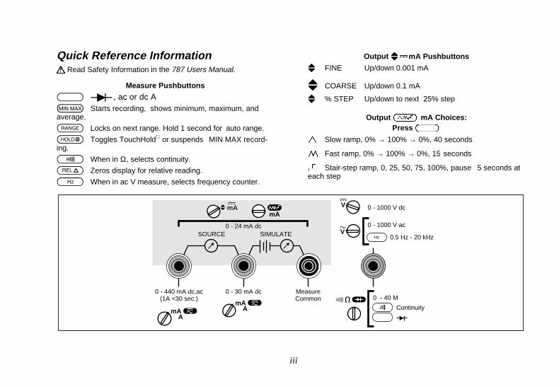
Quick Reference Information! Read Safety Information in the 787 Users Manual.
Measure Pushbuttons
U D, ac or dc AM Starts recording, shows minimum, maximum, andaverage.
K Locks on next range. Hold 1 second for auto range.
I Toggles TouchHold or suspends MIN MAX record-ing.
T When in Ω, selects continuity.
C Zeros display for relative reading.
F When in ac V measure, selects frequency counter.
Output [dmA Pushbuttons
[ FINE Up/down 0.001 mA
[ COARSE Up/down 0.1 mA
[ % STEP Up/down to next 25% step
Output J mA Choices:Press U
E Slow ramp, 0% → 100% → 0%, 40 seconds
P Fast ramp, 0% → 100% → 0%, 15 seconds
N Stair-step ramp, 0, 25, 50, 75, 100%, pause 5 seconds ateach step
MeasureCommon
0 - 30 mA dc
SOURCE SIMULATE
0 - 440 mA dc,ac(1A <30 sec.)
mA A
mAmA
0 - 40 M
Continuity
0 - 1000 V ac
0 - 1000 V dcV
0.5 Hz - 20 kHzV
Hz
mA A
0 - 24 mA dc
LIMITED WARRANTY & LIMITATION OF LIABILITY
This Fluke product will be free from defects in material and workmanship for three years from the date of purchase. Thiswarranty does not cover disposable batteries or damage from accident, neglect, misuse or abnormal conditions of operationor handling. Resellers are not authorized to extend any other warranty on Fluke’s behalf. To obtain service during the war-ranty period, send your defective meter to the nearest Fluke Authorized Service Center with a description of the problem.
THIS WARRANTY IS YOUR ONLY REMEDY. NO OTHER WARRANTIES, SUCH AS FITNESS FOR A PARTICULARPURPOSE, ARE EXPRESSED OR IMPLIED. FLUKE IS NOT LIABLE FOR ANY SPECIAL, INDIRECT, INCIDENTAL ORCONSEQUENTIAL DAMAGES OR LOSSES, ARISING FROM ANY CAUSE OR THEORY.
Since some states or countries do not allow the exclusion or limitation of an implied warranty or of incidental or consequen-tial damages, this limitation of liability may not apply to you.
Fluke Corporation Fluke Europe B.V.P.O. Box 9090 P.O. Box 1186Everett, WA 5602 B.D. Eindhoven98206-9090 USA The Netherlands
1
ProcessMeter
IntroductionWWarning
Read “Safety Information” before you use themeter.
Your Fluke 787 ProcessMeter (referred to as “themeter”) is a handheld, battery-operated tool for measuringelectrical parameters and supplying steady or rampingcurrent to test process instruments. It has all the featuresof a digital multimeter, plus current output capability.
Your meter is shipped with a Flex-StandTM holster, one setof TL75 test leads, one set of AC70A Alligator Clips, thismanual, and a CD-ROM containing the Users Manual. Ifthe meter is damaged or something is missing, contact theplace of purchase immediately.
Contact your Fluke distributor for information about DMMaccessories. To order replacement parts or spares, seeTable 7 near the end of this manual.
Accessing the Users ManualThe 787 Users Manual is available on the 787 CD-ROMshipped with your ProcessMeter.
787Product Overview
2
Contacting FlukeTo order accessories, receive operating assistance, or getthe location of the nearest Fluke distributor or ServiceCenter, call:
USA : 1-888-99-FLUKE (1-888-993-5853)Canada: 1-800-36-FLUKE (1-800-363-5853)Europe: +31 402-678-200Japan: +81-3-3434-0181Singapore: +65-738-5655Anywhere in the world: +1-425-446-5500
Address correspondence to:
Fluke Corporation Fluke Europe B.V.P.O. Box 9090, P.O. Box 1186,Everett, WA 98206-9090 5602 BD EindhovenUSA The Netherlands
Or visit us on the World Wide Web: www.fluke.com
Safety InformationThe meter complies with IEC1010-1, ANSI/ISA S82.01-1994 and CAN/CSA C22.2 No. 1010.1-92 OvervoltageCategory III. Use the meter only as specified in thismanual, otherwise the protection provided by the metermay be impaired.
A Warning identifies conditions and actions that posehazard(s) to the user; a Caution identifies conditions andactions that may damage the meter or the equipmentunder test.
International symbols used on the meter and in thismanual are explained in Table 1.
WWarningTo avoid possible electric shock or personalinjury:
• Do not use the meter if it is damaged.Before you use the meter, inspect thecase. Look for cracks or missing plastic.Pay particular attention to the insulationsurrounding the connectors.
ProcessMeterSafety Information
3
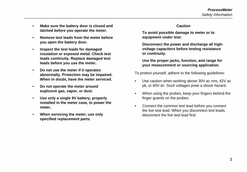
• Make sure the battery door is closed andlatched before you operate the meter.
• Remove test leads from the meter beforeyou open the battery door.
• Inspect the test leads for damagedinsulation or exposed metal. Check testleads continuity. Replace damaged testleads before you use the meter.
• Do not use the meter if it operatesabnormally. Protection may be impaired.When in doubt, have the meter serviced.
• Do not operate the meter aroundexplosive gas, vapor, or dust.
• Use only a single 9V battery, properlyinstalled in the meter case, to power themeter.
• When servicing the meter, use onlyspecified replacement parts.
Caution
To avoid possible damage to meter or toequipment under test:
Disconnect the power and discharge all high-voltage capacitors before testing resistanceor continuity.
Use the proper jacks, function, and range foryour measurement or sourcing application.
To protect yourself, adhere to the following guidelines:
• Use caution when working above 30V ac rms, 42V acpk, or 60V dc. Such voltages pose a shock hazard.
• When using the probes, keep your fingers behind thefinger guards on the probes.
• Connect the common test lead before you connectthe live test lead. When you disconnect test leads,disconnect the live test lead first.
787Product Overview
4
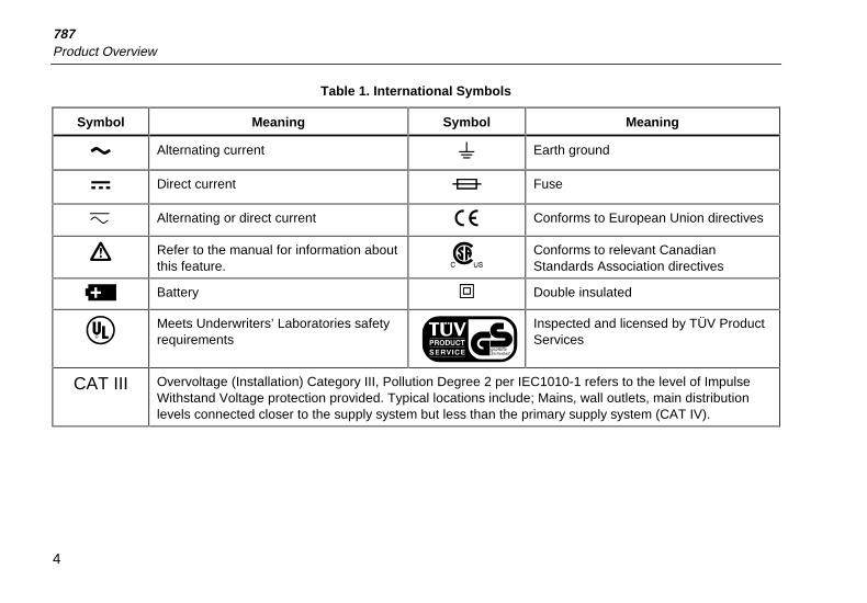
Table 1. International Symbols
Symbol Meaning Symbol Meaning
Alternating current Earth ground
Direct current Fuse
c Alternating or direct current Conforms to European Union directives
Refer to the manual for information aboutthis feature.
Conforms to relevant CanadianStandards Association directives
Battery T Double insulated
Meets Underwriters’ Laboratories safetyrequirements
Inspected and licensed by TÜV ProductServices
CAT III Overvoltage (Installation) Category III, Pollution Degree 2 per IEC1010-1 refers to the level of ImpulseWithstand Voltage protection provided. Typical locations include; Mains, wall outlets, main distributionlevels connected closer to the supply system but less than the primary supply system (CAT IV).
ProcessMeterGetting Acquainted with the Meter
5
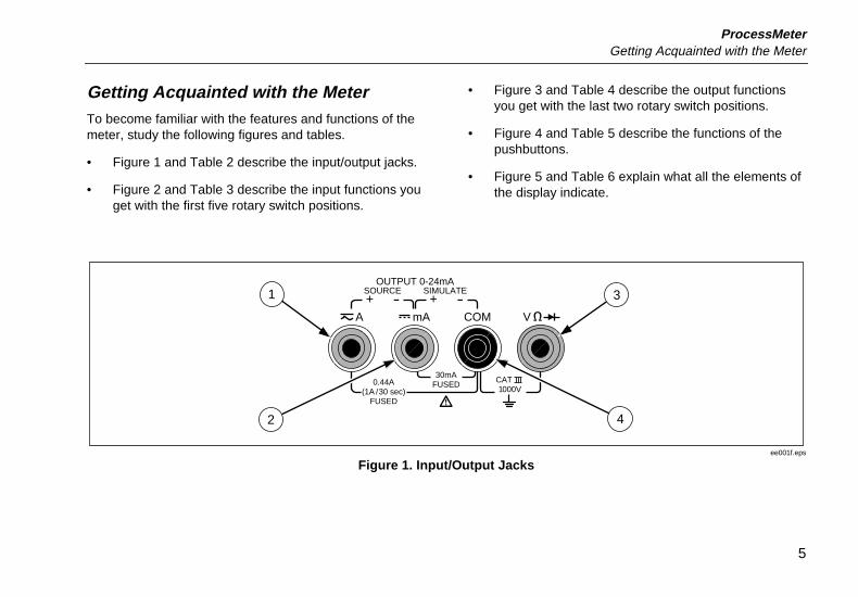
Getting Acquainted with the MeterTo become familiar with the features and functions of themeter, study the following figures and tables.
• Figure 1 and Table 2 describe the input/output jacks.
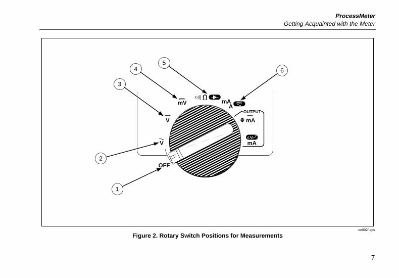
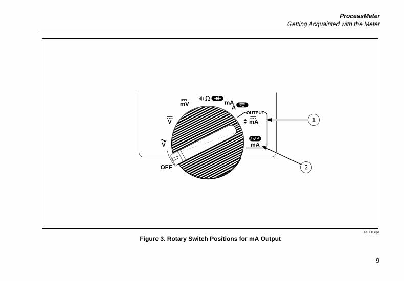
• Figure 2 and Table 3 describe the input functions youget with the first five rotary switch positions.
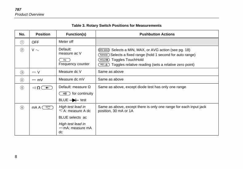
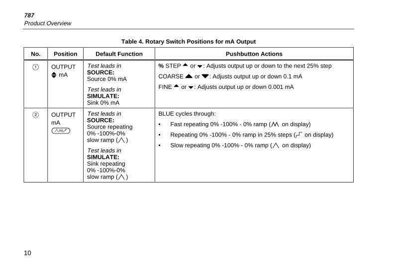
• Figure 3 and Table 4 describe the output functionsyou get with the last two rotary switch positions.
• Figure 4 and Table 5 describe the functions of thepushbuttons.
• Figure 5 and Table 6 explain what all the elements ofthe display indicate.
A mA COM V
1000V
30mAFUSED0.44A
(1A /30 sec)FUSED
OUTPUT 0-24mA SOURCE SIMULATE+ +
CAT
1
2
3
4
ee001f.eps
Figure 1. Input/Output Jacks
787Product Overview
6
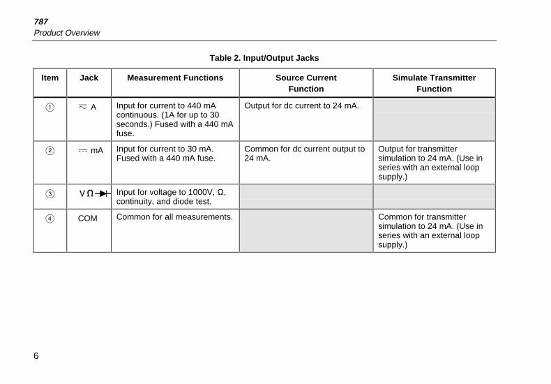
Table 2. Input/Output Jacks
Item Jack Measurement Functions Source CurrentFunction
Simulate TransmitterFunction
A c A Input for current to 440 mAcontinuous. (1A for up to 30seconds.) Fused with a 440 mAfuse.
Output for dc current to 24 mA.
B d mA Input for current to 30 mA.Fused with a 440 mA fuse.
Common for dc current output to24 mA.
Output for transmittersimulation to 24 mA. (Use inseries with an external loopsupply.)
C V Input for voltage to 1000V, Ω,continuity, and diode test.
D COM Common for all measurements. Common for transmittersimulation to 24 mA. (Use inseries with an external loopsupply.)
ProcessMeterGetting Acquainted with the Meter
7
4
3
5
1
2
6
OFF
mA
mA A
mA
mV
V
V
OUTPUT
ee002f.eps
Figure 2. Rotary Switch Positions for Measurements
787Product Overview
8
Table 3. Rotary Switch Positions for Measurements
No. Position Function(s) Pushbutton Actions
A OFF Meter off
B V A Default:measure ac V
FFrequency counter
M Selects a MIN, MAX, or AVG action (see pg. 18)KSelects a fixed range (hold 1 second for auto range)I Toggles TouchHoldC Toggles relative reading (sets a relative zero point)
C d V Measure dc V Same as above
D d mV Measure dc mV Same as above
E O Default: measure Ω
T for continuity
BLUE D test
Same as above, except diode test has only one range
F mA A L High test lead incA: measure A dc
BLUE selects ac
High test lead indmA: measure mAdc
Same as above, except there is only one range for each input jackposition, 30 mA or 1A
ProcessMeterGetting Acquainted with the Meter
9
OFF
mA
mA A
mA
mV
V
V
OUTPUT
2
1
ee008.eps
Figure 3. Rotary Switch Positions for mA Output
787Product Overview
10
Table 4. Rotary Switch Positions for mA Output
No. Position Default Function Pushbutton Actions
A OUTPUT[ mA
Test leads inSOURCE:Source 0% mA
Test leads inSIMULATE:Sink 0% mA
% STEP X or W: Adjusts output up or down to the next 25% step
COARSE Z or Y: Adjusts output up or down 0.1 mA
FINE X or W: Adjusts output up or down 0.001 mA
B OUTPUTmAJ
Test leads inSOURCE:Source repeating0% -100%-0%slow ramp (E)
Test leads inSIMULATE:Sink repeating0% -100%-0%slow ramp (E)
BLUE cycles through:
• Fast repeating 0% -100% - 0% ramp (P on display)
• Repeating 0% -100% - 0% ramp in 25% steps (N on display)
• Slow repeating 0% -100% - 0% ramp (E on display)
ProcessMeterGetting Acquainted with the Meter
11
2 3
1
54
678
MIN MAX RANGE HOLD H
REL Hz
% STEP COARSE FINE
ee003f.eps
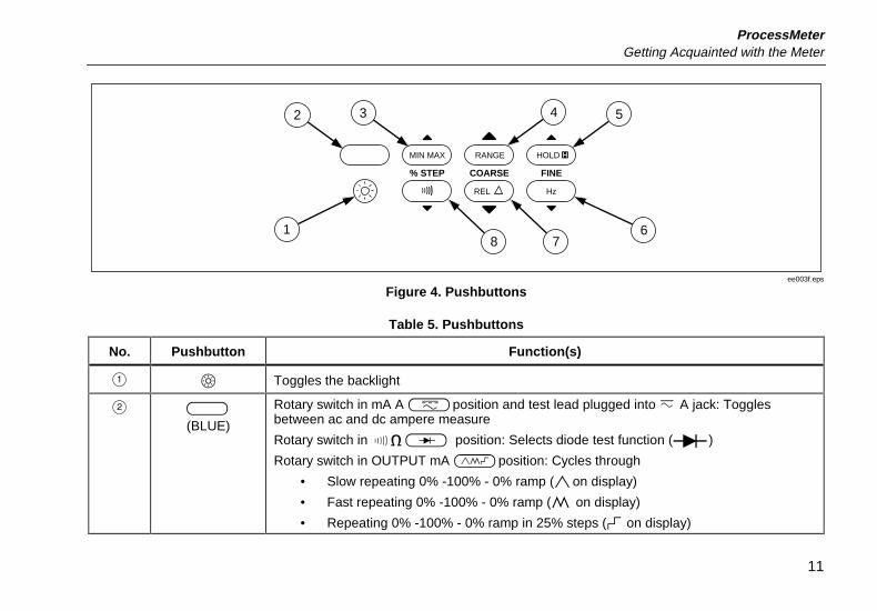
Figure 4. Pushbuttons
Table 5. Pushbuttons
No. Pushbutton Function(s)
A b Toggles the backlight
B U(BLUE)
Rotary switch in mA A Lposition and test lead plugged into c A jack: Togglesbetween ac and dc ampere measure
Rotary switch in O position: Selects diode test function (D)
Rotary switch in OUTPUT mA Jposition: Cycles through
• Slow repeating 0% -100% - 0% ramp (Eon display)
• Fast repeating 0% -100% - 0% ramp (P on display)
• Repeating 0% -100% - 0% ramp in 25% steps (N on display)
787Product Overview
12
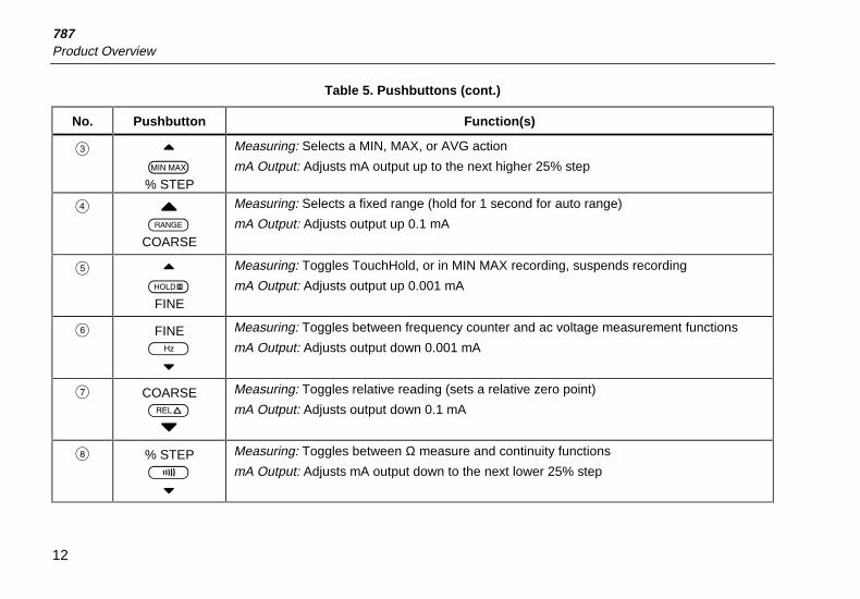
Table 5. Pushbuttons (cont.)
No. Pushbutton Function(s)
C XM% STEP
Measuring: Selects a MIN, MAX, or AVG action
mA Output: Adjusts mA output up to the next higher 25% step
D ZK
COARSE
Measuring: Selects a fixed range (hold for 1 second for auto range)
mA Output: Adjusts output up 0.1 mA
E XIFINE
Measuring: Toggles TouchHold, or in MIN MAX recording, suspends recording
mA Output: Adjusts output up 0.001 mA
F FINEF
W
Measuring: Toggles between frequency counter and ac voltage measurement functions
mA Output: Adjusts output down 0.001 mA
G COARSEC
Y
Measuring: Toggles relative reading (sets a relative zero point)
mA Output: Adjusts output down 0.1 mA
H % STEPT
W
Measuring: Toggles between Ω measure and continuity functions
mA Output: Adjusts mA output down to the next lower 25% step
ProcessMeterGetting Acquainted with the Meter
13
1
5
3
2
4
86 7 9
10
12
11
ee004f.eps
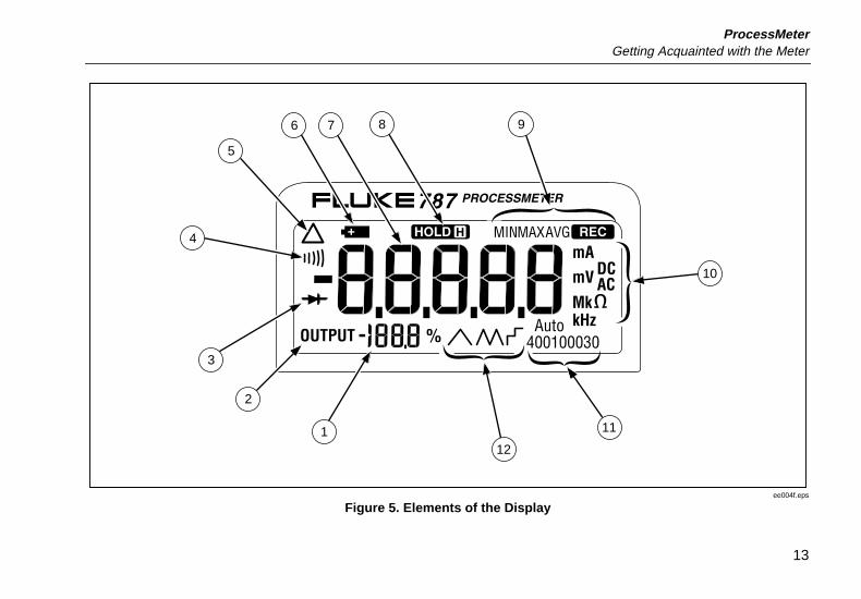
Figure 5. Elements of the Display
787Product Overview
14
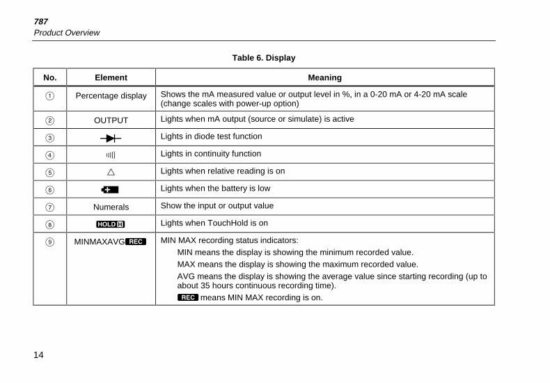
Table 6. Display
No. Element Meaning
A Percentage display Shows the mA measured value or output level in %, in a 0-20 mA or 4-20 mA scale(change scales with power-up option)
B OUTPUT Lights when mA output (source or simulate) is active
C D Lights in diode test function
D S Lights in continuity function
E Q Lights when relative reading is on
F B Lights when the battery is low
G Numerals Show the input or output value
H H Lights when TouchHold is on
I MINMAXAVGR MIN MAX recording status indicators:MIN means the display is showing the minimum recorded value.MAX means the display is showing the maximum recorded value.AVG means the display is showing the average value since starting recording (up toabout 35 hours continuous recording time).Rmeans MIN MAX recording is on.
ProcessMeterGetting Acquainted with the Meter
15
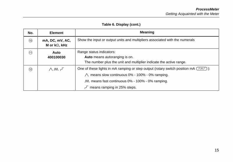
Table 6. Display (cont.)
No. Element Meaning
J mA, DC, mV, AC,M or kΩ, kHz
Show the input or output units and multipliers associated with the numerals
K Auto400100030
Range status indicators:Auto means autoranging is on.The number plus the unit and multiplier indicate the active range.
L EP N One of these lights in mA ramping or step output (rotary switch position mA J):
E means slow continuous 0% - 100% - 0% ramping.
P means fast continuous 0% - 100% - 0% ramping.
N means ramping in 25% steps.
787Product Overview
16
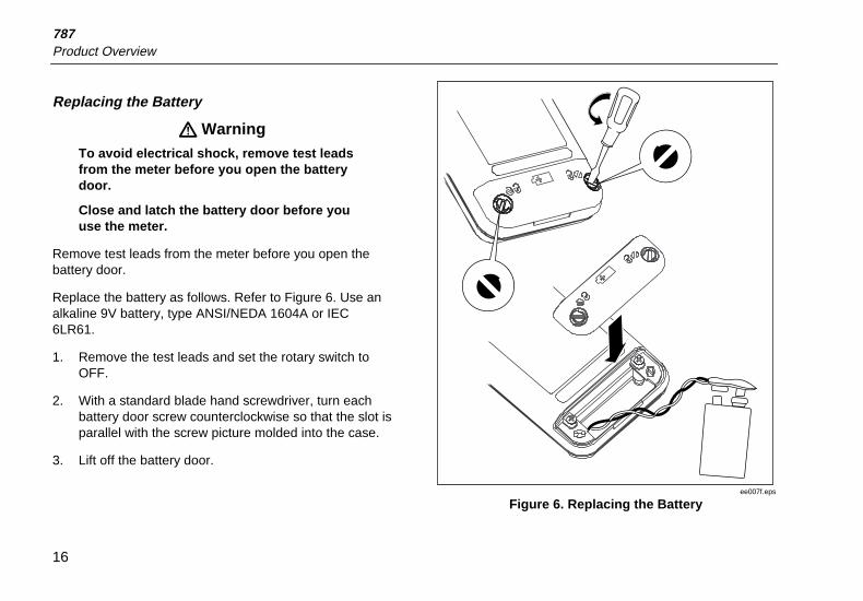
Replacing the Battery
! WarningTo avoid electrical shock, remove test leadsfrom the meter before you open the batterydoor.
Close and latch the battery door before youuse the meter.
Remove test leads from the meter before you open thebattery door.
Replace the battery as follows. Refer to Figure 6. Use analkaline 9V battery, type ANSI/NEDA 1604A or IEC6LR61.
1. Remove the test leads and set the rotary switch toOFF.
2. With a standard blade hand screwdriver, turn eachbattery door screw counterclockwise so that the slot isparallel with the screw picture molded into the case.
3. Lift off the battery door.
ee007f.eps
Figure 6. Replacing the Battery
ProcessMeterGetting Acquainted with the Meter
17
Replacing a Fuse
! WarningTo avoid personal injury or damage to themeter, use only the specified replacementfuse, 440 mA 1000V fast-blow, Fluke PN943121.
Both current input jacks are fused with a separate 440 mAfuse. To determine if a fuse is blown:
1. Turn the rotary switch to mA A L.
2. Plug the black test lead into COM, and the red testlead into cA.
3. Using an ohmmeter, check the resistance betweenthe meter test leads. If the resistance is about 1Ω, thefuse is good. An open means the fuse is blown.
4. Move red test lead to dmA.
5. Using an ohmmeter, check the resistance betweenthe meter test leads. If the resistance is about 14Ω,the fuse is good. An open means the fuse is blown.
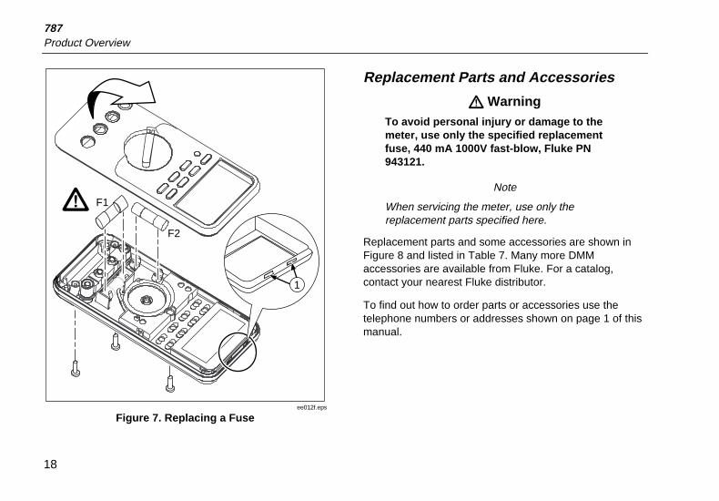
If a fuse is blown, replace it as follows. Refer to Figure 7as necessary:
1. Remove the test leads from the meter and turn therotary switch to OFF.
2. Remove the battery door.
3. Remove the three Phillips-head screws from the casebottom and turn the case over.
4. Gently lift the bottom of the front of the case (nearestthe input/output jacks) until the top unsnaps from therear half of the case.
5. Replace the blown fuse with the exact type specified:440 mA 1000V fast-blow fuse, Fluke PN 943121.Both fuses are the same type.
6. Make sure the rotary switch is in the OFF position.
7. Fit the top of case together, engaging the two snaps(item A). Make sure that the gasket is properlyseated.
8. Close the case and reinstall the three screws.
9. Replace the battery door.
787Product Overview
18
F1
F2
1
ee012f.eps
Figure 7. Replacing a Fuse
Replacement Parts and Accessories
! WarningTo avoid personal injury or damage to themeter, use only the specified replacementfuse, 440 mA 1000V fast-blow, Fluke PN943121.
Note
When servicing the meter, use only thereplacement parts specified here.
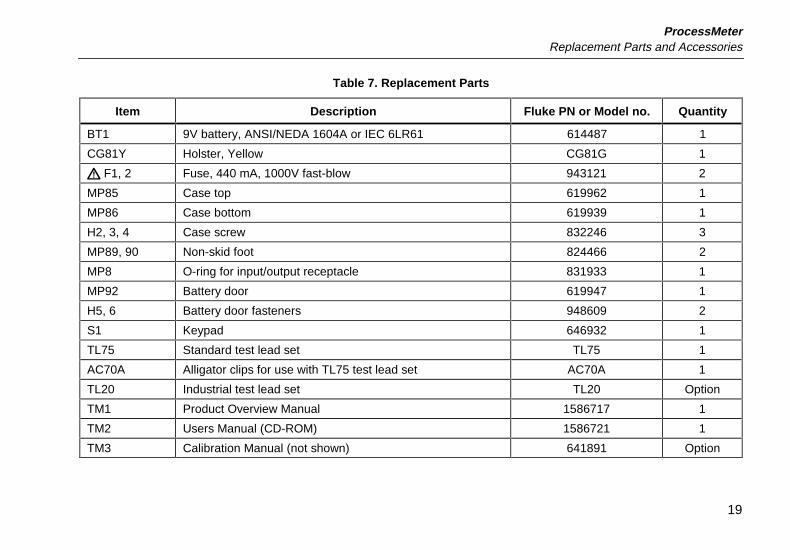
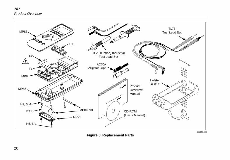
Replacement parts and some accessories are shown inFigure 8 and listed in Table 7. Many more DMMaccessories are available from Fluke. For a catalog,contact your nearest Fluke distributor.
To find out how to order parts or accessories use thetelephone numbers or addresses shown on page 1 of thismanual.
ProcessMeterReplacement Parts and Accessories
19
Table 7. Replacement Parts
Item Description Fluke PN or Model no. Quantity
BT1 9V battery, ANSI/NEDA 1604A or IEC 6LR61 614487 1
CG81Y Holster, Yellow CG81G 1
! F1, 2 Fuse, 440 mA, 1000V fast-blow 943121 2
MP85 Case top 619962 1
MP86 Case bottom 619939 1
H2, 3, 4 Case screw 832246 3
MP89, 90 Non-skid foot 824466 2
MP8 O-ring for input/output receptacle 831933 1
MP92 Battery door 619947 1
H5, 6 Battery door fasteners 948609 2
S1 Keypad 646932 1
TL75 Standard test lead set TL75 1
AC70A Alligator clips for use with TL75 test lead set AC70A 1
TL20 Industrial test lead set TL20 Option
TM1 Product Overview Manual 1586717 1
TM2 Users Manual (CD-ROM) 1586721 1
TM3 Calibration Manual (not shown) 641891 Option
787Product Overview
20
F2
F1
MP8
H2, 3, 4
BT1
H5, 6
MP85
MP86
HolsterCG81Y
AC70AAlligator Clips
TL20 (Option) Industrial Test Lead Set
S1
MP92
Product OverviewManual
CD-ROM(Users Manual)
TL75Test Lead Set
MP89, 90
ee015c.eps
Figure 8. Replacement Parts
ProcessMeterSpecifications
21
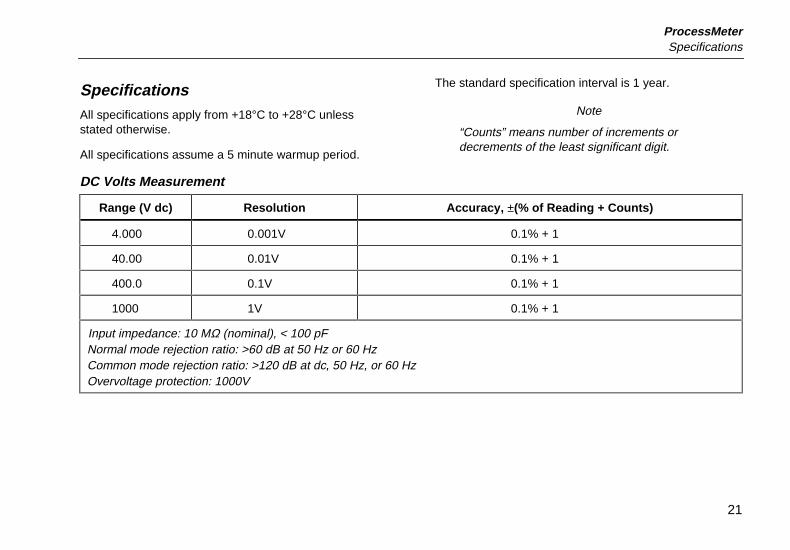
SpecificationsAll specifications apply from +18°C to +28°C unlessstated otherwise.
All specifications assume a 5 minute warmup period.
The standard specification interval is 1 year.
Note
“Counts” means number of increments ordecrements of the least significant digit.
DC Volts Measurement
Range (V dc) Resolution Accuracy, ±(% of Reading + Counts)
4.000 0.001V 0.1% + 1
40.00 0.01V 0.1% + 1
400.0 0.1V 0.1% + 1
1000 1V 0.1% + 1
Input impedance: 10 MΩ (nominal), < 100 pFNormal mode rejection ratio: >60 dB at 50 Hz or 60 HzCommon mode rejection ratio: >120 dB at dc, 50 Hz, or 60 HzOvervoltage protection: 1000V
787Product Overview
22
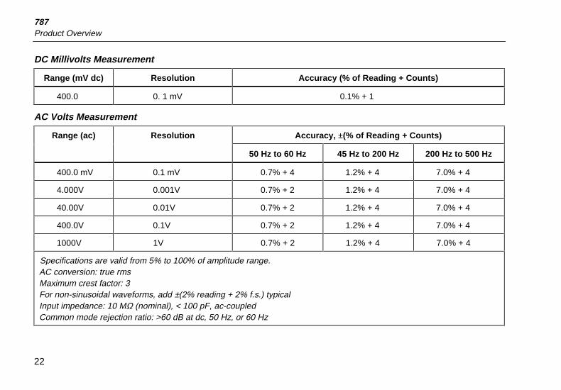
DC Millivolts Measurement
Range (mV dc) Resolution Accuracy (% of Reading + Counts)
400.0 0. 1 mV 0.1% + 1
AC Volts Measurement
Range (ac) Resolution Accuracy, ±(% of Reading + Counts)
50 Hz to 60 Hz 45 Hz to 200 Hz 200 Hz to 500 Hz
400.0 mV 0.1 mV 0.7% + 4 1.2% + 4 7.0% + 4
4.000V 0.001V 0.7% + 2 1.2% + 4 7.0% + 4
40.00V 0.01V 0.7% + 2 1.2% + 4 7.0% + 4
400.0V 0.1V 0.7% + 2 1.2% + 4 7.0% + 4
1000V 1V 0.7% + 2 1.2% + 4 7.0% + 4
Specifications are valid from 5% to 100% of amplitude range.AC conversion: true rmsMaximum crest factor: 3For non-sinusoidal waveforms, add ±(2% reading + 2% f.s.) typicalInput impedance: 10 MΩ (nominal), < 100 pF, ac-coupledCommon mode rejection ratio: >60 dB at dc, 50 Hz, or 60 Hz
ProcessMeterSpecifications
23
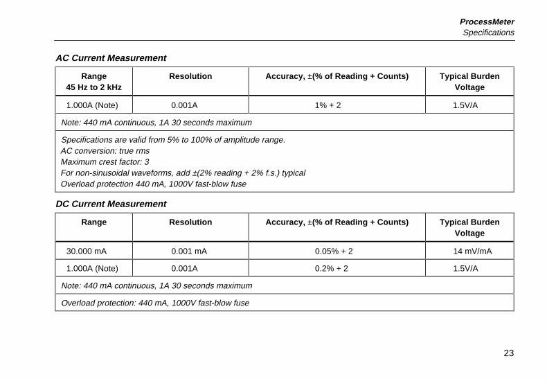
AC Current Measurement
Range45 Hz to 2 kHz
Resolution Accuracy, ±(% of Reading + Counts) Typical BurdenVoltage
1.000A (Note) 0.001A 1% + 2 1.5V/A
Note: 440 mA continuous, 1A 30 seconds maximum
Specifications are valid from 5% to 100% of amplitude range.AC conversion: true rmsMaximum crest factor: 3For non-sinusoidal waveforms, add ±(2% reading + 2% f.s.) typicalOverload protection 440 mA, 1000V fast-blow fuse
DC Current Measurement
Range Resolution Accuracy, ±(% of Reading + Counts) Typical BurdenVoltage
30.000 mA 0.001 mA 0.05% + 2 14 mV/mA
1.000A (Note) 0.001A 0.2% + 2 1.5V/A
Note: 440 mA continuous, 1A 30 seconds maximum
Overload protection: 440 mA, 1000V fast-blow fuse
787Product Overview
24
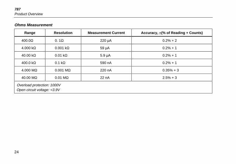
Ohms Measurement
Range Resolution Measurement Current Accuracy, ±(% of Reading + Counts)
400.0Ω 0. 1Ω 220 µA 0.2% + 2
4.000 kΩ 0.001 kΩ 59 µA 0.2% + 1
40.00 kΩ 0.01 kΩ 5.9 µA 0.2% + 1
400.0 kΩ 0.1 kΩ 590 nA 0.2% + 1
4.000 MΩ 0.001 MΩ 220 nA 0.35% + 3
40.00 MΩ 0.01 MΩ 22 nA 2.5% + 3
Overload protection: 1000VOpen circuit voltage: <3.9V
ProcessMeterSpecifications
25
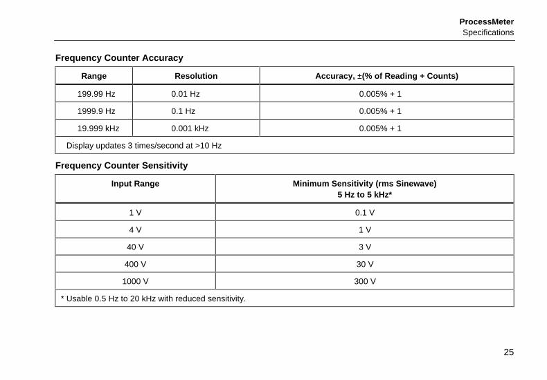
Frequency Counter Accuracy
Range Resolution Accuracy, ±(% of Reading + Counts)
199.99 Hz 0.01 Hz 0.005% + 1
1999.9 Hz 0.1 Hz 0.005% + 1
19.999 kHz 0.001 kHz 0.005% + 1
Display updates 3 times/second at >10 Hz
Frequency Counter Sensitivity
Input Range Minimum Sensitivity (rms Sinewave)5 Hz to 5 kHz*
1 V 0.1 V
4 V 1 V
40 V 3 V
400 V 30 V
1000 V 300 V
* Usable 0.5 Hz to 20 kHz with reduced sensitivity.
787Product Overview
26
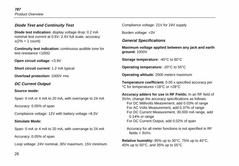
Diode Test and Continuity Test
Diode test indication: display voltage drop: 0.2 mAnominal test current at 0.6V: 2.4V full scale, accuracy±(2% + 1 count)
Continuity test indication: continuous audible tone fortest resistance <100Ω
Open circuit voltage: <3.9V
Short circuit current: 1.2 mA typical
Overload protection: 1000V rms
DC Current Output
Source mode:
Span: 0 mA or 4 mA to 20 mA, with overrange to 24 mA
Accuracy: 0.05% of span
Compliance voltage: 12V with battery voltage >8.5V
Simulate Mode:
Span: 0 mA or 4 mA to 20 mA, with overrange to 24 mA
Accuracy: 0.05% of span
Loop voltage: 24V nominal, 30V maximum, 15V minimum
Compliance voltage: 21V for 24V supply
Burden voltage: <3V
General Specifications
Maximum voltage applied between any jack and earthground: 1000V
Storage temperature: -40°C to 60°C
Operating temperature: -20°C to 55°C
Operating altitude: 2000 meters maximum
Temperature coefficient: 0.05 x specified accuracy per°C for temperatures <18°C or >28°C
Accuracy adders for use in RF Fields: In an RF field of3V/m, change the accuracy specifications as follows:
For DC Millivolts Measrement, add 0.03% of rangeFor AC Volts Measurement, add 0.37% of rangeFor DC Current Measurement, 30.000 mA range, add
0.14% or rangeFor DC Current Output, add 0.02% of span
Accuracy for all meter functions is not specified in RF fields > 3V/m.
Relative humidity: 95% up to 30°C, 75% up to 40°C,45% up to 50°C, and 35% up to 55°C
ProcessMeterSpecifications
27
Vibration: Random 2g, 5 to 500 Hz
Shock: 1 meter drop test
Water and dust protection: Complies with IEC529 IP52(normal operating vacuum used for dust test)
Safety: Complies with IEC1010-1, ANSI/ISA S82.01-1994 and CAN/CSA C22.2 No. 1010.1-92 OvervoltageCategory III.
Power requirements: Single 9V battery (ANSI/NEDA1604A or IEC 6LR61)
Size: 32 mm H x 87 mm W x 187 mm L (1.25 in H x 3.41in W x 7.35 in L);
With holster and Flex-Stand: 52 mm H x 98 mm W x 201mm L (2.06 in H x 3.86 in W x 7.93 in L)
Weight: 369 g (13 oz);
With holster and Flex-Stand: 638 g (22.5 oz)
Certifications: CSA, UL, TÜV

787Product Overview
28