Embed Size (px)
Citation preview
Trouble Shooting Guide1. Keyed switch is in the on position.2. On front of alarm the alarm/off switch is in alarm position. See
picture on front cover. 3. Dip switches on the side for alarm are set as follows: 1 is in the
(down) position and 2, 3, and 4 are in up position. See pages 6 inthe alarm activation section of manual.
4. Check key and door switch connections are pushed in and secure.See page 5, figure 2.
5. Check connection on strobe (if so fitted) that it is pushed in andsecure. See page 9, figure 9
At this point the alarm should sound when door is opened and shut off when door is closed.
If the alarm sounds as soon as the keyed switch is turned to the (on) position with the door closed, check the following:
1. Dip switches on the side for alarm are set as follows: 1 is in the(down) position and 2, 3, and 4 are in up position. See pages 6-7in the alarm activation section of manual.
2. There is a rubber bumper the door switch makes contact withwhen door is closed. Check to see that the rubber bumper is inposition to make contact with the door switch.
If the alarm does not sound when door is opened. Check items 1-5 in the above list and also try a new battery.
If these instructions do not get the alarm operating, please contact your distributor.
AED CabinetAnd
Alarm Manual
MMP MODEL 200900 ALARM SYSTEM
Table of ContentsAssembly and Installation………………..………………………..… 2-3
o Door handle and roller latch assemblyo Surface Mount installationo Recessed and Semi-recessed installation
Alarm (optional, can be added later)……………………………….… 4 o Features
Alarm volume Alarm settings External alarm relay wiring Low battery chirp
Alarm Switches.…………………………………………………..….. 5 o Key Switcho Door switch
Alarm Activation Settings..…………………………………….….… 5-6
Alarm External Contacts….………………………………………… 7
Battery…………………..…………………………………………… 7-8 o Installationo Full operationo Maintenance
Strobe Light Option …………………………………………..…..… 9
Cabinet Specifications …………….………………..………………. 10
Trouble Shooting Guide ……………..……………………………... 11
-1-
Cabinet Specifications
RO
UG
H W
ALL
OPE
NIN
G
Dep
th
2"
4.25
"
4"
6.25
"
4"
6.25
"
4"
6.25
"
Wid
th
12.5
"
12.5
"
12.5
"
12.5
"
15"
15"
13"
13"
Hei
ght
12"
12"
12"
12"
15"
15"
28"
28"
OU
TSID
E D
IMEN
SIO
NS
Dep
th
5"
3.12
5"
1"
7"
3.12
5"
1"
7"
3.12
5"
1"
9"
8.5"
2.5"
1"
9.5"
Wid
th
13.5
"
13.5
"
13.5
"
13.5
"
13.5
"
13.5
"
17.5
"
17.5
"
17.5
"
17.5
"
15.5
"
15.5
"
15.5
"
15.5
"
Hei
ght
13"
13"
13"
13"
13"
13"
17.5
"
17.5
"
17.5
"
17.5
"
30.5
"
30.5
"
30.5
"
37.7
5"
INSI
DE
DIM
ENSI
ON
S
Dep
th
4.87
5"
4.87
5"
4.87
5"
6.87
5"
6.87
5"
6.87
5"
6.87
5"
6.87
5"
6.87
5"
8.87
5"
8.37
5"
6.37
5"
6.37
5"
9.37
5"
Wid
th
13.3
75"
11.3
75
11.3
75
13.3
75"
11.3
75
11.3
75
17.3
75"
14.1
25"
14.1
25"
17.3
75"
15.3
75"
11.8
75
11.8
75
15.3
75"
Hei
ght
12.8
75"
10.8
75"
10.8
75"
12.8
75"
10.8
75"
10.8
75"
17.3
75"
14.1
25"
14.1
25"
17.3
75"
30.3
75"
26.8
75"
26.8
75"
37.6
25
MO
UN
T
SM
SR
3
R1
SM
SR
3
R1
SM
SR
3
R1
SM
SM
SR
3
R1
SM
SIZ
E
145
147
180
189
184
186
-10-

Strobe Light OptionStrobe
A built in strobe light on your cabinet provides two key benefits:1. It is an excellent visual indicator of an emergency or
as a deterrent to tampering.2. In loud environments it provides a highly visible alert
where the audible alarm could go unnoticed.
If you purchased a strobe light with your cabinet it is installed prior to shipping and is connected to the alarm.
Strobe option is available for surface mount, recessed and semi-recessed cabinets.
Adding a strobeYou may purchase a strobe light separately at any timefor use with cabinets equipped with an alarm.
Figure 9
-9 -
Assembly and InstallationDoor handle and roller latch assembly
1. Locate plastic bag containing: cabinet door handle, roller latch,and mounting screws.
2. Secure the handle opposite the hinge on the cabinet door. Usethe ¾” machine screws to mount the handle. See figure 1
3. Fasten the roller latch on the inside of the cabinet door. Place theroller over the two oval holes found between the handle screwsso it faces away from the window. Secure the roller latch usingtwo 3/8” sheet metal screws provided. The oval holes enableyou to slide the roller latch right (to door edge) to increase or leftto decrease door tension.
Figure 1
- 2 -
Strobe Mount door handle with 3/4” screws
Mount roller latch with 3/8” screws

Assembly and InstallationSurface mount installation
1. Locate metal or wood studs within the walls and mark theirlocations.
2. Four mounting holes are on the back of the cabinet. Werecommend that you fasten a minimum of two of these anchorpoints into one or more wall studs.
Surface Mount
Recessed and Semi-recessed mount installation 1. In a wall constructed of metal or wood studs. Install a framed
opening in the wall at the cabinet’s intended location. Wallopening width, height, and depth must correspond to the tankdimensions of the cabinet.
2. Cabinet measurements featured on page 10.3. Frame wall above, below and on both sides of cabinet opening.
Place cabinet in position and anchor cabinet using the holes inthe cabinet’s side. Attach cabinet to intended location usingscrews, bolts or anchors as required (Not supplied).
Semi-recessed
-3 -
BatteryFull operation
When the unit is activated and the strobe and buzzer are functioning, the unit will function for a full two hours. Note: The battery should be changed every time the unit is activated to ensure full life expectance.
MaintenanceOnly use a new, 9-volt alkaline battery. A new battery may last approximately two years while in “standby” mode, semi-annual battery change is recommended. The alarm will emit a “chirp” sound when the battery level has reached its lowest level.
Figure 8
-8 -
Remove Screw

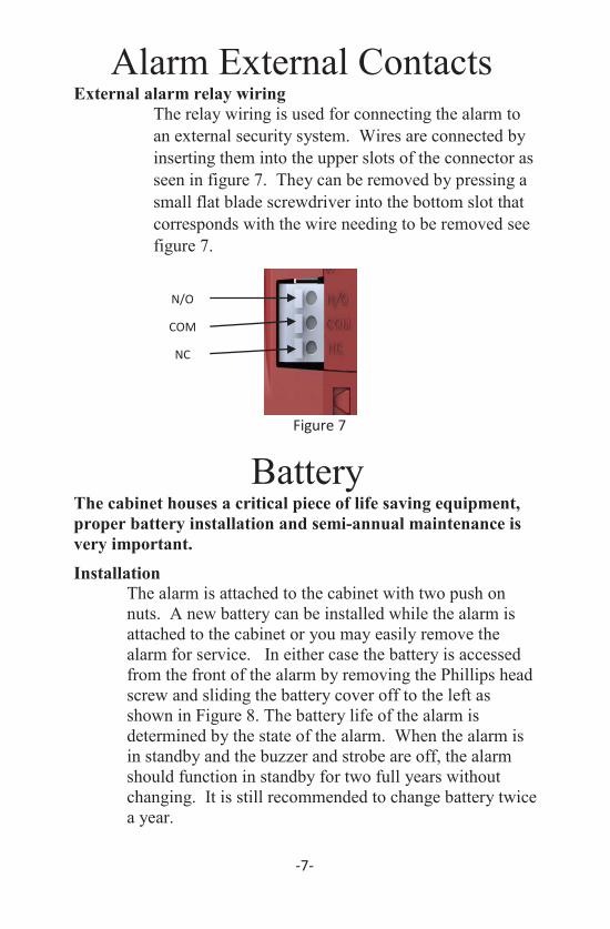
Alarm External ContactsExternal alarm relay wiring
The relay wiring is used for connecting the alarm to an external security system. Wires are connected by inserting them into the upper slots of the connector as seen in figure 7. They can be removed by pressing a small flat blade screwdriver into the bottom slot that corresponds with the wire needing to be removed see figure 7.
Figure 7
BatteryThe cabinet houses a critical piece of life saving equipment, proper battery installation and semi-annual maintenance is very important. Installation
The alarm is attached to the cabinet with two push on nuts. A new battery can be installed while the alarm is attached to the cabinet or you may easily remove the alarm for service. In either case the battery is accessed from the front of the alarm by removing the Phillips head screw and sliding the battery cover off to the left as shown in Figure 8. The battery life of the alarm is determined by the state of the alarm. When the alarm is in standby and the buzzer and strobe are off, the alarm should function in standby for two full years without changing. It is still recommended to change battery twice a year.
-7-
AlarmAlarm volume
The alarm has a very high decibel level (85-120 db). The decibel level will vary with the life of the battery. See pages 7 and 8 for more information on battery life.
Alarm settingsAlarm has the option to be activated in four different settings. See pages 5 and 6 for more information on activation settings.
1. Alarm activated when door is opened, shuts off whendoor is closed.
2. Alarm activated when door is opened, shuts off withkey only.
3. Activates for 30 seconds, when door is opened.4. Activates for 3 minutes, when door is opened.
External alarm relay wiring The optional relay wiring is used to connect the alarm to an external security monitoring system. See page 7 for more details.
Low battery chirpAlarm has a low battery chirp to warn when battery is low. When chirp is heard change the battery as soon as possible. See the section on batteries for instructions on how to change battery.
-4-
COM
NC
N/O
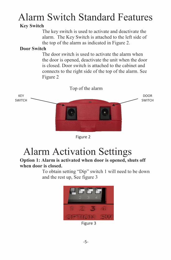
Alarm Switch Standard FeaturesKey Switch
The key switch is used to activate and deactivate the alarm. The Key Switch is attached to the left side of the top of the alarm as indicated in Figure 2.
Door SwitchThe door switch is used to activate the alarm when the door is opened, deactivate the unit when the door is closed. Door switch is attached to the cabinet and connects to the right side of the top of the alarm. See Figure 2
Top of the alarm
Figure 2
Alarm Activation SettingsOption 1: Alarm is activated when door is opened, shuts off when door is closed.
To obtain setting “Dip” switch 1 will need to be down and the rest up, See figure 3
Figure 3
-5-
Alarm Activation SettingsOption 2: Door is “open” alarm is activated until reset or
turned off with the key switchTo obtain setting all of the “DIP” switches are in the up position see in Figure 4
Figure 4
Option 3: Alarm activates for 30 seconds after door is openedTo obtain setting “Dip” switches 1, 2 and 3 are in the down position, switch 4 is in the up position, see Figure 5
Figure 5
Option 4: Alarm activates for 3 minutes after door is openedTo obtain setting “Dip” switches 1, 2, and 4 are in the down position and switch 3 is the up position, see Figure 6
Figure 6
-6-
KEY SWITCH
DOOR SWITCH
Alarm External ContactsExternal alarm relay wiring
The relay wiring is used for connecting the alarm to an external security system. Wires are connected by inserting them into the upper slots of the connector as seen in figure 7. They can be removed by pressing a small flat blade screwdriver into the bottom slot that corresponds with the wire needing to be removed see figure 7.
Figure 7
BatteryThe cabinet houses a critical piece of life saving equipment, proper battery installation and semi-annual maintenance is very important. Installation
The alarm is attached to the cabinet with two push on nuts. A new battery can be installed while the alarm is attached to the cabinet or you may easily remove the alarm for service. In either case the battery is accessed from the front of the alarm by removing the Phillips head screw and sliding the battery cover off to the left as shown in Figure 8. The battery life of the alarm is determined by the state of the alarm. When the alarm is in standby and the buzzer and strobe are off, the alarm should function in standby for two full years without changing. It is still recommended to change battery twice a year.
-7-
AlarmAlarm volume
The alarm has a very high decibel level (85-120 db). The decibel level will vary with the life of the battery. See pages 7 and 8 for more information on battery life.
Alarm settingsAlarm has the option to be activated in four different settings. See pages 5 and 6 for more information on activation settings.
1. Alarm activated when door is opened, shuts off whendoor is closed.
2. Alarm activated when door is opened, shuts off withkey only.
3. Activates for 30 seconds, when door is opened.4. Activates for 3 minutes, when door is opened.
External alarm relay wiring The optional relay wiring is used to connect the alarm to an external security monitoring system. See page 7 for more details.
Low battery chirpAlarm has a low battery chirp to warn when battery is low. When chirp is heard change the battery as soon as possible. See the section on batteries for instructions on how to change battery.
-4-
COM
NC
N/O

Assembly and InstallationSurface mount installation
1. Locate metal or wood studs within the walls and mark theirlocations.
2. Four mounting holes are on the back of the cabinet. Werecommend that you fasten a minimum of two of these anchorpoints into one or more wall studs.
Surface Mount
Recessed and Semi-recessed mount installation 1. In a wall constructed of metal or wood studs. Install a framed
opening in the wall at the cabinet’s intended location. Wallopening width, height, and depth must correspond to the tankdimensions of the cabinet.
2. Cabinet measurements featured on page 10.3. Frame wall above, below and on both sides of cabinet opening.
Place cabinet in position and anchor cabinet using the holes inthe cabinet’s side. Attach cabinet to intended location usingscrews, bolts or anchors as required (Not supplied).
Semi-recessed
-3 -
BatteryFull operation
When the unit is activated and the strobe and buzzer are functioning, the unit will function for a full two hours. Note: The battery should be changed every time the unit is activated to ensure full life expectance.
MaintenanceOnly use a new, 9-volt alkaline battery. A new battery may last approximately two years while in “standby” mode, semi-annual battery change is recommended. The alarm will emit a “chirp” sound when the battery level has reached its lowest level.
Figure 8
-8 -
Remove Screw

Strobe Light OptionStrobe
A built in strobe light on your cabinet provides two key benefits:1. It is an excellent visual indicator of an emergency or
as a deterrent to tampering.2. In loud environments it provides a highly visible alert
where the audible alarm could go unnoticed.
If you purchased a strobe light with your cabinet it is installed prior to shipping and is connected to the alarm.
Strobe option is available for surface mount, recessed and semi-recessed cabinets.
Adding a strobeYou may purchase a strobe light separately at any timefor use with cabinets equipped with an alarm.
Figure 9
-9 -
Assembly and InstallationDoor handle and roller latch assembly
1. Locate plastic bag containing: cabinet door handle, roller latch,and mounting screws.
2. Secure the handle opposite the hinge on the cabinet door. Usethe ¾” machine screws to mount the handle. See figure 1
3. Fasten the roller latch on the inside of the cabinet door. Place theroller over the two oval holes found between the handle screwsso it faces away from the window. Secure the roller latch usingtwo 3/8” sheet metal screws provided. The oval holes enableyou to slide the roller latch right (to door edge) to increase or leftto decrease door tension.
Figure 1
- 2 -
Strobe Mount door handle with 3/4” screws
Mount roller latch with 3/8” screws

Table of ContentsAssembly and Installation………………..………………………..… 2-3
o Door handle and roller latch assemblyo Surface Mount installationo Recessed and Semi-recessed installation
Alarm (optional, can be added later)……………………………….… 4 o Features
Alarm volume Alarm settings External alarm relay wiring Low battery chirp
Alarm Switches.…………………………………………………..….. 5 o Key Switcho Door switch
Alarm Activation Settings..…………………………………….….… 5-6
Alarm External Contacts….………………………………………… 7
Battery…………………..…………………………………………… 7-8 o Installationo Full operationo Maintenance
Strobe Light Option …………………………………………..…..… 9
Cabinet Specifications …………….………………..………………. 10
Trouble Shooting Guide ……………..……………………………... 11
-1-
Cabinet Specifications R
OU
GH
WA
LL O
PEN
ING
Dep
th
2"
4.25
"
4"
6.25
"
4"
6.25
"
4"
6.25
"
Wid
th
12.5
"
12.5
"
12.5
"
12.5
"
15"
15"
13"
13"
Hei
ght
12"
12"
12"
12"
15"
15"
28"
28"
OU
TSID
E D
IMEN
SIO
NS
Dep
th
5"
3.12
5"
1"
7"
3.12
5"
1"
7"
3.12
5"
1"
9"
8.5"
2.5"
1"
9.5"
Wid
th
13.5
"
13.5
"
13.5
"
13.5
"
13.5
"
13.5
"
17.5
"
17.5
"
17.5
"
17.5
"
15.5
"
15.5
"
15.5
"
15.5
"
Hei
ght
13"
13"
13"
13"
13"
13"
17.5
"
17.5
"
17.5
"
17.5
"
30.5
"
30.5
"
30.5
"
37.7
5"
INSI
DE
DIM
ENSI
ON
S
Dep
th
4.87
5"
4.87
5"
4.87
5"
6.87
5"
6.87
5"
6.87
5"
6.87
5"
6.87
5"
6.87
5"
8.87
5"
8.37
5"
6.37
5"
6.37
5"
9.37
5"
Wid
th
13.3
75"
11.3
75
11.3
75
13.3
75"
11.3
75
11.3
75
17.3
75"
14.1
25"
14.1
25"
17.3
75"
15.3
75"
11.8
75
11.8
75
15.3
75"
Hei
ght
12.8
75"
10.8
75"
10.8
75"
12.8
75"
10.8
75"
10.8
75"
17.3
75"
14.1
25"
14.1
25"
17.3
75"
30.3
75"
26.8
75"
26.8
75"
37.6
25
MO
UN
T
SM
SR
3
R1
SM
SR
3
R1
SM
SR
3
R1
SM
SM
SR
3
R1
SM
SIZ
E
145
147
180
189
184
186
-10-
Trouble Shooting Guide1. Keyed switch is in the on position.2. On front of alarm the alarm/off switch is in alarm position. See
picture on front cover. 3. Dip switches on the side for alarm are set as follows: 1 is in the
(down) position and 2, 3, and 4 are in up position. See pages 6 inthe alarm activation section of manual.
4. Check key and door switch connections are pushed in and secure.See page 5, figure 2.
5. Check connection on strobe (if so fitted) that it is pushed in andsecure. See page 9, figure 9
At this point the alarm should sound when door is opened and shut off when door is closed.
If the alarm sounds as soon as the keyed switch is turned to the (on) position with the door closed, check the following:
1. Dip switches on the side for alarm are set as follows: 1 is in the(down) position and 2, 3, and 4 are in up position. See pages 6-7in the alarm activation section of manual.
2. There is a rubber bumper the door switch makes contact withwhen door is closed. Check to see that the rubber bumper is inposition to make contact with the door switch.
If the alarm does not sound when door is opened. Check items 1-5 in the above list and also try a new battery.
If these instructions do not get the alarm operating, please contact your distributor.
AED CabinetAnd
Alarm Manual
MMP MODEL 200900 ALARM SYSTEM