Embed Size (px)
Citation preview
1412
7.7 Regulators— Pressure
R. L. MOORE (1970) D. M. HANLON (1985)
B. G. LIPTÁK (1995) J.E. JAMISON (2005)
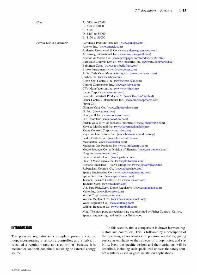
Regulator Types: A. Weight-loadedB. Spring-loadedC. Piloted 1/4 in. (6.25 mm) air regulatorD. Internally pilotedE. Externally piloted
Sizes: A. 1/2 to 6 in. (12.5 to 150 mm)B. 1/4 to 4 in. (6.25 to 100 mm)C. 1/4 in. (6.25 mm)D. 1/2 to 6 in. (12.5 to 150 mm)E. 3/4 to 12 in. (9.35 to 300 mm)
Design Inlet Pressure: B. Up to 6000 PSIG (41.4 MPa)D and E. Up to 1500 PSIG (10.35 MPa)A and C. Up to 500 PSIG (3.45 MPa)
Minimum Regulated Outlet B and E. Down to 2 PSIG (13.8 kPa)Pressure: A and D. Down to 0.5 PSIG (3.45 kPa)
C. Down to 0.1 PSIG (0.69 kPa)
Droop or Offset: B. 5 to 80% E. 2 to 10% A and D. 1 to 2% C. 0.5%
Regulator Specification Form: See Table 7.7r at the end of this section
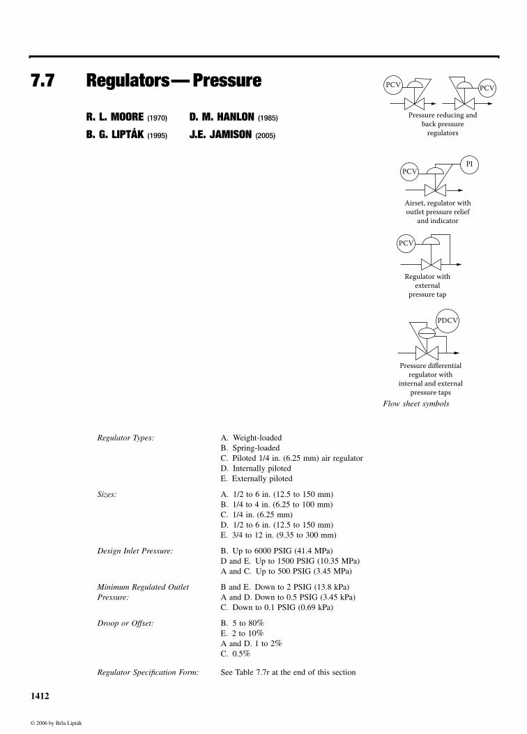
PCV PCV
Pressure reducing andback pressure
regulators
PCV
PCV
PI
Airset, regulator withoutlet pressure relief
and indicator
Regulator withexternal
pressure tap
PDCV
Pressure differentialregulator with
internal and externalpressure taps
Flow sheet symbols
© 2006 by Béla Lipták
7.7 Regulators— Pressure 1413
Cost: A. $150 to $2000B. $50 to $1000C. $100D. $150 to $4000E. $150 to $6000
Partial List of Suppliers: Advanced Pressure Products (www.pmiapp.com)Ametek Inc. (www.ametek.com)Anderson Greenwood & Co. (www.andersongreenwood.com)Armstrong International Inc. (www.armstrong-intl.com)Atwood & Morrill Co. (www.petropages.com/vendors/v7566.htm)Barksdale Controls Div. of IMO Industries Inc. (www.flw.com/barksdale)Bellofram Corp. (www.marshbellofram.com)Brooks Instrument (www.fischerporter.com)A. W. Cash Valve Manufacturing Co. (www.cashacme.com)Cashco Inc. (www.cashco.com)Circle Seal Controls Inc. (www.circle-seal.com)Control Components Inc. (www.ccivalve.com)CPV Manufacturing Inc. (www.cpvmfg.com)Eaton Corp. (www.aeroquip.com)Fairchild Industrial Products Co. (www.flw.com/fairchild)Fisher Controls International Inc. (www.emersonprocess.com)Furon Co. Gilmore Valve Co. (www.gilmorevalve.com)Go Inc. (www.goreg.com)Honeywell Inc. (www.honeywell.com)ITT Conoflow (www.conoflow.com)Jordan Valve (Div. of Richards Industries) (www.jordanvalve.com)Kaye & MacDonald Inc. (www.kayemacdonald.com)Keane Controls Corp. (www.tyco.com)Keystone International Inc. (www.business.com/directory/)Leslie Controls Inc. (www.lesliecontrols.com)Masoneilan (www.masoneilan.com)Matheson Gas Products Inc. (www.thinkenergy.com)Moore Products Co., a Division of Siemens (www.sea.siemens.com)Norgren (www.norgren.com)Parker Hannifin Corp. (www.parker.com)Plast-O-Matic Valves Inc. (www.plastomatic.com)Richards Industries —Valve Group Inc. (www.jordanvalve.com)Robertshaw Controls Co. (www.robertshaw.com)Spence Engineering Co. (www.spenceengineering.com)Spirax Sarco Inc. (www.spirexsarco.com)Tescom, Pressure Controls Div. (www.tescom.com)Tokheim Corp. (www.tokheim.com)U.S. Para Plate/Servo-Dome Regulators (www.usparaplate.com)Valtek Inc. (www.flowserve.com)Veriflo Corp. (www.parker.com)Watson McDaniel Co. (www.watsonmcdaniel.com)Watts Regulator Co. (www.wattsreg.com)Wilkins Regulator Co. (www.trumbull.com)
Note: The most popular regulators are manufactured by Fisher Controls, Cashco,Spence Engineering, and Anderson Greenwood.
INTRODUCTION
The pressure regulator is a complete pressure controlloop, incorporating a sensor, a controller, and a valve. Itis called a regulator (and not a controller) because it ismechanical and self-contained, requiring no external energysource.
In this section, first a comparison is drawn between reg-ulators and controllers. This is followed by a description ofthe operating characteristics of pressure regulators, givingparticular emphasis to the subjects of droop, noise, and sta-bility. Next, the specific designs and their variations will bedescribed, including such specialized units as the safety shut-off regulators used in gasoline station applications.
© 2006 by Béla Lipták
1414 Regulators and Final Control Elements
REGULATORS VS. CONTROL VALVES
In many applications, pressure can be controlled by either aregulator or a full control loop. In making the choice, thedesign engineer should consider their relative merits, whichare listed in Table 7.7a.
Particularly in the smaller sizes, regulators usually costless than a control loop consisting of a control valve, trans-mitter, and controller. Regulators are less expensive to buy,install, and maintain. But when the application requires alarger valve, the economics begin to change and, in sizes over4–6 in. (100–150 mm), might favor of control valves.
Regulators have a built-in controller and do not requirean air supply. This results in savings in both purchase andinstallation costs. As a consequence, regulators are not sub-ject to air-supply failure. In applications where the fail-safefeature is essential or in locations that are remote from asource of compressed air, this is an important consideration.On the other hand, diaphragm failure in a regulator usuallyresults in the opening of the valve, which can be unsafe.
Control Valves
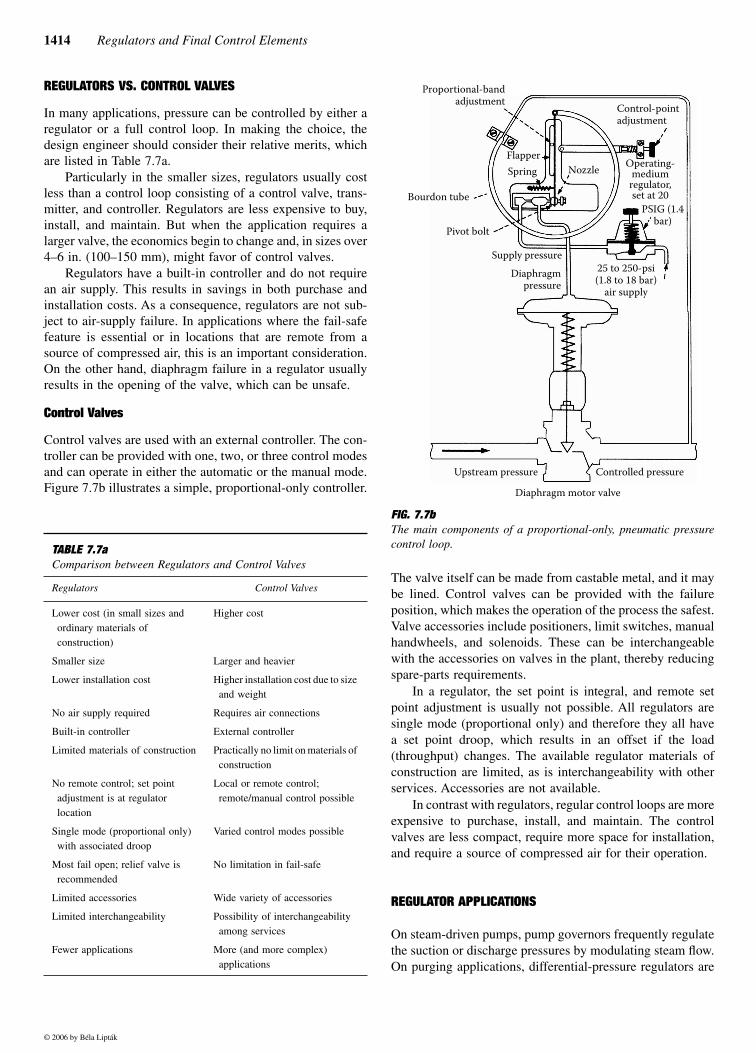
Control valves are used with an external controller. The con-troller can be provided with one, two, or three control modesand can operate in either the automatic or the manual mode.Figure 7.7b illustrates a simple, proportional-only controller.
The valve itself can be made from castable metal, and it maybe lined. Control valves can be provided with the failureposition, which makes the operation of the process the safest.Valve accessories include positioners, limit switches, manualhandwheels, and solenoids. These can be interchangeablewith the accessories on valves in the plant, thereby reducingspare-parts requirements.
In a regulator, the set point is integral, and remote setpoint adjustment is usually not possible. All regulators aresingle mode (proportional only) and therefore they all havea set point droop, which results in an offset if the load(throughput) changes. The available regulator materials ofconstruction are limited, as is interchangeability with otherservices. Accessories are not available.
In contrast with regulators, regular control loops are moreexpensive to purchase, install, and maintain. The controlvalves are less compact, require more space for installation,and require a source of compressed air for their operation.
REGULATOR APPLICATIONS
On steam-driven pumps, pump governors frequently regulatethe suction or discharge pressures by modulating steam flow.On purging applications, differential-pressure regulators are
TABLE 7.7a Comparison between Regulators and Control Valves
Regulators Control Valves
Lower cost (in small sizes and ordinary materials of construction)
Higher cost
Smaller size Larger and heavier
Lower installation cost Higher installation cost due to size and weight
No air supply required Requires air connections
Built-in controller External controller
Limited materials of construction Practically no limit on materials of construction
No remote control; set point adjustment is at regulator location
Local or remote control; remote/manual control possible
Single mode (proportional only) with associated droop
Varied control modes possible
Most fail open; relief valve is recommended
No limitation in fail-safe
Limited accessories Wide variety of accessories
Limited interchangeability Possibility of interchangeability among services
Fewer applications More (and more complex) applications
FIG. 7.7b The main components of a proportional-only, pneumatic pressurecontrol loop.
Proportional-bandadjustment Control-point
adjustment
Bourdon tube
FlapperNozzle
Pivot bolt
Spring
Supply pressureDiaphragm
pressure25 to 250-psi(1.8 to 18 bar)
air supply
Operating-medium
regulator,set at 20
Upstream pressure
Diaphragm motor valve
Controlled pressure
PSIG (1.4bar)
© 2006 by Béla Lipták
7.7 Regulators— Pressure 1415
used to keep the purging media at a pressure higher than thatof the process. This same regulator is also used in air bubbler-type level measurement systems. A differential-pressure reduc-ing valve can also be used to provide constant water flow forwet-bulb humidity detection.
Oil-burner back-pressure regulators are installed in theoil return line. Their settings are modified according to thesteam pressure in the boiler. The regulator stem is discontin-uous to permit both low- and high-fire pressure adjustments.
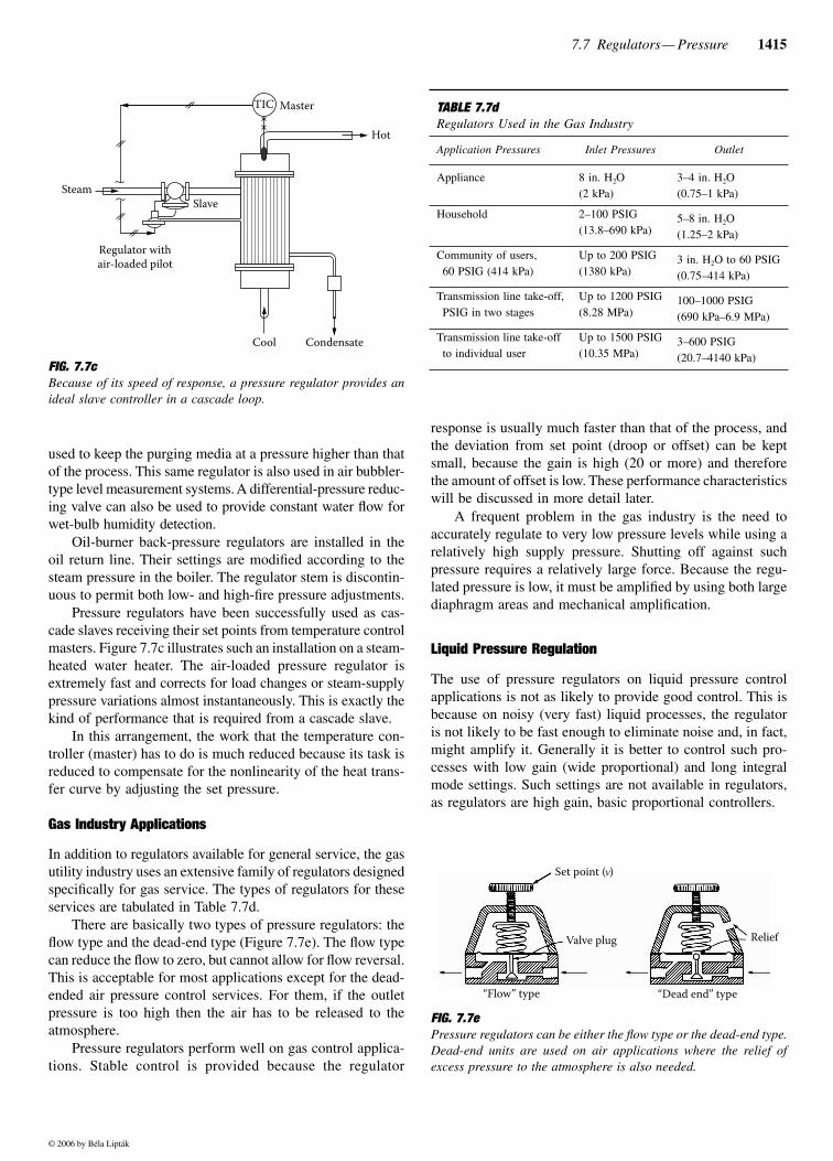
Pressure regulators have been successfully used as cas-cade slaves receiving their set points from temperature controlmasters. Figure 7.7c illustrates such an installation on a steam-heated water heater. The air-loaded pressure regulator isextremely fast and corrects for load changes or steam-supplypressure variations almost instantaneously. This is exactly thekind of performance that is required from a cascade slave.
In this arrangement, the work that the temperature con-troller (master) has to do is much reduced because its task isreduced to compensate for the nonlinearity of the heat trans-fer curve by adjusting the set pressure.
Gas Industry Applications
In addition to regulators available for general service, the gasutility industry uses an extensive family of regulators designedspecifically for gas service. The types of regulators for theseservices are tabulated in Table 7.7d.
There are basically two types of pressure regulators: theflow type and the dead-end type (Figure 7.7e). The flow typecan reduce the flow to zero, but cannot allow for flow reversal.This is acceptable for most applications except for the dead-ended air pressure control services. For them, if the outletpressure is too high then the air has to be released to theatmosphere.
Pressure regulators perform well on gas control applica-tions. Stable control is provided because the regulator
response is usually much faster than that of the process, andthe deviation from set point (droop or offset) can be keptsmall, because the gain is high (20 or more) and thereforethe amount of offset is low. These performance characteristicswill be discussed in more detail later.
A frequent problem in the gas industry is the need toaccurately regulate to very low pressure levels while using arelatively high supply pressure. Shutting off against suchpressure requires a relatively large force. Because the regu-lated pressure is low, it must be amplified by using both largediaphragm areas and mechanical amplification.
Liquid Pressure Regulation
The use of pressure regulators on liquid pressure controlapplications is not as likely to provide good control. This isbecause on noisy (very fast) liquid processes, the regulatoris not likely to be fast enough to eliminate noise and, in fact,might amplify it. Generally it is better to control such pro-cesses with low gain (wide proportional) and long integralmode settings. Such settings are not available in regulators,as regulators are high gain, basic proportional controllers.
FIG. 7.7cBecause of its speed of response, a pressure regulator provides anideal slave controller in a cascade loop.
TIC Master
SteamSlave
Cool Condensate
Regulator withair-loaded pilot
Hot
TABLE 7.7dRegulators Used in the Gas Industry
Application Pressures Inlet Pressures Outlet
Appliance 8 in. H2O(2 kPa)
3–4 in. H2O(0.75–1 kPa)
Household 2–100 PSIG(13.8–690 kPa)
5–8 in. H2O(1.25–2 kPa)
Community of users,60 PSIG (414 kPa)
Up to 200 PSIG(1380 kPa)
3 in. H2O to 60 PSIG(0.75–414 kPa)
Transmission line take-off,PSIG in two stages
Up to 1200 PSIG(8.28 MPa)
100–1000 PSIG(690 kPa–6.9 MPa)
Transmission line take-off to individual user
Up to 1500 PSIG(10.35 MPa)
3–600 PSIG(20.7–4140 kPa)
FIG. 7.7ePressure regulators can be either the flow type or the dead-end type.Dead-end units are used on air applications where the relief ofexcess pressure to the atmosphere is also needed.
Valve plug Relief
“Dead end” type
Set point ( )
“Flow” type
© 2006 by Béla Lipták
1416 Regulators and Final Control Elements
Another reason why the use of regulators is usually nota good choice for liquid pressure control is that regulatorsdo not provide tight shut-off. Therefore overpressuring of thesystem due to leakage can occur when the supply regulatoris not fully closed, while there is no demand for the controlledfluid.
Gas Station Safety Regulators
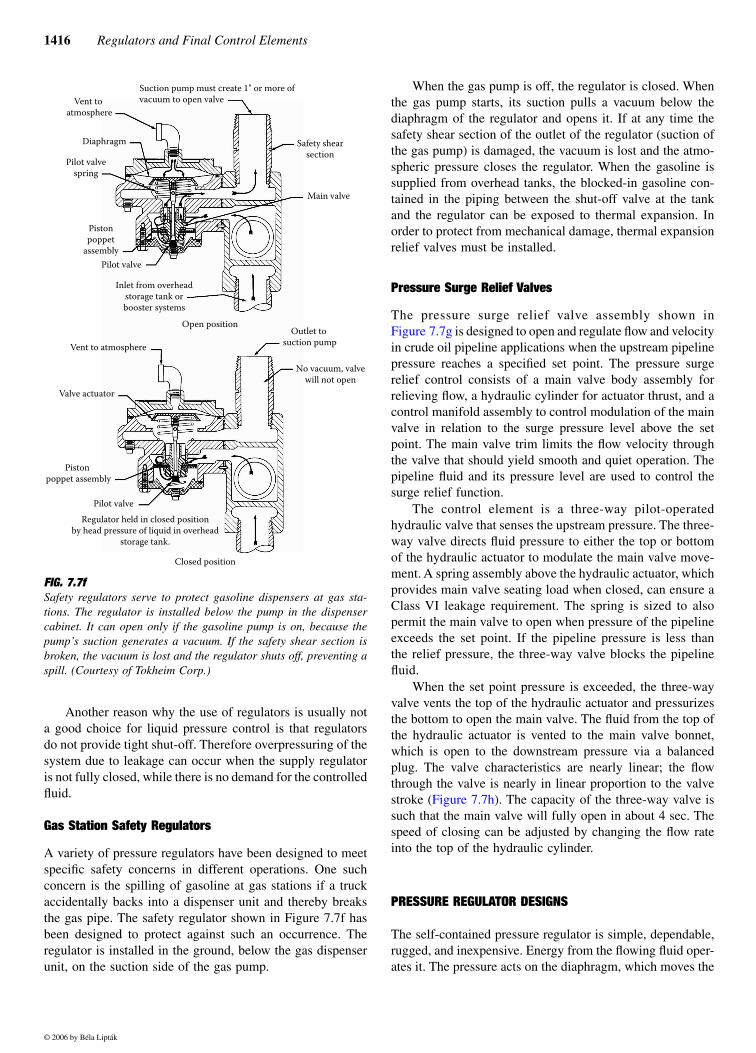
A variety of pressure regulators have been designed to meetspecific safety concerns in different operations. One suchconcern is the spilling of gasoline at gas stations if a truckaccidentally backs into a dispenser unit and thereby breaksthe gas pipe. The safety regulator shown in Figure 7.7f hasbeen designed to protect against such an occurrence. Theregulator is installed in the ground, below the gas dispenserunit, on the suction side of the gas pump.
When the gas pump is off, the regulator is closed. Whenthe gas pump starts, its suction pulls a vacuum below thediaphragm of the regulator and opens it. If at any time thesafety shear section of the outlet of the regulator (suction ofthe gas pump) is damaged, the vacuum is lost and the atmo-spheric pressure closes the regulator. When the gasoline issupplied from overhead tanks, the blocked-in gasoline con-tained in the piping between the shut-off valve at the tankand the regulator can be exposed to thermal expansion. Inorder to protect from mechanical damage, thermal expansionrelief valves must be installed.
Pressure Surge Relief Valves
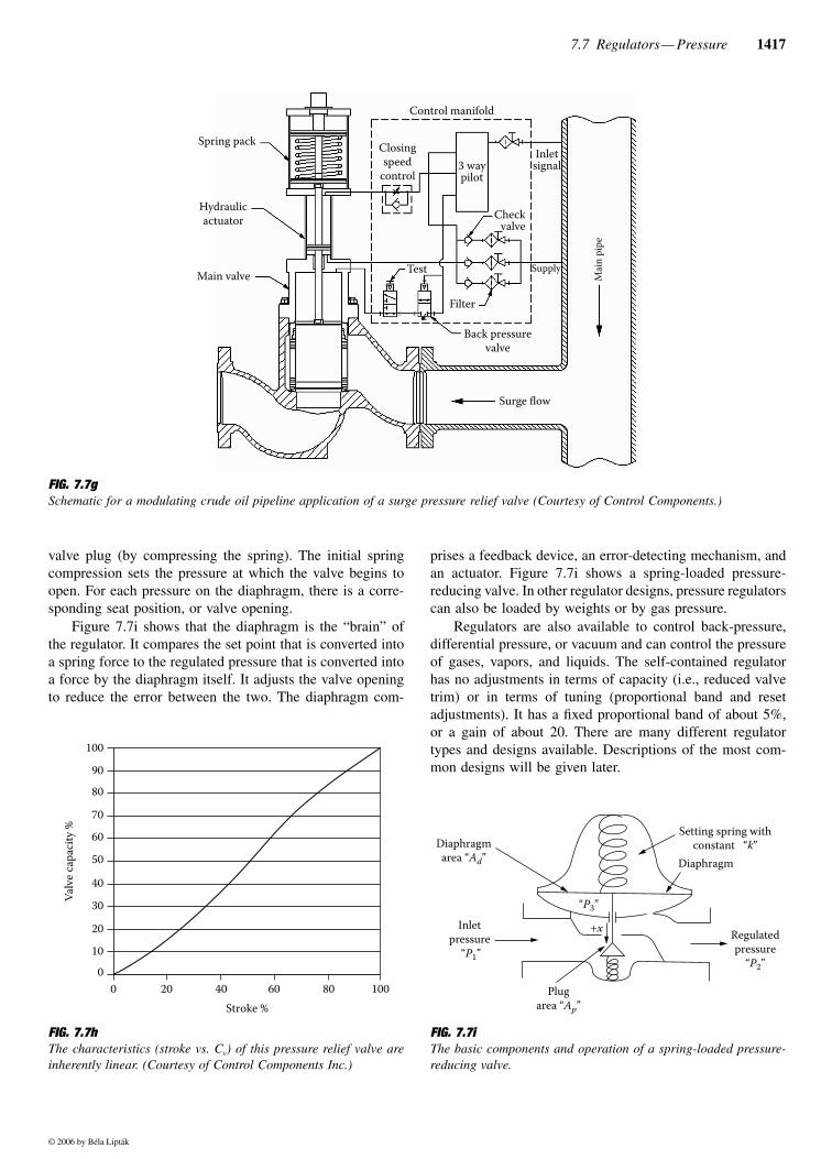
The pressure surge relief valve assembly shown inFigure 7.7g is designed to open and regulate flow and velocityin crude oil pipeline applications when the upstream pipelinepressure reaches a specified set point. The pressure surgerelief control consists of a main valve body assembly forrelieving flow, a hydraulic cylinder for actuator thrust, and acontrol manifold assembly to control modulation of the mainvalve in relation to the surge pressure level above the setpoint. The main valve trim limits the flow velocity throughthe valve that should yield smooth and quiet operation. Thepipeline fluid and its pressure level are used to control thesurge relief function.
The control element is a three-way pilot-operatedhydraulic valve that senses the upstream pressure. The three-way valve directs fluid pressure to either the top or bottomof the hydraulic actuator to modulate the main valve move-ment. A spring assembly above the hydraulic actuator, whichprovides main valve seating load when closed, can ensure aClass VI leakage requirement. The spring is sized to alsopermit the main valve to open when pressure of the pipelineexceeds the set point. If the pipeline pressure is less thanthe relief pressure, the three-way valve blocks the pipelinefluid.
When the set point pressure is exceeded, the three-wayvalve vents the top of the hydraulic actuator and pressurizesthe bottom to open the main valve. The fluid from the top ofthe hydraulic actuator is vented to the main valve bonnet,which is open to the downstream pressure via a balancedplug. The valve characteristics are nearly linear; the flowthrough the valve is nearly in linear proportion to the valvestroke (Figure 7.7h). The capacity of the three-way valve issuch that the main valve will fully open in about 4 sec. Thespeed of closing can be adjusted by changing the flow rateinto the top of the hydraulic cylinder.
PRESSURE REGULATOR DESIGNS
The self-contained pressure regulator is simple, dependable,rugged, and inexpensive. Energy from the flowing fluid oper-ates it. The pressure acts on the diaphragm, which moves the
FIG. 7.7fSafety regulators serve to protect gasoline dispensers at gas sta-tions. The regulator is installed below the pump in the dispensercabinet. It can open only if the gasoline pump is on, because thepump’s suction generates a vacuum. If the safety shear section isbroken, the vacuum is lost and the regulator shuts off, preventing aspill. (Courtesy of Tokheim Corp.)
Vent to atmosphere
Vent to atmosphere
Valve actuator
Outlet to suction pump
No vacuum, valvewill not open
Piston poppet assembly
Pilot valve
Closed position
Regulator held in closed positionby head pressure of liquid in overhead
storage tank.
Diaphragm
Suction pump must create 1" or more ofvacuum to open valve
Pilot valvespring
Pistonpoppet
assemblyPilot valve
Inlet from overheadstorage tank orbooster systems
Open position
Main valve
Safety shearsection
© 2006 by Béla Lipták
7.7 Regulators— Pressure 1417
valve plug (by compressing the spring). The initial springcompression sets the pressure at which the valve begins toopen. For each pressure on the diaphragm, there is a corre-sponding seat position, or valve opening.
Figure 7.7i shows that the diaphragm is the “brain” ofthe regulator. It compares the set point that is converted intoa spring force to the regulated pressure that is converted intoa force by the diaphragm itself. It adjusts the valve openingto reduce the error between the two. The diaphragm com-
prises a feedback device, an error-detecting mechanism, andan actuator. Figure 7.7i shows a spring-loaded pressure-reducing valve. In other regulator designs, pressure regulatorscan also be loaded by weights or by gas pressure.
Regulators are also available to control back-pressure,differential pressure, or vacuum and can control the pressureof gases, vapors, and liquids. The self-contained regulatorhas no adjustments in terms of capacity (i.e., reduced valvetrim) or in terms of tuning (proportional band and resetadjustments). It has a fixed proportional band of about 5%,or a gain of about 20. There are many different regulatortypes and designs available. Descriptions of the most com-mon designs will be given later.
FIG. 7.7gSchematic for a modulating crude oil pipeline application of a surge pressure relief valve (Courtesy of Control Components.)
Control manifold
Spring pack
Hydraulicactuator
Main valve
Surge flow
Back pressurevalve
Filter
Test
Closingspeed
control
Checkvalve
Supply
Mai
n pi
pe
3 waypilot
Inletsignal
FIG. 7.7hThe characteristics (stroke vs. Cv) of this pressure relief valve areinherently linear. (Courtesy of Control Components Inc.)
100
90
80
70
60
50
40
30
20
10
0
Valv
e cap
acity
%
0 20 40 60 80 100Stroke %
FIG. 7.7i The basic components and operation of a spring-loaded pressure-reducing valve.
Setting spring withconstant “k”Diaphragm
area “Ad”
Inletpressure
“P1”
Plugarea “Ap”
“P3”
+x Regulatedpressure
“P2”
Diaphragm
© 2006 by Béla Lipták
1418 Regulators and Final Control Elements
Weight-Loaded Regulators
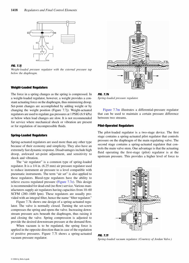
The force in a spring changes as the spring is compressed. Ina weight-loaded regulator, however, a weight provides a con-stant actuating force on the diaphragm, thus minimizing droop.Set-point changes are accomplished by adding weight or bychanging the weight position (Figure 7.7j). Weight-actuatedregulators are used to regulate gas pressures at 1 PSIG (6.9 kPa)or below when load changes are slow. It is not recommendedfor service where mechanical shock or vibration are presentor for regulation of incompressible fluids.
Spring-Loaded Regulators
Spring-actuated regulators are used more than any other typebecause of their economy and simplicity. They also have anextremely fast dynamic response. Disadvantages include highdroop, awkward set-point adjustment, and sensitivity toshock and vibration.
The “air regulator” is a common type of spring-loadedregulator. It is a 1/4 in. (6.25 mm) air pressure regulator usedto reduce instrument air pressure to a level compatible withpneumatic instruments. The term “air set” is also applied tothese regulators. Bleed-type regulators have the ability torelieve excess regulated pressure (Figure 7.7e). This designis recommended for dead-end (no flow) service. Various man-ufacturers supply air regulators having capacities from 10–60SCFM (280–1680 lpm). These regulators are usually pro-vided with an integral filter, hence the name “filter regulator.”
Figure 7.7k shows one design of a spring-actuated regu-lator. The valve is normally closed. Turning the set-screwcompresses the spring and opens the valve. Increasing down-stream pressure acts beneath the diaphragm, thus raising itand closing the valve. Spring compression is adjusted toprovide the desired downstream pressure at the demand flow.
When vacuum is to be regulated, the spring force isapplied in the opposite direction than in case of the regulationof positive pressures. Figure 7.7l shows a spring-actuatedvacuum pressure regulator.
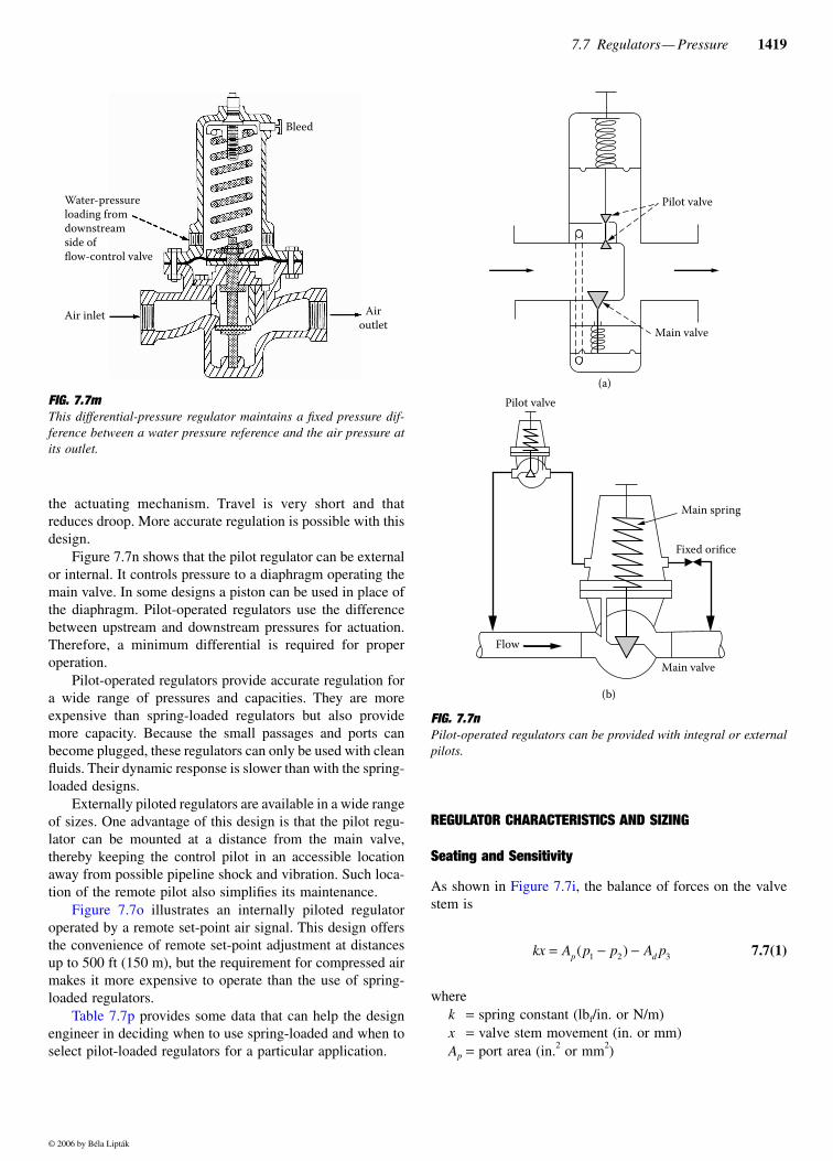
Figure 7.7m illustrates a differential-pressure regulatorthat can be used to maintain a certain pressure differencebetween two streams.
Pilot-Operated Regulators
The pilot-loaded regulator is a two-stage device. The firststage contains a spring-actuated pilot regulator that controlspressure on the diaphragm of the main regulating valve. Thesecond stage contains a spring-actuated regulator that con-trols the main valve stem. One advantage is that the actuatingfluid operating the first-stage (pilot) regulator is at theupstream pressure. This provides a higher level of force to
FIG. 7.7j Weight-loaded pressure regulator with the external pressure tapbelow the diaphragm.
FIG. 7.7kSpring-loaded pressure regulator.
FIG. 7.7lSpring-loaded vacuum regulator. (Courtesy of Jordan Valve.)
© 2006 by Béla Lipták
7.7 Regulators— Pressure 1419
the actuating mechanism. Travel is very short and thatreduces droop. More accurate regulation is possible with thisdesign.
Figure 7.7n shows that the pilot regulator can be externalor internal. It controls pressure to a diaphragm operating themain valve. In some designs a piston can be used in place ofthe diaphragm. Pilot-operated regulators use the differencebetween upstream and downstream pressures for actuation.Therefore, a minimum differential is required for properoperation.
Pilot-operated regulators provide accurate regulation fora wide range of pressures and capacities. They are moreexpensive than spring-loaded regulators but also providemore capacity. Because the small passages and ports canbecome plugged, these regulators can only be used with cleanfluids. Their dynamic response is slower than with the spring-loaded designs.
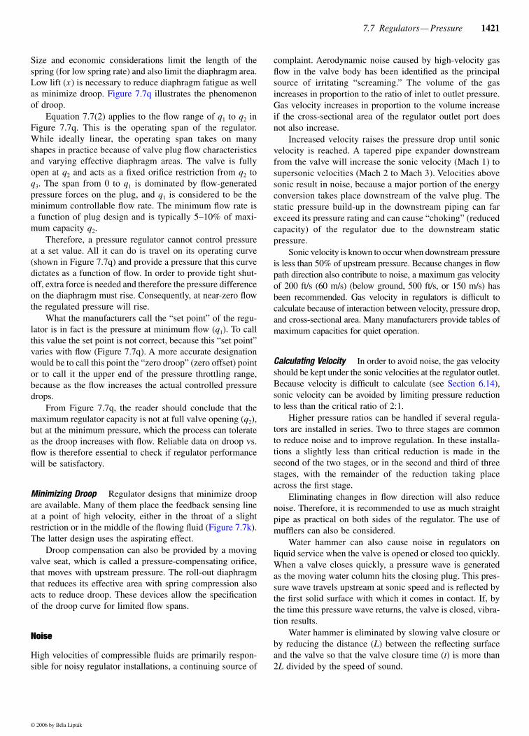
Externally piloted regulators are available in a wide rangeof sizes. One advantage of this design is that the pilot regu-lator can be mounted at a distance from the main valve,thereby keeping the control pilot in an accessible locationaway from possible pipeline shock and vibration. Such loca-tion of the remote pilot also simplifies its maintenance.
Figure 7.7o illustrates an internally piloted regulatoroperated by a remote set-point air signal. This design offersthe convenience of remote set-point adjustment at distancesup to 500 ft (150 m), but the requirement for compressed airmakes it more expensive to operate than the use of spring-loaded regulators.
Table 7.7p provides some data that can help the designengineer in deciding when to use spring-loaded and when toselect pilot-loaded regulators for a particular application.
REGULATOR CHARACTERISTICS AND SIZING
Seating and Sensitivity
As shown in Figure 7.7i, the balance of forces on the valvestem is
7.7(1)
wherek = spring constant (lbf/in. or N/m)x = valve stem movement (in. or mm)Ap = port area (in.2 or mm2)
FIG. 7.7mThis differential-pressure regulator maintains a fixed pressure dif-ference between a water pressure reference and the air pressure atits outlet.
Water-pressureloading fromdownstreamside offlow-control valve
Air inlet Airoutlet
Bleed
FIG. 7.7nPilot-operated regulators can be provided with integral or externalpilots.
Pilot valve
Fixed orifice
Main spring
Main valve
Flow
Main valve
Pilot valve
(a)
(b)
kx A p p A pp d= − −( )1 2 3
© 2006 by Béla Lipták
1420 Regulators and Final Control Elements
p1 = inlet pressure (PSIG or Pa)p2 = outlet pressure or regulated pressure (PSIG or Pa)p3 = diaphragm back-pressure (PSIG or Pa)Ad = diaphragm area (in.2 or mm2)
Inserting into Equation 7.7(1) the typical values of a typicalregulator application will likely result in a relatively largeproduct of Ap(p1 – p2) as compared to Adp3. In other words,the actuating force is comparatively low, and a balanced plugis desirable because it eliminates the term Ap(p1 – p2).
Figure 7.7j shows an essentially balanced, double-seatedplug valve design, which is limited to continuous servicebecause it cannot provide tight shut-off.
Figure 7.7k shows a sliding gate mechanism that is alsobalanced, but this design is not suited for applications withhigh pressure drops. Analysis of the regulator as a feedbackmechanism shows that the balanced plug reduces sensitivityto variations in supply pressure.
Intermittent service requiring tight shut-off necessitatesusing a single-seated valve. Balancing pistons, diaphragms,and ingenious seating configurations can be used to providea balanced plug in a single-seated design, but these devicesare more complex and costly. In valves with port diametersof 1 in. (25 mm) or less, the ratio of diaphragm area to portarea can be made large enough so that balancing is notrequired for moderate pressure drops.
Droop or Offset
The regulator is a complete, self-contained feedback controlloop with proportional-only control action. Thus, the regulatedpressure will be offset by changes in the load disturbancevariables (flow demand, in the case of a pressure-reducingvalve). The offset in regulated pressure with changing flowis called droop. It can be expressed as follows:
7.7(2)
whereq = throughput and the other letters are as defined in
connection with Equation 7.7(1).
Equation 7.7(2) shows that the droop or offset is a functionof the operating pressures and of the regulator design param-eters such as spring rate k, valve lift x, and diaphragm area Ad.
FIG. 7.7o Remote set point provided by pneumatic loading of an internallypiloted regulator valve.
TABLE 7.7p Regulator Selection for Various Service Conditions
RecommendedRegulatorType
Magnitude ofPressure
Reduction
SupplyPressure
VariationsLoad
Variations
Spring-loaded Moderate Small Moderate
Spring-loaded Moderate Large Moderate
Pilot-operated Moderate Large Large
Pilot-operated Large(in one stage)
Moderate Large
Pilot-operatedfirst stage
Large(in two stages)
Large Large(in first stage)
Spring-loadedor pilot-operated
Large(in two stages)
Large Moderate(in second stage)
Set-pointair signal
Pilotvalve
Mainvalve
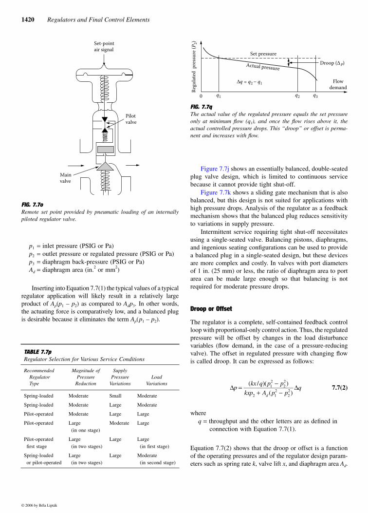
FIG. 7.7q The actual value of the regulated pressure equals the set pressureonly at minimum flow (q1), and once the flow rises above it, theactual controlled pressure drops. This “droop” or offset is perma-nent and increases with flow.
Regu
late
d p
ress
ure (
P 2)
0 q1 q2 q3
Set pressure
Actual pressureDroop (∆P)
Flowdemand
∆q = q2 − q1
∆ ∆pkx q p p
kxp A p pq
d
=−
+ −( / )( )
( )12
22
2 12
22
© 2006 by Béla Lipták
7.7 Regulators— Pressure 1421
Size and economic considerations limit the length of thespring (for low spring rate) and also limit the diaphragm area.Low lift (x) is necessary to reduce diaphragm fatigue as wellas minimize droop. Figure 7.7q illustrates the phenomenonof droop.
Equation 7.7(2) applies to the flow range of q1 to q2 inFigure 7.7q. This is the operating span of the regulator.While ideally linear, the operating span takes on manyshapes in practice because of valve plug flow characteristicsand varying effective diaphragm areas. The valve is fullyopen at q2 and acts as a fixed orifice restriction from q2 toq3. The span from 0 to q1 is dominated by flow-generatedpressure forces on the plug, and q1 is considered to be theminimum controllable flow rate. The minimum flow rate isa function of plug design and is typically 5–10% of maxi-mum capacity q2.
Therefore, a pressure regulator cannot control pressureat a set value. All it can do is travel on its operating curve(shown in Figure 7.7q) and provide a pressure that this curvedictates as a function of flow. In order to provide tight shut-off, extra force is needed and therefore the pressure differenceon the diaphragm must rise. Consequently, at near-zero flowthe regulated pressure will rise.
What the manufacturers call the “set point” of the regu-lator is in fact is the pressure at minimum flow (q1). To callthis value the set point is not correct, because this “set point”varies with flow (Figure 7.7q). A more accurate designationwould be to call this point the “zero droop” (zero offset) pointor to call it the upper end of the pressure throttling range,because as the flow increases the actual controlled pressuredrops.
From Figure 7.7q, the reader should conclude that themaximum regulator capacity is not at full valve opening (q2),but at the minimum pressure, which the process can tolerateas the droop increases with flow. Reliable data on droop vs.flow is therefore essential to check if regulator performancewill be satisfactory.
Minimizing Droop Regulator designs that minimize droopare available. Many of them place the feedback sensing lineat a point of high velocity, either in the throat of a slightrestriction or in the middle of the flowing fluid (Figure 7.7k).The latter design uses the aspirating effect.
Droop compensation can also be provided by a movingvalve seat, which is called a pressure-compensating orifice,that moves with upstream pressure. The roll-out diaphragmthat reduces its effective area with spring compression alsoacts to reduce droop. These devices allow the specificationof the droop curve for limited flow spans.
Noise
High velocities of compressible fluids are primarily respon-sible for noisy regulator installations, a continuing source of
complaint. Aerodynamic noise caused by high-velocity gasflow in the valve body has been identified as the principalsource of irritating “screaming.” The volume of the gasincreases in proportion to the ratio of inlet to outlet pressure.Gas velocity increases in proportion to the volume increaseif the cross-sectional area of the regulator outlet port doesnot also increase.
Increased velocity raises the pressure drop until sonicvelocity is reached. A tapered pipe expander downstreamfrom the valve will increase the sonic velocity (Mach 1) tosupersonic velocities (Mach 2 to Mach 3). Velocities abovesonic result in noise, because a major portion of the energyconversion takes place downstream of the valve plug. Thestatic pressure build-up in the downstream piping can farexceed its pressure rating and can cause “choking” (reducedcapacity) of the regulator due to the downstream staticpressure.
Sonic velocity is known to occur when downstream pressureis less than 50% of upstream pressure. Because changes in flowpath direction also contribute to noise, a maximum gas velocityof 200 ft/s (60 m/s) (below ground, 500 ft/s, or 150 m/s) hasbeen recommended. Gas velocity in regulators is difficult tocalculate because of interaction between velocity, pressure drop,and cross-sectional area. Many manufacturers provide tables ofmaximum capacities for quiet operation.
Calculating Velocity In order to avoid noise, the gas velocityshould be kept under the sonic velocities at the regulator outlet.Because velocity is difficult to calculate (see Section 6.14),sonic velocity can be avoided by limiting pressure reductionto less than the critical ratio of 2:1.
Higher pressure ratios can be handled if several regula-tors are installed in series. Two to three stages are commonto reduce noise and to improve regulation. In these installa-tions a slightly less than critical reduction is made in thesecond of the two stages, or in the second and third of threestages, with the remainder of the reduction taking placeacross the first stage.
Eliminating changes in flow direction will also reducenoise. Therefore, it is recommended to use as much straightpipe as practical on both sides of the regulator. The use ofmufflers can also be considered.
Water hammer can also cause noise in regulators onliquid service when the valve is opened or closed too quickly.When a valve closes quickly, a pressure wave is generatedas the moving water column hits the closing plug. This pres-sure wave travels upstream at sonic speed and is reflected bythe first solid surface with which it comes in contact. If, bythe time this pressure wave returns, the valve is closed, vibra-tion results.
Water hammer is eliminated by slowing valve closure orby reducing the distance (L) between the reflecting surfaceand the valve so that the valve closure time (t) is more than2L divided by the speed of sound.
© 2006 by Béla Lipták
1422 Regulators and Final Control Elements
Cavitation
Cavitation is caused by localized vaporization as the pressureat the vena contracta drops below the vapor pressure of theflowing fluid. As the pressure recovers after the vena con-tracta, these vapor bubbles collapse and can cause vibrationdamage and valve-metal erosion.
The energy for the increase in flow velocity at the valve’svena contracta is obtained from the pressure (potentialenergy) of the flowing fluid, causing a localized pressurereduction. If this localized pressure falls below the vaporpressure of the fluid, it causes temporary vaporization.
Cavitation damage always occurs downstream of the venacontracta, where the pressure recovery occurs in the valve. Itis in this area where the vapor bubbles collapse. Destructionis due to the implosions that generate the extremely high-pressure shock waves in the substantially incompressiblestream (Figure 6.1w). When these waves strike the solid metalsurface of the valve or downstream piping, the damaged metalsurface will give a cinder-like appearance. Cavitation is usu-ally coupled with vibration and makes a sound like that ofrock fragments or gravel flowing through the valve.
Cavitation can be eliminated by altering either the valve,the process, or the installation. The various anticavitation valvedesigns such as the labyrinth (Figure 6.1y) are usually notavailable for regulators. Therefore, cavitation in regulators mustbe eliminated by changing either the process or the installation.
Anticavitation Designs A slight reduction of operating tem-perature can usually be tolerated from a process point of view,and this might be sufficient to lower the vapor pressure suffi-ciently to eliminate cavitation. Similarly, increased upstreamand downstream pressure, with ∆P unaffected, can also relievecavitation. Valves subject to cavitation should be installed atthe lowest possible elevation in the piping system. Moving thevalve closer to the pump will also serve to increase bothupstream and downstream pressures.
If cavitating conditions are unavoidable from the processcondition’s point of view, then it is actually preferable to havenot only cavitation but also some permanent vaporization(flashing) through the valve. This can usually be guaranteedby a slight increase in operating temperature or by decreasingthe outlet pressure. Flashing eliminates cavitation by elimi-nating pressure recovery.
Another way to eliminate cavitation is to install two ormore regulators in series. Cavitation problems can also bealleviated by absorbing some of the pressure drop inbreakdown orifices, chokes (Figure 6.1cc), or partially openblock valves upstream of the pressure-reducing valve. Theamount of cavitation damage is related to the sixth power offlow velocity or to the third power of pressure drop. This isthe reason why reducing ∆P by a factor of two, for example,will result in an eightfold reduction in cavitation destruction.
In some high-pressure let-down stations, it might not bepossible to eliminate cavitation accompanied by erosion orcorrosion, or both. In such installations, one ought to consider
the use of inexpensive choke fittings (shown in Figure 6.1cc)instead of control valves. The fixed chokes can be of differentcapacities and be isolated by full-bore on/off valves, provid-ing a means of matching the process flow with the openingof the required number of chokes. If n chokes are installed,this will allow for operating at (2n–1) flow rates. If, forexample, the chokes discharge into the vapor space of a tank,this will minimize cavitation damage because the bubbleswill not be collapsing near any metallic surfaces.
Sizing and Rangeability
Oversizing is the most common error in regulator selection.The droop characteristic makes a larger valve attractive,because a greater capacity is obtainable for the same droop.The larger valve also reduces noise because of its largerpassages. These apparent advantages are offset by highercost, severe seat wear, and poor regulation.
The limitation on sizing is rangeability. Rangeability var-ies from 4 to 1 for a steam regulator, which cannot be operatedclose to its seat because of wire drawing, to over 50 to 1 foran air regulator. Figure 7.7q illustrates rangeability (q2/q1).Minimum flow, q1, is 5–10% of q2, depending on the seatconfiguration.
Maximum flow is not necessarily q2 but is determined bymaximum acceptable droop. A typical rangeability is 10 to1. An oversized regulator may not be able to control at theminimum flow because it falls outside its rangeability.
Regulators are sized on the basis of tabulated data orvalve coefficients (Cv) provided by the manufacturer. Size ischosen to accommodate the maximum flow at minimum pres-sure drop. The valve should ideally operate at 50–60% openunder normal conditions. Catalog information must be usedjudiciously, because capacity and droop may be specified atdifferent points. Rated capacity might result in too high avelocity, or the (external) pressure feedback tap might havebeen located at a different point during testing than in theapplication.
Rangeability is increased by using two regulators in par-allel. In such installations the pressure setpoint of one regu-lator is set 10% higher than the other, so one regulator willbe wide open while the other modulates under high loadconditions. As demand is reduced, the second regulator willclose and the first will modulate. Leakage in the secondregulator must be a minor portion of the capacity of the firstregulator.
Stability
Stability of the regulator installation depends on the openloop gain. For the regulator shown in Figure 7.7i, open loopgain is defined as
7.7(3)KA p p
kxpod=
−( )12
22
2
© 2006 by Béla Lipták
7.7 Regulators— Pressure 1423
where Ko is the open loop gain. Comparing this equationwith the one given earlier for droop, it is apparent that anychanges that might decrease droop would increase the open-loop gain and decrease stability, as expected in a feedbackmechanism. Because the regulator has no controller modeadjustments, the maker must choose design parameters thatwill provide an adequate compromise between droop andstability. It can thus be expected that the open-loop gain ofsome applications will be too high, resulting in a noisy andcycling pressure regulator.
Guidelines for a stable installation are few. Difficultiesare generally found after installation. Because the regulatorhas no adjustments it is costly to correct problems. The fol-lowing steps can be considered in stabilizing an installedregulator: (1) Relocation of the pressure-sensing tap. (2)Redesign of the downstream piping to provide more volume.(3) Restricting the pressure feedback line, either by a needlevalve in an external line or by filling an internal line andredrilling it to provide a smaller hole.
Safety
Diaphragm rupture is the most common failure in a regulator.Most regulators fail full open upon diaphragm failure, whichis usually an unsafe condition. A relief valve on the regulatedpressure side is recommended if it is unsafe to allow theincrease in regulated pressure to the level of the supplypressure.
In installations where it is imperative that the user con-tinue to be supplied even on a regulator failure, two regulatorscan be placed in series. In such installations, the secondregulator should have a set point that is 10% higher than thefirst, so that it will remain wide open under normal circum-stances. If the first regulator fails, the second will take overpressure regulation.
Installation
Regulator installation is generally easier than regulator selec-tion. The following installation suggestions will help ensuresatisfactory regulator performance:
1. Steam regulators should be preceded by a separatorand a trap.
2. All regulators should be preceded by a filter or strainer.3. A valve bypass is recommended where it is necessary
to service the regulator while continuing to supplyusers.
4. Use straight lengths of pipe upstream and downstreamto reduce noise.
5. External feedback lines should be 1/4 in. (6.25 mm)pipe or tubing.
6. Locate the pressure feedback tap at a point where itwill not be affected by turbulence, line losses, or sud-den changes in velocity. A distance of 10 ft (3 m) fromthe regulator is recommended.
Bibliography
Adams, R. M., “Don’t Overlook Simple Regulators,” InTech, April 1983.Baumann, H. D., “Why Limited Velocities in Reducing Valves?” Instruments
and Control Systems, September 1965.Beard, C. S., Final Control Elements, Philadelphia: Rimbach Publications
Division, 1969.Beard, C. S., and Marton, F. D., Regulators and Relief Valves, Philadelphia:
Chilton Book Co.Comber, J., and Hockman, P., “Pressure Monitoring: What’s Happening?”
Instruments and Control Systems, April 1980.“Control Valves—Regulator/Safety/Relief/Check,” Measurements and Con-
trol, June 1993.Dickinson, W., “Don’t Overlook Pressure Regulators,” Instruments and Con-
trol Systems, May 1983.Driskell, L. R., Control Valve Selection and Sizing, Research Triangle Park,
NC: ISA, 1983.Fleming, A., “Regulator Station Design,” Instruments and Control Systems,
April 1961.Fluid Controls Institute, “Definitions of Regulator Capacities,” FCI-58-1,
April 1966.Fluid Controls Institute, “Guide to Material Selection for Industrial Regu-
lators,” FCI-65-1.Hall, J., “Monitoring Pressure with Newer Technologies,” Instruments and
Control Systems, April 1979.Kubitz, R., “Valves in Gas Regulators,” Instruments and Control Systems,
April 1966.Law, S., “Measurement and Instrumentation: Automating District Regula-
tors,” Gas Industries, January 2003.Ledeen, H., “A New Look at Valve Regulation,” Instruments and Control
Systems, August 1965.Lipták, B. G., “A Close Look at Pressure Regulators,” Chemical Engineer-
ing, April 13, 1987.Moore, R. L., “The Use and Misuse of Pressure Regulators,” Instrumental
Technology, March 1969.1992–94 Catalog of U.S. & Canadian Valves & Actuators, Washington, D.C.:
Valve Manufacturers Association of America.North American Sourcebook of Valves, Actuators & Control Manufactur-
ers, 6th ed., Washington, D.C.: Valve Manufacturers Association ofAmerica, 2004.
O’Connor, J. P., “12 Points to Consider when Selecting Pressure Regulators,”Plant Engineering, March 1958.
Perrine, E. B., “Pressure Regulators and their Application,” Instruments andControl Systems, September 1965.
Quentzel, D., “A Balance Factor for Pressure Reducing Valves,” ControlEngineering, May 1965.
“Selecting and Sizing Pressure Reducing Regulators,” in Fisher RegulatorHandbook, 2nd ed., Fisher Controls Regulator Division, McKinney,TX, 2001.
Spitzer, D. W., “Remotely Set Pressure Regulators,” InTech, November 1992.Watts, G. R., “Pressure Regulators or Control Valves?” Instrumental Tech-
nology, June 1980.Wilmer, J., Orzechowski, B., and Mackenzie, D., “Component and Design
Optimization, Process Measurement and Control for Colloidal CMPSlurries,” ISA EXPO 2003, Houston, TX, October 2003.
Yedidiah, S., “Effect of Seat Configuration on Pressure Operated ControlValves,” Design News, October 11, 1967.
© 2006 by Béla Lipták
1424 Regulators and Final Control Elements
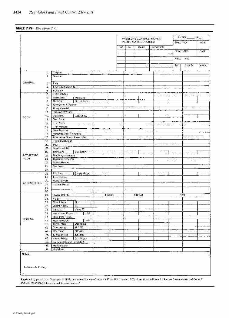
TABLE 7.7s ISA Form 7.7s
© 2006 by Béla Lipták
7.7 Regulators— Pressure 1425
ISA SPECIFICATION FORM (TABLE 7.7s)
Compiling the information necessary to specify a regulatoris best done with the aid of a tabulation sheet. Many largecompanies have their own customized forms. A general-pur-pose form standardized by the Instrumentation, Systems andAutomation Society, formerly the Instrument Society ofAmerica (ISA) is provided below with the instructions forcompleting ISA Form S20.51. The ISA SP20 Committee iscurrently updating all of the S20 Instrument SpecificationForms.
Instructions for ISA Form S20.51
1–4. Identification and service/location. It is assumed thateach tag number is for a single valve.5. Pressure reducing, back-pressure control, or differentialpressure regulator.6. Globe, or Manufacturer’s Standard (MFR. STD.).7. Body connection size and inner valve size.8. Guiding may be top, top and bottom, skirt, or MFR. STD.Select single or double port, if applicable.9. Specify screwed (NPT), flanged, or weld end, and flangerating, such as 150 lb ANSI.10–11. Specify materials.12. Write in “yes” or use checkmark if required.13. Quick open, equal percent, linear, etc.State Characteristic:
L = LinearLV = Linear V PortEP = Equal PercentageEPT = Equal Percentage TurnedEPB = Equal Percentage BalancedQ = Quick OpeningOr use your own code and identify in notes.
14. Refers to seal between body and top works, such asdiaphragm, stuffing box, etc.15. Refers to seat, plug, stem; in general, all internal wettedparts.16. Use only to specify soft seat; otherwise material will besame as trim specified in line 14.17. Use if required.18. Max. allowable sound level dBA 3 ft from pipe and 3 ftdownstream of the valve outlet.19. Actuator may be spring type or springless pressurebalanced.
20. The pilot is an integral or external auxiliary device thatamplifies the force available through an operating medium,usually air.21. Give pressure available and specify medium.22. Refers to valve pressure sensing system. Specify whethercontrolled pressure is sensed internally or by means of anexternal line requiring an additional piping connection.23–24. Specify diaphragm material and pressure or temper-ature limits, if applicable.25. Range over which pressure setting can be made.26. Specification of set pressure does not apply to factorysetting. This must be called for specifically, if required.27. Specify filter regulator, with or without gage, if requiredfor air supply to pilot. Write “yes” or use checkmark.28–29. Specify if strainer is to be furnished with valve. Write“yes” to check off, or give style or model number.30–33. Options available in gas regulators. On line 30, spec-ify “bug-proof ” if required. Specify accessories on lines32–33.34. State liquid, steam, gas units (gpm, lb/hr, ft3/min., etc.)35. Name of fluid and state, whether vapor or liquid, if notapparent.36. State maximum quantity required by process and corre-sponding Cv.37. State operating quantity required by process and corre-sponding Cv.38. The manufacturer shall fill in the valve Cv and FL (liquidpressure) recovery factor without reducers or other acces-sories.39. Operating inlet pressure and pressure differential withunits (psia, PSIG, inches H2O, or Hg). Note at this point thatone might consider how minimum conditions will fit thesizing.40. Maximum inlet pressure if different from normal.41. State the maximum pressure drop in shut-off position todetermine proper actuator size. This is actual difference ininlet and outlet pressure stated in psi, inches of H2O or Hg, etc.42. State °F or °C.43. State operating specific gravity and molecular weight.44. State operating viscosity and its units. State flash at valveoutlet, i.e., of max. flow that will be flashed to vapor becauseof the valve pressure drop.45. In the case of vapors, state the superheat, and in the casesof liquids, state the solids, if present.46. Note vapor pressure of fluid as well as the criticalpressure.47. Give manufacturer’s predicted sound level dBA.48. Complete when available.
© 2006 by Béla Lipták