Embed Size (px)
Citation preview
75G/85G Excavators42.4 kW (56.9 hp)
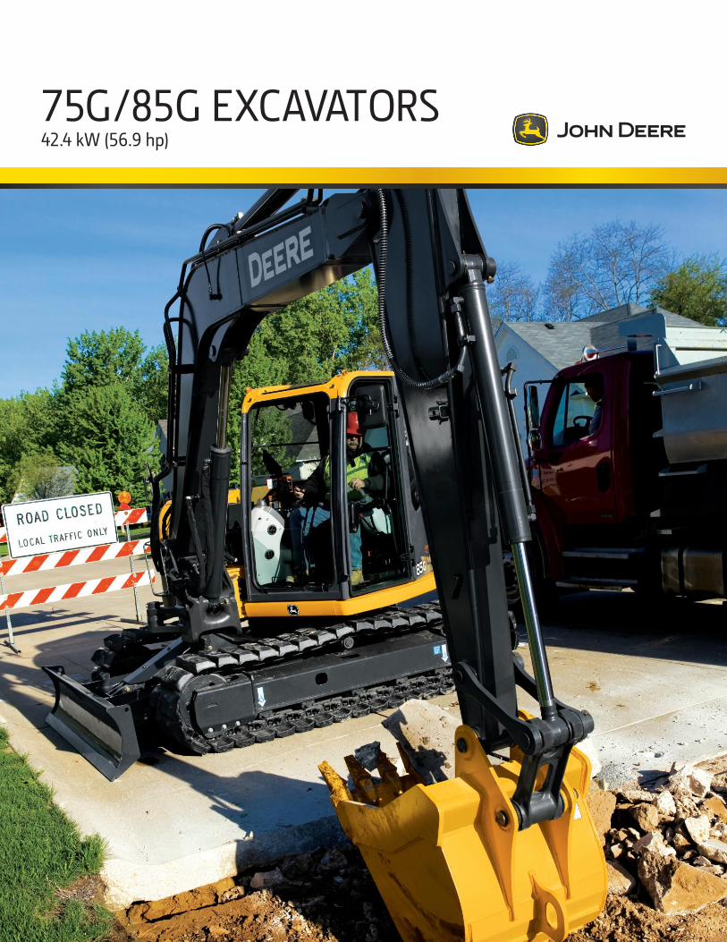
Fit in more productivity. Neither too big nor too small, these right-size excava-
tors are the perfect solution for a wide variety of tasks.
Their reduced-tail-swing conƟgurations provide extra
Ơexibility, enabling them to maneuver nimbly and work
efƟciently in and around congested conditions. What’s
more, the 85G comes equipped with the extra advan-
tage of an independent-swing boom that lets it work
even closer to curbs, parallel to structures, or in the
midst of trafƟc. Inside their spacious, comfortable cabs,
easy-to-navigate enhanced LcD monitors let operators
easily dial-in a wealth of machine info and functionality.
of course, these two meet EPa Final tier 4 (Ft4)/EU
Stage IV regulations, so they’re a perfect Ɵt for your
equipment Ơeet for years to come.
Key speciƟcations 75G 85G
Net rated power 42.4 kW (56.9 hp) 42.4 kW (56.9 hp)
Operating weight 8143 kg (17,952 lb.) 8729 kg (19,244 lb.)
Maximum digging depth 4.61 m (15 ft. 1 in.) 4.51 m (14 ft. 10 in.)
Arm digging force 30.7 kN (6,902 lb.) 30.7 kN (6,902 lb.)
Bucket digging force 46.6 kN (10,476 lb.) 46.6 kN (10,476 lb.)
2
3
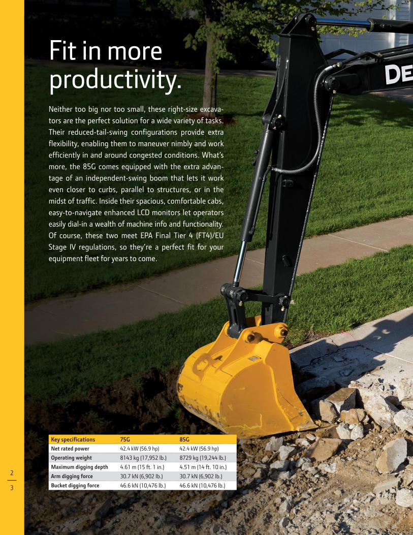
The EPA FT4/EU Stage IV technology in these
excavators is simple, fuel efƟcient, fully integrated, and fully supported. It employs Ɵeld-proven cooled exhaust gas recirculation
(EGr) for reducing Nox, and a diesel partic-
ulate Ɵlter (DPF) and diesel oxidation catalyst
(Doc) to reduce particulate matter.
Large entryways and virtually unrestricted sightlines combine with spacious operator stations to provide all the comfort, conve-nience, and visibility an operator could want.
Undercarriage options include rubber tracks, or sealed and lubricated chain with rubber pads or steel semi-grousers from 450–600-mm (18 to 24 in.) wide. these, plus numerous arm and bucket options, let you spec the right excavator for the way you work.
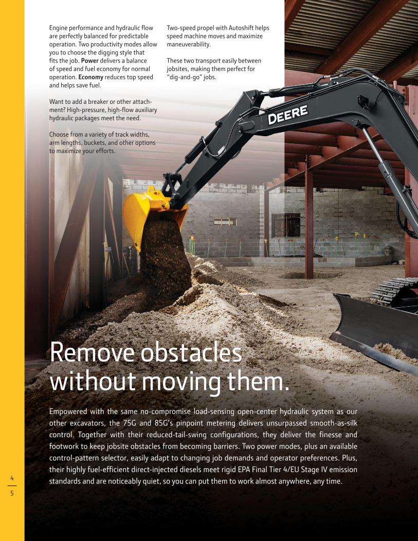
Remove obstacles without moving them.Empowered with the same no-compromise load-sensing open-center hydraulic system as our
other excavators, the 75G and 85G’s pinpoint metering delivers unsurpassed smooth-as-silk
control. Together with their reduced-tail-swing conƟgurations, they deliver the Ɵnesse and
footwork to keep jobsite obstacles from becoming barriers. Two power modes, plus an available
control-pattern selector, easily adapt to changing job demands and operator preferences. Plus,
their highly fuel-efƟcient direct-injected diesels meet rigid EPA Final Tier 4/EU Stage IV emission
standards and are noticeably quiet, so you can put them to work almost anywhere, any time.
Engine performance and hydraulic Ơow
are perfectly balanced for predictable operation. Two productivity modes allow you to choose the digging style that Ɵts the job. Power delivers a balance of speed and fuel economy for normal operation. Economy reduces top speed and helps save fuel.
Want to add a breaker or other attach-ment? High-pressure, high-Ơow auxiliary
hydraulic packages meet the need.
Choose from a variety of track widths, arm lengths, buckets, and other options to maximize your efforts.
Two-speed propel with Autoshift helps
speed machine moves and maximize maneuverability.
These two transport easily between jobsites, making them perfect for “dig-and-go” jobs.
4
5
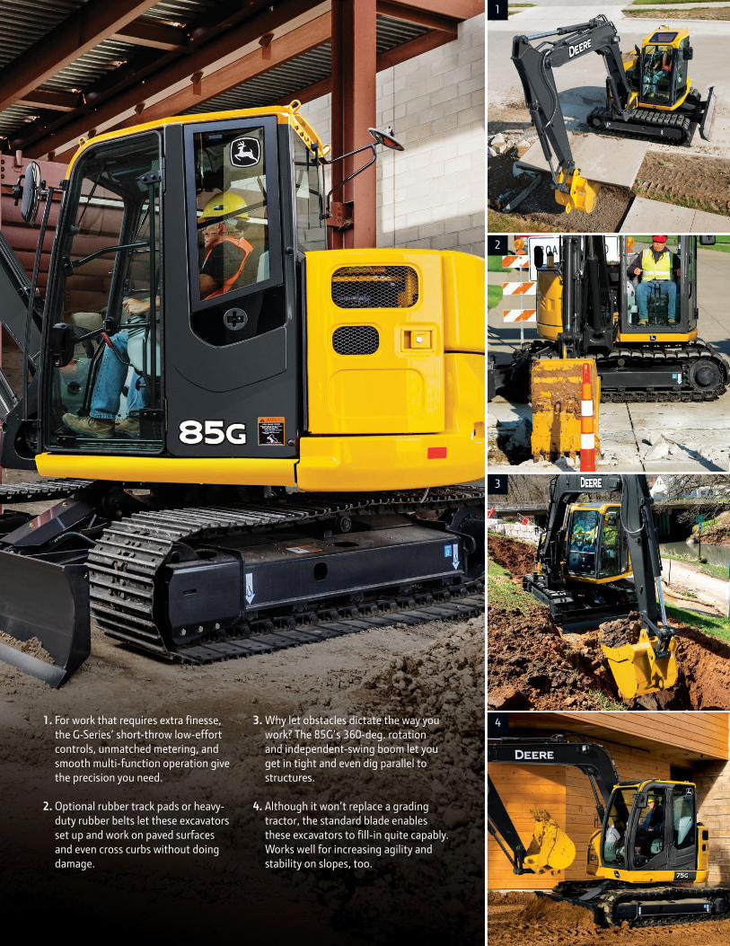
1. For work that requires extra Ɵnesse,
the G-Series’ short-throw low-effort
controls, unmatched metering, and
smooth multi-function operation give
the precision you need.
2. Optional rubber track pads or heavy-
duty rubber belts let these excavators
set up and work on paved surfaces
and even cross curbs without doing
damage.
3. Why let obstacles dictate the way you
work? The 85G’s 360-deg. rotation
and independent-swing boom let you
get in tight and even dig parallel to
structures.
4. Although it won’t replace a grading
tractor, the standard blade enables
these excavators to Ɵll-in quite capably.
Works well for increasing agility and
stability on slopes, too.
1
2
3
4
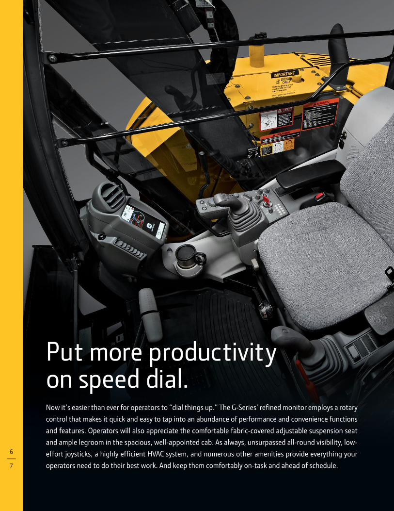
Now it’s easier than ever for operators to “dial things up.” The G-Series’ reƟned monitor employs a rotary
control that makes it quick and easy to tap into an abundance of performance and convenience functions
and features. Operators will also appreciate the comfortable fabric-covered adjustable suspension seat
and ample legroom in the spacious, well-appointed cab. As always, unsurpassed all-round visibility, low-
effort joysticks, a highly efƟcient HVAC system, and numerous other amenities provide everything your
operators need to do their best work. And keep them comfortably on-task and ahead of schedule.
Put more productivity on speed dial.
6
7
1
2
3
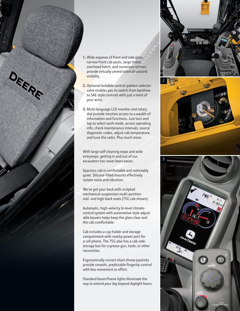
1. Wide expanse of front and side glass, narrow front cab posts, large tinted overhead hatch, and numerous mirrors provide virtually unrestricted all-around visibility.
2. Optional lockable control-pattern selector valve enables you to switch from backhoe- to SAE-style controls with just a twist of your wrist.
3. Multi-language LCD monitor and rotary dial provide intuitive access to a wealth of information and functions. Just turn and tap to select work mode, access operating info, check maintenance intervals, source diagnostic codes, adjust cab temperature, and tune the radio. Plus much more.
With large self-cleaning steps and wide entryways, getting in and out of our excavators has never been easier.
Spacious cab is comfortable and noticeably quiet. Silicone-Ɵlled mounts effectively
isolate noise and vibration.
We’ve got your back with sculpted mechanical-suspension multi-position mid- and high-back seats (75G cab shown).
Automatic, high-velocity bi-level climate-control system with automotive-style adjust-able louvers helps keep the glass clear and the cab comfortable.
Cab includes a cup holder and storage compartment with nearby power port for a cell phone. The 75G also has a cab-side storage box for a grease gun, tools, or other necessities.
Ergonomically correct short-throw joysticks provide smooth, predictable Ɵngertip control
with less movement or effort.
Standard boom/frame lights illuminate the way to extend your day beyond daylight hours.
1 2
a John Deere exclusive, three welded bulkheads within the boom resist torsional stress for unsurpassed durability.
rigid, reinforced D-channel side frames resist impacts, providing maximum cab and component protection.
oil-impregnated bushings enhance durability and extend grease inter-vals to 500 hours for the arm-and-boom joint and 100 hours for the bucket joint.
Durable shields deƠect material and
impacts, protecting the blade cylinder and propel motors.
tungsten-carbide coating creates an extremely wear-resistant surface to protect the all-important bucket-to-arm joint.
viscous fan continuously adjusts speed as necessary for effective cooling. Helps reduce noise and fuel consumption, too.
to help prevent accidental machine movement, a spring-applied, hydraulically released park brake automatically engages when a control lever is released.
Wet-disc swing brake delivers long-term maintenance-free performance.
Just like you, our 75G and 85G Excavators won’t quit. These
dependable workers deliver unsurpassed reliability, with job-proven
digging structures and hydraulic, electrical, and undercarriage
components. Their highly efƟcient cooling systems keep things
running cool, even in high altitudes or tough environments. other
durability-enhancing “extras” include tungsten-carbide-coated
wear surfaces and oil-impregnated bushings. When you know how
they’re built, you’ll run a Deere.
Nothing runs likethis Deere.
8
9
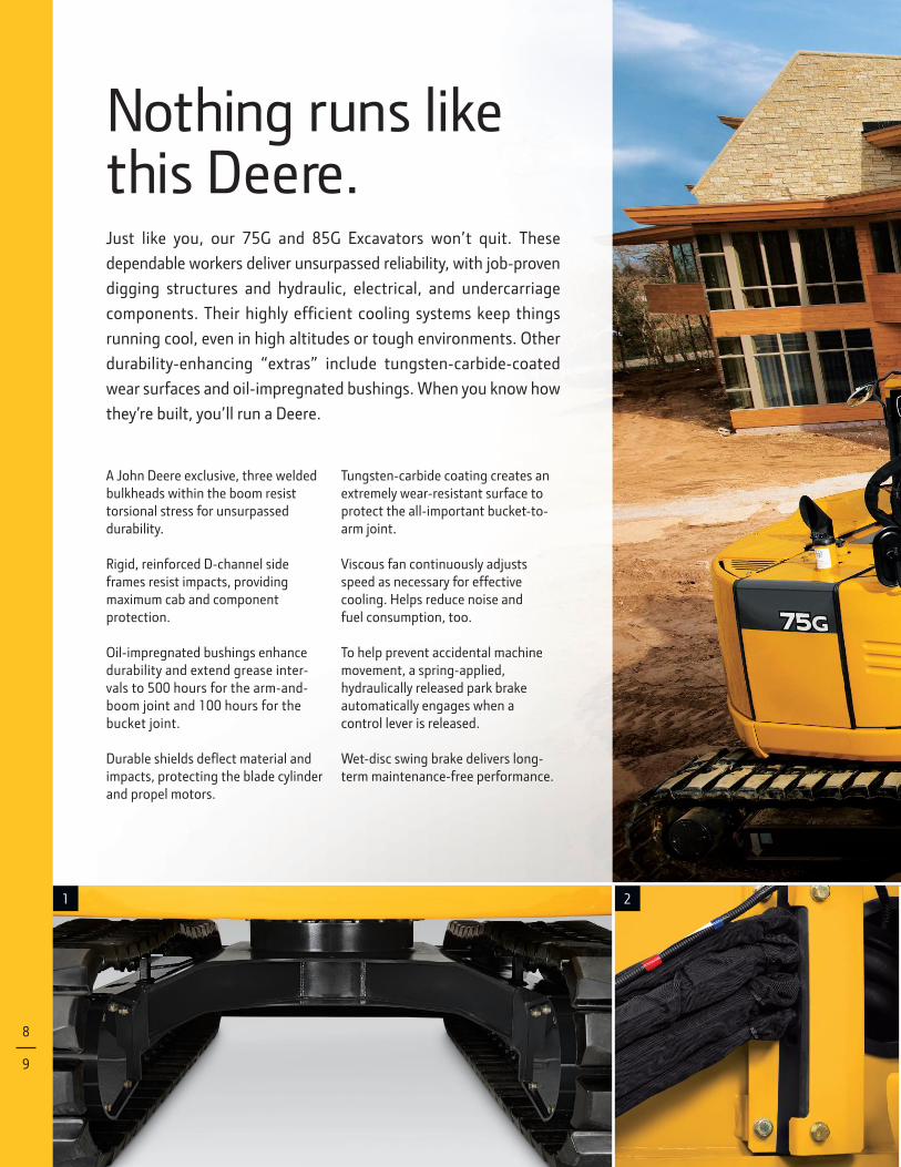
1. Box-section track frames, thick-plate single-sheet mainframe, and large swing bearing deliver rock-solid durability.
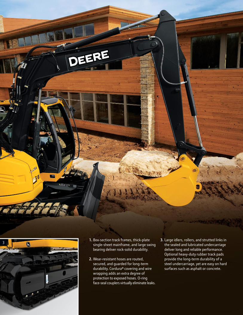
2. Wear-resistant hoses are routed, secured, and guarded for long-term durability. cordura® covering and wire wrapping adds an extra degree of protection to exposed hoses. o-ring face-seal couplers virtually eliminate leaks.
3. Large idlers, rollers, and strutted links in the sealed and lubricated undercarriage deliver long and reliable performance.optional heavy-duty rubber track pads provide the long-term durability of a steel undercarriage, yet are easy on hard surfaces such as asphalt or concrete.
3
It’s likely that it was the G-Series’ compact stature that caught your eye.
But it’s their reduced daily operating costs that’ll really turn your head.
Daily and periodic maintenance are quick, easy, and convenient, with
large, easy-open doors providing wide-open access to grouped service
points. Extended hydraulic and engine oil-change intervals reduce
downtime and expense. Plus the easy-to-read LCD monitor lets you
track Ơuid-maintenance intervals to help manage uptime.
Operating costs are reduced, too.
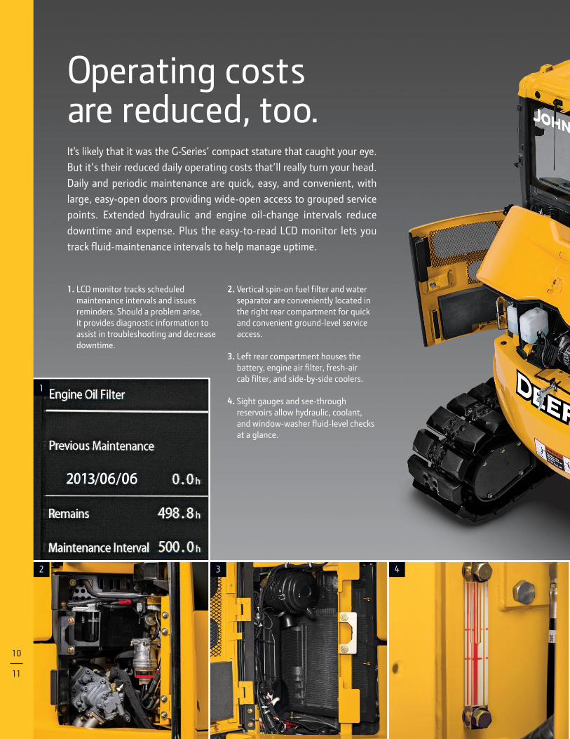
1. LCD monitor tracks scheduled maintenance intervals and issues reminders. Should a problem arise, it provides diagnostic information to assist in troubleshooting and decrease downtime.
2. Vertical spin-on fuel Ɵlter and water
separator are conveniently located in the right rear compartment for quick and convenient ground-level service access.
3. Left rear compartment houses the battery, engine air Ɵlter, fresh-air cab Ɵlter, and side-by-side coolers.
4. Sight gauges and see-through reservoirs allow hydraulic, coolant, and window-washer Ơuid-level checks
at a glance.
2 3 4
1
10
11
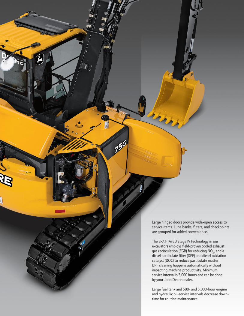
Large hinged doors provide wide-open access to service items. Lube banks, Ɵlters, and checkpoints
are grouped for added convenience.
The EPA FT4/EU Stage IV technology in our
excavators employs Ɵeld-proven cooled exhaust
gas recirculation (EGr) for reducing Nox, and a
diesel particulate Ɵlter (DPF) and diesel oxidation
catalyst (Doc) to reduce particulate matter. DPF cleaning happens automatically without impacting machine productivity. Minimum service interval is 3,000 hours and can be done by your John Deere dealer.
Large fuel tank and 500- and 5,000-hour engine and hydraulic oil-service intervals decrease down-time for routine maintenance.
75G
12
13
Engine 75G
Manufacturer and Model Yanmar 4TNV98C
Non-Road Emission Standard EPA Final Tier 4/EU Stage IV
Net Power (ISO 9249) 42.4 kW (56.9 hp) at 2,000 rpm
Cylinders 4
Displacement 3.3 L (202 cu. in.)
Aspiration Natural
Off-Level Capacity 70% (35 deg.)
Cooling
Variable-speed fan; viscous clutch
Powertrain
2-speed propel with automatic shift
Maximum Travel Speed
Low 3.1 km/h (1.9 mph)
High 5.0 km/h (3.1 mph)
Drawbar Pull 6650 kgf (14,661 lb.)
Hydraulics
Open center, load sensing
Main Pumps 3 variable-displacement axial-piston pumps
Maximum Pump Flow 2 x 72 + 56 L/m (2 x 19 + 15 gpm)
Pilot Pump 1 gear
Maximum Rated Flow 20 L/m (5.3 gpm)
System Relief Pressure 3900 kPa (566 psi)
System Operating Pressure
Implement Circuits 26 000 kPa (3,771 psi)
Travel Circuits 31 400 kPa (4,554 psi)
Swing Circuits 25 200 kPa (3,655 psi)
Controls Pilot levers, short stroke, low effort; hydraulic pilot controls with shutoff lever
Cylinders
Heat-treated, chrome-plated, polished cylinder rods; hardened steel (replaceable bushings) pivot pins
Bore Rod Diameter Stroke
Boom (1) 115 mm (4.5 in.) 65 mm (2.6 in.) 885 mm (34.8 in.)
Arm (1) 95 mm (3.7 in.) 60 mm (2.4 in.) 900 mm (35.4 in.)
Bucket (1) 85 mm (3.3 in.) 55 mm (2.2 in.) 730 mm (28.7 in.)
Electrical
Batteries 2 x 12 volt
Battery Capacity 2 x 450 CCA
Alternator Rating 50 amp
Work Lights 2 halogen: 1 mounted on boom and 1 mounted on frame
Undercarriage
Rollers (each side)
Carrier 1
Track 5
Shoes (each side) 40
Track
Adjustment Hydraulic
Chain Sealed and lubricated
Swing Mechanism
Swing Speed 10.5 rpm
Swing Torque 16 600 Nm (12,244 lb.-ft.)
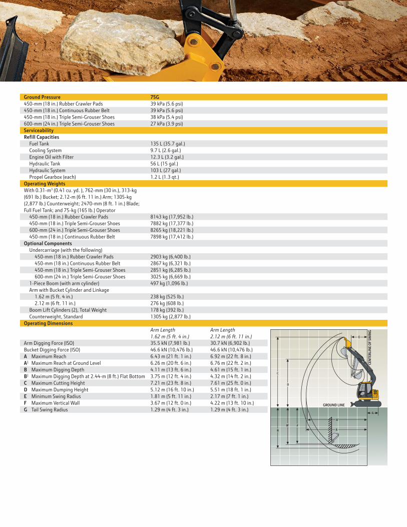
Operating Dimensions
Arm Length
1.62 m (5 ft. 4 in.)
Arm Length
2.12 m (6 ft. 11 in.)
Arm Digging Force (ISO) 35.5 kN (7,981 lb.) 30.7 kN (6,902 lb.)
Bucket Digging Force (ISO) 46.6 kN (10,476 lb.) 46.6 kN (10,476 lb.)
A Maximum Reach 6.43 m (21 ft. 1 in.) 6.92 m (22 ft. 8 in.)
A| Maximum Reach at Ground Level 6.26 m (20 ft. 6 in.) 6.76 m (22 ft. 2 in.)
B Maximum Digging Depth 4.11 m (13 ft. 6 in.) 4.61 m (15 ft. 1 in.)
B| Maximum Digging Depth at 2.44-m (8 ft.) Flat Bottom 3.75 m (12 ft. 4 in.) 4.32 m (14 ft. 2 in.)
C Maximum Cutting Height 7.21 m (23 ft. 8 in.) 7.61 m (25 ft. 0 in.)
D Maximum Dumping Height 5.12 m (16 ft. 10 in.) 5.51 m (18 ft. 1 in.)
E Minimum Swing Radius 1.81 m (5 ft. 11 in.) 2.17 m (7 ft. 1 in.)
F Maximum Vertical Wall 3.67 m (12 ft. 0 in.) 4.22 m (13 ft. 10 in.)
G Tail Swing Radius 1.29 m (4 ft. 3 in.) 1.29 m (4 ft. 3 in.)
Ground Pressure 75G
450-mm (18 in.) Rubber Crawler Pads 39 kPa (5.6 psi)
450-mm (18 in.) Continuous Rubber Belt 39 kPa (5.6 psi)
450-mm (18 in.) Triple Semi-Grouser Shoes 38 kPa (5.4 psi)
600-mm (24 in.) Triple Semi-Grouser Shoes 27 kPa (3.9 psi)
Serviceability
ReƟll Capacities
Fuel Tank 135 L (35.7 gal.)
Cooling System 9.7 L (2.6 gal.)
Engine Oil with Filter 12.3 L (3.2 gal.)
Hydraulic Tank 56 L (15 gal.)
Hydraulic System 103 L (27 gal.)
Propel Gearbox (each) 1.2 L (1.3 qt.)
Operating Weights
With 0.31-m3 (0.41 cu. yd. ), 762-mm (30 in.), 313-kg
(691 lb.) Bucket; 2.12-m (6 ft. 11 in.) Arm; 1305-kg
(2,877 lb.) Counterweight; 2470-mm (8 ft. 1 in.) Blade;
Full Fuel Tank; and 75-kg (165 lb.) Operator
450-mm (18 in.) Rubber Crawler Pads 8143 kg (17,952 lb.)
450-mm (18 in.) Triple Semi-Grouser Shoes 7882 kg (17,377 lb.)
600-mm (24 in.) Triple Semi-Grouser Shoes 8265 kg (18,221 lb.)
450-mm (18 in.) Continuous Rubber Belt 7898 kg (17,412 lb.)
Optional Components
Undercarriage (with the following)
450-mm (18 in.) Rubber Crawler Pads 2903 kg (6,400 lb.)
450-mm (18 in.) Continuous Rubber Belt 2867 kg (6,321 lb.)
450-mm (18 in.) Triple Semi-Grouser Shoes 2851 kg (6,285 lb.)
600-mm (24 in.) Triple Semi-Grouser Shoes 3025 kg (6,669 lb.)
1-Piece Boom (with arm cylinder) 497 kg (1,096 lb.)
Arm with Bucket Cylinder and Linkage
1.62 m (5 ft. 4 in.) 238 kg (525 lb.)
2.12 m (6 ft. 11 in.) 276 kg (608 lb.)
Boom Lift Cylinders (2), Total Weight 178 kg (392 lb.)
Counterweight, Standard 1305 kg (2,877 lb.)
CE
NT
ER
LIN
E O
F S
WIN
G
E
D
C
F
G
GROUND LINE
A'
A
B'
B
14
15
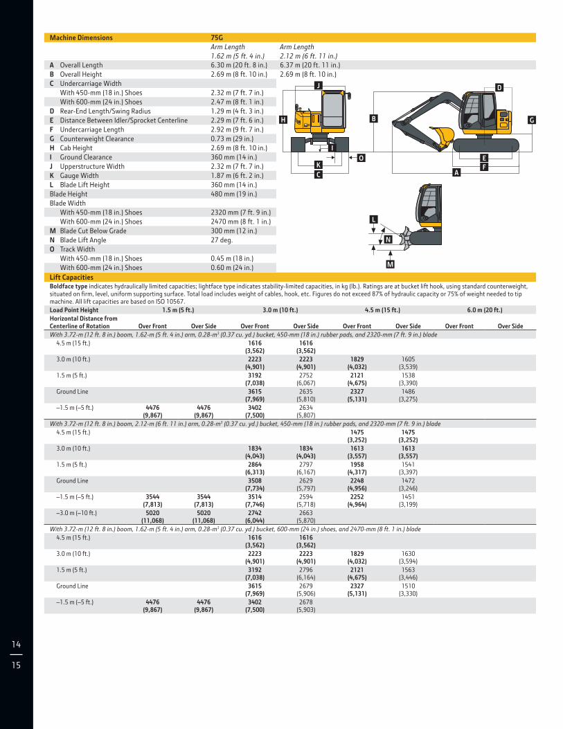
Machine Dimensions 75G
Arm Length
1.62 m (5 ft. 4 in.)
Arm Length
2.12 m (6 ft. 11 in.)
A Overall Length 6.30 m (20 ft. 8 in.) 6.37 m (20 ft. 11 in.)
B Overall Height 2.69 m (8 ft. 10 in.) 2.69 m (8 ft. 10 in.)
C Undercarriage Width
With 450-mm (18 in.) Shoes 2.32 m (7 ft. 7 in.)
With 600-mm (24 in.) Shoes 2.47 m (8 ft. 1 in.)
D Rear-End Length/Swing Radius 1.29 m (4 ft. 3 in.)
E Distance Between Idler/Sprocket Centerline 2.29 m (7 ft. 6 in.)
F Undercarriage Length 2.92 m (9 ft. 7 in.)
G Counterweight Clearance 0.73 m (29 in.)
H Cab Height 2.69 m (8 ft. 10 in.)
I Ground Clearance 360 mm (14 in.)
J Upperstructure Width 2.32 m (7 ft. 7 in.)
K Gauge Width 1.87 m (6 ft. 2 in.)
L Blade Lift Height 360 mm (14 in.)
Blade Height 480 mm (19 in.)
Blade Width
With 450-mm (18 in.) Shoes 2320 mm (7 ft. 9 in.)
With 600-mm (24 in.) Shoes 2470 mm (8 ft. 1 in.)
M Blade Cut Below Grade 300 mm (12 in.)
N Blade Lift Angle 27 deg.
O Track Width
With 450-mm (18 in.) Shoes 0.45 m (18 in.)
With 600-mm (24 in.) Shoes 0.60 m (24 in.)
J
H
O
I
K
C
B
D
G
E
FA
L
M
N
Lift CapacitiesBoldface type indicates hydraulically limited capacities; lightface type indicates stability-limited capacities, in kg (lb.). Ratings are at bucket lift hook, using standard counterweight, situated on Ɵrm, level, uniform supporting surface. Total load includes weight of cables, hook, etc. Figures do not exceed 87% of hydraulic capacity or 75% of weight needed to tip machine. All lift capacities are based on ISO 10567.
Load Point Height 1.5 m (5 ft.) 3.0 m (10 ft.) 4.5 m (15 ft.) 6.0 m (20 ft.)
Horizontal Distance from Centerline of Rotation
Over Front
Over Side
Over Front
Over Side
Over Front
Over Side
Over Front
Over Side
With 3.72-m (12 ft. 8 in.) boom, 1.62-m (5 ft. 4 in.) arm, 0.28-m3 (0.37 cu. yd.) bucket, 450-mm (18 in.) rubber pads, and 2320-mm (7 ft. 9 in.) blade
4.5 m (15 ft.) 1616 (3,562)
1616 (3,562)
3.0 m (10 ft.) 2223 (4,901)
2223 (4,901)
1829 (4,032)
1605 (3,539)
1.5 m (5 ft.) 3192 (7,038)
2752 (6,067)
2121 (4,675)
1538 (3,390)
Ground Line 3615 (7,969)
2635 (5,810)
2327 (5,131)
1486 (3,275)
–1.5 m (–5 ft.) 4476 (9,867)
4476 (9,867)
3402 (7,500)
2634 (5,807)
With 3.72-m (12 ft. 8 in.) boom, 2.12-m (6 ft. 11 in.) arm, 0.28-m3 (0.37 cu. yd.) bucket, 450-mm (18 in.) rubber pads, and 2320-mm (7 ft. 9 in.) blade
4.5 m (15 ft.) 1475 (3,252)
1475 (3,252)
3.0 m (10 ft.) 1834 (4,043)
1834 (4,043)
1613 (3,557)
1613 (3,557)
1.5 m (5 ft.) 2864 (6,313)
2797 (6,167)
1958 (4,317)
1541 (3,397)
Ground Line 3508 (7,734)
2629 (5,797)
2248 (4,956)
1472 (3,246)
–1.5 m (–5 ft.) 3544 (7,813)
3544 (7,813)
3514 (7,746)
2594 (5,718)
2252 (4,964)
1451 (3,199)
–3.0 m (–10 ft.) 5020 (11,068)
5020 (11,068)
2742 (6,044)
2663 (5,870)
With 3.72-m (12 ft. 8 in.) boom, 1.62-m (5 ft. 4 in.) arm, 0.28-m3 (0.37 cu. yd.) bucket, 600-mm (24 in.) shoes, and 2470-mm (8 ft. 1 in.) blade
4.5 m (15 ft.) 1616 (3,562)
1616 (3,562)
3.0 m (10 ft.) 2223 (4,901)
2223 (4,901)
1829 (4,032)
1630 (3,594)
1.5 m (5 ft.) 3192 (7,038)
2796 (6,164)
2121 (4,675)
1563 (3,446)
Ground Line 3615 (7,969)
2679 (5,906)
2327 (5,131)
1510 (3,330)
–1.5 m (–5 ft.) 4476 (9,867)
4476 (9,867)
3402 (7,500)
2678 (5,903)
Lift Capacities (continued) 75GBoldface type indicates hydraulically limited capacities; lightface type indicates stability-limited capacities, in kg (lb.). Ratings are at bucket lift hook, using standard counterweight, situated on Ɵrm, level, uniform supporting surface. Total load includes weight of cables, hook, etc. Figures do not exceed 87% of hydraulic capacity or 75% of weight needed to tip machine. All lift capacities are based on ISO 10567.
Load Point Height 1.5 m (5 ft.) 3.0 m (10 ft.) 4.5 m (15 ft.) 6.0 m (20 ft.)
Horizontal Distance from Centerline of Rotation
Over Front
Over Side
Over Front
Over Side
Over Front
Over Side
Over Front
Over Side
With 3.72-m (12 ft. 8 in.) boom, 2.12-m (6 ft. 11 in.) arm, 0.28-m3 (0.37 cu. yd.) bucket, 600-mm (24 in.) shoes, and 2470-mm (8 ft. 1 in.) blade
4.5 m (15 ft.) 1475 (3,252)
1475 (3,252)
3.0 m (10 ft.) 1834 (4,043)
1834 (4,043)
1613 (3,557)
1613 (3,557)
1.5 m (5 ft.) 2864 (6,313)
2841 (6,263)
1958 (4,317)
1566 (3,452)
Ground Line 3508 (7,734)
2673 (5,893)
2248 (4,956)
1497 (3,301)
–1.5 m (–5 ft.) 3544 (7,813)
3544 (7,813)
3514 (7,746)
2637 (5,814)
2252 (4,964)
1476 (3,254)
–3.0 m (–10 ft.) 5020 (11,068)
5020 (11,068)
2742 (6,044)
2707 (5,967)
With 3.72-m (12 ft. 8 in.) boom, 1.62-m (5 ft. 4 in.) arm, 0.28-m3 (0.37 cu. yd.) bucket, 450-mm (18 in.) continuous rubber belt, and 2470-mm (8 ft. 1 in.) blade
3.0 m (10 ft.) 2241 (4,940)
2241 (4,940)
1.5 m (5 ft.) 3207 (7,070)
2608 (5,750)
Ground Line 3620 (7,980)
2499 (5,510)
2327 (5,130)
1415 (3,120)
–1.5 m (–5 ft.) 4527 (9,980)
4527 (9,980)
3393 (7,480)
2499 (5,510)
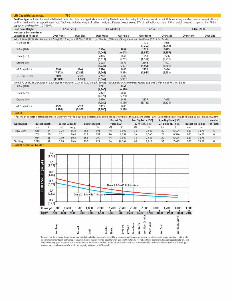
BucketsA full line of buckets is offered to meet a wide variety of applications. Replaceable cutting edges are available through John Deere Parts. Optional side cutters add 150 mm (6 in.) to bucket widths.
Type Bucket
Bucket Width
Bucket Capacity
Bucket Weight
Bucket Dig
Force (ISO)
Arm Dig Force (ISO)
1.62 m (5 ft. 4 in.)
Arm Dig Force (ISO)
2.12 m (6 ft. 11 in.)
Bucket Tip Radius
Number
of Teeth
mm in. m3 cu. yd. kg lb. kN lb. kN lb. kN lb. mm in.
Heavy Duty 610 24 0.24 0.31 268 591 44 9,892 34 7,545 29 6,524 883 34.76 5
762 30 0.31 0.41 313 691 44 9,892 34 7,545 29 6,524 883 34.76 6
914 36 0.39 0.51 358 790 44 9,892 34 7,545 29 6,524 883 34.76 7
Ditching 1219 48 0.49 0.64 330 727 64 14,344 40 8,911 33 7,473 907 35.69 0
Bucket Selection Guide*
1.0(1.25)
0.6(0.75)
2,000 2,200 2,600 3,200lb./cu. yd.
kg/m3
BU
CK
ET
SIZ
E m
(cu
. yd
.)3
1,600 3,400
0.2(0.25)
0.4(0.50)
0.8(1.00)
1.2(1.50)
1,200 1,400 1,800 2,400 2,800 3,000 3,600
Wet
Pea
t
Top
soil
Co
al
Cal
ich
e
Shal
e
Dry
San
d
Dry
Cla
y
Lim
esto
ne
Wet
Ear
th
Wet
Cla
y, G
ran
ite
Mo
ist
San
d
Wet
San
d
Wet
San
d, G
rave
l
1300
Contact your John Deere dealer for optimum bucket and attachment selections. These recommendations are for general conditions and average use. Does not includeoptional equipment such as thumbs or couplers. Larger buckets may be possible when using light materials, for flat and level operations, less compacted materials, andvolume loading applications such as mass-excavation applications in ideal conditions. Smaller buckets are recommended for adverse conditions such as off-level appli-cations, rocks, and uneven surfaces. Bucket capacity indicated is SAE heaped.
*
700 800 900 1000 1100 1200 20001400 1500 1600 1700 1800 1900 2100
Deere 2.12-m (6 ft. 11 in.) Arm
Deere 1.62-m (5 ft. 4 in.) Arm
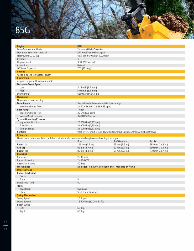
85G
16
17
Engine 85G
Manufacturer and Model Yanmar 4TNV98C-WHBW
Non-Road Emission Standard EPA Final Tier 4/EU Stage IV
Net Power (ISO 9249) 42.4 kW (56.9 hp) at 2,000 rpm
Cylinders 4
Displacement 3.3 L (202 cu. in.)
Aspiration Natural
Off-Level Capacity 70% (35 deg.)
Cooling
Variable-speed fan; viscous clutch
Powertrain
2-speed propel with automatic shift
Maximum Travel Speed
Low 3.1 km/h (1.9 mph)
High 5.0 km/h (3.1 mph)
Drawbar Pull 6650 kgf (14,661 lb.)
Hydraulics
Open center, load sensing
Main Pumps 3 variable-displacement axial-piston pumps
Maximum Pump Flow 2 x 72 + 56 L/m (2 x 19 + 15 gpm)
Pilot Pump 1 gear
Maximum Rated Flow 20 L/m (5.3 gpm)
System Relief Pressure 3900 kPa (566 psi)
System Operating Pressure
Implement Circuits 26 000 kPa (3,771 psi)
Travel Circuits 31 400 kPa (4,554 psi)
Swing Circuits 25 000 kPa (3,626 psi)
Controls Pilot levers, short stroke, low effort; hydraulic pilot controls with shutoff lever
Cylinders
Heat-treated, chrome-plated, polished cylinder rods; hardened steel (replaceable bushings) pivot pins
Bore Rod Diameter Stroke
Boom (1) 115 mm (4.5 in.) 65 mm (2.6 in.) 885 mm (34.8 in.)
Arm (1) 95 mm (3.7 in.) 60 mm (2.4 in.) 900 mm (35.4 in.)
Bucket (1) 85 mm (3.3 in.) 55 mm (2.2 in.) 730 mm (28.7 in.)
Electrical
Batteries 2 x 12 volt
Battery Capacity 2 x 450 CCA
Alternator Rating 50 amp
Work Lights 2 halogen: 1 mounted on boom and 1 mounted on frame
Undercarriage
Rollers (each side)
Carrier 1
Track 5
Shoes (each side) 40
Track
Adjustment Hydraulic
Chain Sealed and lubricated
Swing Mechanism
Swing Speed 10.5 rpm
Swing Torque 16 600 Nm (12,244 lb.-ft.)
Boom Swing
Left 60 deg.
Right 60 deg.
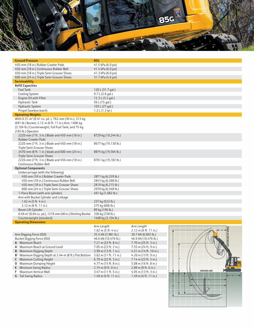
Ground Pressure 85G
450-mm (18 in.) Rubber Crawler Pads 41.5 kPa (6.0 psi)
450-mm (18 in.) Continuous Rubber Belt 41.4 kPa (6.0 psi)
450-mm (18 in.) Triple Semi-Grouser Shoes 41.3 kPa (6.0 psi)
600-mm (24 in.) Triple Semi-Grouser Shoes 31.7 kPa (4.6 psi)
Serviceability
ReƟll Capacities
Fuel Tank 120 L (31.7 gal.)
Cooling System 9.7 L (2.6 gal.)
Engine Oil with Filter 12.3 L (3.2 gal.)
Hydraulic Tank 56 L (15 gal.)
Hydraulic System 103 L (27 gal.)
Propel Gearbox (each) 1.2 L (1.3 qt.)
Operating Weights
With 0.31-m3 (0.41 cu. yd. ), 762-mm (30 in.), 313-kg
(691 lb.) Bucket; 2.12-m (6 ft. 11 in.) Arm; 1408-kg
(3,104 lb.) Counterweight; Full Fuel Tank; and 75-kg
(165 lb.) Operator
2220-mm (7 ft. 3 in.) Blade and 450-mm (18 in.)
Rubber Crawler Pads
8729 kg (19,244 lb.)
2220-mm (7 ft. 3 in.) Blade and 450-mm (18 in.)
Triple Semi-Grouser Shoes
8677 kg (19,130 lb.)
2470-mm (8 ft. 1 in.) blade and 600-mm (24 in.)
Triple Semi-Grouser Shoes
8874 kg (19,564 lb.)
2220-mm (7 ft. 3 in.) Blade and 450-mm (18 in.)
Continuous Rubber Belt
8701 kg (19,182 lb.)
Optional Components
Undercarriage (with the following)
450-mm (18 in.) Rubber Crawler Pads 2871 kg (6,329 lb.)
450-mm (18 in.) Continuous Rubber Belt 2843 kg (6,268 lb.)
450-mm (18 in.) Triple Semi-Grouser Shoes 2819 kg (6,215 lb.)
600-mm (24 in.) Triple Semi-Grouser Shoes 2970 kg (6,548 lb.)
1-Piece Boom (with arm cylinder) 491 kg (1,082 lb.)
Arm with Bucket Cylinder and Linkage
1.62 m (5 ft. 4 in.) 237 kg (522 lb.)
2.12 m (6 ft. 11 in.) 275 kg (606 lb.)
Boom Lift Cylinder 89 kg (196 lb.)
0.49-m3 (0.64 cu. yd.), 1219-mm (48 in.) Ditching Bucket 330 kg (728 lb.)
Counterweight (standard) 1408 kg (3,104 lb.)
Operating Dimensions
Arm Length
1.62 m (5 ft. 4 in.)
Arm Length
2.12 m (6 ft. 11 in.)
Arm Digging Force (ISO) 35.5 kN (7,981 lb.) 30.7 kN (6,902 lb.)
Bucket Digging Force (ISO) 46.6 kN (10,476 lb.) 46.6 kN (10,476 lb.)
A Maximum Reach 7.21 m (23 ft. 8 in.) 7.70 m (25 ft. 3 in.)
A| Maximum Reach at Ground Level 7.05 m (23 ft. 2 in.) 7.55 m (24 ft. 9 in.)
B Maximum Digging Depth 3.99 m (13 ft. 1 in.) 4.51 m (14 ft. 10 in.)
B| Maximum Digging Depth at 2.44-m (8 ft.) Flat Bottom 3.62 m (11 ft. 11 in.) 4.20 m (13 ft. 9 in.)
C Maximum Cutting Height 6.79 m (22 ft. 3 in.) 7.14 m (23 ft. 5 in.)
D Maximum Dumping Height 4.77 m (15 ft. 8 in.) 5.08 m (16 ft. 8 in.)
E Minimum Swing Radius 2.74 m (9 ft. 0 in.) 2.89 m (9 ft. 6 in.)
F Maximum Vertical Wall 3.47 m (11 ft. 5 in.) 4.05 m (13 ft. 3 in.)
G Tail Swing Radius 1.49 m (4 ft. 11 in.) 1.49 m (4 ft. 11 in.)
CE
NT
ER
LIN
E O
F S
WIN
G
E
D
C
F
G
GROUND LINE
A'
A
B'
B
18
19
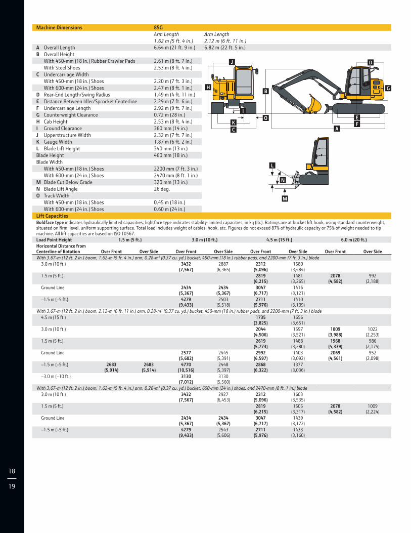
Machine Dimensions 85G
Arm Length
1.62 m (5 ft. 4 in.)
Arm Length
2.12 m (6 ft. 11 in.)
A Overall Length 6.64 m (21 ft. 9 in.) 6.82 m (22 ft. 5 in.)
B Overall Height
With 450-mm (18 in.) Rubber Crawler Pads 2.61 m (8 ft. 7 in.)
With Steel Shoes 2.53 m (8 ft. 4 in.)
C Undercarriage Width
With 450-mm (18 in.) Shoes 2.20 m (7 ft. 3 in.)
With 600-mm (24 in.) Shoes 2.47 m (8 ft. 1 in.)
D Rear-End Length/Swing Radius 1.49 m (4 ft. 11 in.)
E Distance Between Idler/Sprocket Centerline 2.29 m (7 ft. 6 in.)
F Undercarriage Length 2.92 m (9 ft. 7 in.)
G Counterweight Clearance 0.72 m (28 in.)
H Cab Height 2.53 m (8 ft. 4 in.)
I Ground Clearance 360 mm (14 in.)
J Upperstructure Width 2.32 m (7 ft. 7 in.)
K Gauge Width 1.87 m (6 ft. 2 in.)
L Blade Lift Height 340 mm (13 in.)
Blade Height 460 mm (18 in.)
Blade Width
With 450-mm (18 in.) Shoes 2200 mm (7 ft. 3 in.)
With 600-mm (24 in.) Shoes 2470 mm (8 ft. 1 in.)
M Blade Cut Below Grade 320 mm (13 in.)
N Blade Lift Angle 26 deg.
O Track Width
With 450-mm (18 in.) Shoes 0.45 m (18 in.)
With 600-mm (24 in.) Shoes 0.60 m (24 in.)
Lift CapacitiesBoldface type indicates hydraulically limited capacities; lightface type indicates stability-limited capacities, in kg (lb.). Ratings are at bucket lift hook, using standard counterweight, situated on Ɵrm, level, uniform supporting surface. Total load includes weight of cables, hook, etc. Figures do not exceed 87% of hydraulic capacity or 75% of weight needed to tip machine. All lift capacities are based on ISO 10567.
Load Point Height 1.5 m (5 ft.) 3.0 m (10 ft.) 4.5 m (15 ft.) 6.0 m (20 ft.)
Horizontal Distance from Centerline of Rotation
Over Front
Over Side
Over Front
Over Side
Over Front
Over Side
Over Front
Over Side
With 3.67-m (12 ft. 2 in.) boom, 1.62-m (5 ft. 4 in.) arm, 0.28-m3 (0.37 cu. yd.) bucket, 450-mm (18 in.) rubber pads, and 2200-mm (7 ft. 3 in.) blade
3.0 m (10 ft.) 3432 (7,567)
2887 (6,365)
2312 (5,096)
1580 (3,484)
1.5 m (5 ft.) 2819 (6,215)
1481 (3,265)
2078 (4,582)
992 (2,188)
Ground Line 2434 (5,367)
2434 (5,367)
3047 (6,717)
1416 (3,121)
–1.5 m (–5 ft.) 4279 (9,433)
2503 (5,518)
2711 (5,976)
1410 (3,109)
With 3.67-m (12 ft. 2 in.) boom, 2.12-m (6 ft. 11 in.) arm, 0.28-m3 (0.37 cu. yd.) bucket, 450-mm (18 in.) rubber pads, and 2200-mm (7 ft. 3 in.) blade
4.5 m (15 ft.) 1735 (3,825)
1656 (3,651)
3.0 m (10 ft.) 2044 (4,506)
1597 (3,521)
1809 (3,988)
1022 (2,253)
1.5 m (5 ft.) 2619 (5,773)
1488 (3,280)
1968 (4,339)
986 (2,174)
Ground Line 2577 (5,682)
2445 (5,391)
2992 (6,597)
1403 (3,092)
2069 (4,561)
952 (2,098)
–1.5 m (–5 ft.) 2683 (5,914)
2683 (5,914)
4770 (10,516)
2448 (5,397)
2868 (6,322)
1377 (3,036)
–3.0 m (–10 ft.) 3130 (7,012)
3130 (5,560)
With 3.67-m (12 ft. 2 in.) boom, 1.62-m (5 ft. 4 in.) arm, 0.28-m3 (0.37 cu. yd.) bucket, 600-mm (24 in.) shoes, and 2470-mm (8 ft. 1 in.) blade
3.0 m (10 ft.) 3432 (7,567)
2927 (6,453)
2312 (5,096)
1603 (3,535)
1.5 m (5 ft.) 2819 (6,215)
1505 (3,317)
2078 (4,582)
1009 (2,224)
Ground Line 2434 (5,367)
2434 (5,367)
3047 (6,717)
1439 (3,172)
–1.5 m (–5 ft.) 4279 (9,433)
2543 (5,606)
2711 (5,976)
1433 (3,160)
J
H
O
I
K
C
B
D
G
E
FA
L
M
N
Lift Capacities (continued) 85GBoldface type indicates hydraulically limited capacities; lightface type indicates stability-limited capacities, in kg (lb.). Ratings are at bucket lift hook, using standard counterweight, situated on Ɵrm, level, uniform supporting surface. Total load includes weight of cables, hook, etc. Figures do not exceed 87% of hydraulic capacity or 75% of weight needed to tip machine. All lift capacities are based on ISO 10567.
Load Point Height 1.5 m (5 ft.) 3.0 m (10 ft.) 4.5 m (15 ft.) 6.0 m (20 ft.)
Horizontal Distance from Centerline of Rotation
Over Front
Over Side
Over Front
Over Side
Over Front
Over Side
Over Front
Over Side
With 3.67-m (12 ft. 2 in.) boom, 2.12-m (6 ft. 11 in.) arm, 0.28-m3 (0.37 cu. yd.) bucket, 600-mm (24 in.) shoes, and 2470-mm (8 ft. 1 in.) blade
4.5 m (15 ft.) 1735 (3,825)
1679 (3,702)
3.0 m (10 ft.) 2044 (4,506)
1620 (3,572)
1809 (3,988)
1038 (2,289)
1.5 m (5 ft.) 2619 (5,773)
1511 (3,332)
1968 (4,339)
1002 (2,210)
Ground Line 2577 (5,682)
2485 (5,479)
2992 (6,597)
1426 (3,143)
2069 (4,561)
968 (2,134)
–1.5 m (–5 ft.) 2683 (5,914)
2683 (5,914)
4770 (10,516)
2488 (5,485)
2868 (6,322)
1400 (3,087)
–3.0 m (–10 ft.) 3130 (7,012)
3130 (5,647)
With 3.67-m (12 ft. 2 in.) boom, 2.12-m (6 ft. 11 in.) arm, less bucket, 450-mm (18 in.) continuous rubber belt, and 2200-mm (7 ft. 3 in.) blade
4.5 m (15 ft.) 1728 (3,810)
1579 (3,480)
3.0 m (10 ft.) 2050 (4,520)
1520 (3,350)
1805 (3,980)
971 (2,140)
1.5 m (5 ft.) 2626 (5,790)
1411 (3,110)
1969 (4,340)
934 (2,060)
Ground Line 2595 (5,720)
2309 (5,090)
2994 (6,600)
1329 (2,930)
2068 (4,560)
903 (1,990)
–1.5 m (–5 ft.) 2708 (5,970)
2708 (5,970)
4758 (10,490)
2309 (5,090)
2862 (6,310)
1306 (2,880)
–3.0 m (–10 ft.) 3139 (6,920)
2386 (5,260)
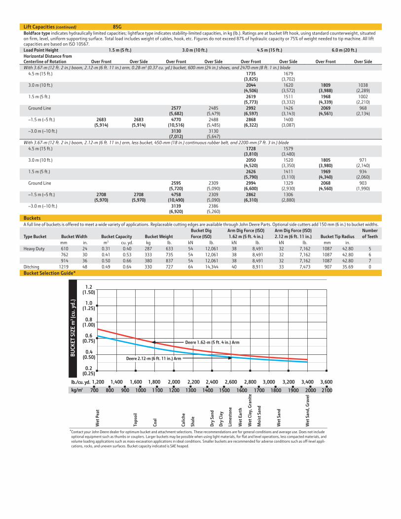
BucketsA full line of buckets is offered to meet a wide variety of applications. Replaceable cutting edges are available through John Deere Parts. Optional side cutters add 150 mm (6 in.) to bucket widths.
Type Bucket
Bucket Width
Bucket Capacity
Bucket Weight
Bucket Dig
Force (ISO)
Arm Dig Force (ISO)
1.62 m (5 ft. 4 in.)
Arm Dig Force (ISO)
2.12 m (6 ft. 11 in.)
Bucket Tip Radius
Number
of Teeth
mm in. m3 cu. yd. kg lb. kN lb. kN lb. kN lb. mm in.
Heavy Duty 610 24 0.31 0.40 287 633 54 12,061 38 8,491 32 7,162 1087 42.80 5
762 30 0.41 0.53 333 735 54 12,061 38 8,491 32 7,162 1087 42.80 6
914 36 0.50 0.66 380 837 54 12,061 38 8,491 32 7,162 1087 42.80 7
Ditching 1219 48 0.49 0.64 330 727 64 14,344 40 8,911 33 7,473 907 35.69 0
Bucket Selection Guide*
1.0(1.25)
0.6(0.75)
2,000 2,200 2,600 3,200lb./cu. yd.
kg/m3
BU
CK
ET
SIZ
E m
(cu
. yd
.)3
1,600 3,400
0.2(0.25)
0.4(0.50)
0.8(1.00)
1.2(1.50)
1,200 1,400 1,800 2,400 2,800 3,000 3,600
Wet
Pea
t
Top
soil
Co
al
Cal
ich
e
Shal
e
Dry
San
d
Dry
Cla
y
Lim
esto
ne
Wet
Ear
th
Wet
Cla
y, G
ran
ite
Mo
ist
San
d
Wet
San
d
Wet
San
d, G
rave
l
1300
Contact your John Deere dealer for optimum bucket and attachment selections. These recommendations are for general conditions and average use. Does not includeoptional equipment such as thumbs or couplers. Larger buckets may be possible when using light materials, for flat and level operations, less compacted materials, andvolume loading applications such as mass-excavation applications in ideal conditions. Smaller buckets are recommended for adverse conditions such as off-level appli-cations, rocks, and uneven surfaces. Bucket capacity indicated is SAE heaped.
*
700 800 900 1000 1100 1200 20001400 1500 1600 1700 1800 1900 2100
Deere 1.62-m (5 ft. 4 in.) Arm
Deere 2.12-m (6 ft. 11 in.) Arm
www.JohnDeere.com
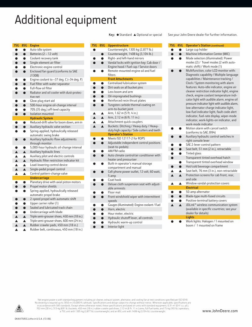
Key: ● Standard ▲ Optional or special See your John Deere dealer for further information.
Additional equipment
DKAX7585G Litho in U.S.A. (13-06)
Net engine power is with standard equipment including air cleaner, exhaust system, alternator, and cooling fan at test conditions speciƟed per ISO 9249. No derating is required up to 3050-m (10,000 ft.) altitude. SpeciƟcations and design subject to change without notice. Wherever applicable, speciƟcations are
in accordance with SAE standards. Except where otherwise noted, these speciƟcations are based on units with standard equipment; 0.31-m3 (0.41 cu. yd.), 762-mm (30 in.), 313-kg (691 lb.) buckets; 450-mm (18 in.) rubber crawler pad shoes; 2.12-m (6 ft. 11 in.) arms; full fuel tanks; and 75-kg (165 lb.) operators;
a 75G unit with 1305-kg (2,877 lb.) counterweight; and an 85G unit with 1408-kg (3,104 lb.) counterweight.
75G 85G Engine
● ● Auto-idle system
● ● Batteries (2 – 12 volt)
● ● Coolant recovery tank
● ● Single-element air Ɵlter
● ● Electronic engine control
● ● Enclosed fan guard (conforms to SAE
J1308)
● ● Engine coolant to –37 deg. C (–34 deg. F)
● ● Fuel Ɵlter with water separator
● ● Full-Ơow oil Ɵlter
● ● Radiator and oil cooler with dust-protec-
tive net
● ● Glow-plug start aid
● ● 500-hour engine oil-change interval
● ● 70% (35 deg.) off-level capacity
● ● Isolation mounted
Hydraulic System
● ● Reduced-drift valve for boom down, arm in
● ● Auxiliary hydraulic valve section
● ● Spring-applied, hydraulically released
automatic swing brake
● ● Auxiliary hydraulic-Ơow adjustments
through monitor
● ● 5,000-hour hydraulic oil-change interval
▲ ▲ Auxiliary hydraulic lines
▲ ▲ Auxiliary pilot and electric controls
▲ ▲ Hydraulic Ɵlter restriction indicator kit
▲ ▲ Load-lowering control device
▲ ▲ Single-pedal propel control
▲ ▲ Control pattern-change valve
Undercarriage
● ● Planetary drive with axial piston motors
● ● Propel motor shields
● ● Spring-applied, hydraulically released
automatic propel brake
● ● 2-speed propel with automatic shift
● ● Upper carrier roller (1)
● ● Sealed and lubricated track chain
● ● Undercarriage with blade
▲ ▲ Triple semi-grouser shoes, 450 mm (18 in.)
▲ ▲ Triple semi-grouser shoes, 600 mm (24 in.)
▲ ▲ Rubber crawler pads, 450 mm (18 in.)
▲ ▲ Rubber belt, continuous, 450 mm (18 in.)
75G 85G Upperstructure
● Counterweight, 1305 kg (2,877 lb.)
● Counterweight, 1408 kg (3,104 lb.)
● ● Right- and left-hand mirrors
● ● Vandal locks with ignition key: Cab door /
Engine hood / Fuel cap / Service doors
● ● Remote-mounted engine oil and fuel
Ɵlters
Front Attachments
● ● Centralized lubrication system
● ● Dirt seals on all bucket pins
● ● Less boom and arm
● ● Oil-impregnated bushings
● ● Reinforced resin thrust plates
● ● Tungsten carbide thermal coating on
arm-to-bucket joint
▲ ▲ Arm, 1.62 m (5 ft. 4 in.)
▲ ▲ Arm, 2.12 m (6 ft. 11 in.)
▲ ▲ Attachment quick-couplers
▲ ▲ Buckets: Ditching / Heavy duty / Heavy-
duty high capacity / Side cutters and teeth
Operator’s Station
● ● Meets ISO 12117-2 for ROPS
● ● Adjustable independent control positions
(seat-to-pedals)
● ● AM/FM radio
● ● Auto climate control/air conditioner with
heater and pressurizer
● ● Built-in operator’s manual storage
compartment and manual
● ● Cell-phone power outlet, 12 volt, 60 watt,
5 amp
● ● Coat hook
● ● Deluxe cloth suspension seat with adjust-
able armrests
● ● Floor mat
● ● Front windshield wiper with intermittent
speeds
● ● Gauges (illuminated): Engine coolant / Fuel
● ● Horn, electric
● ● Hour meter, electric
● ● Hydraulic shutoff lever, all controls
● ● Hydraulic warm-up control
● ● Interior light
75G 85G Operator’s Station (continued)
● ● Large cup holder
● ● Machine Information Center (MIC)
● ● Mode selectors (illuminated): Power
modes (2) / Travel modes (2 with auto-
matic shift) / Work mode (1)
● ● Multifunction, color LCD monitor with:
Diagnostic capability / Multiple-language
capabilities / Maintenance tracking /
Clock / System monitoring with alarm
features: Auto-idle indicator, engine air
cleaner restriction indicator light, engine
check, engine coolant temperature indi-
cator light with audible alarm, engine oil
pressure indicator light with audible alarm,
low-alternator-charge indicator light,
low-fuel indicator light, fault-code alert
indicator, fuel-rate display, wiper-mode
indicator, work-lights-on indicator, and
work-mode indicator
● ● Motion alarm with cancel switch
(conforms to SAE J994)
● ● Auxiliary hydraulic control switches in
right console lever
● ● SAE 2-lever control pattern
● ● Seat belt, 51 mm (2 in.), retractable
● ● Tinted glass
● Transparent tinted overhead hatch
● Transparent tinted overhead window
● ● Hot/cold beverage compartment
▲ ▲ Seat belt, 76 mm (3 in.), non-retractable
▲ ▲ Protection screens for cab front, rear,
and side
▲ ▲ Window vandal-protection covers
Electrical
● ● 50-amp alternator
● ● Blade-type multi-fused circuits
● ● Positive-terminal battery covers
▲ ▲ JDLink™ wireless communication system
(available in speciƟc countries; see your
dealer for details)
Lights
● ● Work lights: Halogen / 1 mounted on
boom / 1 mounted on frame


![LYRECO - [Main] 사무용품의 모든 것, 리레코: … › medias › pdf › 2016___u_a__U...바디워시 200g x 1개 바세린 로션 120ml x 1개 럭스비누 85g x 2개 도브](https://img.pdfslide.us/doc/110x75/5f0fe7a17e708231d44677bc/lyreco-main-e-ee-ef-ee-a-medias-a-pdf-a-2016uau.jpg)