Embed Size (px)
Citation preview
© 2011 Alamo Group Inc. $0.00
75CBH
Published 11/11 Part No. 50069997
OPERATOR’S MANUAL
BUSH HOG®
2501 Griffin Ave.Selma, AL 36703334-874-2700www.bushhog.com
BACKHOE
This Operator's Manual is an integral part of the safe operation of this machine and must be maintained with the unit at all times. READ, UNDERSTAND, and FOLLOW the Safety and Operation Instructions contained in this manual before operating the equipment. C01-Cover

TO THE OWNER/OPERATOR/DEALER
All implements with moving parts are potentially hazardous. There is no substitute for a cautious, safe-minded operator who recognizes the potential hazards and follows reasonable safety practices. The manufacturer has designed this implement to be used with all its safety equipment properly attached to minimize the chance of accidents.
BEFORE YOU START! Read the safety messages on the implement and shown in your manual. Observe the rules of safety and common sense!
WARRANTY INFORMATION:
Read and understand the complete Warranty Statement found in this Manual. Fill out the Warranty Registration Form in full and return it to within 30 Days. Make certain the Serial Number of the Machine is recorded on the Warranty Card and on the Warranty Form that you retain. The use of “will-fit” parts will void your warranty and can cause catastrophic failure with possible injury or death.
LEA EL INSTRUCTIVOSi No Lee Ingles, Pida Ayuda a Alguien Que SiLo Lea Que Le Traduzca Las Medidas deSeguridad.

TABLE OF CONTENTS
SAFETY SECTION ............................................................................................................................... 1-1
General Safety Instructions and Practices .............................................................................. 1-2Connecting and Disconnecting Safety Instructions and Practices .......................................... 1-5Equipment Operation Safety Instructions and Practices ......................................................... 1-6Transporting Safety Instructions and Practices ..................................................................... 1-11Storage Safety Instructions and Practices ............................................................................. 1-13Maintenance Safety Instructions and Practices ..................................................................... 1-13Concluding Safety Instructions and Practices ....................................................................... 1-14Decal Location ....................................................................................................................... 1-15Decal Description .................................................................................................................. 1-17Federal Laws and Regulations .............................................................................................. 1-19
INTRODUCTION SECTION ................................................................................................................. 2-1
SPECIFICATIONS ................................................................................................................... 2-3
ASSEMBLY SECTION ......................................................................................................................... 3-1
INSTALLING PUMP KIT (Optional) ......................................................................................... 3-2INSTALLING THREE POINT ADAPTER (Option) .................................................................. 3-3MOUNTING BACKHOE TO TRACTOR .................................................................................. 3-4
OPERATION SECTION ....................................................................................................................... 3-1
PRE-OPERATION CHECKLIST .............................................................................................. 3-2OPERATING DIRECTIONS .................................................................................................... 3-2ENGINE SPEED ...................................................................................................................... 3-2CONTROLS ............................................................................................................................. 3-2BOOM/SWING ........................................................................................................................ 3-2CROWD/BUCKET ................................................................................................................... 3-2LEFT HAND STABILIZER ....................................................................................................... 3-3RIGHT HAND STABILIZER ..................................................................................................... 3-3OPERATING BACKHOE ......................................................................................................... 3-3FILLING BUCKET ................................................................................................................... 3-4DUMPING BUCKET ................................................................................................................ 3-4TRENCHING BETWEEN A BUILDING & OPEN EXCAVATORS ........................................... 3-4SIDE SLOPE EXCAVATING OR TRENCHING ...................................................................... 3-5MISCELLANEOUS .................................................................................................................. 3-6FINISHING STRAIGHT WALLS .............................................................................................. 3-6BACKFILLING ......................................................................................................................... 3-7SEAT ADJUSTMENT .............................................................................................................. 3-7MOUNTING AND DISMOUNTING BUCKETS ........................................................................ 3-7PLACING THE STABILIZERS ................................................................................................. 3-8SWING LOCK .......................................................................................................................... 3-8BOOM LOCK ........................................................................................................................... 3-8STABILIZER LOCK ................................................................................................................. 3-8TRANSPORTING THE BACKHOE ......................................................................................... 3-8REMOVAL FROM TRACTOR - STORAGE ............................................................................ 3-9
MAINTENANCE SECTION .................................................................................................................. 4-1
CYLINDER SERVICE .............................................................................................................. 4-2CYLINDER DISASSEMBLY .................................................................................................... 4-2CYLINDER ASSEMBLY .......................................................................................................... 4-2BEGINNING OF SEASON ...................................................................................................... 4-3HYDRAULIC HOSES .............................................................................................................. 4-3HYDRAULIC SYSTEM RESERVOIR ...................................................................................... 4-3

BUCKET TOOTH POINTS ...................................................................................................... 4-4TIGHTENING NUTS AND BOLTS .......................................................................................... 4-4LUBRICATION ........................................................................................................................ 4-4LUBRICATION CHART ........................................................................................................... 4-4HYDRAULIC TROUBLESHOOTING ....................................................................................... 4-5VALVE SERVICE .................................................................................................................... 4-7MAIN RELIEF REPLACEMENT .............................................................................................. 4-7SPOOL SEAL INSTALLATION ............................................................................................... 4-7TORQUE SETTINGS .............................................................................................................. 4-7PARTS LIST ............................................................................................................................ 4-9PROPER TORQUE FOR FASTENERS ................................................................................ 4-10

Safety Section 1-1
SAFETY SECTION
SAFETYS
AF
ET
Y
General Safety Instructions and PracticesA careful operator is the best operator. Safety is of primary importance to the manufacturer and should be tothe owner/operator. Most accidents can be avoided by being aware of your equipment, your surroundings, andobserving certain precautions. The first section of this manual includes a list of Safety Messages that, iffollowed, will help protect the operator and bystanders from injury or death. Read and understand these SafetyMessages before assembling, operating or servicing this Implement. This equipment should only be operatedby those persons who have read the manual, who are responsible and trained, and who know how to do soresponsibly.
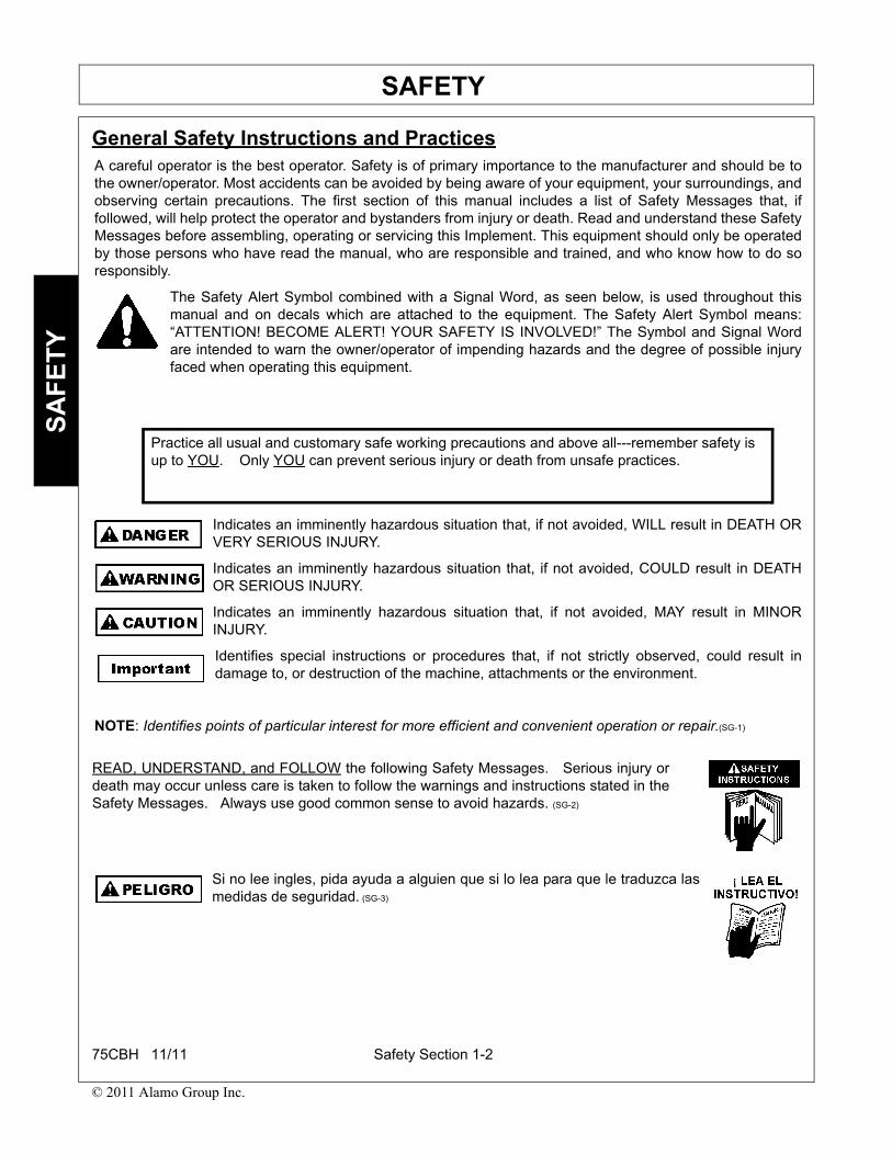
The Safety Alert Symbol combined with a Signal Word, as seen below, is used throughout thismanual and on decals which are attached to the equipment. The Safety Alert Symbol means:“ATTENTION! BECOME ALERT! YOUR SAFETY IS INVOLVED!” The Symbol and Signal Wordare intended to warn the owner/operator of impending hazards and the degree of possible injuryfaced when operating this equipment.
Indicates an imminently hazardous situation that, if not avoided, WILL result in DEATH ORVERY SERIOUS INJURY.
Indicates an imminently hazardous situation that, if not avoided, COULD result in DEATHOR SERIOUS INJURY.
Indicates an imminently hazardous situation that, if not avoided, MAY result in MINORINJURY.
Identifies special instructions or procedures that, if not strictly observed, could result indamage to, or destruction of the machine, attachments or the environment.
NOTE: Identifies points of particular interest for more efficient and convenient operation or repair.(SG-1)
Practice all usual and customary safe working precautions and above all---remember safety isup to YOU. Only YOU can prevent serious injury or death from unsafe practices.
READ, UNDERSTAND, and FOLLOW the following Safety Messages. Serious injury ordeath may occur unless care is taken to follow the warnings and instructions stated in theSafety Messages. Always use good common sense to avoid hazards. (SG-2)
Si no lee ingles, pida ayuda a alguien que si lo lea para que le traduzca lasmedidas de seguridad. (SG-3)
75CBH 11/11 Safety Section 1-2
© 2011 Alamo Group Inc.
SAFETYS
AF
ET
Y
Never operate the Tractor or Implement until you have read andcompletely understand this Manual, the Tractor Operator’s Manual, andeach of the Safety Messages found in the Manual or on the Tractor andImplement. Learn how to stop the tractor engine suddenly in anemergency. Never allow inexperienced or untrained personnel tooperate the Tractor or Implement without supervision. Make sure theoperator has fully read and understood the manuals prior to operation.(SG-4)
Never allow children to operate, ride on, or come close to the Tractor orImplement. Usually, 16-17 year-old children who are mature andresponsible can operate the implement with adult supervision, if theyhave read and understand the Operator’s Manuals, been trained inproper operation of the tractor and Implement, and are physically largeenough to reach and operate the controls easily. (SG-11)
Never allow children to play on or around Tractor or Implement. Children can slip or fall offthe Equipment and be injured or killed. Inadvertent contact with controls can cause theImplement to shift or fall crushing themselves or others. (SG-25)
DO NOT use drugs or alcohol immediately before or while operating theTractor and Implement. Drugs and alcohol will affect an operator’salertness and coordination and therefore affect the operator’s ability tooperate the equipment safely. Before operating the Tractor or Implement,an operator on prescription or over-the-counter medication must consulta medical professional regarding any side effects of the medication thatwould hinder their ability to operate the Equipment safely. NEVERknowingly allow anyone to operate this equipment when their alertness orcoordination is impaired. Serious injury or death to the operator or otherscould result if the operator is under the influence of drugs or alcohol. (SG-27)
Always read carefully and comply fully with the manufacturer’sinstructions when handling oil, solvents, cleansers, and any otherchemical agent. (SG-22)
Engine Exhaust, some of its constituents, and certain vehicle components contain or emitchemicals known to the state of California to cause cancer and birth defects or otherreproductive harm. (SG-30)
75CBH 11/11 Safety Section 1-3
© 2011 Alamo Group Inc.
SAFETYS
AF
ET
Y
Never run the Tractor engine in a closed building or without adequate ventilation. Theexhaust fumes can be hazardous to your health. (SG-23)
Battery posts, terminals and related accessories contain lead and lead compounds,chemicals known to the state of California to cause cancer, birth defects or otherreproductive harm. (SG-31)
The operator and all support personnel should wear hard hats, safetyshoes, safety glasses, and proper hearing protection at all times forprotection from injury including injury from items that may be thrown bythe equipment. (SG-16)
PROLONGED EXPOSURE TO LOUD NOISE MAY CAUSEPERMANENT HEARING LOSS! Tractors with or without an Implementattached can often be noisy enough to cause permanent hearing loss.We recommend that you always wear hearing protection if the noise inthe Operator’s position exceeds 80db. Noise over 85db over anextended period of time will cause severe hearing loss. Noise over 90dbadjacent to the Operator over an extended period of time will causepermanent or total hearing loss. NOTE: Hearing loss from loud noise[from tractors, chain saws, radios, and other such sources close to theear] is cumulative over a lifetime without hope of natural recovery. (SG-I7)
Repeated or substantial breathing of hazardous dusts, includingcrystalline silica, could cause fatal or serious respiratory disease includingsilicosis. Concrete, masonry, many types of rock, and various othermaterials contain silica sand. California lists respirable crystalline silica asa substance known to cause cancer. Operation of this equipment undercertain conditions may generate airborne dust particles that could containcrystalline silica. In those conditions, personal protective equipmentincluding an appropriate respirator must be used. If excessive dust isgenerated, a dust collection or suppression system should also be usedduring operation. (SG-41)
Use extreme caution when getting onto the Implement to perform repairs, maintenance andwhen removing accumulated material. Only stand on solid flat surfaces to ensure goodfooting. Use a ladder or raised stand to access high spots which cannot be reached fromground level. Slipping and falling can cause serious injury or death. (SG-33)
75CBH 11/11 Safety Section 1-4
© 2011 Alamo Group Inc.
SAFETYS
AF
ET
Y
Connecting and Disconnecting Safety Instructions and Practices
Use caution and wear protective gloves when handling sharp objects such as blades,knives, and other cutting edges. Be alert to worn component surfaces which have sharpedges. Sharp surfaces can inflict severe laceration injuries if proper hand protection is notworn. (SG-37)
For your protection while operating or servicing equipment, wear relatively tight and beltedclothing to avoid entanglement in moving parts. Tie up and protect long hair that couldbecome entangled in machinery. Remove all jewelry including necklaces, rings andwatches which can get caught in machinery or on corners or edges of the equipment.Serious injury can result from entanglement with the machinery. (SG-42)
Use extreme care when loading, carrying or handling any agriculturalfertilizers, chemicals or biological residue. Follow the manufacturer’shandling instructions and wear appropriate Personal ProtectiveEquipment including gloves, safety glasses and respirator when required.If you are using a tractor equipped with a cab, make sure the cab is ratedfor appropriate environmental exposure. Be safe and always wear properprotection. Short or long term exposure to certain chemicals andmaterials can result in serious injury or death. (SL-19)
Do not stand or allow bystander or coworkers between the Backhoe andthe tractor while installing or disconnecting the Backhoe from the tractor.Keep hands and body clear of the Backhoe and the Backhoe mounts.Serious injury or death can result from a person being crushed betweenthe tractor and Backhoe. (SBH-32)
Only mount the backhoe on a tractor that is listed on the mounting instructions. Nevermount on a tricycle steering front axle. Move the tractor front and rear wheels to the widestspacing and add the recommended rear tractor ballast to prevent tractor tip over. Keep thetractor tires properly inflated. Maintain at least 20% of the total Tractor and Backhoe weighton the front axle. Always wear your seatbelt and make sure the ROPS structure is fullydeployed to prevent serious injury or death from the tractor tipping over. (SBH-18)
Make sure the Backhoe is properly attached to the tractor and the retaining pins securelylock the Backhoe into position. Improper mounting of the Backhoe onto the tractor canresult in the Backhoe falling causing serious injury. (SBH-22)
Make sure all tractor and Backhoe guards are in place and properly functioning. (SBH-26)
75CBH 11/11 Safety Section 1-5
© 2011 Alamo Group Inc.
SAFETYS
AF
ET
Y
Equipment Operation Safety Instructions and Practices
Make sure the hydraulic quick disconnects are fully seated into the connections. Do not usethe Backhoe if the hydraulic connection is leaking. Leaking oil could allow the Backhoe tofall resulting in a serious crushing injury. (SBH-21)
Make sure all air is purged from the hydraulic system before using the Backhoe. Air in thesystem can cause the Backhoe to respond sluggishly or with unexpected movement. Theair can be purged from the cylinder lines by fully cycling the cylinders several times from thefully closed to fully open position. Sudden or unexpected movement or dropping of theBackhoe and attachment could result in serious injury. (SBH-29)
Never interfere with factory-set hydraulic calibrations. Any change in calibration couldcause a failure of the equipment and may result in injury. (SBH-13)
Backhoe mounting bolts and nuts must be kept tightened. Retighten the bolts and nuts afterthe first 10 minutes of operation, and every 8 hours after that. (SBH-39)
Do not lean over controls. Engage and disengage the boom and stabilizer transport locksand the swing lock pin with the engine off. Do not operate the backhoe control from outsideof the operator’s area. (SBH-40)
Do not use the backhoe hydraulic control levers as grab handles. Activation of the controllevers can cause unexpected movement of the boom, arm, bucket or stabilizers. Alwaysenter and exit the backhoe from the ground using the steps and grab handles. (SBH-41)
Operate the tractor only while seated in the tractor seat with the seatbelt fastened. Operatethe backhoe only while seated in the backhoe seat. (SBH-19)
Never allow children or other persons to ride on the Tractor or Implement.Falling off can result in serious injury or death. (SG-10)
Do not mount or dismount the Tractor while the tractor is moving. Mountthe Tractor only when the Tractor and all moving parts are completelystopped. (SG-12)
75CBH 11/11 Safety Section 1-6
© 2011 Alamo Group Inc.
SAFETYS
AF
ET
Y
Start tractor only when properly seated in the Tractor seat. Starting atractor in gear can result in injury or death. Read the Tractor operatorsmanual for proper starting instructions. (SG-13)
Operate this Equipment only with a Tractor equipped with an approved roll-over-protective system (ROPS). Always wear seat belts. Serious injury oreven death could result from falling off the tractor--particularly during a turnoverwhen the operator could be pinned under the ROPS. (SG-7)
Operate the Tractor and/or Implement controls only while properly seated in the Tractor seatwith the seat belt securely fastened around you. Inadvertent movement of the Tractor orImplement may cause serious injury or death. (SG-29)
Movement of the backhoe boom, stabilizers and attachment can create pinch points thatcan cause serious crushing injuries. Only operate the backhoe controls while seated in theoperator’s seat. Keep your hands, arms and legs inside the operator’s zone. Stop operatingthe backhoe if any bystanders or coworkers come within 25 feet of the backhoe. (SBH-42)
Keep bystanders 25 feet away from the tractor and backhoe whileoperating. The bystanders could enter the path of the tractor or itemscould fall from the backhoe resulting in serious injury to the bystander.Position a barricade perimeter around the work area. Stop operating thebackhoe if any person enters the work area. (SBH-14)
Prolonged operation may cause operator boredom and fatigue affecting safe operation.Take scheduled work breaks to help prevent these potentially impaired operatingconditions. Never operate the Implement and Tractor in a fatigued or bored mental statewhich impairs proper and safe operation. (SG-32)
Never dig with backhoe unless stabilizers are lowered and properly seated. Do not digunder stabilizers or tractor with backhoe. Soft ground or sandy soil could cause cave in andtractor rollover. (SBH-43)
75CBH 11/11 Safety Section 1-7
© 2011 Alamo Group Inc.
SAFETYS
AF
ET
Y
Operate the tractor and Backhoe only in conditions where you have clear visibility indaylight or with adequate artificial lighting. Never operate in darkness or foggy conditionswhere you cannot clearly see at least 100 feet in front and to the sides of the tractor. Makesure you can clearly see bystanders, ditches, steep slopes, drop-offs, overheadobstructions, power lines, and debris or obstruction in the travel path. If you are unable toclearly see these types of items discontinue operating. Contact with unseen vehicles,bystanders, obstructions, or drop-offs can cause serious injury. (SBH-31)
Do Not operate this equipment in areas where insects such as bees may attack you and/orcause you to lose control of the equipment. If you must enter in such areas, use a tractorwith an enclosed Cab and close the windows to prevent insects from entering. If a tractorcab is not available, wear suitable clothing including head, face, and hand protection toshield you from the insects. Attacking insects can cause you to lose control of the tractor,which can result in serious injury or death to you or bystanders. Never dismount a movingtractor. (SG-40)
In case of mechanical difficulty during operation, place the transmission in the parkposition, set the parking brake, shut down all power, including the PTO and the engine andremove the key. Wait until all rotating motion has stopped before dismounting. (SG-39)
If the Backhoe valve controls fail to function properly discontinue use of the tractor andBackhoe until the controls are properly repaired. Sudden or unexpected movement ordropping of the Backhoe and attachment could result in serious injury. (SBH-28)
Never leave the Implement and Power Unit unattended while the Implement is in the raisedposition. Accidental operation of a lifting lever or a hydraulic failure may cause theimplement to suddenly fall causing serious injury or possible death to anyone who mightinadvertently be under the Implement. Lower the implement carefully to the ground. Do notput hands or feet under lifted components. (SPU-3)
Do not operate this Equipment with hydraulic oil or fuel leaking. Oiland fuel are explosive and their presence could present a hazard. Donot check for leaks with your hand! High-pressure oil streams frombreaks in the line could penetrate the skin and cause tissue damageincluding gangrene. To check for a hose leak, SHUT the unit ENGINEOFF and remove all hydraulic pressure. Wear oil impenetrable gloves,safety glasses and use Cardboard to check for evidence of oil leaks. Ifyou suspect a leak, REMOVE the HOSE and have it tested at a Dealer.If oil does penetrate the skin, have the injury treated immediately by aphysician knowledgeable and skilled in this procedure. (SG-15)
75CBH 11/11 Safety Section 1-8
© 2011 Alamo Group Inc.
SAFETYS
AF
ET
Y
Never walk or work under any raised boom or bucket. The Boom could fall and causeserious bodily injury or death. Always lower the boom and bucket flat on the ground orsupport the Boom and bucket on safety stands. Unload all hydraulic actuators prior toperforming any maintenance. To do this, set the bucket on the ground then kill the tractorengine. Push and pull the control levers in and out several times to remove pressure. Donot work under raised Boom or Bucket unless components are securely blocked up toprevent inadvertent dropping. (SBH-7)
Avoid contact with hot surfaces including hydraulic oil tanks, pumps, motors, valves andhose connections. Relieve hydraulic pressure before performing maintenance or repairs.Use gloves and eye protection when servicing hot components. Contact with a hot surfaceor fluid can cause serious injury from burns or scalding. (SG-34)
Avoid contact with hot surfaces of the engine or muffler. Use gloves and eye protectionwhen servicing hot components. Contact with a hot surface or fluid can cause serious injuryfrom burns or scalding. (SG-38)
Be sure you have adequate knowledge of the property you will be working on. Take time tomake yourself aware of any area underground lines or cables. Contact with buried lines orcable could result in serious injury or death. If in doubt about buried utility lines call 811before digging or 1-800-258-0808. (SBH-6)
Do not let the Backhoe or attachment contact electrical powerlines. Contact with electrical power lines can result in seriousinjury or electrocution. If the backhoe attachment contacts apower line remain in the tractor seat until the power has beenshut off. Stepping off the tractor can permit electrical currentto pass through the body resulting in electrocution. (SBH-17)
The Boom is designed only to position and operate the Bucket which is attached to it. Neverattempt to lift, pull, or push other solid objects with the boom or bucket. Serious injury couldresult from a structural failure when the Boom is used for purposes other than those forwhich it was designed. (SBH-9)
Never attach pulling devices to the rear of the backhoe. The unit could tip rearwardscausing serious injury or even death. (SBH-10)
Do not use Backhoe as a jack to raise the tractor tires off the ground. The Backhoe couldfail causing the tractor and Backhoe to fall to the ground resulting in serious injury. (SBH-24)
75CBH 11/11 Safety Section 1-9
© 2011 Alamo Group Inc.
SAFETYS
AF
ET
Y
Do not work from the backhoe or attachments. Do now allow anyriders on the backhoe, tractor or attachments. Falling off couldresult in serious injury. (SBH-34)
Use extreme care when digging, transporting or dumping loads that impair or partially blockthe operator’s line of sight. Know where you are traveling. Make sure no bystanders are inthe area of travel. If a bystander assists in providing guidance, make sure they are not in thepath of travel. Keep all bystanders 25 feet away from travel path. (SBH-35)
Do not raise the Backhoe on a hillside. Do not transportacross a slope with a raised Backhoe. When theBackhoe is raised, the center of gravity of the tractor andBackhoe is raised increasing the potential for the tractorto tip over. Tractor wheel contact with any wash out, dropoff or the ground obstruction with a raised Backhoecould result in the tractor tipping over and causingserious bodily injury. (SBH-20)
When the bucket is swung to the side of the tractor, it exerts a movement on the tractorcausing the tractor to rock from side to side. Make sure the stabilizers are lowered to theground and stabilize the tractor before swinging the boom.Extreme care should be takenwhen operating on slopes. Bodily Harm or Death could result from tractor’s tipping over.(SBH-1)
Avoid full reach and swinging a loaded bucket to the down hill side when operating onslopes. (SBH-2)
Digging with the arm may pull the compact tractor backward. Do not dig too much material atone time. (SBH-44)
Use extreme care when piling material above 6 feet high. Material couldshift and fall onto the operator or bystanders. The material could crush orsuffocate the operator or bystander resulting in serious injury or death.(SBH-45)
Always lower bucket and stabilizer feet to the ground, and shut off the engine beforedismounting from the unit. (SBH-11)
75CBH 11/11 Safety Section 1-10
© 2011 Alamo Group Inc.
SAFETYS
AF
ET
Y
Transporting Safety Instructions and Practices
BEFORE leaving the tractor seat lower the implement, set the parkingbrake and/or set the tractor transmission in parking gear, disengage thePTO, stop the engine, remove the key, and wait for all moving parts tostop. Place the tractor shift lever into a low range or parking gear toprevent the tractor from rolling. Never dismount a Tractor that is movingor while the engine is running. Operate the Tractor controls from thetractor seat only. (SG-9)
Transport only at speeds where you can maintain control of theequipment. Serious accidents and injuries can result from operating thisequipment at high speeds. Understand the Tractor and Implement and
how it handles before transporting on streets and highways. Make sure the Tractor steeringand brakes are in good condition and operate properly.
Before transporting the Tractor and Implement, determine the proper transport speeds foryou and the equipment. Make sure you abide by the following rules:
Test the tractor at a slow speed and increase the speed slowly. Apply the Brakes smoothlyto determine the stopping characteristics of the Tractor and Implement. As you increasethe speed of the Tractor the stopping distance increases. Determine the maximumtransport speed not to exceed 20 mph (30 kph) for transporting this equipment.
Test the equipment at a slow speed in turns. Increase the speed through the turn only afteryou determine that the equipment can be operated at a higher speed. Use extreme careand reduce your speed when turning sharply to prevent the tractor and implement fromturning over. Determine the maximum turning speed for you and this equipment beforeoperating on roads or uneven ground.
Only transport the Tractor and Implement at the speeds which allow you to properly controlthe equipment.
Be aware of the operating conditions. Do not operate the Tractor with weak or faulty brakesor worn tires. When operating down a hill or on wet or rain slick roads, the braking distanceincreases: use extreme care and reduce your speed. When operating in traffic always usethe Tractor’s flashing warning lights and reduce your speed. Be aware of traffic around youand watch out for the other guy. (SG-19)
Be particularly careful when transporting the Implement with the Tractor. Turn curves or goup hills only at a low speed and using a gradual steering angle. Rear mounted implementsmove the center of gravity to the rear and remove weight from the front wheels. Make
certain, by adding front ballast, that at least 20% of the tractor’s weight is on the front wheels to prevent rearingup, loss of steering control or Tractor tip-over. Slow down on rough or uneven surfaces to prevent loss ofsteering control which could result in property damage or possible injury. Dropping implement in transport cancause serious damage to the tractor and/or Implement and possibly cause the operator or others to be injuredor killed. (SBH-38)
75CBH 11/11 Safety Section 1-11
© 2011 Alamo Group Inc.
SAFETYS
AF
ET
Y
Do not drive near the edge of a ditch or excavation. The soil could giveway resulting inloss of control or rollover. (SBH-46)
Use extra care when turning or stopping. Allow for increased length and weight of addedbackhoe. The backhoe adds five to six feet of length in rear of the tractor and significantweight. Allow extra distance when stopping or turning. Do not allow backhoe or attachmentto contact solid objects. (SBH-16)
Be careful when operating or transporting this equipment to prevent the Implement fromrunning into or striking sign posts, guard rails, concrete abutments or other solid objects.Such an impact could cause the Implement and Tractor to pivot violently resulting in loss ofsteering control, serious injury, or even death. Never allow the Implement to contactobstacles. (SBH-48)
Lower the Backhoe to the bed of the truck or trailer whentransporting the tractor and Backhoe with a truck. Measureto ensure the transport height does not exceed the legallimits. Contact with overhead obstructions or power lines cancause property damage or serious injury. (SBH-30)
Make certain that the “Slow Moving Vehicle” (SMV) sign is installed insuch a way as to be clearly visible and legible. When transporting theEquipment use the Tractor flashing warning lights and follow all localtraffic regulations. (SG-6)
Engage boom swing and lift pins. Lock both stabilizers in the raised position. If the backhoeattachment, such as a bucket, were to drop suddenly and hit the ground while transporting,the tractor could stop or swing to the side. Immediately resulting in the operator hitting thesteering wheel or flying out of the operator’s seat. Serious injury could result. (SBH-15)
Your driving vision may be reduced or impaired by the tractor, cab, or implement. Beforedriving on public roadways identify any limited vision areas, and make adjustments to youroperating position, mirrors, and the implement transport position so that you can clearlysee the area where you will be traveling, and any traffic that may approach you. Failure tomaintain adequate vision of the public roadway and traffic can result in serious injury oreven death. (STI-10)
Carry the Backhoe and attachment low when transporting toreduce the potential of the tractor tipping over. Transport onslopes only at slow speeds and use gradual turning angles.Tractor wheel contact with any wash out, drop off or groundobstruction with a raised Backhoe could result in the tractortipping over and causing serious injury. (SBH-36)
75CBH 11/11 Safety Section 1-12
© 2011 Alamo Group Inc.
SAFETYS
AF
ET
Y
Storage Safety Instructions and Practices
Maintenance Safety Instructions and Practices
Always look behind you before backing up. Make sure youare looking in the direction of travel. A bystander could walkbehind the tractor. Running into a bystander can result inserious injury or death. (SBH-27)
Always lower legs and bucket to the ground and engage the swing lock when the Backhoeis not in use. (SBH-8)
Always store in a stable position with the swing lock and lift ram strap engaged. (SBH-12)
Do not remove the attachment from the Backhoe when the Backhoe is disconnected fromthe tractor. The attachment stabilizes the Backhoe. If the attachment is removed, theBackhoe will fall and could result in serious injury. (SBH-25
Never crawl under or allow children to play around or on a Backhoe that is disconnectedfrom the tractor. The Backhoe could fall crushing a person resulting in serious injury ordeath. (SBH-33)
Perform service, repairs and lubrication according to the maintenance section. Ensure theunit is properly lubricated as specified in the lubrication schedule and all bolts and nuts areproperly torqued. Failure to properly service, repair and maintain this Implement in goodoperating condition could cause component failure and possible serious injury or evendeath. (SG-35)
Relieve hydraulic pressure prior to doing any maintenance or repairwork on the Implement. Place the Implement on the ground orsecurely blocked up, disengage the PTO, and turn off the tractorengine. Push and pull the Remote Cylinder lever in and out severaltimes. Disconnect and remove the Implement hydraulic hoses fromthe tractor prior to starting any maintenance or repair work. (STL-17)
Never attempt to lubricate, adjust, or remove material from the Implement while it is inmotion or while tractor engine is running. (SG-20)
75CBH 11/11 Safety Section 1-13
© 2011 Alamo Group Inc.
SAFETYS
AF
ET
Y
Concluding Safety Instructions and Practices
Periodically inspect all moving parts for wear and replace whennecessary with authorized service parts. Look for loose fasteners, wornor broken parts, and leaky or loose fittings. Make sure all pins havecotter pins and washers. Serious injury may occur from not maintainingthis machine in good working order. (SG-21)
Always maintain the safety signs in good readable condition. If the safety signs are missing,damaged, or unreadable, obtain and install replacement safety signs immediately. (SG-5)
Do Not fill fuel tank while engine is running. Refuel only after engine has cooled down. Iffuel is spilled, move machine away from the area of the spill and avoid creating any sourceof ignition until the fuel has evaporated. (SBH-49)
Do not modify or alter this Implement. Do not permit anyone to modify or alter thisImplement, any of its components or any Implement function. (SG-8)
Never work under the Implement, the framework, or any lifted componentunless the Implement is securely supported or blocked up to preventsudden or inadvertent falling which could cause serious injury or evendeath. (SBH-47)
PARTS INFORMATIONBush Hog products are designed utilizing specifically matched system components to ensure optimumequipment performance. These parts are made and tested to Bush Hog specifications. Non-genuine "will fit"parts do not consistently meet these specifications. The use of “will fit” parts may reduce equipmentperformance, void warranties, and present a safety hazard. Use genuine Bush Hog parts for economy andsafety. (SPBH-2)
SEE YOUR BUSH HOG DEALER
In addition to the design and configuration of this Implement, including Safety Signs and Safety Equipment,hazard control and accident prevention are dependent upon the awareness, concern, prudence, and propertraining of personnel involved in the operation, transport, maintenance, and storage of the machine. Referalso to Safety Messages and operation instruction in each of the appropriate sections of the Tractor andEquipment Manuals. Pay close attention to the Safety Signs affixed to the Tractor and Equipment. (SG-18)
75CBH 11/11 Safety Section 1-14
© 2011 Alamo Group Inc.
SAFETYS
AF
ET
Y
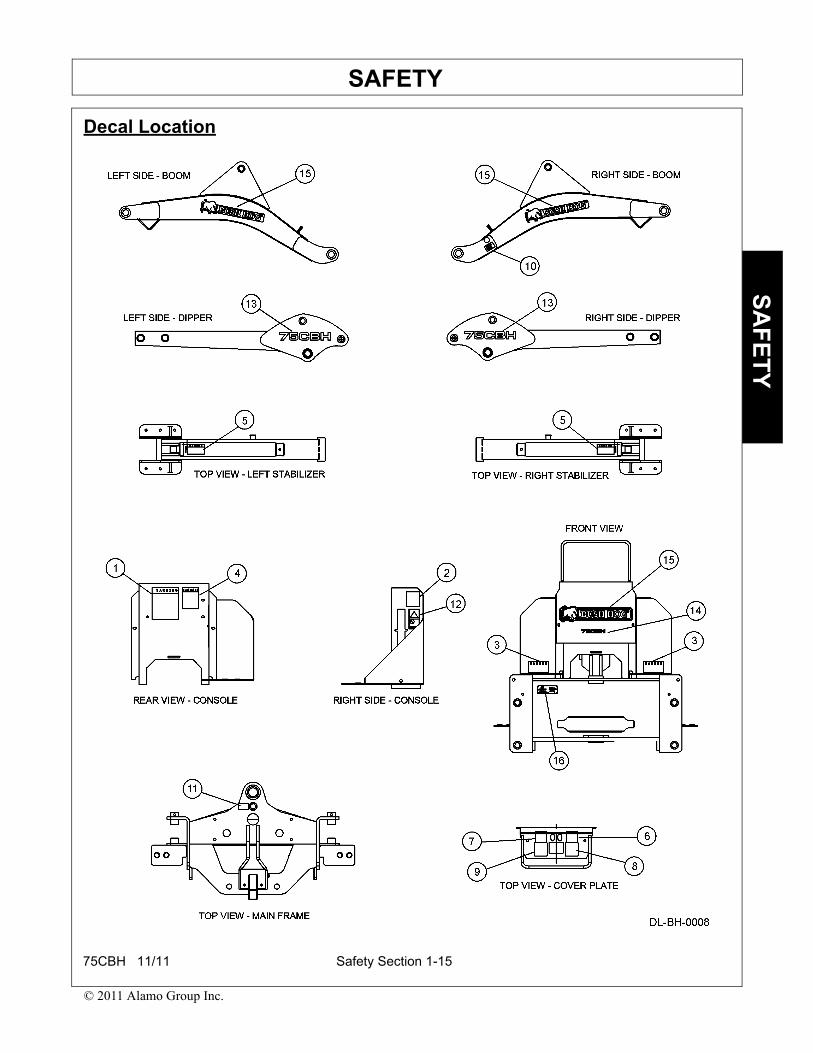
Decal Location
75CBH 11/11 Safety Section 1-15
© 2011 Alamo Group Inc.

SAFETYS
AF
ET
Y
ITEM PART NO. QTY LEVEL DESCRIPTION
1. 45970 1 WARNING To Prevent Bodily Injury
2. 44907 1 WARNING To Prevent Instability
3. 44895 2 DANGER Crushing Hazard
4. 44896 1 WARNING To Prevent Bodily Injury
5. 44897 2 DANGER Crushing Hazard
6. 44898 1 OPERATION Boom Operation
7. 44899 1 OPERATION Dipperstick & Bucket Operation
8. 44900 1 OPERATION Left Side Stabilizer Position
9. 44901 1 OPERATION Right Side Stabilizer Position
10. 44908 1 OPERATION Boom Lock
11. 44909 1 OPERATION Swing Lock
12. 48280 1 INFORMATION Universal One Call
13. 50069981 2 NAME Model Name 75CBH (Big)
14. 50069982 1 NAME Model Name 75CBH (Small)
15. 50057411 3 LOGO Bush Hog Logo
16. 50069988 1 SER PLT Serial Number Plate
75CBH 11/11 Safety Section 1-16
© 2011 Alamo Group Inc.

SAFETYS
AF
ET
Y
Decal Description
9 -- 44901 8 -- 44900 11 -- 44909
10 -- 44908
13 -- 50069981
15 -- 50057411
7 -- 44899 6 -- 44898
14 -- 50069982
75CBH 11/11 Safety Section 1-17
© 2011 Alamo Group Inc.
SAFETYS
AF
ET
Y
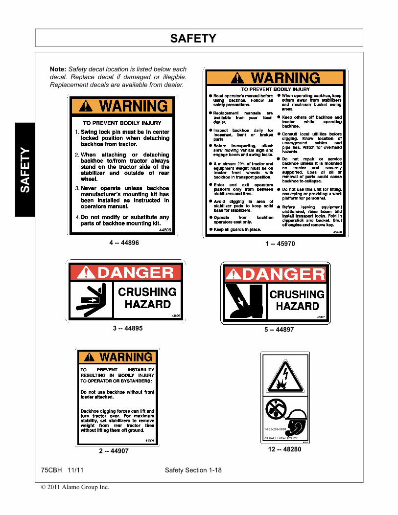
4 -- 44896 1 -- 45970
3 -- 44895 5 -- 44897
2 -- 44907 12 -- 48280
Note: Safety decal location is listed below eachdecal. Replace decal if damaged or illegible.Replacement decals are available from dealer.
75CBH 11/11 Safety Section 1-18
© 2011 Alamo Group Inc.

SAFETYS
AF
ET
Y
Federal Laws and Regulations
This section is intended to explain in broad terms the concept and effect of federal laws and regulations concerningemployer and employee equipment operators. This section is not intended as a legal interpretation of the law andshould not be considered as such.
Employer-Employee Operator Regulations
U.S. Public Law 91-596 (The Williams-Steiger Occupational and Health Act of 1970) OSHA
This Act Seeks:
“...to assure so far as possible every working man and woman in the nation safe and healthful workingconditions and to preserve our human resources...”
DUTIESSec. 5 (a) Each employer-
(1) shall furnish to each of his employees employment and a place of employment which are free fromrecognized hazards that are causing or are likely to cause death or serious physical harm to his employees;
(2) shall comply with occupational safety and health standards promulgated under this Act.
(b) Each employee shall comply with occupational safety and health standards and all rules, regulations andorders issued pursuant to this Act which are applicable to his own actions and conduct.
OSHA Training Requirements
Title 29, Code of Federal Regulations Part 1928.57(a)(6). www.osha.gov
Operator instructions. At the time of initial assignment and at least annually thereafter, the employer shallinstruct every employee who operates an agricultural tractor and implements in the safe operating practicesand servicing of equipment with which they are or will be involved, and of any other practices dictated by thework environment.
Keep all guards in place when the machine is in operation;
Permit no riders on equipment
Stop engine, disconnect the power source, and wait for all machine movement to stop before servicing,adjusting, cleaning or unclogging the equipment, except where the machine must be running to be properlyserviced or maintained, in which case the employer shall instruct employees as to all steps and procedureswhich are necessary to safely service or maintain the equipment.
Make sure everyone is clear of machinery before starting the engine, engaging power, or operating themachine.
Employer Responsibilities:
To ensure employee safety during Tractor and Implement operation, it is the employer’s responsibility to:
1. Train the employee in the proper and safe operation of the Tractor and Implement.
2. Require that the employee read and fully understand the Tractor and Implement Operator’s manual.
3. Permit only qualified and properly trained employees to operate the Tractor and Implement.
4. Maintain the Tractor and Implement in a safe operational condition and maintain all shields and guards on theequipment.
5. Ensure the Tractor is equipped with a functional ROPS and seat belt and require that the employee operatorsecurely fasten the safety belt and operate with the ROPS in the raised position at all times.
6. Forbid the employee operator to carry additional riders on the Tractor or Implement.
7. Provide the required tools to maintain the Tractor and Implement in a good safe working condition and provide thenecessary support devices to secure the equipment safely while performing repairs and service.
8. Require that the employee operator stop operation if bystanders or passersby come within 300 feet.
Child Labor Under 16 Years of Age
Some regulations specify that no one under the age of 16 may operate power machinery. It is your responsibility toknow what these regulations are in your own area or situation. (Refer to U.S. Dept. of Labor, Employment StandardAdministration, Wage & Home Division, Child Labor Bulletin #102.)
75CBH 11/11 Safety Section 1-19
© 2011 Alamo Group Inc.


Introduction Section 2-1
INTRODUCTION SECTION
INTRODUCTIONIN
TR
OD
UC
TIO
N
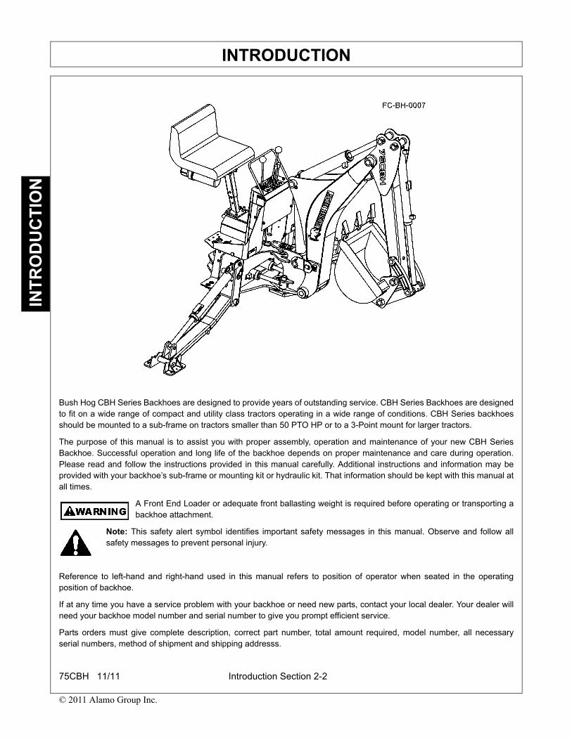
Bush Hog CBH Series Backhoes are designed to provide years of outstanding service. CBH Series Backhoes are designedto fit on a wide range of compact and utility class tractors operating in a wide range of conditions. CBH Series backhoesshould be mounted to a sub-frame on tractors smaller than 50 PTO HP or to a 3-Point mount for larger tractors.
The purpose of this manual is to assist you with proper assembly, operation and maintenance of your new CBH SeriesBackhoe. Successful operation and long life of the backhoe depends on proper maintenance and care during operation.Please read and follow the instructions provided in this manual carefully. Additional instructions and information may beprovided with your backhoe’s sub-frame or mounting kit or hydraulic kit. That information should be kept with this manual atall times.
A Front End Loader or adequate front ballasting weight is required before operating or transporting abackhoe attachment.
Note: This safety alert symbol identifies important safety messages in this manual. Observe and follow allsafety messages to prevent personal injury.
Reference to left-hand and right-hand used in this manual refers to position of operator when seated in the operatingposition of backhoe.
If at any time you have a service problem with your backhoe or need new parts, contact your local dealer. Your dealer willneed your backhoe model number and serial number to give you prompt efficient service.
Parts orders must give complete description, correct part number, total amount required, model number, all necessaryserial numbers, method of shipment and shipping addresss.
75CBH 11/11 Introduction Section 2-2
© 2011 Alamo Group Inc.

INTRODUCTIONIN
TR
OD
UC
TIO
N
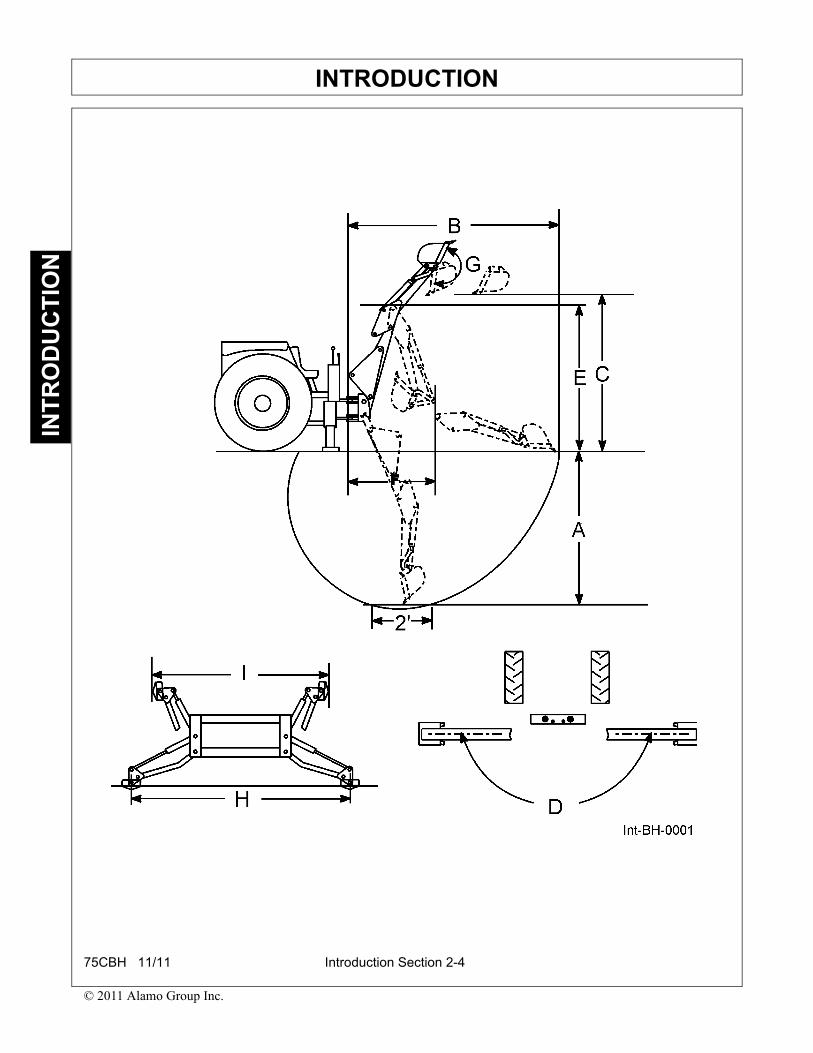
SPECIFICATIONSSpecifications may vary depending on tractor model, tire size and bucket used and are subject to change withoutnotification. Tractor must be equipped with ROPS and seat belt that will provide greater safety and installation of backhoesubframe.
GENERAL DATA
A. Digging Depth (two foot flat bottom) ...............................................85.25”B. Reach from center line of Swing Pivot............................................117.58”C. Loading Height (bucket at 60°) .......................................................69.88”D. Swing Arc .......................................................................................180°E. Transport Height (maximum) ..........................................................77.34”F. Transport Overhang........................................................................43.5”G. Bucket Rotation ..............................................................................180°H. Stabilizer Spread, down position.....................................................90”I. Stabilizer Spread, up position .........................................................53.75”J. Backhoe Weight..............................................................................965 lbsK. Shipping Weight (less bucket) ........................................................1014 lbs
BUCKET DATA
BUCKET WIDTH SAE STRUCK CAPACITY SAE HEAPED CAPACITY
9” 0.73 cu. ft. 0.87cu. ft.12” 1.01 cu. ft. 1.24 cu. ft.16” 1.38 cu. ft. 1.76 cu. ft.18” 1.56 cu. ft. 2.02 cu. ft.24” 2.11 cu. ft. 2.82 cu. ft.36” Grave 2.78 cu. ft. 4.0 cu. ft.36” Muck 2.78 cu. ft. 4.0 cu. ft
CYLINDER DATA
CYLINDER PISTON DIA. STROKE RETRACTED EXTENDED ROD DIA. LENGTH LENGTH
Boom 2.75” 16.75” 25.5” 42.25” 1.5”Dipperstick 3” 14.12” 23.06” 37.19” 1.5”Bucket 2” 19.25” 27” 46.25 1.375”Swing 2.25” 8.56” 16” 24.56” 1.13”Stabilizer 2.25” 14” 21” 35” 1.375”
75CBH 11/11 Introduction Section 2-3
© 2011 Alamo Group Inc.
INTRODUCTIONIN
TR
OD
UC
TIO
N
75CBH 11/11 Introduction Section 2-4
© 2011 Alamo Group Inc.

Assembly Section 3-1
ASSEMBLY SECTION
ASSEMBLYA
SS
EM
BLY
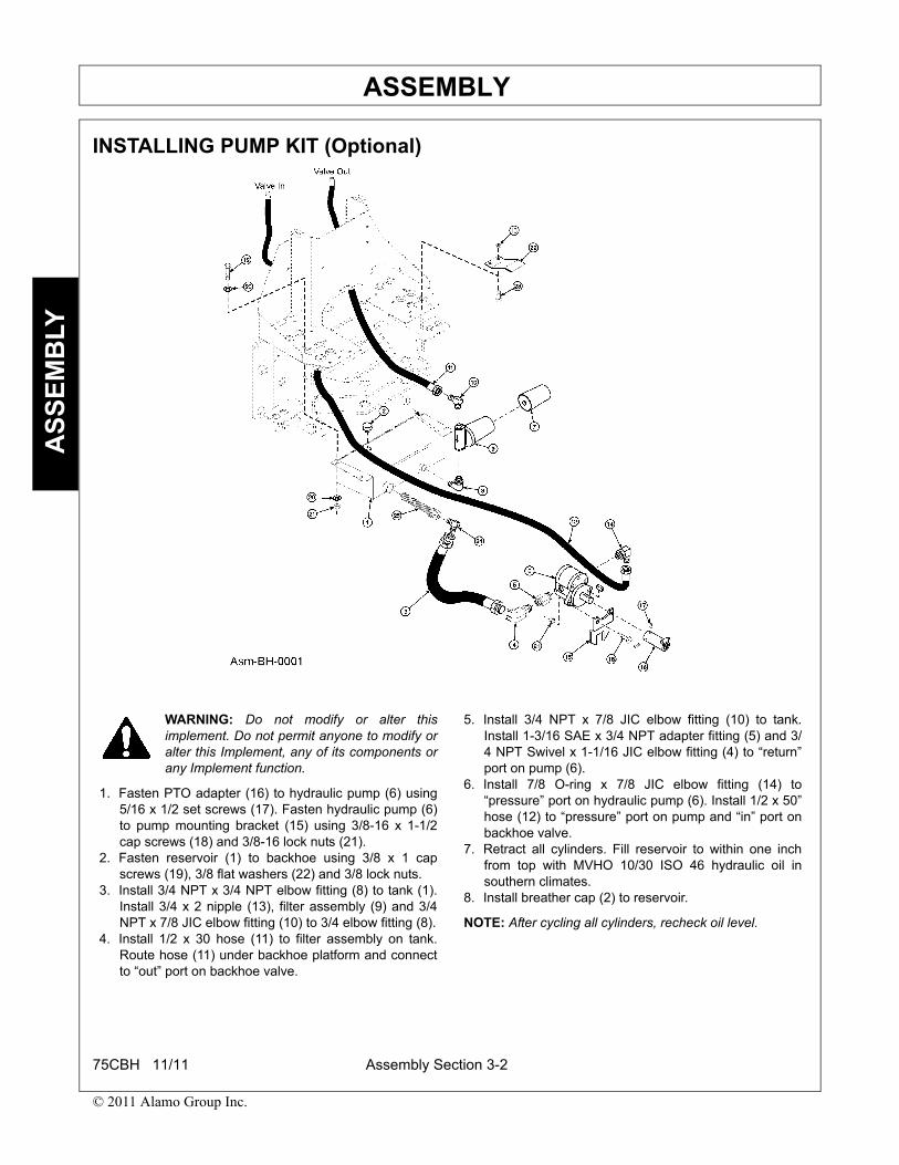
INSTALLING PUMP KIT (Optional)
WARNING: Do not modify or alter thisimplement. Do not permit anyone to modify oralter this Implement, any of its components orany Implement function.
1. Fasten PTO adapter (16) to hydraulic pump (6) using5/16 x 1/2 set screws (17). Fasten hydraulic pump (6)to pump mounting bracket (15) using 3/8-16 x 1-1/2cap screws (18) and 3/8-16 lock nuts (21).
2. Fasten reservoir (1) to backhoe using 3/8 x 1 capscrews (19), 3/8 flat washers (22) and 3/8 lock nuts.
3. Install 3/4 NPT x 3/4 NPT elbow fitting (8) to tank (1).Install 3/4 x 2 nipple (13), filter assembly (9) and 3/4NPT x 7/8 JIC elbow fitting (10) to 3/4 elbow fitting (8).
4. Install 1/2 x 30 hose (11) to filter assembly on tank.Route hose (11) under backhoe platform and connectto “out” port on backhoe valve.
5. Install 3/4 NPT x 7/8 JIC elbow fitting (10) to tank.Install 1-3/16 SAE x 3/4 NPT adapter fitting (5) and 3/4 NPT Swivel x 1-1/16 JIC elbow fitting (4) to “return”port on pump (6).
6. Install 7/8 O-ring x 7/8 JIC elbow fitting (14) to“pressure” port on hydraulic pump (6). Install 1/2 x 50”hose (12) to “pressure” port on pump and “in” port onbackhoe valve.
7. Retract all cylinders. Fill reservoir to within one inchfrom top with MVHO 10/30 ISO 46 hydraulic oil insouthern climates.
8. Install breather cap (2) to reservoir.
NOTE: After cycling all cylinders, recheck oil level.
75CBH 11/11 Assembly Section 3-2
© 2011 Alamo Group Inc.

ASSEMBLYA
SS
EM
BLY
INSTALLING THREE POINT ADAPTER (Option)
1. Install link pins (7) to backhoe using 7/8 lock washers(14) and 7/8 nuts (15).
2. Join upper link (1) and center link (2) using 3/4 x 2-1/2cap screws (9) and 3/4 lock nuts (11). Leave aminimum of 3-3/4 inches between bolts.
NOTE: Leave hardware loose. Assembly may need to belengthened or shortened to mount backhoe mainframe invertical position.
3. Install link assembly to backhoe mainframe usingclevis pin (12) and hairpin cotter (13).
4. Fasten support braces (3) to backhoe using 3/4 x 2cap screws (10) and 3/4 lock nut (11) and to linkassembly using 3/4 x 4 cap screw (9), bushing (5) and3/4 lock nut (11).
NOTE: Support brace must be fastened within 6-3/4inches of link point that fastens to tractor. Bottom end ofsupport braces are mounted to inside of backhoemainframe.
75CBH 11/11 Assembly Section 3-3
© 2011 Alamo Group Inc.
ASSEMBLYA
SS
EM
BLY
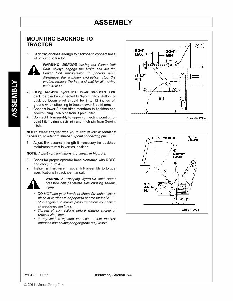
MOUNTING BACKHOE TO TRACTOR
1. Back tractor close enough to backhoe to connect hosekit or pump to tractor.
WARNING: BEFORE leaving the Power UnitSeat, always engage the brake and set thePower Unit transmission in parking gear,disengage the auxiliary hydraulics, stop theengine, remove the key, and wait for all movingparts to stop.
2. Using backhoe hydraulics, lower stabilizers untilbackhoe can be connected to 3-point hitch. Bottom ofbackhoe boom pivot should be 8 to 12 inches offground when attaching to tractor lower 3-point arms.
3. Connect lower 3-point hitch members to backhoe andsecure using linch pins from 3-point hitch.
4. Connect link assembly to upper connecting point on 3-point hitch using clevis pin and linch pin from 3-pointhitch.
NOTE: Insert adapter tube (5) in end of link assembly ifnecessary to adapt to smaller 3-point connecting pin.
5. Adjust link assembly length if necessary for backhoemainframe to rest in vertical position.
NOTE: Adjustment limitations are shown in Figure 3.
6. Check for proper operator head clearance with ROPSand cab (Figure 4).
7. Tighten all hardware in upper link assembly to torquespecifications in backhoe manual.
WARNING: Escaping hydraulic fluid underpressure can penetrate skin causing seriousinjury.
• DO NOT use your hands to check for leaks. Use apiece of cardboard or paper to search for leaks.
• Stop engine and relieve pressure before connectingor disconnecting lines.
• Tighten all connections before starting engine orpressurizing lines.
• If any fluid is injected into skin, obtain medicalattention immediately or gangrene may result.
75CBH 11/11 Assembly Section 3-4
© 2011 Alamo Group Inc.

Operation Section 4-1
OPERATION SECTION
OPERATIONO
PE
RA
TIO
N
CAUTION: To avoid possible injury, observethe following safety rules BEFOREOPERATING backhoe.
• Be sure area is clear of underground utilities or other hazards.
• Position a barricade around work area.
• Keep bystanders a safe distance away.
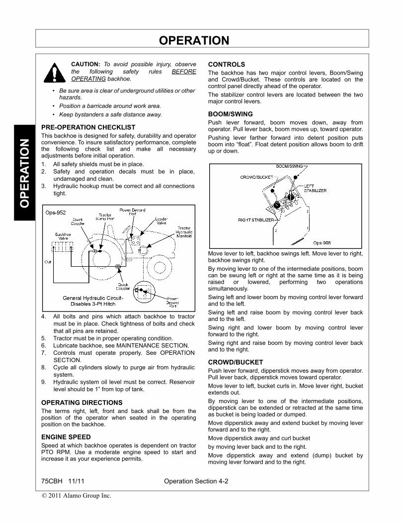
PRE-OPERATION CHECKLISTThis backhoe is designed for safety, durability and operatorconvenience. To insure satisfactory performance, completethe following check list and make all necessaryadjustments before initial operation.
1. All safety shields must be in place.2. Safety and operation decals must be in place,
undamaged and clean.3. Hydraulic hookup must be correct and all connections
tight.
4. All bolts and pins which attach backhoe to tractormust be in place. Check tightness of bolts and checkthat all pins are retained.
5. Tractor must be in proper operating condition.6. Lubricate backhoe, see MAINTENANCE SECTION.7. Controls must operate properly. See OPERATION
SECTION.8. Cycle all cylinders slowly to purge air from hydraulic
system.9. Hydraulic system oil level must be correct. Reservoir
level should be 1” from top of tank.
OPERATING DIRECTIONSThe terms right, left, front and back shall be from theposition of the operator when seated in the operatingposition on the backhoe.
ENGINE SPEEDSpeed at which backhoe operates is dependent on tractorPTO RPM. Use a moderate engine speed to start andincrease it as your experience permits.
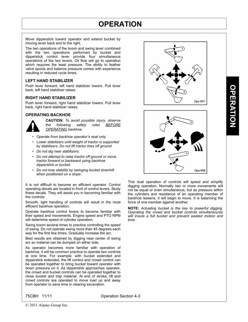
CONTROLSThe backhoe has two major control levers, Boom/Swingand Crowd/Bucket. These controls are located on thecontrol panel directly ahead of the operator.
The stabilizer control levers are located between the twomajor control levers.
BOOM/SWINGPush lever forward, boom moves down, away fromoperator. Pull lever back, boom moves up, toward operator.
Pushing lever farther forward into detent position putsboom into “float”. Float detent position allows boom to driftup or down.
Move lever to left, backhoe swings left. Move lever to right,backhoe swings right.
By moving lever to one of the intermediate positions, boomcan be swung left or right at the same time as it is beingraised or lowered, performing two operationssimultaneously.
Swing left and lower boom by moving control lever forwardand to the left.
Swing left and raise boom by moving control lever backand to the left.
Swing right and lower boom by moving control leverforward to the right.
Swing right and raise boom by moving control lever backand to the right.
CROWD/BUCKETPush lever forward, dipperstick moves away from operator.Pull lever back, dipperstick moves toward operator.
Move lever to left, bucket curls in. Move lever right, bucketextends out.
By moving lever to one of the intermediate positions,dipperstick can be extended or retracted at the same timeas bucket is being loaded or dumped.
Move dipperstick away and extend bucket by moving leverforward and to the right.
Move dipperstick away and curl bucket
by moving lever back and to the right.
Move dipperstick away and extend (dump) bucket bymoving lever forward and to the right.
75CBH 11/11 Operation Section 4-2
© 2011 Alamo Group Inc.
OPERATIONO
PE
RA
TIO
N
Move dipperstick toward operator and extend bucket bymoving lever back and to the right.
The two operations of the boom and swing lever combinedwith the two operations performed by bucket anddipperstick control lever provide four simultaneousoperations of the two levers. Oil flow will go to operationwhich requires the least pressure. The ability to feathervalve spools and balance pressure comes with experienceresulting in reduced cycle times.
LEFT HAND STABILIZERPush lever forward, left hand stabilizer lowers. Pull leverback, left hand stabilizer raises.
RIGHT HAND STABILIZERPush lever forward, right hand stabilizer lowers. Pull leverback, right hand stabilizer raises.
OPERATING BACKHOECAUTION: To avoid possible injury, observethe following safety rules BEFOREOPERATING backhoe.
• Operate from backhoe operator’s seat only.
• Lower stabilizers until weight of tractor is supported by stabilizers. Do not lift tractor tires off ground.
• Do not dig near stabilizers.
• Do not attempt to raise tractor off ground or move tractor forward or backward using backhoe dipperstick or bucket.
• Do not lose stability by swinging bucket downhill when positioned on a slope.
It is not difficult to become an efficient operator. Controloperating decals are located in front of control levers. Studythese decals. They will assist you in becoming familiar withthe controls.
Smooth, light handling of controls will result in the mostefficient backhoe operation.
Operate backhoe control levers to become familiar withtheir speed and movements. Engine speed and PTO RPMwill determine speed of cylinder operation.
Swing boom several times to practice controlling the speedof swing. Do not operate swing more than 45 degrees eachway for the first few times. Gradually increase the arc.
Best results are obtained by digging near center of swingarc so material can be dumped on either side.
As operator becomes more familiar with operation ofbackhoe, it will be common practice to operate two controlsat one time. For example, with bucket extended anddipperstick extended, the lift control and crowd control canbe operated together to bring bucket toward operator withdown pressure on it. As dipperstick approaches operator,the crowd and bucket controls can be operated together toclose bucket and trap material. At end of stroke, lift andcrowd controls are operated to move load up and awayfrom operator to save time in clearing excavation.
This dual operation of controls will speed and simplifydigging operation. Normally two or more movements willnot be equal or even simultaneous, but as pressure withinthe cylinders and resistance of an operating member ofbackhoe lessens, it will begin to move. It is balancing theforce of one member against another.
NOTE: Actuating bucket is the key to powerful digging.Operating the crowd and bucket controls simultaneouslywill insure a full bucket and prevent wasted motion andtime.
75CBH 11/11 Operation Section 4-3
© 2011 Alamo Group Inc.
OPERATIONO
PE
RA
TIO
N
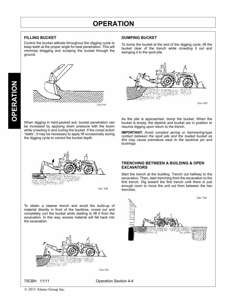
FILLING BUCKETControl the bucket attitude throughout the digging cycle tokeep teeth at the proper angle for best penetration. This willminimize dragging and scraping the bucket through theground.
When digging in hard-packed soil, bucket penetration canbe increased by applying down pressure with the boomwhile crowding in and curling the bucket. If the crowd action“stalls”, it may be necessary to apply lift occasionally duringthe digging cycle to correct the bucket depth.
To obtain a cleaner trench and avoid the build-up ofmaterial directly in front of the backhoe, crowd out andcompletely curl the bucket while starting to lift it from theexcavation. In this way, excess material will fall back intothe excavation.
DUMPING BUCKET
To dump the bucket at the end of the digging cycle, lift thebucket clear of the trench while crowding it out andswinging it to the spoil pile.
As the pile is approached, dump the bucket. When thebucket is empty, the dipstick and bucket are in position toresume digging upon return to the trench.
IMPORTANT: Avoid constant jarring or hammering-typecontact between the spoil pile and the loaded bucket asthis may cause premature wear to the backhoe pin andbushings.
TRENCHING BETWEEN A BUILDING & OPEN EXCAVATORS
Start the trench at the building. Trench out halfway to theexcavation. Then, start trenching from the excavation to thefirst trench. Dig toward the first trench until there is justenough room to move the unit out from between the twotrenches.
75CBH 11/11 Operation Section 4-4
© 2011 Alamo Group Inc.
OPERATIONO
PE
RA
TIO
N
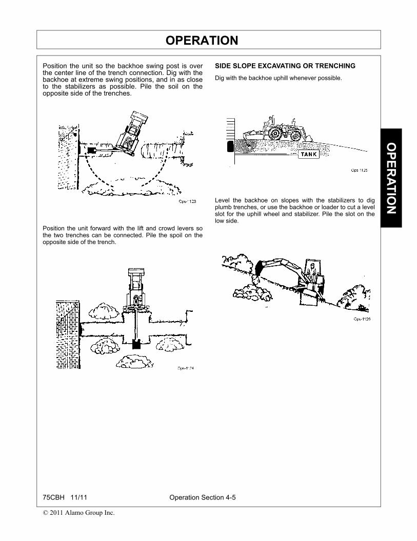
Position the unit so the backhoe swing post is overthe center line of the trench connection. Dig with thebackhoe at extreme swing positions, and in as closeto the stabilizers as possible. Pile the soil on theopposite side of the trenches.
Position the unit forward with the lift and crowd levers sothe two trenches can be connected. Pile the spoil on theopposite side of the trench.
SIDE SLOPE EXCAVATING OR TRENCHING
Dig with the backhoe uphill whenever possible.
Level the backhoe on slopes with the stabilizers to digplumb trenches, or use the backhoe or loader to cut a levelslot for the uphill wheel and stabilizer. Pile the slot on thelow side.
75CBH 11/11 Operation Section 4-5
© 2011 Alamo Group Inc.
OPERATIONO
PE
RA
TIO
N
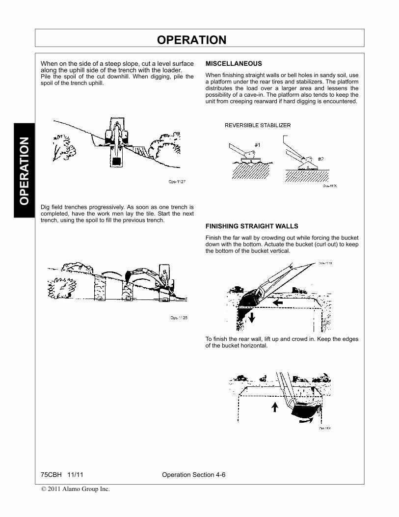
When on the side of a steep slope, cut a level surfacealong the uphill side of the trench with the loader.Pile the spoil of the cut downhill. When digging, pile thespoil of the trench uphill.
Dig field trenches progressively. As soon as one trench iscompleted, have the work men lay the tile. Start the nexttrench, using the spoil to fill the previous trench.
MISCELLANEOUS
When finishing straight walls or bell holes in sandy soil, usea platform under the rear tires and stabilizers. The platformdistributes the load over a larger area and lessens thepossibility of a cave-in. The platform also tends to keep theunit from creeping rearward if hard digging is encountered.
FINISHING STRAIGHT WALLS
Finish the far wall by crowding out while forcing the bucketdown with the bottom. Actuate the bucket (curl out) to keepthe bottom of the bucket vertical.
To finish the rear wall, lift up and crowd in. Keep the edgesof the bucket horizontal.
75CBH 11/11 Operation Section 4-6
© 2011 Alamo Group Inc.
OPERATIONO
PE
RA
TIO
N
BACKFILLINGBackfill by lifting the bucket over the spoil pile and thencrowding in. Pull both the crowd and lift levers for smooth,even backfilling.
IMPORTANT: Do not backfill by using the swing circuit anddragging the bucket sideways. Doing so can causedamage to the dipstick, boom, swing cylinders, ormainframe.
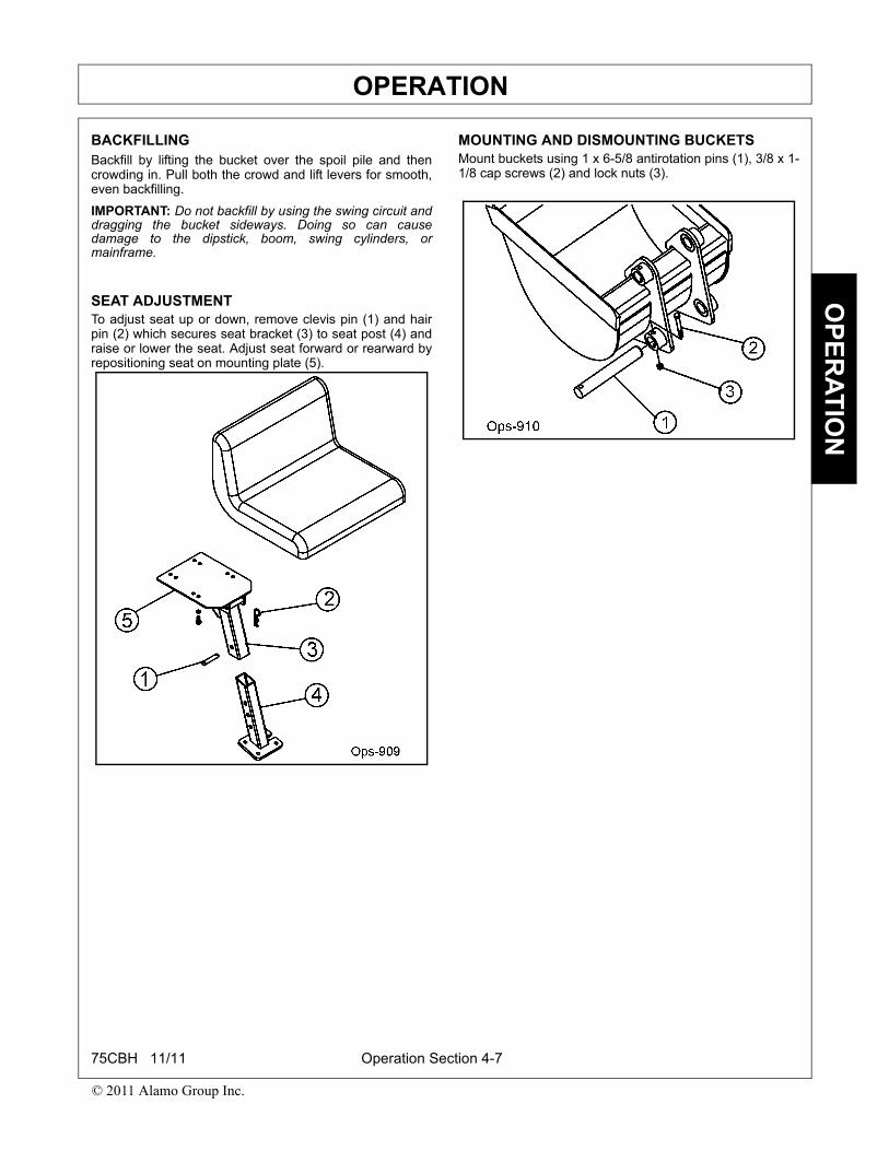
SEAT ADJUSTMENTTo adjust seat up or down, remove clevis pin (1) and hairpin (2) which secures seat bracket (3) to seat post (4) andraise or lower the seat. Adjust seat forward or rearward byrepositioning seat on mounting plate (5).
MOUNTING AND DISMOUNTING BUCKETSMount buckets using 1 x 6-5/8 antirotation pins (1), 3/8 x 1-1/8 cap screws (2) and lock nuts (3).
75CBH 11/11 Operation Section 4-7
© 2011 Alamo Group Inc.
OPERATIONO
PE
RA
TIO
N
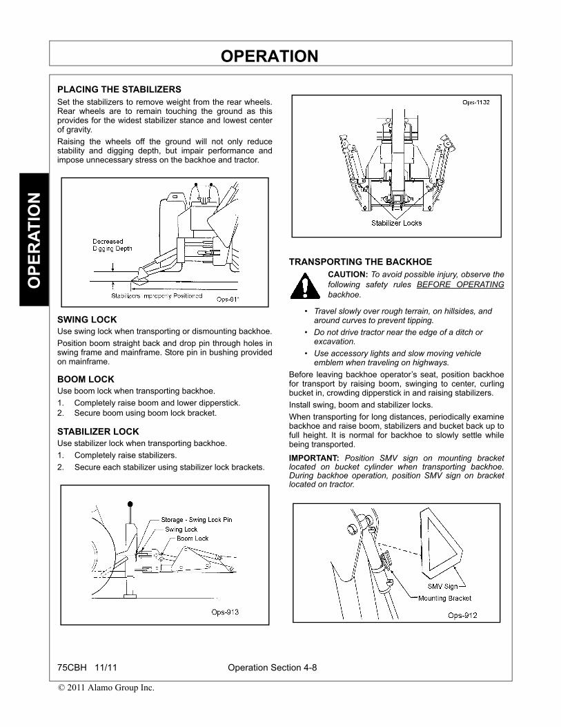
PLACING THE STABILIZERSSet the stabilizers to remove weight from the rear wheels.Rear wheels are to remain touching the ground as thisprovides for the widest stabilizer stance and lowest centerof gravity.
Raising the wheels off the ground will not only reducestability and digging depth, but impair performance andimpose unnecessary stress on the backhoe and tractor.
SWING LOCKUse swing lock when transporting or dismounting backhoe.
Position boom straight back and drop pin through holes inswing frame and mainframe. Store pin in bushing providedon mainframe.
BOOM LOCKUse boom lock when transporting backhoe.
1. Completely raise boom and lower dipperstick.2. Secure boom using boom lock bracket.
STABILIZER LOCKUse stabilizer lock when transporting backhoe.
1. Completely raise stabilizers.
2. Secure each stabilizer using stabilizer lock brackets.
TRANSPORTING THE BACKHOECAUTION: To avoid possible injury, observe thefollowing safety rules BEFORE OPERATINGbackhoe.
• Travel slowly over rough terrain, on hillsides, and around curves to prevent tipping.
• Do not drive tractor near the edge of a ditch or excavation.
• Use accessory lights and slow moving vehicle emblem when traveling on highways.
Before leaving backhoe operator’s seat, position backhoefor transport by raising boom, swinging to center, curlingbucket in, crowding dipperstick in and raising stabilizers.
Install swing, boom and stabilizer locks.
When transporting for long distances, periodically examinebackhoe and raise boom, stabilizers and bucket back up tofull height. It is normal for backhoe to slowly settle whilebeing transported.
IMPORTANT: Position SMV sign on mounting bracketlocated on bucket cylinder when transporting backhoe.During backhoe operation, position SMV sign on bracketlocated on tractor.
75CBH 11/11 Operation Section 4-8
© 2011 Alamo Group Inc.
OPERATIONO
PE
RA
TIO
N
REMOVAL FROM TRACTOR - STORAGEBackhoe is self-assisting during installation and removalprocedures.
1. Put stabilizers down and lift backhoe slightly. Rotateboom straight back.
2. Install swing lock pin.3. Complete raise boom and lower dipperstick. Curl
bucket until bottom of bucket is level with ground.Lower boom until bucket rests firmly on ground.
4. Remove pins which secure backhoe to tractor.5. Slowly drive forward until tractor clears backhoe.
Engage tractor brakes.6. Lower backhoe by raising stabilizers and boom until
backhoe or subframe rests on suitable blocking. Leavestabilizers touching ground.
NOTE: For added stability, rest backhoe or subframe onwood blocks or plywood.
7. Shut off tractor. Work handles back and forth to relievehydraulic pressure. Disconnect hydraulic lines or pumpfrom backhoe.
8. For long term storage, coat all exposed cylinder rodswith grease.
9. Lubricate all grease fittings, stabilizer pivot pins andcomplete handle linkage.
WARNING: To avoid injury during removal ofbackhoe:
• Do not permit bystanders within 15 feet.
• Dismount backhoe on firm level ground.
• Always shut off tractor engine, disengage PTO and relieve pressure before disconnecting oil lines.
75CBH 11/11 Operation Section 4-9
© 2011 Alamo Group Inc.


Maintenance Section 5-1
MAINTENANCE SECTION
MAINTENANCEM
AIN
TE
NA
NC
E
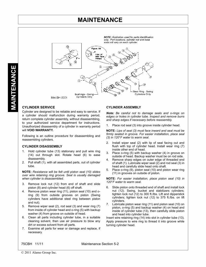
CYLINDER SERVICECylinder are designed to be reliable and easy to service. Ifa cylinder should malfunction during warranty period,return complete cylinder assembly, without disassembling,to your authorized service department for instructions.Unauthorized disassembly of a cylinder in warranty periodwill VOID WARRANTY.
Following is an outline procedure for disassembling andreassembling cylinders.
CYLINDER DISASSEMBLY
1. Hold cylinder tube (13) stationary and pull wire ring(14) out through slot. Rotate head (6) to easedisassembly.
2. Pull shaft (1), with all assembled parts, out of cylindertube.
NOTE: Resistance will be felt until piston seal (10) slidesover wire retaining ring groove. Seal is usually damagedwhen cylinder is disassembled.
3. Remove lock nut (12) from end of shaft and slidepiston (8) and cylinder head (6) off shaft.
4. Remove piston wear ring (11), piston seal (10) and o-ring (9) from outside grooves on piston (Swingcylinders have additional steel ring between pistonand nut).
5. Remove wiper seal (2), rod seal (3) and wear ring (7)from inside of cylinder head and o-ring (5) with backupwasher (4) from groove on outside of head.
6. Clean all parts including cylinder tube, in a suitablecleaning solvent, then use air pressure to blow anydirt or excess solvent from all parts.
7. Examine all parts for wear or damage and replace, ifnecessary.
CYLINDER ASSEMBLY
Note: Be careful not to damage seals and o-rings onedges or holes in cylinder tube. Inspect and remove burrsand sharp edges if necessary before reassembly.
1. Place rod seal (3) into groove inside cylinder head.
NOTE: Lips of seal (3) must face inward and seal must befirmly seated in groove. For easier installation, place seal(3) in 120°F water to warm seal.
2. Install wiper seal (2) with lip of seal facing out andflush with top of cylinder head. Install wear ring (7)inside other end of head.
3. Place o-ring (5) with backup washer (4) in groove onoutside of head. Backup washer must be on rod side.
4. Remove sharp edges on outer edge of threaded endof shaft (1). Lubricate wiper seal (2) and rod seal (3) inhead and carefully slide head onto shaft.
5. Place o-ring (9), piston seal (10) and piston wear ring(11) in grooves on outside of piston.
NOTE: For easier installation, place piston seal (10) in120°F water to warm seal.
6. Slide piston onto threaded end of shaft and install locknut (12). Swing, bucket and stabilizers cylinders;tighten lock nut (12) to 300 ft./lbs. Lift and dipperstickcylinders; tighten lock nut (12) to 375 ft./lbs. on liftcylinders.
7. Lubricate piston wear ring (11) and piston seal (10) onpiston, o-ring (5) and backup washer (4) on head andinside of cylinder tube (13), then carefully slide pistonand head into cylinder tube.
Insert wire retaining ring (14) into slot in cylinder tube (13).Apply pressure to wire ring to thread it into groove whileturning cylinder head.
75CBH 11/11 Maintenance Section 5-2
© 2011 Alamo Group Inc.
MAINTENANCEM
AIN
TE
NA
NC
E
CAUTION: To avoid possible injury, observethe following safety rules when servicingbackhoe.
• Do not oil, grease or adjust backhoe while it is in motion.
• Do not change any backhoe relief valve settings. Relief valve settings are factory set for best backhoe performance and safety.
• Escaping fluid under pressure can have sufficient force to penetrate the skin and cause serious injury. Be sure to relieve all presure before disconnecting lines. Be sure all connections are tight and that lines, pipes and hoses are not damaged before applying pressure to the system.
• Fluid escaping from a very small hole can be almost invisible. Use a piece of cardboard or wood - not your hands - to search for suspected leaks.
• See a doctor at once if injured by escaping fluid. Serious infection or reaction can develop if proper medical treatment is not administered immediately.
• Protect your eyes - wear safety glasses. Guard against injury when driving connecting pins or performing any repair in which particles can chip from work piece or striking tool.
BEGINNING OF SEASONRemove all protective covering. Remove excessive greasefrom cylinder rods if unit has been in long term storage.
Check hydraulic hoses for deterioration and replace ifnecessary. Caution, hydraulic hoses may be underpressure. Make sure pressure has been relieved beforeremoving hoses.
Lubricate all grease fittings and oil handle linkage.
Clean and inspect all safety and operation decals. Replacemissing or damaged decals.
Replace oil filter.
Fill hydraulic fluid to proper level.
Tighten all loose bolts, nuts and set screws (See Torquechart).
Sharpen or replace worn bucket teeth.
Operate backhoe slowly for a short time before placing unitunder full load.
Fully cycle backhoe through all movements several timesto purge air from system.
HYDRAULIC HOSES
WARNING: Escaping hydraulic fluid underpressure can penetrate skin causing seriousinjury.
• DO NOT use your hand to check for leaks. Use a piece of cardboard or paper to search for leaks.
• Stop engine and relieve pressure before connecting or disconnecting lines.
• Tighten all connections before starting engine or pressurizing lines.
• Oil leaks on the suction side will draw air into the system, causing oil in reservoir to appear foamy.
• When tightening connections, always use two wrenches.
IMPORTANT: Do not overtighten fittings. Make them justtight enough to eliminate leaks.
NOTE: Apply sealant only to all tapered threads unlesscoupled with swivel adapters. When using teflon tape, wraptape clockwise (as viewed from end) and wrap tape onlytwice. Keep sealant away front first two threads of taperedend to prevent contamination of hydraulic fluid. Do not usesealant on o-ring or flare adapter threads.
Hoses on backhoe are very severely worked and will fail intime. Examine them regularly and replace any that showsigns of failure. Pay careful attention to routing of hoses sothey can move freely, without kinking and cannot bepinched or cut by any part of backhoe.
HYDRAULIC SYSTEM RESERVOIRMaintain reservoir fluid level at 1 inch below tank top whenbucket is extended to full reach, bucket rolled back forloading and resting on the ground, and stabilizers fullyraised. If reservoir is overfilled, fluid may be forced out ofbreather cap.
Fill with SAE 10W engine oil with API”SD” classification innorthern climates and SAE 40W engine oil with API”SD”classification in southern climates.
Change oil and filter every 200 hours or more often ifnecessary.
75CBH 11/11 Maintenance Section 5-3
© 2011 Alamo Group Inc.
MAINTENANCEM
AIN
TE
NA
NC
E
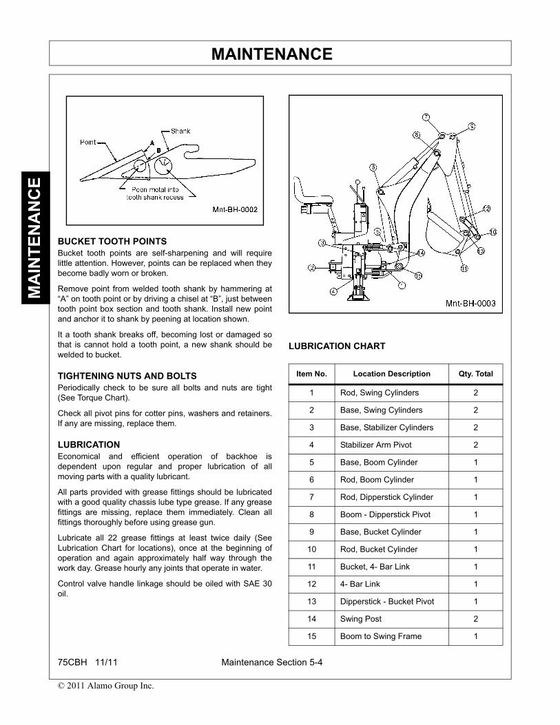
BUCKET TOOTH POINTSBucket tooth points are self-sharpening and will requirelittle attention. However, points can be replaced when theybecome badly worn or broken.
Remove point from welded tooth shank by hammering at“A” on tooth point or by driving a chisel at “B”, just betweentooth point box section and tooth shank. Install new pointand anchor it to shank by peening at location shown.
It a tooth shank breaks off, becoming lost or damaged sothat is cannot hold a tooth point, a new shank should bewelded to bucket.
TIGHTENING NUTS AND BOLTSPeriodically check to be sure all bolts and nuts are tight(See Torque Chart).
Check all pivot pins for cotter pins, washers and retainers.If any are missing, replace them.
LUBRICATIONEconomical and efficient operation of backhoe isdependent upon regular and proper lubrication of allmoving parts with a quality lubricant.
All parts provided with grease fittings should be lubricatedwith a good quality chassis lube type grease. If any greasefittings are missing, replace them immediately. Clean allfittings thoroughly before using grease gun.
Lubricate all 22 grease fittings at least twice daily (SeeLubrication Chart for locations), once at the beginning ofoperation and again approximately half way through thework day. Grease hourly any joints that operate in water.
Control valve handle linkage should be oiled with SAE 30oil.
LUBRICATION CHART
Item No. Location Description Qty. Total
1 Rod, Swing Cylinders 2
2 Base, Swing Cylinders 2
3 Base, Stabilizer Cylinders 2
4 Stabilizer Arm Pivot 2
5 Base, Boom Cylinder 1
6 Rod, Boom Cylinder 1
7 Rod, Dipperstick Cylinder 1
8 Boom - Dipperstick Pivot 1
9 Base, Bucket Cylinder 1
10 Rod, Bucket Cylinder 1
11 Bucket, 4- Bar Link 1
12 4- Bar Link 1
13 Dipperstick - Bucket Pivot 1
14 Swing Post 2
15 Boom to Swing Frame 1
75CBH 11/11 Maintenance Section 5-4
© 2011 Alamo Group Inc.

MAINTENANCEM
AIN
TE
NA
NC
E
HYDRAULIC TROUBLESHOOTING
Hydraulic troubleshooting material presented in this sectionis offered as a guide to diagnosing probable causes andremedies for general operational problems.
Match your problem wiht the typical problem examplesgiven in the possible cause column. These numberscorrespond with the possible cause and correctionparagraphs that follow.
NOTE: If, when using the following chart, it is decided thatoverhaul of components or pressure adjustment isnecessary, it is recommended that your dealer make theserepairs. He is equipped to do this work.
PROBLEM POSSIBLE CAUSE
Machine fails to operate when initially started.
1, 2, 5, 7, 15, 23
Machine looses power after initially operating satisfactorily.
1, 8, 10, 15, 23
Loss of power in lift or crowd cylinder, but other cylinders function properly
22, 24, 28
Loss of power in any one cylinder including lift and crowd
8, 9, 10, 11, 12, 13, 22, 23, 25
Loss of power or loss of cushioning action in swing cylinders, but other cylinders function properly.
8, 9, 10, 11, 12, 13, 22, 23, 25
Maximum swing action cannot be obtained.
12, 14
Slow operation of machine (lack of power) all cylinders.
1, 4, 6, 15, 23
Spongy or jerky action of cylinders and/ or noisy operation.
1, 3, 4, 5
Lift crowd or bucket cylinders drop under load when lever spools are shifted from neutral.
26, 28
Load drops or settles. 8, 10, 13, 25, 26
Leaky cylinders. 10, 11, 12, 13
Leaky valve. 8, 15, 16, 27
Sticky valve spool. 16, 19, 20, 21
Unable to push valve spool in.
16, 17, 20, 21
Spring centered spools do not return to neutral.
16, 17, 18, 19, 20, 21
POSSIBLE CAUSE CORRECTIVE ACTION
1 Low oil level in reservoir.
Fill reservoir to proper level.
2 No oil supply to machine.
Engage tractor PTO.
3 Air in system. Purge all circuits of air by operating all cylinders through full movements several times. Check oil in reservoir for foaming. Check all suction lines for leaks. Fill reservoir to correct level.
4 Oil viscosity too heavy or oil is not at operating temperature.
Use recommended hydraulic fluid. Run machine until it reaches operating temperature.
5 Pump not running. Check PTO to be sure it is engaged. Pump connected to PTO.
6 Insufficient pumping. Advance engine throttle.
7 Improper hose connection.
IMPORTANT: Be sure inlet and return hoses are hooked up correctly. Improper hookup will result in damage to backhoe valve.
8 Loose hydraulic connections, leaks in fittings or hoses.
Tighten all hose connections and replace all damaged o-rings at leaking o-ring fittings. Check and replace any damaged hoses.
9 Restriction in fittings or hoses.
Check and replace any damaged hoses and fittings. Check for pinched hoses.
10 Oil is bypassing cylinder piston.
Replace or rebuild cylinder. Replace damaged parts.
11 Scored piston rods or worn rod guides in cylinder.
Replace or rebuild cylinder. Replace damaged parts.
12 Bent piston rod in cylinder
Replace or rebuild cylinder. Replace damaged parts
PROBLEM POSSIBLE CAUSE
75CBH 11/11 Maintenance Section 5-5
© 2011 Alamo Group Inc.

MAINTENANCEM
AIN
TE
NA
NC
E
30.This valve is a precision device and is not intended forextensive field adjustment or repair. Field replacementparts are limited to seal kits, cartridges and tie rodends. Beyond replacement of these parts, opening ofcheck cavities and certain relief valve cavities toexamine for trapped dirt, or resetting main relief valvewith the use of a good pressure gauge, valve should bereturned for service.
Dirt and shreds of packing material are the usual causes ofvalve malfunction. Be sure that oil supply is kept clean. Useonly factory supplied packings in cylinder repair. Fittingsand hoses must be clean before being removed.
NOTE: Pay close attention to all caution warning notes sovalve will not have to be returned to manufacturer forreconditioning.
Troubleshooting guide is designed to help qualifiedindividuals, with valve service training, correct minorproblems which may develop. If valve is under warranty donot attempt disassembly for repairs. Contact yourauthorized dealer. Any attempt to disassemble valve duringwarranty period will VOID warranty.
13 Worn or damaged rod seals on cylinder. External leaks.
Re-pack cylinder. Rebuild cylinder replacing damaged parts as necessary.
14 Swing linkage jammed.
Remove interference.
15 Excessive back pressure.
Restriction between “in” and “out” port and reservoir.
16 Paint on valve spool. Sticking valve spool, or scored valve.
Clean valve spool. Binding may be caused by over tightened plug, mounting bolt, fitting or tie rod bolt. See Item 30.
17 Oil leakage past spool seal into spool cap.
If spool cap contains oil, replace spool seal o-ring. If o-ring retainer is “bellied”, check for restriction from “out” port reservoir. See Item 30.
18 Broken return springs.
Replace broken return springs.
19 Bent spool. Return for factory repair or replace with new spool section. See Item 30.
20 Foreign particles. Clean system and valve.
21 Misalignment of control handle linkage.
Check linkage for binding condition.
22 Spool not moved to full stroke.
Spool travel should be 5/16” either way or 5/8” total.
23 Relief valve setting in control valve too low or defective.
Clean or overhaul relief valve or replace cartridge. Refer to VALVE SERVICE section for proper PSI settings.
24 Overload relief valve in control valve stuck open or malfunctioning.
Clean relief. Do not disturb pressure setting or replace cartridge.
25 Worn control valve. Replace control valve.
26 Check poppet in control valve not holding.
Clean check poppet(s) carefully. Ensure free movement and proper seating or replace check poppet. See Item 30.
27 Damaged or worn spool seals.
Replace spool end seals.
POSSIBLE CAUSE CORRECTIVE ACTION
28 Check ball in anti-cavitation is stuck or not seated properly.
Clean anti-cavitation valve carefully. Assure that checks move freely and seat properly or replace cartridge. See Item 30.
29 Valve cap and center return mechanism binding.
Loosen screws holding cap on valve (ref. Valve Service image). Operate valve spool and retighten screws.
POSSIBLE CAUSE CORRECTIVE ACTION
75CBH 11/11 Maintenance Section 5-6
© 2011 Alamo Group Inc.
MAINTENANCEM
AIN
TE
NA
NC
E
VALVE SERVICE
Top of valve is defined as side where joysticks areinstalled.
Before servicing valve, make sure backhoe has boomlocked, stabilizers locked, and dipper in down position.Shut off tractor and relieve pressure by activating valvehandles. Use a drip pan below backhoe to catch anyescaping oil during removal of valve.
WARNING: Failure to lock booms andstabilizer and relieve pressure in valve cancause serious injury from equipment fallingwhen hydraulic pressure is released by theremoval of valve.
MAIN RELIEF REPLACEMENT
1. Use a socket to remove main relief from valvehousing.
2. Inspect new relief to ensure seal is properly installed,and apply grease around the relief.
3. Ensure that pressure setting stamped on new reliefmatches the setting of old relief.
4. Install o-rings on relief.5. Insert relief and torque to 60 ft./lbs.
SPOOL SEAL INSTALLATION
1. Remove the mechanical joystick kit from the top of thevalve and the return kit from the bottom.
2. Remove the old o-rings and leave spool in housing,making sure spool is in center position.
3. Lightly oil one seal and insert it in top of valve. Slidethe seal into position in the groove in the valve body,making sure that it does not fall into the spool groove.
4. Lightly oil a second o-ring and insert in bottom ofvalve. Slide the seal into position in the groove in thevalve body making sure it does not fall into the spoolgroove. Do not push on the spool as it may cause thefirst seal to come out of the groove.
WARNING: If either of the seals falls in thespool groove, it may be cut when the spoolmoves. If this happens, make sure to gentlyremove the seal from the groove, andreposition seal after inspecting for cuts in thehousing groove once the spool is back incenter position.
5. Reinstall the mechanical joystick kit on the top of thevalve and return kit on the bottom.
TORQUE SETTINGS
1. Main Relief Body: 60 ft./lbs.
2. Load Check Valve: 15 ft./lbs.
3. Screws: 4 ft./lbs.
75CBH 11/11 Maintenance Section 5-7
© 2011 Alamo Group Inc.

MAINTENANCEM
AIN
TE
NA
NC
E
75CBH 11/11 Maintenance Section 5-8
© 2011 Alamo Group Inc.

MAINTENANCEM
AIN
TE
NA
NC
E
PARTS LIST
ITEM DESCRIPTION QTY.NO.1 O-RING 12 O-RING 13 VALVE BODY/RELIEF 14 PISTON 15 SPRING 16 O-RING 17 REGISTER 18 NUT, M16-1.5 19 DEFLECTOR 110 O-RING 511 CENTERING RING 512 SPRING 513 SPACER 1014 SCREW 515 CAP 2016 SCREW 2017 SCREW 418 CIRCLIP 119 WASHER 120 BUSHING 121 SPRING 122 BALL HOLDER 123 STEEL BALL D.5 324 STEEL BALL D.7 125 CAP 126 WASHER 127 SPACER 128 SPRING 129 SPACER 130 CENTERING RING 131 O-RING 15.10 X 2.70 X 1.5 132 PLUG 433 COPPER GASKET 14 X 20 X 15 434 REGISTER 435 SPRING 436 PISTON 437 VALVE BODY/RELIEF 438 O-RING 17.17 X 1.78 439 O-RING 440 PLUG 141 O-RING 17.17 X 1.78 142 O-RING 143 PLUG 644 SPRING 645 O-RING 11.11 X 1.78 646 BODY 647 PLUG 148 LEVER 249 RUBBER BELLOWS 250 HOUSING/LEVER 2
ITEM DESCRIPTION QTY.NO.51 O-RING 15.10 X 2.70 252 CENTERING RING 253 LEVER PIN 254 SCREW 855 O-RING 15.10 X 2.70 456 NUT 357 PLATE/JOYSTICK 158 SCREW 859 ASSEMBLY 260 ASSEMBLY 261 PIN 262 FLANGE 163 SCREW 664 NUT, M7 465 O-RING GASKET 266 RUBBER BELLOWS 267 SCREW 468 ARICULATION 269 NUT, M6 270 FLANGE 171 CENTERING RING 172 O-RING 15.60 X 1.78 173 PLATE/JOYSTICK 174 VALVE BLOCK 175 PLUG 1
*This parts list is provided to aid in maintenance andservicing only. Service parts are sold in kits only.
75CBH 11/11 Maintenance Section 5-9
© 2011 Alamo Group Inc.

MAINTENANCEM
AIN
TE
NA
NC
E
PROPER TORQUE FOR FASTENERS
75CBH 11/11 Maintenance Section 5-10
© 2011 Alamo Group Inc.


LIMITED WARRANTY
Bush Hog warrants to the original purchaser of any new Bush Hog equipment, purchased from an authorized BushHog dealer, that the equipment be free from defects in material and workmanship for a period of one (1) year fornon-commercial, state and municipalities’ use and ninety (90) days for commercial use from date of retail sale. Theobligation of Bush Hog to the purchaser under this warranty is limited to the repair or replacement of defectiveparts.
Replacement or repair parts installed in the equipment covered by this limited warranty are warranted for ninety(90) days from the date of purchase of such part or to the expiration of the applicable new equipment warrantyperiod, whichever occurs later. Warranted parts shall be provided at no cost to the user at an authorized Bush Hogdealer during regular working hours. Bush Hog reserves the right to inspect any equipment or parts which areclaimed to have been defective in material or workmanship.
DISCLAIMER OF IMPLIED WARRANTIES & CONSEQUENTIAL DAMAGESBush Hog’s obligation under this limited warranty, to the extent allowed by law, is in lieu of all warranties, implied orexpressed, INCLUDING IMPLIED WARRANTIES OF MERCHANTABILITY AND FITNESS FOR A PARTICULARPURPOSE and any liability for incidental and consequential damages with respect to the sale or use of the itemswarranted. Such incidental and consequential damages shall include but not be limited to: transportation chargesother than normal freight charges; cost of installation other than cost approved by Bush Hog; duty; taxes; chargesfor normal service or adjustment; loss of crops or any other loss of income; rental of substitute equipment,expenses due to loss, damage, detention or delay in the delivery of equipment or parts resulting from acts beyondthe control of Bush Hog.
THIS LIMITED WARRANTY SHALL NOT APPLY:1. To vendor items which carry their own warranties, such as engines, tires, and tubes.2. If the unit has been subjected to misapplication, abuse, misuse, negligence, fire or other accident.3. If parts not made or supplied by Bush Hog have been used in connection with the unit, if, in the sole judgement
of Bush Hog such use affects its performance, stability or reliability.4. If the unit has been altered or repaired outside of an authorized Bush Hog dealership in a manner which, in the
sole judgement of Bush Hog, affects its performance, stability or reliability.5. To normal maintenance service and normal replacement items such as gearbox lubricant, hydraulic fluid, worn
blades, or to normal deterioration of such things as belts and exterior finish due to use or exposure.6. To expendable or wear items such as teeth, chains, sprockets, belts, springs and any other items that in the
company’s sole judgement is a wear item.
NO EMPLOYEE OR REPRESENTATIVE OF BUSH HOG IS AUTHORIZED TO CHANGE THIS LIMITEDWARRANTY IN ANY WAY OR GRANT ANY OTHER WARRANTY UNLESS SUCH CHANGE IS MADE INWRITING AND SIGNED BY BUSH HOG’S SERVICE MANAGER, 2501 GRIFFIN AVE., SELMA, ALABAMA36703.
Record the model number, serial number and date
purchased. This information will be helpful to your
dealer if parts or service are required.
MAKE CERTAIN THE WARRANTY
HAS BEEN FILED WITH BUSH HOG
SELMA, ALABAMA
MODEL NUMBER ___________________________
SERIAL NUMBER ___________________________
DATE OF RETAIL SALE ______________________

TO THE OWNER/OPERATOR/DEALER
To keep your implement running efficiently and safely, read your manual thoroughly and follow these directionsand the Safety Messages in this Manual. The Table of Contents clearly identifies each section where you caneasily find the information you need.The OCCUPATIONAL SAFETY AND HEALTH ACT (1928.51 Subpart C) makes these minimum safetyrequirements of tractor operators:
REQUIRED OF THE OWNER:1. Provide a Roll-Over-Protective Structure that meets the requirements of this Standard; and2. Provide Seat belts that meet the requirements of this paragraph of this Standard and SAE J4C; and3. Ensure that each employee uses such Seat belt while the tractor is moving; and4. Ensure that each employee tightens the Seat belt sufficiently to confine the employee to the protected area provided by the ROPS
REQUIRED OF THE OPERATOR:1. Securely fasten seat belt if the tractor has a ROPS.2. Where possible, avoid operating the tractor near ditches, embankments, and holes.3. Reduce speed when turning, crossing slopes, and on rough, slick, or muddy surfaces.4. Stay off slopes too steep for safe operation.5. Watch where you are going - especially at row ends, on roads, and around trees.6. Do not permit others to ride.7. Operate the tractor smoothly - no jerky turns, starts, or stops.8. Hitch only to the drawbar and hitch points recommended by the tractor manufacturer.9. When the tractor is stopped, set brakes securely and use park lock, if available.
Keep children away from danger all day, every day...
Equip tractors with rollover protection (ROPS) and keep all machinery guards in place...
Please work, drive, play and live each day with care and concern for your safety and that of your family and fellow citizens.

75CBH-SOM-11/11 P/N 50069997Printed U.S.A
75CBHBACKHOE