Embed Size (px)
Citation preview
Document 75930746 Report 04 Issue 2 July 2016
Report On
FCC and IC Testing of the Ericsson KRD 901 060/* (RBS 6402) LTE Band 25 Base Station In accordance with FCC CFR 47 Part 2 and 24 and Industry Canada RSS-133 and RSS-GEN
COMMERCIAL-IN-CONFIDENCE FCC ID: TA8AKRD901060 and TA8AKRD90106083 IC: 287AB-AS901060 and 287AB-AS90106083
PREPARED BY APPROVED BY DATED
05 July 2016
Maggie Whiting Steve Scarfe Key Account Manager Authorised Signatory
Document 75930746 Report 04 Issue 2 Page 1 of 168
CONTENTS Section Page No
1 REPORT INFORMATION ............................................................................................................ 2
1.1 Report Details ................................................................................................................................ 3 1.2 Brief Summary of Results .............................................................................................................. 4 1.3 Configuration Description .............................................................................................................. 5 1.4 Declaration of Build Status ............................................................................................................ 6 1.5 Product Information ....................................................................................................................... 7 1.6 Test Setup ..................................................................................................................................... 8 1.7 Test Conditions .............................................................................................................................. 9 1.8 Deviation From The Standard ....................................................................................................... 9 1.9 Modification Record ....................................................................................................................... 9 1.10 Alternative Test Site ....................................................................................................................... 9
2 TEST DETAILS .......................................................................................................................... 10
2.1 Maximum Peak Output Power and Peak to Average Ratio - Conducted .................................... 11 2.2 Occupied Bandwidth .................................................................................................................... 69 2.3 Band Edge ................................................................................................................................... 95 2.4 Transmitter Spurious Emissions ................................................................................................ 117 2.5 Frequency Stability .................................................................................................................... 160
3 TEST EQUIPMENT USED ....................................................................................................... 162
3.1 Test Equipment Used ................................................................................................................ 163 3.2 Measurement Uncertainty.......................................................................................................... 166
4 ACCREDITATION, DISCLAIMERS AND COPYRIGHT .......................................................... 167
4.1 Accreditation, Disclaimers and Copyright .................................................................................. 168 ANNEX A Module Lists .............................................................................................................................. A.2

Document 75930746 Report 04 Issue 2 Page 2 of 168
SECTION 1
REPORT INFORMATION
Document 75930746 Report 04 Issue 2 Page 3 of 168
1.1 REPORT DETAILS
Manufacturer Ericsson
Address Box 3
Stockholm
17281
Sweden
Product Name RBS 6402
Product Number KRD 901 060/*
Brief Description RBS 6402 KRD 901 060/* Band 2, Band 25, Band 4 and Band 7 LTE is a small RBS that is part of the Ericsson heterogeneous network small cell toolbox. It can be mounted on walls and ceilings. RBS 6402 is powered by AC/DC adapter or Power Over Ethernet (PoE).
The TA8AKRD90106083/ 287AB-AS90106083 is a variant of the TA8AKRD901060/ 287AB-AS901060 and does not require testing because it has the same hardware but with and LTE-U module which is in standby/silent mode (not configurable).
Serial Number(s) C829930748
Software Version RASW_20150612_1 (with single carrier) and RASW_20150702 (with dual carriers)
Hardware Version R3A
Test Specification/Issue/Date FCC CFR 47 Part 2: 2014 FCC CFR 47 Part 24: 2014 Industry Canada RSS-133: Issue 6: 2013 Industry Canada RSS-GEN: Issue 4: 2014
Start of Test 22 June 2015
Finish of Test 10 July 2015
Name of Engineer(s) N Forsyth
Related Document(s) KDB 971168 D01
ENGINEERING STATEMENT
The measurements shown in this report were made in accordance with the procedures described on test pages. All reported testing was carried out on a sample equipment to demonstrate limited compliance with FCC CFR Part 2, FCC CFR Part 24, Industry Canada RSS-133 and Industry Canada RSS-GEN. The sample tested was found to comply with the requirements defined in the applied rules. Test Engineer(s); Nic Forsyth Mohamed Toubella
Document 75930746 Report 04 Issue 2 Page 4 of 168
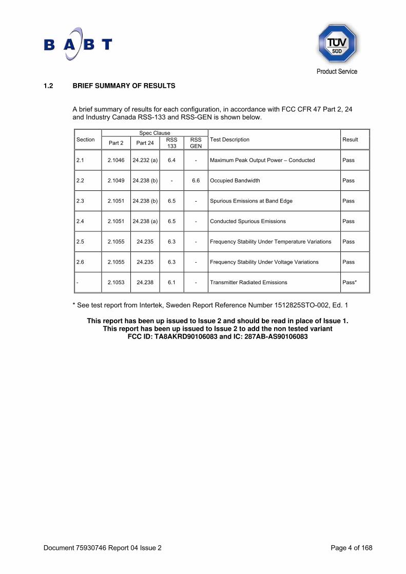
1.2 BRIEF SUMMARY OF RESULTS A brief summary of results for each configuration, in accordance with FCC CFR 47 Part 2, 24 and Industry Canada RSS-133 and RSS-GEN is shown below.
Section Spec Clause
Test Description Result Part 2 Part 24
RSS 133
RSS GEN
2.1 2.1046 24.232 (a) 6.4 - Maximum Peak Output Power – Conducted Pass
2.2 2.1049 24.238 (b) - 6.6 Occupied Bandwidth Pass
2.3 2.1051 24.238 (b) 6.5 - Spurious Emissions at Band Edge Pass
2.4 2.1051 24.238 (a) 6.5 - Conducted Spurious Emissions Pass
2.5 2.1055 24.235 6.3 - Frequency Stability Under Temperature Variations Pass
2.6 2.1055 24.235 6.3 - Frequency Stability Under Voltage Variations Pass
- 2.1053 24.238 6.1 - Transmitter Radiated Emissions Pass*
* See test report from Intertek, Sweden Report Reference Number 1512825STO-002, Ed. 1
This report has been up issued to Issue 2 and should be read in place of Issue 1. This report has been up issued to Issue 2 to add the non tested variant
FCC ID: TA8AKRD90106083 and IC: 287AB-AS90106083
Document 75930746 Report 04 Issue 2 Page 5 of 168
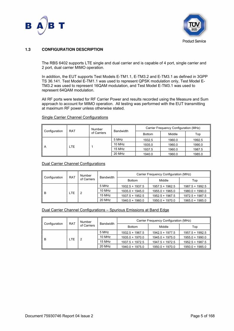
1.3 CONFIGURATION DESCRIPTION The RBS 6402 supports LTE single and dual carrier and is capable of 4 port, single carrier and 2 port, dual carrier MIMO operation. In addition, the EUT supports Test Models E-TM1.1, E-TM3.2 and E-TM3.1 as defined in 3GPP TS 36.141. Test Model E-TM1.1 was used to represent QPSK modulation only, Test Model E-TM3.2 was used to represent 16QAM modulation, and Test Model E-TM3.1 was used to represent 64QAM modulation. All RF ports were tested for RF Carrier Power and results recorded using the Measure and Sum approach to account for MIMO operation. All testing was performed with the EUT transmitting at maximum RF power unless otherwise stated. Single Carrier Channel Configurations
Configuration RAT Number of Carriers
Bandwidth Carrier Frequency Configuration (MHz)
Bottom Middle Top
A LTE 1
5 MHz 1932.5 1960.0 1992.5
10 MHz 1935.0 1960.0 1990.0
15 MHz 1937.5 1960.0 1987.5
20 MHz 1940.0 1960.0 1985.0
Dual Carrier Channel Configurations
Configuration RAT Number of Carriers
Bandwidth Carrier Frequency Configuration (MHz)
Bottom Middle Top
B LTE 2
5 MHz 1932.5 + 1937.5 1957.5 + 1962.5 1987.5 + 1992.5
10 MHz 1935.0 + 1945.0 1955.0 + 1965.0 1980.0 + 1990.0
15 MHz 1937.5 + 1952.5 1952.5 + 1967.5 1972.5 + 1987.5
20 MHz 1940.0 + 1960.0 1950.0 + 1970.0 1965.0 + 1985.0
Dual Carrier Channel Configurations – Spurious Emissions at Band Edge
Configuration RAT Number of Carriers
Bandwidth Carrier Frequency Configuration (MHz)
Bottom Middle Top
B LTE 2
5 MHz 1932.5 + 1967.5 1942.5 + 1977.5 1957.5 + 1992.5
10 MHz 1935.0 + 1970.0 1945.0 + 1975.0 1955.0 + 1990.0
15 MHz 1937.5 + 1972.5 1947.5 + 1972.5 1952.5 + 1987.5
20 MHz 1940.0 + 1975.0 1950.0 + 1970.0 1950.0 + 1985.0
Document 75930746 Report 04 Issue 2 Page 6 of 168
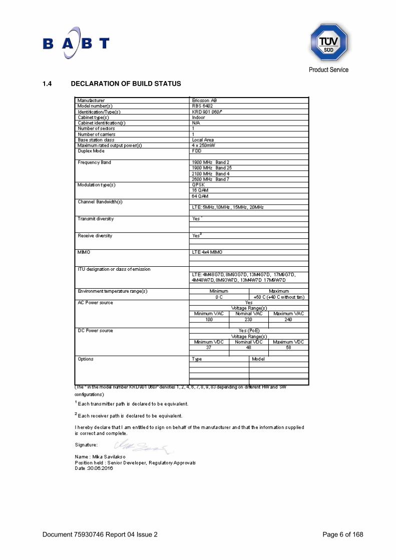
1.4 DECLARATION OF BUILD STATUS
Document 75930746 Report 04 Issue 2 Page 7 of 168
1.5 PRODUCT INFORMATION
1.5.1 Technical Description
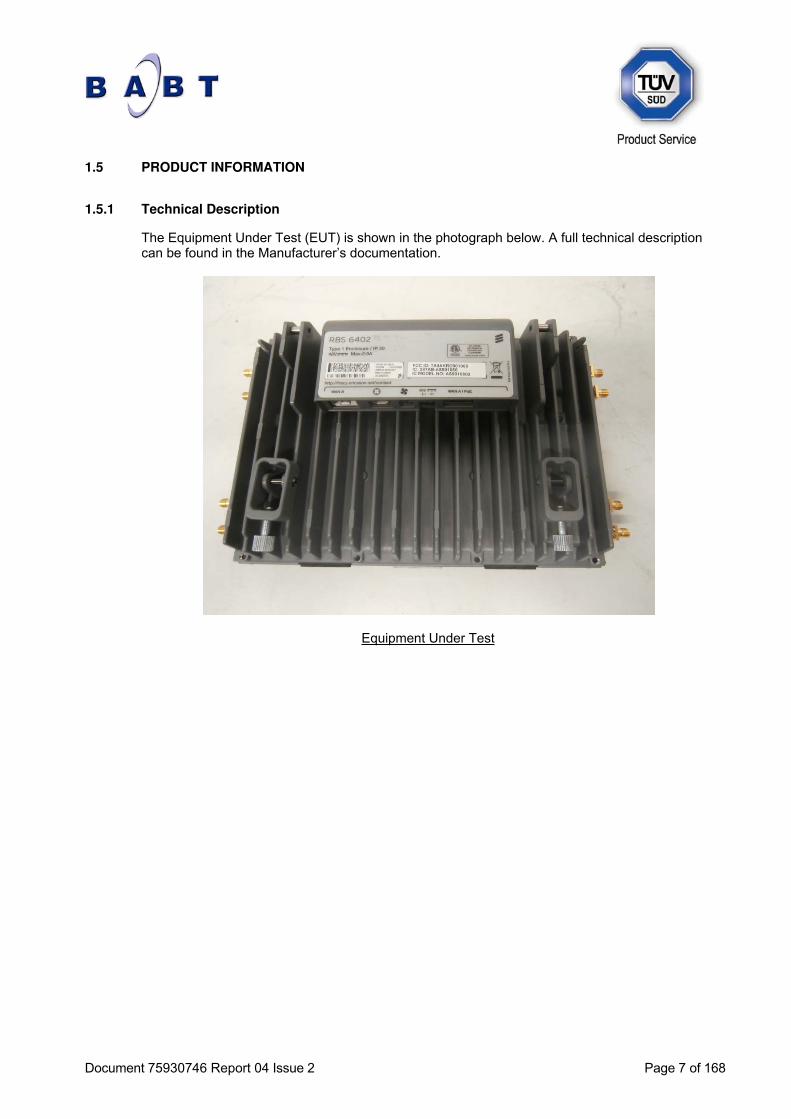
The Equipment Under Test (EUT) is shown in the photograph below. A full technical description can be found in the Manufacturer’s documentation.
Equipment Under Test
Document 75930746 Report 04 Issue 2 Page 8 of 168
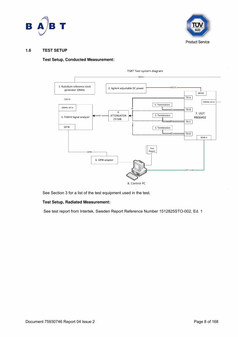
1.6 TEST SETUP Test Setup, Conducted Measurement:
See Section 3 for a list of the test equipment used in the test. Test Setup, Radiated Measurement: See test report from Intertek, Sweden Report Reference Number 1512825STO-002, Ed. 1
Document 75930746 Report 04 Issue 2 Page 9 of 168
1.7 TEST CONDITIONS For all tests the EUT was set up in accordance with the relevant test standard and to represent typical operating conditions. Tests were applied with the EUT situated in a shielded enclosure, test laboratories or a chamber as appropriate. The EUT was powered from a -48V DC supply.
1.8 DEVIATION FROM THE STANDARD No deviations from the applicable test standards or test plan were made during testing.
1.9 MODIFICATION RECORD No modifications were made to the EUT during testing.
1.10 ALTERNATIVE TEST SITE Under our group UKAS Accreditation, TÜV SÜD Product Service conducted the tests at Ericsson in Oulu, Finland.
Document 75930746 Report 04 Issue 2 Page 10 of 168
SECTION 2
TEST DETAILS
Document 75930746 Report 04 Issue 2 Page 11 of 168
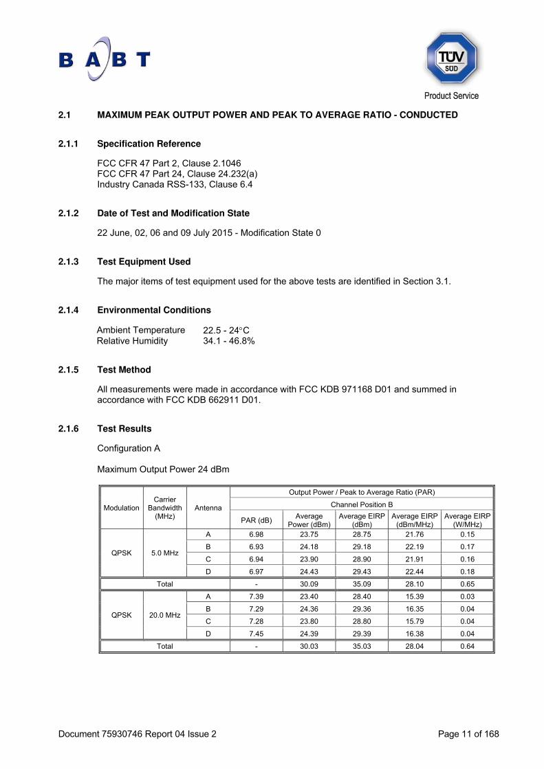
2.1 MAXIMUM PEAK OUTPUT POWER AND PEAK TO AVERAGE RATIO - CONDUCTED
2.1.1 Specification Reference
FCC CFR 47 Part 2, Clause 2.1046 FCC CFR 47 Part 24, Clause 24.232(a) Industry Canada RSS-133, Clause 6.4
2.1.2 Date of Test and Modification State
22 June, 02, 06 and 09 July 2015 - Modification State 0
2.1.3 Test Equipment Used
The major items of test equipment used for the above tests are identified in Section 3.1.
2.1.4 Environmental Conditions
Ambient Temperature 22.5 - 24C Relative Humidity 34.1 - 46.8%
2.1.5 Test Method
All measurements were made in accordance with FCC KDB 971168 D01 and summed in accordance with FCC KDB 662911 D01.
2.1.6 Test Results
Configuration A Maximum Output Power 24 dBm
Modulation Carrier
Bandwidth (MHz)
Antenna
Output Power / Peak to Average Ratio (PAR)
Channel Position B
PAR (dB) Average
Power (dBm) Average EIRP
(dBm) Average EIRP
(dBm/MHz) Average EIRP
(W/MHz)
QPSK 5.0 MHz
A 6.98 23.75 28.75 21.76 0.15
B 6.93 24.18 29.18 22.19 0.17
C 6.94 23.90 28.90 21.91 0.16
D 6.97 24.43 29.43 22.44 0.18
Total - 30.09 35.09 28.10 0.65
QPSK 20.0 MHz
A 7.39 23.40 28.40 15.39 0.03
B 7.29 24.36 29.36 16.35 0.04
C 7.28 23.80 28.80 15.79 0.04
D 7.45 24.39 29.39 16.38 0.04
Total - 30.03 35.03 28.04 0.64

Document 75930746 Report 04 Issue 2 Page 12 of 168
Modulation QPSK - Bandwidth 5.0 MHz - Antenna A - Channel Position B
Modulation QPSK - Bandwidth 5.0 MHz - Antenna B - Channel Position B

Document 75930746 Report 04 Issue 2 Page 13 of 168
Modulation QPSK - Bandwidth 5.0 MHz - Antenna C - Channel Position B
Modulation QPSK - Bandwidth 5.0 MHz - Antenna D - Channel Position B

Document 75930746 Report 04 Issue 2 Page 14 of 168
Modulation QPSK - Bandwidth 20.0 MHz - Antenna A - Channel Position B
Modulation QPSK - Bandwidth 20.0 MHz - Antenna B - Channel Position B

Document 75930746 Report 04 Issue 2 Page 15 of 168
Modulation QPSK - Bandwidth 20.0 MHz - Antenna C - Channel Position B
Modulation QPSK - Bandwidth 20.0 MHz - Antenna D - Channel Position B
Document 75930746 Report 04 Issue 2 Page 16 of 168
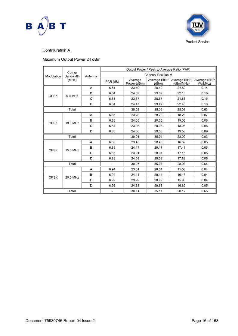
Configuration A Maximum Output Power 24 dBm
Modulation Carrier
Bandwidth (MHz)
Antenna
Output Power / Peak to Average Ratio (PAR)
Channel Position M
PAR (dB) Average
Power (dBm) Average EIRP
(dBm) Average EIRP
(dBm/MHz) Average EIRP
(W/MHz)
QPSK 5.0 MHz
A 6.81 23.49 28.49 21.50 0.14
B 6.84 24.09 29.09 22.10 0.16
C 6.81 23.87 28.87 21.88 0.15
D 6.84 24.47 29.47 22.48 0.18
Total - 30.02 35.02 28.03 0.63
QPSK 10.0 MHz
A 6.85 23.28 28.28 18.28 0.07
B 6.88 24.05 29.05 19.05 0.08
C 6.84 23.95 28.95 18.95 0.08
D 6.85 24.58 29.58 19.58 0.09
Total - 30.01 35.01 28.02 0.63
QPSK 15.0 MHz
A 6.86 23.45 28.45 16.69 0.05
B 6.89 24.17 29.17 17.41 0.06
C 6.87 23.91 28.91 17.15 0.05
D 6.89 24.58 29.58 17.82 0.06
Total - 30.07 35.07 28.08 0.64
QPSK 20.0 MHz
A 6.94 23.51 28.51 15.50 0.04
B 6.94 24.14 29.14 16.13 0.04
C 6.92 23.99 28.99 15.98 0.04
D 6.96 24.63 29.63 16.62 0.05
Total - 30.11 35.11 28.12 0.65

Document 75930746 Report 04 Issue 2 Page 17 of 168
Modulation QPSK - Bandwidth 5.0 MHz - Antenna A - Channel Position M
Modulation QPSK - Bandwidth 5.0 MHz - Antenna B - Channel Position M

Document 75930746 Report 04 Issue 2 Page 18 of 168
Modulation QPSK - Bandwidth 5.0 MHz - Antenna C - Channel Position M
Modulation QPSK - Bandwidth 5.0 MHz - Antenna D - Channel Position M

Document 75930746 Report 04 Issue 2 Page 19 of 168
Modulation QPSK - Bandwidth 10.0 MHz - Antenna A - Channel Position M
Modulation QPSK - Bandwidth 10.0 MHz - Antenna B - Channel Position M

Document 75930746 Report 04 Issue 2 Page 20 of 168
Modulation QPSK - Bandwidth 10.0 MHz - Antenna C - Channel Position M
Modulation QPSK - Bandwidth 10.0 MHz - Antenna D - Channel Position M

Document 75930746 Report 04 Issue 2 Page 21 of 168
Modulation QPSK - Bandwidth 15.0 MHz - Antenna A - Channel Position M
Modulation QPSK - Bandwidth 15.0 MHz - Antenna B - Channel Position M

Document 75930746 Report 04 Issue 2 Page 22 of 168
Modulation QPSK - Bandwidth 15.0 MHz - Antenna C - Channel Position M
Modulation QPSK - Bandwidth 15.0 MHz - Antenna D - Channel Position M

Document 75930746 Report 04 Issue 2 Page 23 of 168
Modulation QPSK - Bandwidth 20.0 MHz - Antenna A - Channel Position M
Modulation QPSK - Bandwidth 20.0 MHz - Antenna B - Channel Position M

Document 75930746 Report 04 Issue 2 Page 24 of 168
Modulation QPSK - Bandwidth 20.0 MHz - Antenna C - Channel Position M
Modulation QPSK - Bandwidth 20.0 MHz - Antenna D - Channel Position M
Document 75930746 Report 04 Issue 2 Page 25 of 168
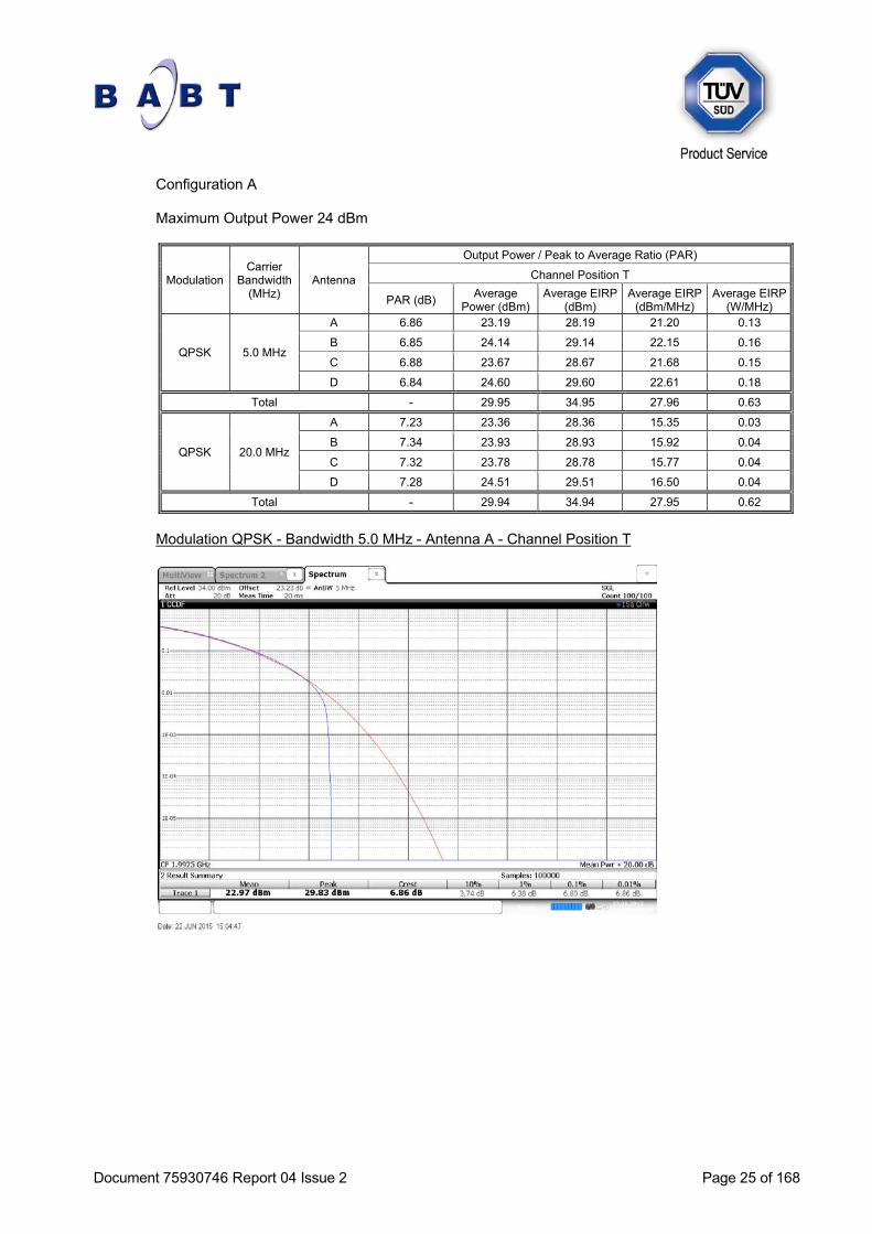
Configuration A Maximum Output Power 24 dBm
Modulation Carrier
Bandwidth (MHz)
Antenna
Output Power / Peak to Average Ratio (PAR)
Channel Position T
PAR (dB) Average
Power (dBm) Average EIRP
(dBm) Average EIRP
(dBm/MHz) Average EIRP
(W/MHz)
QPSK 5.0 MHz
A 6.86 23.19 28.19 21.20 0.13
B 6.85 24.14 29.14 22.15 0.16
C 6.88 23.67 28.67 21.68 0.15
D 6.84 24.60 29.60 22.61 0.18
Total - 29.95 34.95 27.96 0.63
QPSK 20.0 MHz
A 7.23 23.36 28.36 15.35 0.03
B 7.34 23.93 28.93 15.92 0.04
C 7.32 23.78 28.78 15.77 0.04
D 7.28 24.51 29.51 16.50 0.04
Total - 29.94 34.94 27.95 0.62
Modulation QPSK - Bandwidth 5.0 MHz - Antenna A - Channel Position T

Document 75930746 Report 04 Issue 2 Page 26 of 168
Modulation QPSK - Bandwidth 5.0 MHz - Antenna B - Channel Position T
Modulation QPSK - Bandwidth 5.0 MHz - Antenna C - Channel Position T

Document 75930746 Report 04 Issue 2 Page 27 of 168
Modulation QPSK - Bandwidth 5.0 MHz - Antenna D - Channel Position T
Modulation QPSK - Bandwidth 20.0 MHz - Antenna A - Channel Position T

Document 75930746 Report 04 Issue 2 Page 28 of 168
Modulation QPSK - Bandwidth 20.0 MHz - Antenna B - Channel Position T
Modulation QPSK - Bandwidth 20.0 MHz - Antenna C - Channel Position T
Document 75930746 Report 04 Issue 2 Page 29 of 168
Modulation QPSK - Bandwidth 20.0 MHz - Antenna D - Channel Position T
Configuration A Maximum Output Power 24 dBm
Modulation Carrier
Bandwidth (MHz)
Antenna
Output Power / Peak to Average Ratio (PAR)
Channel Position B
PAR (dB) Average
Power (dBm) Average EIRP
(dBm) Average EIRP
(dBm/MHz) Average EIRP
(W/MHz)
16QAM 5.0 MHz
A 6.92 24.10 29.10 22.11 0.16
B 6.92 24.17 29.17 22.18 0.17
C 6.92 23.93 28.93 21.94 0.16
D 6.90 24.49 29.49 22.50 0.18
Total - 30.20 35.20 28.21 0.66
16QAM 20.0 MHz
A 7.44 23.73 28.73 15.72 0.04
B 7.35 24.29 29.29 16.28 0.04
C 7.30 23.87 28.87 15.86 0.04
D 7.41 24.51 29.51 16.50 0.04
Total - 30.13 35.13 28.14 0.65

Document 75930746 Report 04 Issue 2 Page 30 of 168
Modulation 16QAM - Bandwidth 5.0 MHz - Antenna A - Channel Position B
Modulation 16QAM - Bandwidth 5.0 MHz - Antenna B - Channel Position B

Document 75930746 Report 04 Issue 2 Page 31 of 168
Modulation 16QAM - Bandwidth 5.0 MHz - Antenna C - Channel Position B
Modulation 16QAM - Bandwidth 5.0 MHz - Antenna D - Channel Position B

Document 75930746 Report 04 Issue 2 Page 32 of 168
Modulation 16QAM - Bandwidth 20.0 MHz - Antenna A - Channel Position B
Modulation 16QAM - Bandwidth 20.0 MHz - Antenna B - Channel Position B

Document 75930746 Report 04 Issue 2 Page 33 of 168
Modulation 16QAM - Bandwidth 20.0 MHz - Antenna C - Channel Position B
Modulation 16QAM - Bandwidth 20.0 MHz - Antenna D - Channel Position B
Document 75930746 Report 04 Issue 2 Page 34 of 168
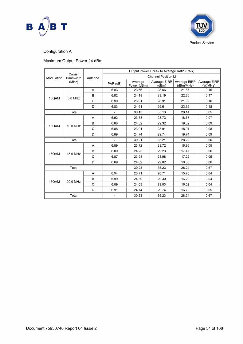
Configuration A Maximum Output Power 24 dBm
Modulation Carrier
Bandwidth (MHz)
Antenna
Output Power / Peak to Average Ratio (PAR)
Channel Position M
PAR (dB) Average
Power (dBm) Average EIRP
(dBm) Average EIRP
(dBm/MHz) Average EIRP
(W/MHz)
16QAM 5.0 MHz
A 6.83 23.66 28.66 21.67 0.15
B 6.82 24.19 29.19 22.20 0.17
C 6.90 23.91 28.91 21.92 0.16
D 6.83 24.61 29.61 22.62 0.18
Total - 30.13 35.13 28.14 0.65
16QAM 10.0 MHz
A 6.92 23.73 28.73 18.73 0.07
B 6.88 24.32 29.32 19.32 0.09
C 6.88 23.91 28.91 18.91 0.08
D 6.89 24.74 29.74 19.74 0.09
Total - 30.21 35.21 28.22 0.66
16QAM 15.0 MHz
A 6.89 23.72 28.72 16.96 0.05
B 6.89 24.23 29.23 17.47 0.06
C 6.87 23.98 28.98 17.22 0.05
D 6.89 24.82 29.82 18.06 0.06
Total - 30.23 35.23 28.24 0.67
16QAM 20.0 MHz
A 6.94 23.71 28.71 15.70 0.04
B 6.99 24.30 29.30 16.29 0.04
C 6.89 24.03 29.03 16.02 0.04
D 6.91 24.74 29.74 16.73 0.05
Total - 30.23 35.23 28.24 0.67

Document 75930746 Report 04 Issue 2 Page 35 of 168
Modulation 16QAM - Bandwidth 5.0 MHz - Antenna A - Channel Position M
Modulation 16QAM - Bandwidth 5.0 MHz - Antenna B - Channel Position M
Document 75930746 Report 04 Issue 2 Page 36 of 168
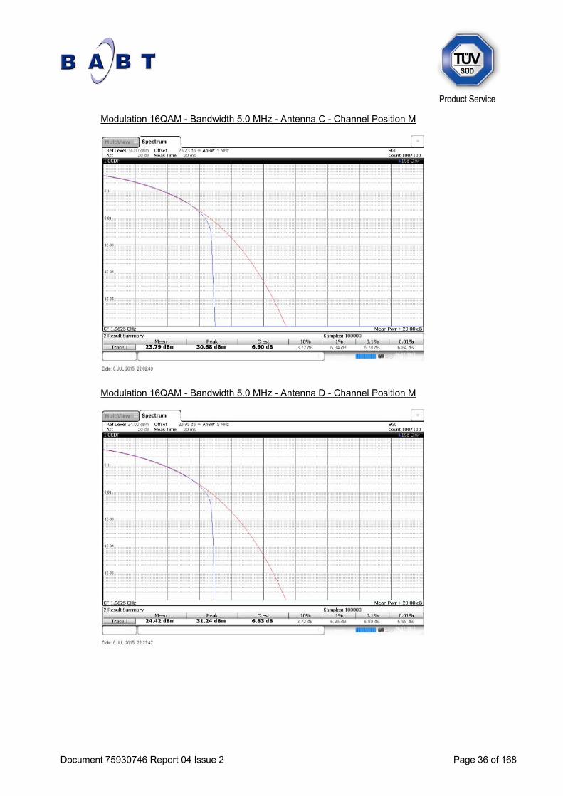
Modulation 16QAM - Bandwidth 5.0 MHz - Antenna C - Channel Position M
Modulation 16QAM - Bandwidth 5.0 MHz - Antenna D - Channel Position M

Document 75930746 Report 04 Issue 2 Page 37 of 168
Modulation 16QAM - Bandwidth 10.0 MHz - Antenna A - Channel Position M
Modulation 16QAM - Bandwidth 10.0 MHz - Antenna B - Channel Position M

Document 75930746 Report 04 Issue 2 Page 38 of 168
Modulation 16QAM - Bandwidth 10.0 MHz - Antenna C - Channel Position M
Modulation 16QAM - Bandwidth 10.0 MHz - Antenna D - Channel Position M

Document 75930746 Report 04 Issue 2 Page 39 of 168
Modulation 16QAM - Bandwidth 15.0 MHz - Antenna A - Channel Position M
Modulation 16QAM - Bandwidth 15.0 MHz - Antenna B - Channel Position M

Document 75930746 Report 04 Issue 2 Page 40 of 168
Modulation 16QAM - Bandwidth 15.0 MHz - Antenna C - Channel Position M
Modulation 16QAM - Bandwidth 15.0 MHz - Antenna D - Channel Position M

Document 75930746 Report 04 Issue 2 Page 41 of 168
Modulation 16QAM - Bandwidth 20.0 MHz - Antenna A - Channel Position M
Modulation 16QAM - Bandwidth 20.0 MHz - Antenna B - Channel Position M

Document 75930746 Report 04 Issue 2 Page 42 of 168
Modulation 16QAM - Bandwidth 20.0 MHz - Antenna C - Channel Position M
Modulation 16QAM - Bandwidth 20.0 MHz - Antenna D - Channel Position M
Document 75930746 Report 04 Issue 2 Page 43 of 168
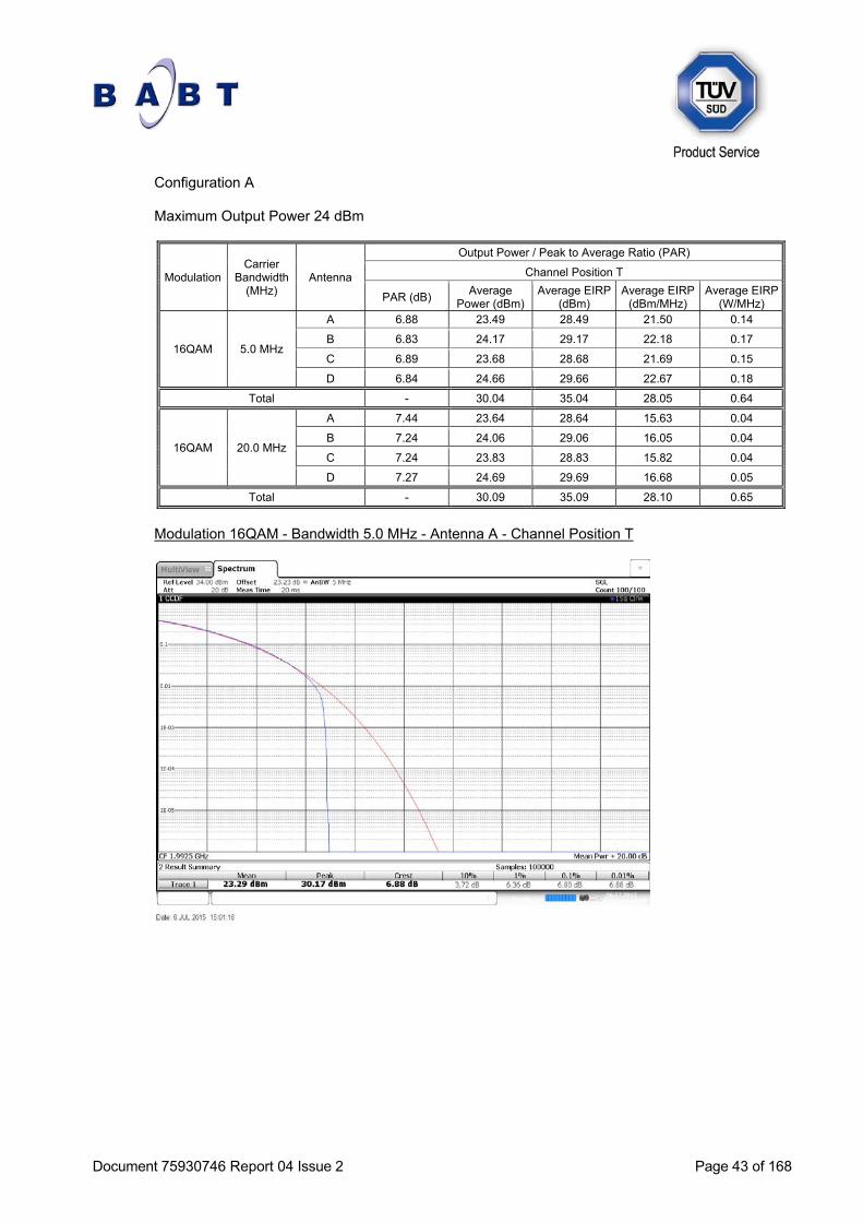
Configuration A Maximum Output Power 24 dBm
Modulation Carrier
Bandwidth (MHz)
Antenna
Output Power / Peak to Average Ratio (PAR)
Channel Position T
PAR (dB) Average
Power (dBm) Average EIRP
(dBm) Average EIRP
(dBm/MHz) Average EIRP
(W/MHz)
16QAM 5.0 MHz
A 6.88 23.49 28.49 21.50 0.14
B 6.83 24.17 29.17 22.18 0.17
C 6.89 23.68 28.68 21.69 0.15
D 6.84 24.66 29.66 22.67 0.18
Total - 30.04 35.04 28.05 0.64
16QAM 20.0 MHz
A 7.44 23.64 28.64 15.63 0.04
B 7.24 24.06 29.06 16.05 0.04
C 7.24 23.83 28.83 15.82 0.04
D 7.27 24.69 29.69 16.68 0.05
Total - 30.09 35.09 28.10 0.65
Modulation 16QAM - Bandwidth 5.0 MHz - Antenna A - Channel Position T

Document 75930746 Report 04 Issue 2 Page 44 of 168
Modulation 16QAM - Bandwidth 5.0 MHz - Antenna B - Channel Position T
Modulation 16QAM - Bandwidth 5.0 MHz - Antenna C - Channel Position T

Document 75930746 Report 04 Issue 2 Page 45 of 168
Modulation 16QAM - Bandwidth 5.0 MHz - Antenna D - Channel Position T
Modulation 16QAM - Bandwidth 20.0 MHz - Antenna A - Channel Position T

Document 75930746 Report 04 Issue 2 Page 46 of 168
Modulation 16QAM - Bandwidth 20.0 MHz - Antenna B - Channel Position T
Modulation 16QAM - Bandwidth 20.0 MHz - Antenna C - Channel Position T
Document 75930746 Report 04 Issue 2 Page 47 of 168
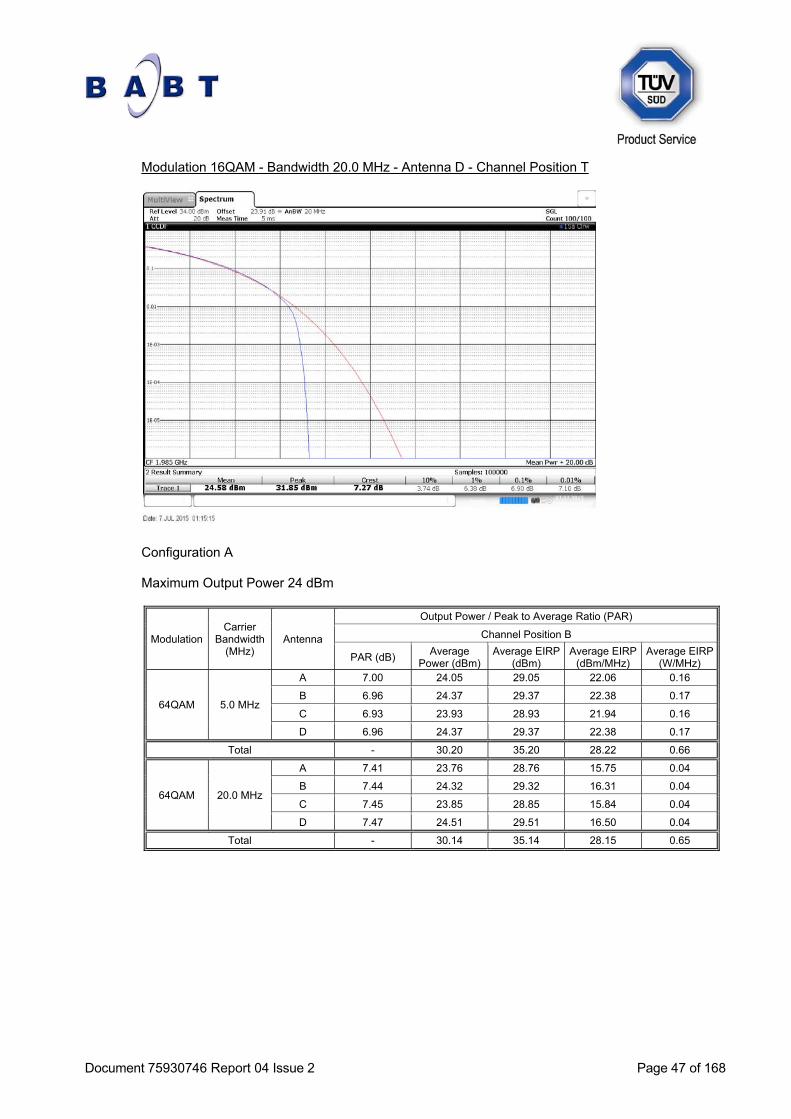
Modulation 16QAM - Bandwidth 20.0 MHz - Antenna D - Channel Position T
Configuration A Maximum Output Power 24 dBm
Modulation Carrier
Bandwidth (MHz)
Antenna
Output Power / Peak to Average Ratio (PAR)
Channel Position B
PAR (dB) Average
Power (dBm) Average EIRP
(dBm) Average EIRP
(dBm/MHz) Average EIRP
(W/MHz)
64QAM 5.0 MHz
A 7.00 24.05 29.05 22.06 0.16
B 6.96 24.37 29.37 22.38 0.17
C 6.93 23.93 28.93 21.94 0.16
D 6.96 24.37 29.37 22.38 0.17
Total - 30.20 35.20 28.22 0.66
64QAM 20.0 MHz
A 7.41 23.76 28.76 15.75 0.04
B 7.44 24.32 29.32 16.31 0.04
C 7.45 23.85 28.85 15.84 0.04
D 7.47 24.51 29.51 16.50 0.04
Total - 30.14 35.14 28.15 0.65

Document 75930746 Report 04 Issue 2 Page 48 of 168
Modulation 64QAM - Bandwidth 5.0 MHz - Antenna A - Channel Position B
Modulation 64QAM - Bandwidth 5.0 MHz - Antenna B - Channel Position B

Document 75930746 Report 04 Issue 2 Page 49 of 168
Modulation 64QAM - Bandwidth 5.0 MHz - Antenna C - Channel Position B
Modulation 64QAM - Bandwidth 5.0 MHz - Antenna D - Channel Position B

Document 75930746 Report 04 Issue 2 Page 50 of 168
Modulation 64QAM - Bandwidth 20.0 MHz - Antenna A - Channel Position B
Modulation 64QAM - Bandwidth 20.0 MHz - Antenna B - Channel Position B

Document 75930746 Report 04 Issue 2 Page 51 of 168
Modulation 64QAM - Bandwidth 20.0 MHz - Antenna C - Channel Position B
Modulation 64QAM - Bandwidth 20.0 MHz - Antenna D - Channel Position B
Document 75930746 Report 04 Issue 2 Page 52 of 168
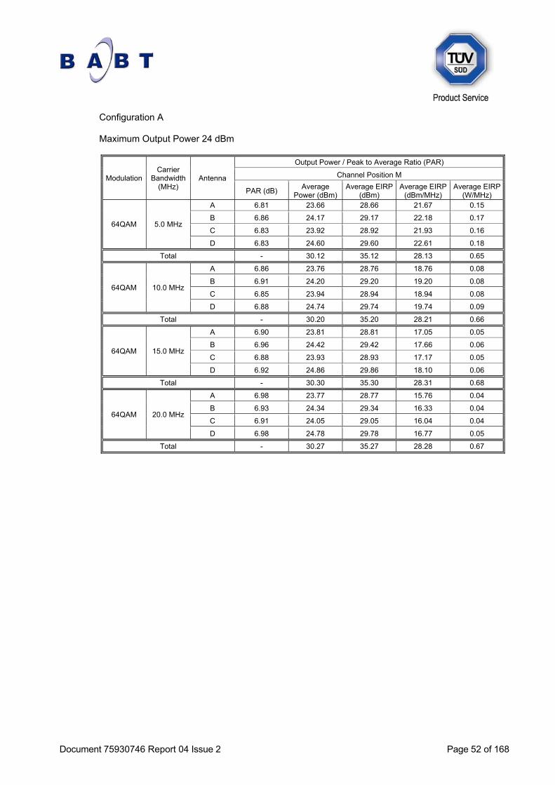
Configuration A Maximum Output Power 24 dBm
Modulation Carrier
Bandwidth (MHz)
Antenna
Output Power / Peak to Average Ratio (PAR)
Channel Position M
PAR (dB) Average
Power (dBm) Average EIRP
(dBm) Average EIRP
(dBm/MHz) Average EIRP
(W/MHz)
64QAM 5.0 MHz
A 6.81 23.66 28.66 21.67 0.15
B 6.86 24.17 29.17 22.18 0.17
C 6.83 23.92 28.92 21.93 0.16
D 6.83 24.60 29.60 22.61 0.18
Total - 30.12 35.12 28.13 0.65
64QAM 10.0 MHz
A 6.86 23.76 28.76 18.76 0.08
B 6.91 24.20 29.20 19.20 0.08
C 6.85 23.94 28.94 18.94 0.08
D 6.88 24.74 29.74 19.74 0.09
Total - 30.20 35.20 28.21 0.66
64QAM 15.0 MHz
A 6.90 23.81 28.81 17.05 0.05
B 6.96 24.42 29.42 17.66 0.06
C 6.88 23.93 28.93 17.17 0.05
D 6.92 24.86 29.86 18.10 0.06
Total - 30.30 35.30 28.31 0.68
64QAM 20.0 MHz
A 6.98 23.77 28.77 15.76 0.04
B 6.93 24.34 29.34 16.33 0.04
C 6.91 24.05 29.05 16.04 0.04
D 6.98 24.78 29.78 16.77 0.05
Total - 30.27 35.27 28.28 0.67

![Abstract - COREfracture mechanics based properties of materials at impact rates [1,2]. The more common use of these instrumented impact tests on polymers has resulted in ISO 17281](https://img.pdfslide.us/doc/110x75/5e5ac5af54cb8a63f60ae4cf/abstract-core-fracture-mechanics-based-properties-of-materials-at-impact-rates.jpg)