Embed Size (px)
Citation preview
MAINTAINABILITY OF FACILITIES - For Building Professionals© World Scientific Publishing Co. Pte. Ltd.http://www.worldscibooks.com/architecture/7566.html
CHAPTER 2
WET AREA
2.1. General
One of the building elements that demands high attention is internal wetareas. Internal wet areas are areas subjected to constant damp conditionswith alternating drying and wetting cycles. Although wet areas may onlyoccupy less than 10% of the gross floor area, the annual maintenance costfor wet area can range from 35% to 50% of the total maintenance costdepending on the type of facility [1].
Various systems and components such as waterproofing membrane,screed, architectural finishes, service pipes and sanitary fittings are usedin wet areas. In-situ construction and pre-cast technology have beenadopted to construct these units. These systems and components are madeup of numerous sub-components whose performances are depended onfor the overall structural, functional and aesthetic performance of thewhole system. The failure of any component may result in subsequentdefects surfacing in other components and ultimately bringing about thetotal failure of the entire wet area. It is hence crucial for the design, con-struction and maintenance of all components to be carried out soundly andwith due considerations to the likely impacts they would have on eachother and on the overall performance of the system [2].
2.2. Systems and Components Selection
The selection of primary components and systems such as waterproofingsystem, screed, tile and tile bedding, grout, paint and service pipesare mainly based on their serviceability so that they may continue to per-form their intended functions through their design life. Durability of these
FA
21
b885_Chapter-02.qxd 12/29/2009 2:34 PM Page 21
MAINTAINABILITY OF FACILITIES - For Building Professionals© World Scientific Publishing Co. Pte. Ltd.http://www.worldscibooks.com/architecture/7566.html
components should be checked under the real exposure conditions in wetareas. Compatibility among components is crucial.
Details of material durability, property etc. can be found in the“Material Manual” of the Maintainability Website (http://www.hpbc.bdg.nus.edu.sg/).
2.2.1. Waterproofing System
Waterproofing systems are applied over the substrates of wet area floorsand walls to improve the water-tightness of the wet area units. Water-tightness of wet areas relies mainly on the adequacy of waterproofing overpenetrations, projections and joints and how these discontinuities of thefloor and wall elements can achieve a “monolithic” structure. The deci-sion to select a specific waterproofing system should take intoconsideration the design of the substrate structure and area of coverage.
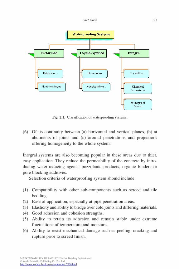
Generally, waterproofing systems can be classified into three types [3]:
(1) preformed membrane,(2) liquid-applied membrane, and(3) integral systems
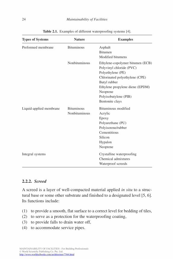
Figure 2.1 shows the various classifications of waterproofing systems ofpreformed, liquid-applied and integral systems. Typical examples aregiven in Table 2.1.
Preformed membrane is often used for large areas such as roofs andbasements. Liquid-applied membrane is popular for small areas such aswet areas because:
(1) The membrane is seamless (no physical joints).(2) The membrane has good elongation and recovery properties to
accommodate substrate movements and to bridge cracks.(3) Of its unique built-in primer, it provides positive adhesion to both
base substrate and top wearing (screed) surface (i.e. screed can beapplied directly on membrane without debonding).
(4) Of its even adhesion to every part of the substrate.(5) It offers the flexibility of applying over the substrate.
FA
22 Maintainability of Facilities
b885_Chapter-02.qxd 12/29/2009 2:34 PM Page 22
MAINTAINABILITY OF FACILITIES - For Building Professionals© World Scientific Publishing Co. Pte. Ltd.http://www.worldscibooks.com/architecture/7566.html
(6) Of its continuity between (a) horizontal and vertical planes, (b) atabutments of joints and (c) around penetrations and projectionsoffering homogeneity to the whole system.
Integral systems are also becoming popular in these areas due to thier,easy application. They reduce the permeability of the concrete by intro-ducing water-reducing agents, pozzolanic products, organic binders orpore blocking additives.
Selection criteria of waterproofing system should include:
(1) Compatibility with other sub-components such as screed and tilebedding.
(2) Ease of application, especially at pipe penetration areas.(3) Elasticity and ability to bridge over cold joints and differing materials.(4) Good adhesion and cohesion strengths.(5) Ability to retain its adhesion and remain stable under extreme
fluctuations of temperature and moisture.(6) Ability to resist mechanical damage such as peeling, cracking and
rupture prior to screed finish.
FA
Wet Area 23
Fig. 2.1. Classification of waterproofing systems.
b885_Chapter-02.qxd 12/29/2009 2:34 PM Page 23
MAINTAINABILITY OF FACILITIES - For Building Professionals© World Scientific Publishing Co. Pte. Ltd.http://www.worldscibooks.com/architecture/7566.html
2.2.2. Screed
A screed is a layer of well-compacted material applied in situ to a struc-tural base or some other substrate and finished to a designated level [5, 6].Its functions include:
(1) to provide a smooth, flat surface to a correct level for bedding of tiles,(2) to serve as a protection for the waterproofing coating,(3) to provide falls to drain water off,(4) to accommodate service pipes.
FA
24 Maintainability of Facilities
Table 2.1. Examples of different waterproofing systems [4].
Types of Systems Nature Examples
Preformed membrane Bituminous AsphaltBitumenModified bitumens
Nonbituminous Ethylene-copolymer bitumen (ECB)Polyvinyl chloride (PVC)Polyethylene (PE)Chlorinated polyethylene (CPE)Butyl rubberEthylene propylene diene (EPDM)NeoprenePolyisobutylene (PIB)Bentonite clays
Liquid-applied membrane Bituminous Bituminous modifiedNonbituminous Acrylic
EpoxyPolyurethane (PU)Polyisorene/rubberCementitiousSiliconHypalonNeoprene
Integral systems Crystalline waterproofingChemical admixturesWaterproof screeds
b885_Chapter-02.qxd 12/29/2009 2:34 PM Page 24
MAINTAINABILITY OF FACILITIES - For Building Professionals© World Scientific Publishing Co. Pte. Ltd.http://www.worldscibooks.com/architecture/7566.html
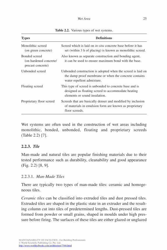
Wet systems are often used in the construction of wet areas includingmonolithic, bonded, unbonded, floating and proprietary screeds(Table 2.2) [7].
2.2.3. Tile
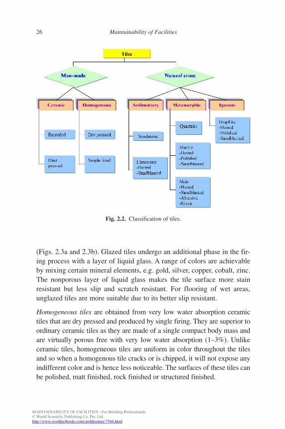
Man-made and natural tiles are popular finishing materials due to theirtested performance such as durability, cleanability and good appearance(Fig. 2.2) [8, 9].
2.2.3.1. Man-Made Tiles
There are typically two types of man-made tiles: ceramic and homoge-neous tiles.
Ceramic tiles can be classified into extruded tiles and dust pressed tiles.Extruded tiles are shaped in the plastic state in an extruder and the result-ing column cut into tiles of predetermined lengths. Dust-pressed tiles areformed from powder or small grains, shaped in moulds under high pres-sure before firing. The surfaces of these tiles are either glazed or unglazed
FA
Wet Area 25
Table 2.2. Various types of wet systems.
Types Definitions
Monolithic screed Screed which is laid on in-situ concrete base before it has(on green concrete) set (within 3 h of placing) is known as monolithic screed.
Bonded screed Also known as separate construction and bonding agent,(on hardened concrete/ it can be used to ensure maximum bond with the base.precast concrete)
Unbonded screed Unbonded construction is adopted when the screed is laid onthe damp proof membrane or when the concrete containswater repellent admixture.
Floating screed This type of screed is unbonded to concrete base and isdesigned as floating screed to accommodate heatingelements or sound insulation.
Proprietary floor screed Screeds that are basically denser and modified by inclusionof materials in emulsion form are known as proprietaryfloor screeds.
b885_Chapter-02.qxd 12/29/2009 2:34 PM Page 25
MAINTAINABILITY OF FACILITIES - For Building Professionals© World Scientific Publishing Co. Pte. Ltd.http://www.worldscibooks.com/architecture/7566.html
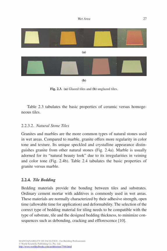
(Figs. 2.3a and 2.3b). Glazed tiles undergo an additional phase in the fir-ing process with a layer of liquid glass. A range of colors are achievableby mixing certain mineral elements, e.g. gold, silver, copper, cobalt, zinc.The nonporous layer of liquid glass makes the tile surface more stainresistant but less slip and scratch resistant. For flooring of wet areas,unglazed tiles are more suitable due to its better slip resistant.
Homogeneous tiles are obtained from very low water absorption ceramictiles that are dry pressed and produced by single firing. They are superior toordinary ceramic tiles as they are made of a single compact body mass andare virtually porous free with very low water absorption (1–3%). Unlikeceramic tiles, homogeneous tiles are uniform in color throughout the tilesand so when a homogenous tile cracks or is chipped, it will not expose anyindifferent color and is hence less noticeable. The surfaces of these tiles canbe polished, matt finished, rock finished or structured finished.
FA
26 Maintainability of Facilities
Fig. 2.2. Classification of tiles.
b885_Chapter-02.qxd 12/29/2009 2:34 PM Page 26
MAINTAINABILITY OF FACILITIES - For Building Professionals© World Scientific Publishing Co. Pte. Ltd.http://www.worldscibooks.com/architecture/7566.html
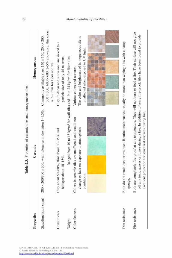
Table 2.3 tabulates the basic properties of ceramic versus homoge-neous tiles.
2.2.3.2. Natural Stone Tiles
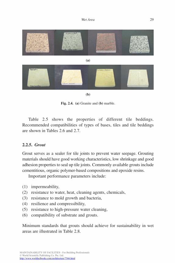
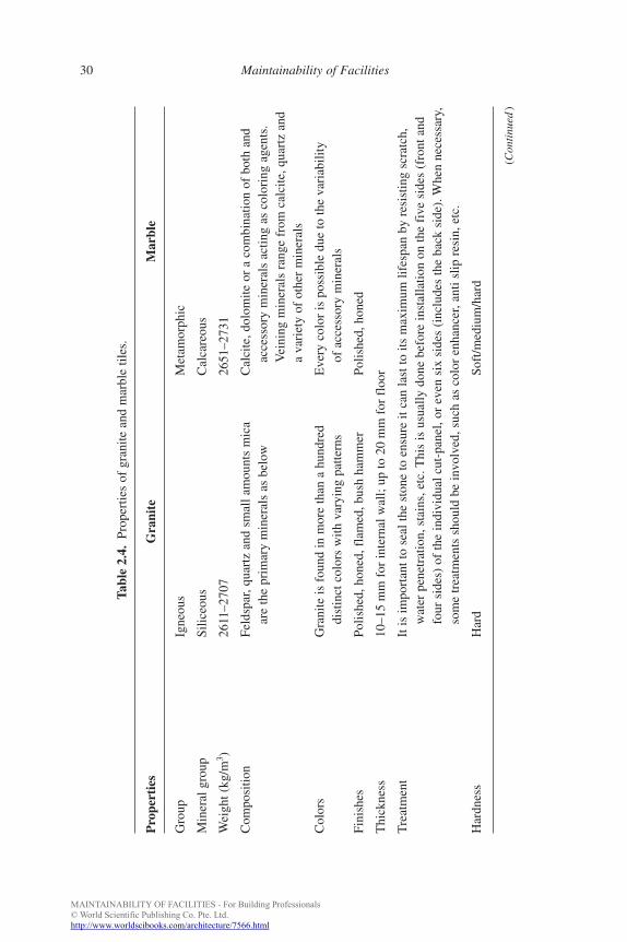
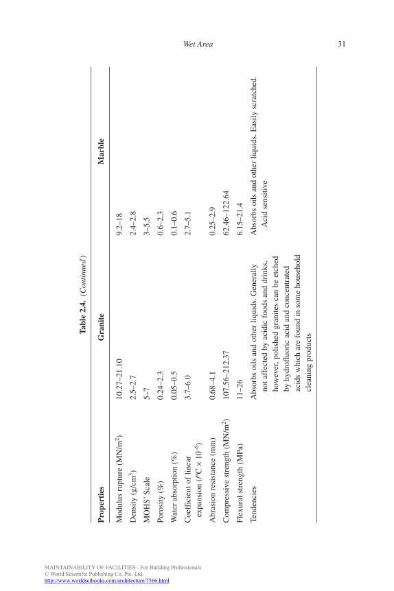
Granites and marbles are the more common types of natural stones usedin wet areas. Compared to marble, granite offers more regularity in colortone and texture. Its unique speckled and crystalline appearance distin-guishes granite from other natural stones (Fig. 2.4a). Marble is usuallyadorned for its “natural beauty look” due to its irregularities in veiningand color tone (Fig. 2.4b). Table 2.4 tabulates the basic properties ofgranite versus marble.
2.2.4. Tile Bedding
Bedding materials provide the bonding between tiles and substrates.Ordinary cement mortar with additives is commonly used in wet areas.These materials are normally characterized by their adhesive strength, opentime (allowable time for application) and deformability. The selection of thecorrect type of bedding material for tiling needs to be compatible with thetype of substrate, tile and the designed bedding thickness, to minimize con-sequences such as debonding, cracking and efflorescence [10].
FA
Wet Area 27
Fig. 2.3. (a) Glazed tiles and (b) unglazed tiles.
(b)
(a)
b885_Chapter-02.qxd 12/29/2009 2:34 PM Page 27
MAINTAINABILITY OF FACILITIES - For Building Professionals© World Scientific Publishing Co. Pte. Ltd.http://www.worldscibooks.com/architecture/7566.html
FA
28 Maintainability of Facilities
Tabl
e 2.
3.Pr
oper
ties
of c
eram
ic ti
les
and
hom
ogen
eous
tile
s.
Pro
pert
ies
Cer
amic
Hom
ogen
eous
Size
/dim
ensi
on (
mm
)20
0×
200/
300
×30
0, w
ith to
lera
nce
in d
evia
tion
1–1.
5%.
Com
mon
ly a
vaila
ble
size
: 150
×15
0, 2
00×
200,
300
×30
0, 6
00×
600,
2–5
% a
llow
ance
, thi
ckne
ss
is 7
–9 m
m f
or f
loor
and
wal
l.
Con
stitu
ents
Cla
y ab
out 5
0–60
%, f
lint a
bout
30–
35%
and
C
lay,
fel
dspa
r an
d si
lica
sand
are
sie
ved
to a
feld
spar
abo
ut 1
0–15
%.
part
icle
siz
e of
onl
y 45
mic
rons
.
Wei
ght
Ran
ged
from
10
to 1
5kg
/m2
for
wal
l tile
s an
d 19
to 2
4kg
/m2
for
floo
r til
es.
Col
or f
astn
ess
Col
ors
in c
eram
ic ti
les
are
unaf
fect
ed a
nd w
ould
not
V
ario
us c
olor
s an
d te
xtur
es.
chan
ge o
r fa
de o
n ex
posu
re to
atm
osph
eric
T
he c
olor
and
bri
ghtn
ess
of h
omog
eneo
us ti
le is
cond
ition
s.un
affe
cted
whe
n ex
pose
d to
UV
light
.
Dir
t res
ista
nce
Bot
h do
not
ret
ain
dust
or
resi
dues
. Rou
tine
mai
nten
ance
, usu
ally
no
mor
e th
an w
ipin
g til
es w
ith a
dam
psp
onge
.
Fire
res
ista
nce
Bot
h ar
e co
mpl
etel
y fi
re-p
roof
at a
ny te
mpe
ratu
re. T
hey
will
not
bur
n or
fee
d a
fire
. The
ir s
urfa
ce w
ill n
ot g
ive
off
any
toxi
c ga
sses
or
fum
es d
urin
g a
fire
. In
addi
tion
to b
eing
fir
e-pr
oof,
tile
s ha
ve b
een
foun
d to
pro
vide
exce
llent
pro
tect
ion
for
stru
ctur
al s
urfa
ces
duri
ng f
ire.
b885_Chapter-02.qxd 12/29/2009 2:34 PM Page 28
MAINTAINABILITY OF FACILITIES - For Building Professionals© World Scientific Publishing Co. Pte. Ltd.http://www.worldscibooks.com/architecture/7566.html
FA
Wet Area 29
(b)
(a)
Fig. 2.4. (a) Granite and (b) marble.
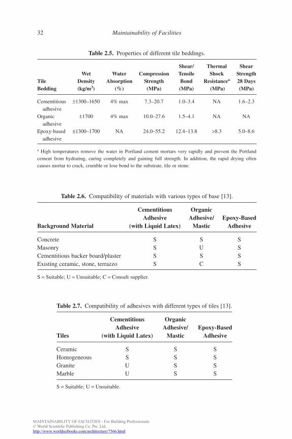
Table 2.5 shows the properties of different tile beddings.Recommended compatibilities of types of bases, tiles and tile beddingsare shown in Tables 2.6 and 2.7.
2.2.5. Grout
Grout serves as a sealer for tile joints to prevent water seepage. Groutingmaterials should have good working characteristics, low shrinkage and goodadhesion properties to seal up tile joints. Commonly available grouts includecementitious, organic polymer-based compositions and epoxide resins.
Important performance parameters include:
(1) impermeability,(2) resistance to water, heat, cleaning agents, chemicals,(3) resistance to mold growth and bacteria,(4) resilience and compressibility,(5) resistance to high-pressure water cleaning,(6) compatibility of substrate and grouts.
Minimum standards that grouts should achieve for sustainability in wetareas are illustrated in Table 2.8.
b885_Chapter-02.qxd 12/29/2009 2:34 PM Page 29
MAINTAINABILITY OF FACILITIES - For Building Professionals© World Scientific Publishing Co. Pte. Ltd.http://www.worldscibooks.com/architecture/7566.html
FA
30 Maintainability of Facilities
Tabl
e 2.
4.Pr
oper
ties
of g
rani
te a
nd m
arbl
e til
es.
Pro
pert
ies
Gra
nite
Mar
ble
Gro
upIg
neou
sM
etam
orph
ic
Min
eral
gro
upSi
liceo
usC
alca
reou
s
Wei
ght (
kg/m
3 )26
11–2
707
2651
–273
1
Com
posi
tion
Feld
spar
, qua
rtz
and
smal
l am
ount
s m
ica
Cal
cite
, dol
omite
or
a co
mbi
natio
n of
bot
h an
d ar
e th
e pr
imar
y m
iner
als
as b
elow
acce
ssor
y m
iner
als
actin
g as
col
orin
g ag
ents
.V
eini
ng m
iner
als
rang
e fr
om c
alci
te, q
uart
z an
d a
vari
ety
of o
ther
min
eral
s
Col
ors
Gra
nite
is f
ound
in m
ore
than
a h
undr
ed
Eve
ry c
olor
is p
ossi
ble
due
to th
e va
riab
ility
dist
inct
col
ors
with
var
ying
pat
tern
sof
acc
esso
ry m
iner
als
Fini
shes
Po
lishe
d, h
oned
, fla
med
, bus
h ha
mm
erPo
lishe
d, h
oned
Thi
ckne
ss
10–1
5m
m f
or in
tern
al w
all;
up to
20
mm
for
flo
or
Tre
atm
ent
It is
impo
rtan
t to
seal
the
ston
e to
ens
ure
it ca
n la
st to
its
max
imum
life
span
by
resi
stin
g sc
ratc
h,w
ater
pen
etra
tion,
sta
ins,
etc
. Thi
s is
usu
ally
don
e be
fore
inst
alla
tion
on th
e fi
ve s
ides
(fr
ont a
ndfo
ur s
ides
) of
the
indi
vidu
al c
ut-p
anel
, or
even
six
sid
es (
incl
udes
the
back
sid
e). W
hen
nece
ssar
y,so
me
trea
tmen
ts s
houl
d be
invo
lved
, suc
h as
col
or e
nhan
cer,
anti
slip
res
in, e
tc.
Har
dnes
s H
ard
Soft
/med
ium
/har
d
(Con
tinu
ed)
b885_Chapter-02.qxd 12/29/2009 2:34 PM Page 30
MAINTAINABILITY OF FACILITIES - For Building Professionals© World Scientific Publishing Co. Pte. Ltd.http://www.worldscibooks.com/architecture/7566.html
FA
Wet Area 31
Tabl
e 2.
4.(C
onti
nued
)
Pro
pert
ies
Gra
nite
Mar
ble
Mod
ulus
rup
ture
(M
N/m
2 )10
.27–
21.1
0 9.
2–18
Den
sity
(g/
cm3 )
2.5–
2.7
2.4–
2.8
MO
HS’
Scal
e5–
73–
5.5
Poro
sity
(%
)0.
24–2
.30.
6–2.
3
Wat
er a
bsor
ptio
n (%
)0.
05–0
.5
0.1–
0.6
Coe
ffic
ient
of
linea
r3.
7–6.
0 2.
7–5.
1ex
pans
ion
(/ºC
×10
–6)
Abr
asio
n re
sist
ance
(m
m)
0.68
–4.1
0.
25–2
.9
Com
pres
sive
str
engt
h (M
N/m
2 )10
7.56
–212
.37
62.4
6–12
2.64
Flex
ural
str
engt
h (M
Pa)
11–2
6 6.
15–2
1.4
Tend
enci
es
Abs
orbs
oils
and
oth
er li
quid
s. G
ener
ally
Abs
orbs
oils
and
oth
er li
quid
s. E
asily
scr
atch
ed.
not a
ffec
ted
by a
cidi
c fo
ods
and
drin
ks,
Aci
d se
nsiti
veho
wev
er, p
olis
hed
gran
ites
can
be e
tche
dby
hyd
rofl
uori
c ac
id a
nd c
once
ntra
ted
acid
s w
hich
are
fou
nd in
som
e ho
useh
old
clea
ning
pro
duct
s
b885_Chapter-02.qxd 12/29/2009 2:34 PM Page 31
MAINTAINABILITY OF FACILITIES - For Building Professionals© World Scientific Publishing Co. Pte. Ltd.http://www.worldscibooks.com/architecture/7566.html
FA
32 Maintainability of Facilities
Table 2.7. Compatibility of adhesives with different types of tiles [13].
Cementitious OrganicAdhesive Adhesive/ Epoxy-Based
Tiles (with Liquid Latex) Mastic Adhesive
Ceramic S S SHomogeneous S S SGranite U S SMarble U S S
S = Suitable; U = Unsuitable.
Table 2.5. Properties of different tile beddings.
Shear/ Thermal ShearWet Water Compression Tensile Shock Strength
Tile Density Absorption Strength Bond Resistancea 28 DaysBedding (kg/m3) (%) (MPa) (MPa) (MPa) (MPa)
Cementitious ±1300–1650 4% max 7.3–20.7 1.0–3.4 NA 1.6–2.3adhesive
Organic ±1700 4% max 10.0–27.6 1.5–4.1 NA NAadhesive
Epoxy-based ±1300–1700 NA 24.0–55.2 12.4–13.8 >8.3 5.0–8.6adhesive
a High temperatures remove the water in Portland cement mortars very rapidly and prevent the Portland
cement from hydrating, curing completely and gaining full strength. In addition, the rapid drying often
causes mortar to crack, crumble or lose bond to the substrate, tile or stone.
Table 2.6. Compatibility of materials with various types of base [13].
Cementitious OrganicAdhesive Adhesive/ Epoxy-Based
Background Material (with Liquid Latex) Mastic Adhesive
Concrete S S SMasonry S U SCementitious backer board/plaster S S SExisting ceramic, stone, terrazzo S C S
S = Suitable; U = Unsuitable; C = Consult supplier.
b885_Chapter-02.qxd 12/29/2009 2:34 PM Page 32
MAINTAINABILITY OF FACILITIES - For Building Professionals© World Scientific Publishing Co. Pte. Ltd.http://www.worldscibooks.com/architecture/7566.html
FA
Wet Area 33
2.2.6. Paint
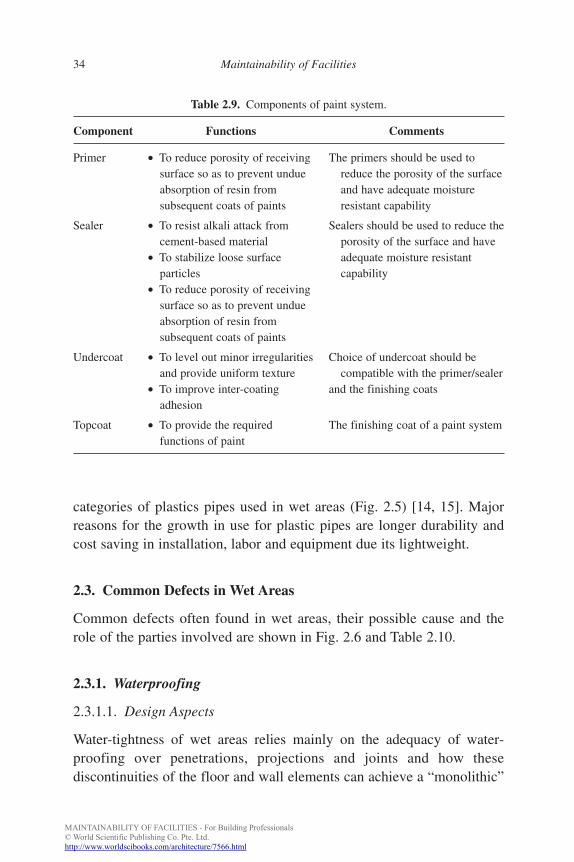
Paints serve as decorative and protective coatings over ceilings andportions of the un-tiled walls in wet areas. A typical paint system is com-posed of primer, sealer, undercoat and topcoat (Table 2.9). Appropriateselection of paint is important as the paint film is subjected to constantmoist conditions in wet areas. Common defects include peeling, flaking,blistering, biological attack and efflorescence.
For long-term performance, the selection should hence consider:
(1) type of substrate,(2) type of environment,(3) application method,(4) surface preparation,(5) overcoating interval.
2.2.7. Service Pipe
Cast iron and plastic pipes have traditionally been used in internal wetareas of high-rise buildings. Due to the poor performance of cast ironunder high humidity conditions, with corrosion and subsequent waterleakage as common maintenance problems [12, 13], they are not used innew constructions of wet areas. Plastic materials are therefore recom-mended for long-term performance of the plumbing system. Chlorinatedpolyvinyl-chloride (cPVC) and polyvinyl chloride (PVC) are the main
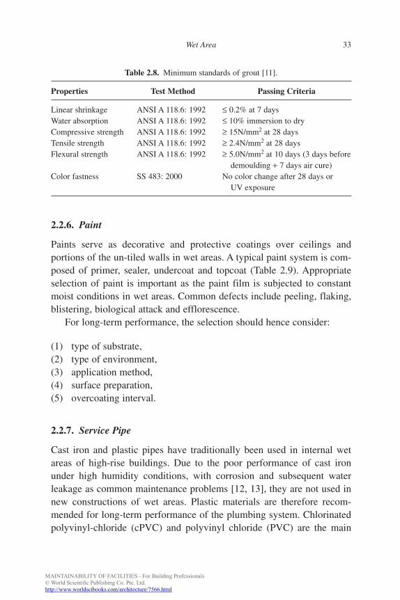
Table 2.8. Minimum standards of grout [11].
Properties Test Method Passing Criteria
Linear shrinkage ANSI A 118.6: 1992 ≤ 0.2% at 7 daysWater absorption ANSI A 118.6: 1992 ≤ 10% immersion to dryCompressive strength ANSI A 118.6: 1992 ≥ 15N/mm2 at 28 daysTensile strength ANSI A 118.6: 1992 ≥ 2.4N/mm2 at 28 daysFlexural strength ANSI A 118.6: 1992 ≥ 5.0N/mm2 at 10 days (3 days before
demoulding + 7 days air cure)Color fastness SS 483: 2000 No color change after 28 days or
UV exposure
b885_Chapter-02.qxd 12/29/2009 2:34 PM Page 33
MAINTAINABILITY OF FACILITIES - For Building Professionals© World Scientific Publishing Co. Pte. Ltd.http://www.worldscibooks.com/architecture/7566.html
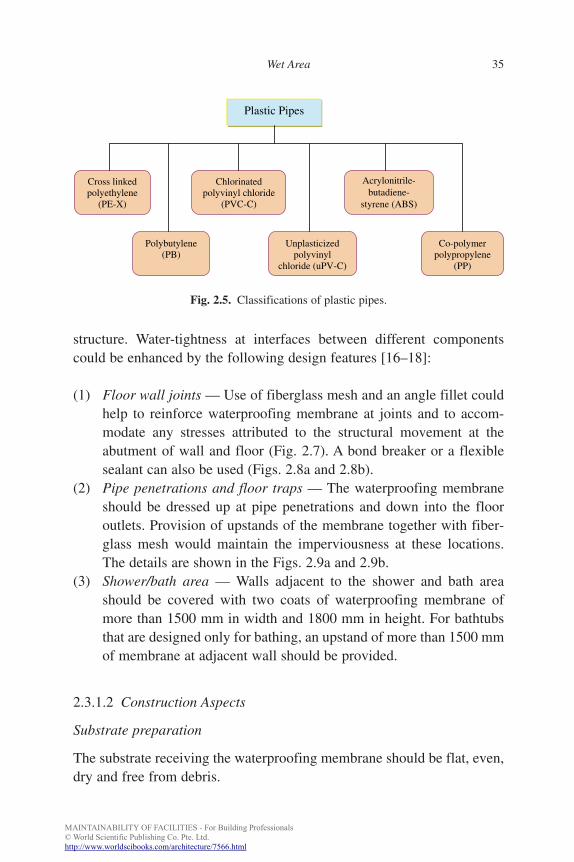
categories of plastics pipes used in wet areas (Fig. 2.5) [14, 15]. Majorreasons for the growth in use for plastic pipes are longer durability andcost saving in installation, labor and equipment due its lightweight.
2.3. Common Defects in Wet Areas
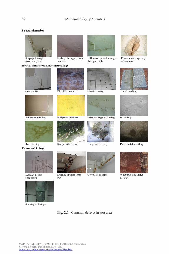
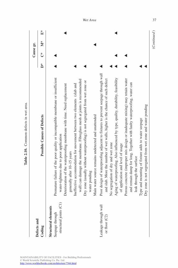
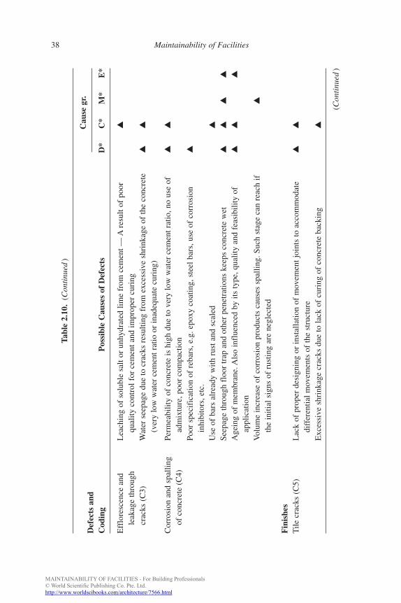
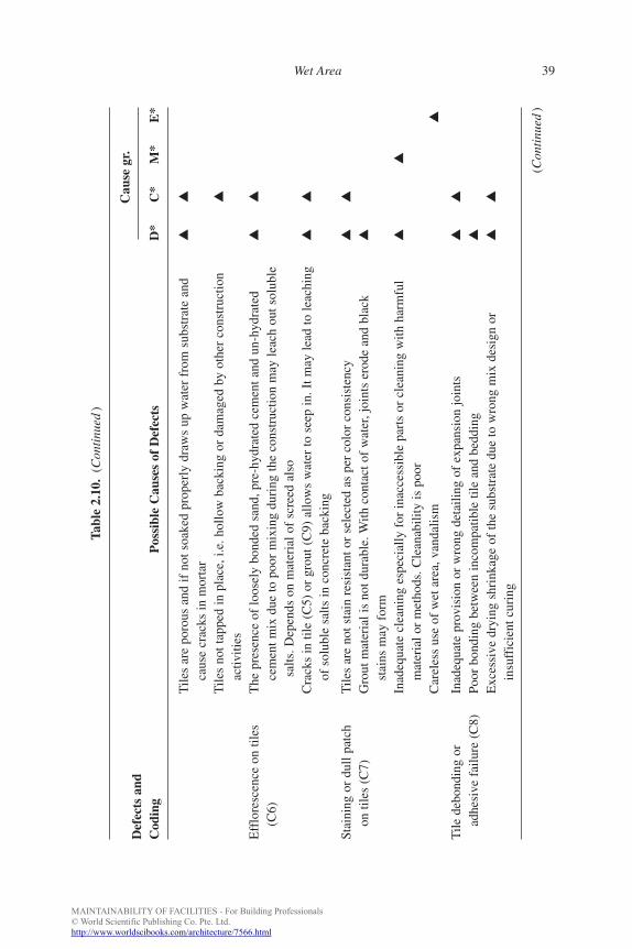
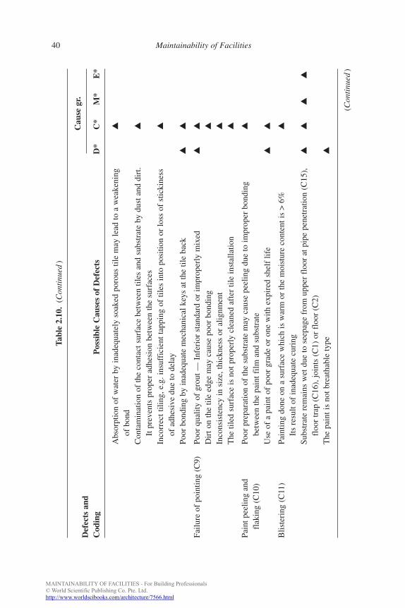
Common defects often found in wet areas, their possible cause and therole of the parties involved are shown in Fig. 2.6 and Table 2.10.
2.3.1. Waterproofing
2.3.1.1. Design Aspects
Water-tightness of wet areas relies mainly on the adequacy of water-proofing over penetrations, projections and joints and how thesediscontinuities of the floor and wall elements can achieve a “monolithic”
FA
34 Maintainability of Facilities
Table 2.9. Components of paint system.
Component Functions Comments
Primer • To reduce porosity of receiving The primers should be used tosurface so as to prevent undue reduce the porosity of the surfaceabsorption of resin from and have adequate moisturesubsequent coats of paints resistant capability
Sealer • To resist alkali attack from Sealers should be used to reduce thecement-based material porosity of the surface and have
• To stabilize loose surface adequate moisture resistantparticles capability
• To reduce porosity of receivingsurface so as to prevent undueabsorption of resin fromsubsequent coats of paints
Undercoat • To level out minor irregularities Choice of undercoat should beand provide uniform texture compatible with the primer/sealer
• To improve inter-coating and the finishing coatsadhesion
Topcoat • To provide the required The finishing coat of a paint systemfunctions of paint
b885_Chapter-02.qxd 12/29/2009 2:34 PM Page 34
MAINTAINABILITY OF FACILITIES - For Building Professionals© World Scientific Publishing Co. Pte. Ltd.http://www.worldscibooks.com/architecture/7566.html
structure. Water-tightness at interfaces between different componentscould be enhanced by the following design features [16–18]:
(1) Floor wall joints — Use of fiberglass mesh and an angle fillet couldhelp to reinforce waterproofing membrane at joints and to accom-modate any stresses attributed to the structural movement at theabutment of wall and floor (Fig. 2.7). A bond breaker or a flexiblesealant can also be used (Figs. 2.8a and 2.8b).
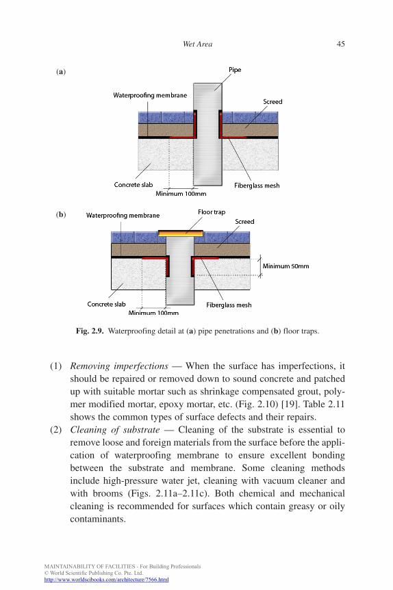
(2) Pipe penetrations and floor traps — The waterproofing membraneshould be dressed up at pipe penetrations and down into the flooroutlets. Provision of upstands of the membrane together with fiber-glass mesh would maintain the imperviousness at these locations.The details are shown in the Figs. 2.9a and 2.9b.
(3) Shower/bath area — Walls adjacent to the shower and bath areashould be covered with two coats of waterproofing membrane ofmore than 1500 mm in width and 1800 mm in height. For bathtubsthat are designed only for bathing, an upstand of more than 1500 mmof membrane at adjacent wall should be provided.
2.3.1.2 Construction Aspects
Substrate preparation
The substrate receiving the waterproofing membrane should be flat, even,dry and free from debris.
FA
Wet Area 35
Plastic Pipes
Cross linked polyethylene
(PE-X)
Polybutylene (PB)
Chlorinated polyvinyl chloride
(PVC-C)
Unplasticizedpolyvinyl
chloride (uPV-C)
Acrylonitrile-butadiene-
styrene (ABS)
Co-polymerpolypropylene
(PP)
Fig. 2.5. Classifications of plastic pipes.
b885_Chapter-02.qxd 12/29/2009 2:34 PM Page 35
MAINTAINABILITY OF FACILITIES - For Building Professionals© World Scientific Publishing Co. Pte. Ltd.http://www.worldscibooks.com/architecture/7566.html
FA
36 Maintainability of Facilities
Structural member
Seepage throughstructural joint
Leakage through porous concrete
Efflorescence and leakagethrough cracks
Corrosion and spallingof concrete
Internal finishes (wall, floor and ceiling)
Crack in tiles Tile efflorescence Grout staining Tile debonding
Failure of pointing Dull patch on stone Paint peeling and flaking Blistering
Rust staining Bio-growth: Algae Bio-growth: Fungi Patch on false ceiling
Fixture and fittings
Leakage at pipepenetration
Leakage through floor trap
Corrosion of pipe Water ponding underbathtub
Staining of fittings
Fig. 2.6. Common defects in wet area.
b885_Chapter-02.qxd 12/29/2009 2:35 PM Page 36
MAINTAINABILITY OF FACILITIES - For Building Professionals© World Scientific Publishing Co. Pte. Ltd.http://www.worldscibooks.com/architecture/7566.html
FA
Wet Area 37
Tabl
e 2.
10.
Com
mon
def
ects
in w
et a
rea.
Def
ects
and
Cau
se g
r.
Cod
ing
Pos
sibl
e C
ause
s of
Def
ects
D*
C*
M*
E*
Stru
ctur
al e
lem
ents
Seep
age
thro
ugh
Prem
atur
e fa
ilure
of
the
poor
qua
lity
or in
com
patib
le m
embr
ane
or in
suff
icie
nt▲
▲
stru
ctur
al jo
ints
(C
1)w
ater
-tig
htne
ss d
ue to
poo
r ap
plic
atio
nD
eter
iora
tion
of th
e w
ater
proo
fing
mem
bran
e w
ith ti
me.
Nee
d re
plac
emen
t▲
gene
rally
aft
er 1
0–15
yea
rsIn
effe
ctiv
e ac
com
mod
atio
n fo
r m
ovem
ent b
etw
een
two
elem
ents
(sl
ab a
nd▲
wal
l) c
an d
amag
e th
e m
embr
ane.
Fib
regl
ass
mes
h at
join
ts is
rec
omm
ende
dD
ry z
one
(usu
ally
with
out w
ater
proo
fing
) is
not
seg
rega
ted
from
wet
zon
e or
▲
wat
er p
ondi
ngM
ain
wat
er s
ourc
e re
mai
ns u
ndet
ecte
d an
d un
atte
nded
▲
Lea
kage
thro
ugh
wal
lPo
or d
esig
n of
wat
erpr
oofi
ng a
djac
ent t
o fi
xtur
es to
pre
vent
see
page
thro
ugh
wal
l▲
or f
loor
(C
2)an
d sl
ab. M
ore
the
num
ber
of w
et w
alls
, hig
her
is th
e ch
ance
of
such
def
ect
No
segr
egat
ion
of d
ry a
nd w
et z
one
▲
Agi
ng o
f w
ater
proo
fing
. Als
o in
flue
nced
by
type
, qua
lity,
dur
abili
ty, f
easi
bilit
y▲
▲▲
of a
pplic
atio
n an
d le
vel o
f us
age
Poro
us c
oncr
ete
(im
prop
er m
ix d
esig
n or
inad
equa
te m
ixin
g) m
ay r
etai
n w
ater
▲▲
and
rem
ain
dam
p fo
r lo
ng. T
oget
her
with
fau
lty w
ater
proo
fing
, wat
er c
anle
ak th
roug
h th
e su
rfac
eTy
pe a
nd m
ount
ing
of f
ixtu
re a
dds
to w
ater
see
page
▲
Dry
zon
e is
not
seg
rega
ted
from
wet
zon
e an
d w
ater
pon
ding
▲
(Con
tinu
ed)
b885_Chapter-02.qxd 12/29/2009 2:35 PM Page 37
MAINTAINABILITY OF FACILITIES - For Building Professionals© World Scientific Publishing Co. Pte. Ltd.http://www.worldscibooks.com/architecture/7566.html
FA
38 Maintainability of Facilities
Tabl
e 2.
10.
(Con
tinu
ed)
Def
ects
and
Cau
se g
r.
Cod
ing
Pos
sibl
e C
ause
s of
Def
ects
D*
C*
M*
E*
Eff
lore
scen
ce a
nd
Lea
chin
g of
sol
uble
sal
t or
unhy
drat
ed li
me
from
cem
ent —
Are
sult
of p
oor
▲
leak
age
thro
ugh
qual
ity c
ontr
ol f
or c
emen
t and
impr
oper
cur
ing
crac
ks (
C3)
Wat
er s
eepa
ge d
ue to
cra
cks
resu
lting
fro
m e
xces
sive
shr
inka
ge o
f th
e co
ncre
te▲
▲
(ver
y lo
w w
ater
cem
ent r
atio
or
inad
equa
te c
urin
g)
Cor
rosi
on a
nd s
palli
ngPe
rmea
bilit
y of
con
cret
e is
hig
h du
e to
ver
y lo
w w
ater
cem
ent r
atio
, no
use
of▲
▲
of c
oncr
ete
(C4)
adm
ixtu
re, p
oor
com
pact
ion
Poor
spe
cifi
catio
n of
reb
ars,
e.g
. epo
xy c
oatin
g, s
teel
bar
s, u
se o
f co
rros
ion
▲
inhi
bito
rs, e
tc.
Use
of
bars
alr
eady
with
rus
t and
sca
led
▲
Seep
age
thro
ugh
floo
r tr
ap a
nd o
ther
pen
etra
tions
kee
ps c
oncr
ete
wet
▲▲
▲▲
Age
ing
of m
embr
ane.
Als
o in
flue
nced
by
its ty
pe, q
ualit
y an
d fe
asib
ility
of
▲▲
▲
appl
icat
ion
Vol
ume
incr
ease
of
corr
osio
n pr
oduc
ts c
ause
s sp
allin
g. S
uch
stag
e ca
n re
ach
if
▲
the
initi
al s
igns
of
rust
ing
are
negl
ecte
d
Fin
ishe
sT
ile c
rack
s (C
5)L
ack
of p
rope
r de
sign
ing
or in
stal
latio
n of
mov
emen
t joi
nts
to a
ccom
mod
ate
▲▲
diff
eren
tial m
ovem
ents
of
the
stru
ctur
eE
xces
sive
shr
inka
ge c
rack
s du
e to
lack
of
curi
ng o
f co
ncre
te b
acki
ng▲
(Con
tinu
ed)
b885_Chapter-02.qxd 12/29/2009 2:35 PM Page 38
MAINTAINABILITY OF FACILITIES - For Building Professionals© World Scientific Publishing Co. Pte. Ltd.http://www.worldscibooks.com/architecture/7566.html
FA
Wet Area 39
Tabl
e 2.
10.
(Con
tinu
ed)
Def
ects
and
Cau
se g
r.
Cod
ing
Pos
sibl
e C
ause
s of
Def
ects
D*
C*
M*
E*
Tile
s ar
e po
rous
and
if n
ot s
oake
d pr
oper
ly d
raw
s up
wat
er f
rom
sub
stra
te a
nd▲
▲
caus
e cr
acks
in m
orta
rT
iles
not t
appe
d in
pla
ce, i
.e. h
ollo
w b
acki
ng o
r da
mag
ed b
y ot
her
cons
truc
tion
▲
activ
ities
Eff
lore
scen
ce o
n til
esT
he p
rese
nce
of lo
osel
y bo
nded
san
d, p
re-h
ydra
ted
cem
ent a
nd u
n-hy
drat
ed▲
▲
(C6)
cem
ent m
ix d
ue to
poo
r m
ixin
g du
ring
the
cons
truc
tion
may
leac
h ou
t sol
uble
salts
. Dep
ends
on
mat
eria
l of
scre
ed a
lso
Cra
cks
in ti
le (
C5)
or
grou
t (C
9) a
llow
s w
ater
to s
eep
in. I
t may
lead
to le
achi
ng▲
▲
of s
olub
le s
alts
in c
oncr
ete
back
ing
Stai
ning
or
dull
patc
hT
iles
are
not s
tain
res
ista
nt o
r se
lect
ed a
s pe
r co
lor
cons
iste
ncy
▲▲
on ti
les
(C7)
Gro
ut m
ater
ial i
s no
t dur
able
. With
con
tact
of
wat
er, j
oint
s er
ode
and
blac
k▲
stai
ns m
ay f
orm
Inad
equa
te c
lean
ing
espe
cial
ly f
or in
acce
ssib
le p
arts
or
clea
ning
with
har
mfu
l▲
▲
mat
eria
l or
met
hods
. Cle
anab
ility
is p
oor
Car
eles
s us
e of
wet
are
a, v
anda
lism
▲
Tile
deb
ondi
ng o
r In
adeq
uate
pro
visi
on o
r w
rong
det
ailin
g of
exp
ansi
on jo
ints
▲▲
adhe
sive
fai
lure
(C
8)Po
or b
ondi
ng b
etw
een
inco
mpa
tible
tile
and
bed
ding
▲
Exc
essi
ve d
ryin
g sh
rink
age
of th
e su
bstr
ate
due
to w
rong
mix
des
ign
or
▲▲
insu
ffic
ient
cur
ing
(Con
tinu
ed)
b885_Chapter-02.qxd 12/29/2009 2:35 PM Page 39
MAINTAINABILITY OF FACILITIES - For Building Professionals© World Scientific Publishing Co. Pte. Ltd.http://www.worldscibooks.com/architecture/7566.html
Tabl
e 2.
10.
(Con
tinu
ed)
Def
ects
and
Cau
se g
r.
Cod
ing
Pos
sibl
e C
ause
s of
Def
ects
D*
C*
M*
E*
Abs
orpt
ion
of w
ater
by
inad
equa
tely
soa
ked
poro
us ti
le m
ay le
ad to
a w
eake
ning
▲
of b
ond
Con
tam
inat
ion
of th
e co
ntac
t sur
face
bet
wee
n til
es a
nd s
ubst
rate
by
dust
and
dir
t.▲
It p
reve
nts
prop
er a
dhes
ion
betw
een
the
surf
aces
Inco
rrec
t tili
ng, e
.g. i
nsuf
fici
ent t
appi
ng o
f til
es in
to p
ositi
on o
r lo
ss o
f st
icki
ness
▲
of a
dhes
ive
due
to d
elay
Poor
bon
ding
by
inad
equa
te m
echa
nica
l key
s at
the
tile
back
▲▲
Failu
re o
f po
intin
g (C
9)Po
or q
ualit
y of
gro
ut —
Inf
erio
r st
anda
rd o
r im
prop
erly
mix
ed▲
▲
Dir
t on
the
tile
edge
may
cau
se p
oor
bond
ing
▲
Inco
nsis
tenc
y in
siz
e, th
ickn
ess
or a
lignm
ent
▲
The
tile
d su
rfac
e is
not
pro
perl
y cl
eane
d af
ter
tile
inst
alla
tion
▲
Pain
t pee
ling
and
Poor
pre
para
tion
of th
e su
bstr
ate
may
cau
se p
eelin
g du
e to
impr
oper
bon
ding
▲
flak
ing
(C10
)be
twee
n th
e pa
int f
ilm a
nd s
ubst
rate
Use
of
a pa
int o
f po
or g
rade
or
one
with
exp
ired
she
lf li
fe▲
▲
Blis
teri
ng (
C11
)Pa
intin
g do
ne o
n a
surf
ace
whi
ch is
war
m o
r th
e m
oist
ure
cont
ent i
s >
6%
▲
Its
resu
lt of
inad
equa
te c
urin
gSu
bstr
ate
rem
ains
wet
due
to s
eepa
ge f
rom
upp
er f
loor
at p
ipe
pene
trat
ion
(C15
),▲
▲▲
▲
floo
r tr
ap (
C16
), jo
ints
(C
1) o
r fl
oor
(C2)
The
pai
nt is
not
bre
atha
ble
type
▲
(Con
tinu
ed)
FA
40 Maintainability of Facilities
b885_Chapter-02.qxd 12/29/2009 2:35 PM Page 40
MAINTAINABILITY OF FACILITIES - For Building Professionals© World Scientific Publishing Co. Pte. Ltd.http://www.worldscibooks.com/architecture/7566.html
FA
Wet Area 41
Tabl
e 2.
10.
(Con
tinu
ed)
Def
ects
and
Cau
se g
r.
Cod
ing
Pos
sibl
e C
ause
s of
Def
ects
D*
C*
M*
E*
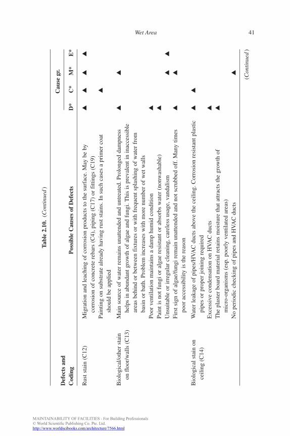
Rus
t sta
in (
C12
)M
igra
tion
and
leac
hing
of
corr
osio
n pr
oduc
ts to
the
surf
ace.
May
be
by
▲▲
▲▲
corr
osio
n of
con
cret
e re
bars
(C
4), p
ipin
g (C
17)
or f
ittin
gs (
C19
)Pa
intin
g on
sub
stra
te a
lrea
dy h
avin
g ru
st s
tain
s. I
n su
ch c
ases
a p
rim
er c
oat
▲
shou
ld b
e ap
plie
d
Bio
logi
cal/o
ther
sta
inM
ain
sour
ce o
f w
ater
rem
ains
una
ttend
ed a
nd u
ntre
ated
. Pro
long
ed d
ampn
ess
▲▲
on f
loor
/wal
ls (
C13
)he
lps
in a
bund
ant g
row
th o
f al
gae
and
fung
i. T
his
is p
reva
lent
in in
acce
ssib
lear
eas
behi
nd o
r be
twee
n fi
xtur
es o
r w
ith f
requ
ent s
plas
hing
of
wat
er f
rom
basi
n or
bat
h. P
robl
em in
crea
ses
with
mor
e nu
mbe
r of
wet
wal
lsPo
or v
entil
atio
n m
aint
ains
a d
amp
hum
id c
ondi
tion
▲
Pain
t is
not f
ungi
or
alga
e re
sist
ant o
r ab
sorb
s w
ater
(no
nwas
habl
e)▲
Uns
uita
ble
or ir
regu
lar
clea
ning
, car
eles
s us
age,
van
dalis
m▲
▲
Firs
t sig
n of
alg
ae/f
ungi
rem
ain
unat
tend
ed a
nd n
ot s
crub
bed
off.
Man
y tim
es▲
▲
poor
acc
essi
bilit
y is
the
reas
on
Bio
logi
cal s
tain
on
Wat
er le
akag
e of
pip
es/H
VA
C d
ucts
abo
ve th
e ce
iling
. Cor
rosi
on r
esis
tant
pla
stic
▲▲
ceili
ng (
C14
)pi
pes
or p
rope
r jo
inin
g re
quir
edE
xces
sive
con
dens
atio
n on
HV
AC
duc
ts▲
The
pla
ster
boa
rd m
ater
ial r
etai
ns m
oist
ure
that
attr
acts
the
grow
th o
f▲
mic
ro-o
rgan
ism
s (e
sp. p
oorl
y ve
ntila
ted
area
s)N
o pe
riod
ic c
heck
ing
of p
ipes
and
HV
AC
duc
ts▲
(Con
tinu
ed)
b885_Chapter-02.qxd 12/29/2009 2:35 PM Page 41
MAINTAINABILITY OF FACILITIES - For Building Professionals© World Scientific Publishing Co. Pte. Ltd.http://www.worldscibooks.com/architecture/7566.html
FA
42 Maintainability of Facilities
Tabl
e 2.
10.
(Con
tinu
ed)
Def
ects
and
Cau
se g
r.
Cod
ing
Pos
sibl
e C
ause
s of
Def
ects
D*
C*
M*
E*
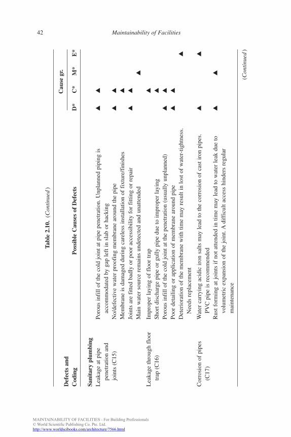
Sani
tary
plu
mbi
ngL
eaka
ge a
t pip
ePo
rous
infi
ll of
the
cold
join
t at p
ipe
pene
trat
ion.
Unp
lann
ed p
ipin
g is
▲▲
pene
trat
ion
and
acco
mm
odat
ed b
y ga
p le
ft in
sla
b or
hac
king
join
ts (
C15
)N
o/de
fect
ive
wat
er p
roof
ing
mem
bran
e ar
ound
the
pipe
▲▲
Mem
bran
e is
dam
aged
dur
ing
care
less
inst
alla
tion
of f
ixtu
re/f
inis
hes
▲
Join
ts a
re f
itted
bad
ly o
r po
or a
cces
sibi
lity
for
fitti
ng o
r re
pair
▲▲
Mai
n w
ater
sou
rce
rem
ains
und
etec
ted
and
unat
tend
ed▲
Lea
kage
thro
ugh
floo
rIm
prop
er la
ying
of
floo
r tr
ap▲
trap
(C
16)
Shor
t dis
char
ge p
ipe
or g
ully
pip
e du
e to
impr
oper
layi
ng▲
Poro
us in
fill
of th
e co
ld jo
int a
t the
pen
etra
tion
(usu
ally
unp
lann
ed)
▲▲
Poor
det
ailin
g or
app
licat
ion
of m
embr
ane
arou
nd p
ipe
▲▲
Det
erio
ratio
n of
the
mem
bran
e w
ith ti
me
may
res
ult i
n lo
st o
f w
ater
-tig
htne
ss.
▲
Nee
ds r
epla
cem
ent
Cor
rosi
on o
f pi
pes
Wat
er c
arry
ing
acid
ic ir
on s
alts
may
lead
to th
e co
rros
ion
of c
ast i
ron
pipe
s.
▲▲
(C17
)PV
C p
ipe
is r
ecom
men
ded
Rus
t for
min
g at
join
ts if
not
atte
nded
in ti
me
may
lead
to w
ater
leak
due
to
▲▲
volu
met
ric
expa
nsio
n of
the
join
t. A
diff
icul
t acc
ess
hind
ers
regu
lar
mai
nten
ance
(Con
tinu
ed)
b885_Chapter-02.qxd 12/29/2009 2:35 PM Page 42
MAINTAINABILITY OF FACILITIES - For Building Professionals© World Scientific Publishing Co. Pte. Ltd.http://www.worldscibooks.com/architecture/7566.html
Tabl
e 2.
10.
(Con
tinu
ed)
Def
ects
and
Cau
se g
r.
Cod
ing
Pos
sibl
e C
ause
s of
Def
ects
D*
C*
M*
E*
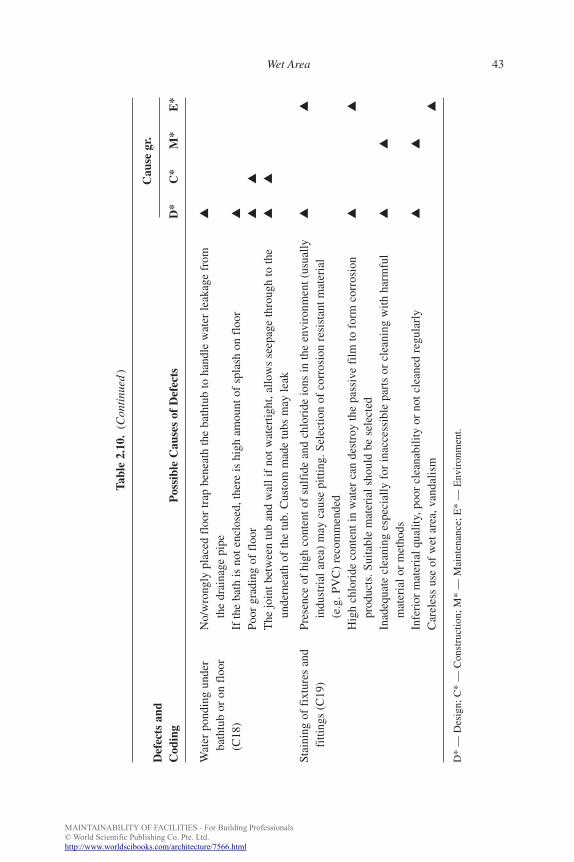
Wat
er p
ondi
ng u
nder
No/
wro
ngly
pla
ced
floo
r tr
ap b
enea
th th
e ba
thtu
b to
han
dle
wat
er le
akag
e fr
om▲
bath
tub
or o
n fl
oor
the
drai
nage
pip
e(C
18)
If th
e ba
th is
not
enc
lose
d, th
ere
is h
igh
amou
nt o
f sp
lash
on
floo
r▲
Poor
gra
ding
of
floo
r▲
▲
The
join
t bet
wee
n tu
b an
d w
all i
f no
t wat
ertig
ht, a
llow
s se
epag
e th
roug
h to
the
▲▲
unde
rnea
th o
f th
e tu
b. C
usto
m m
ade
tubs
may
leak
Stai
ning
of
fixt
ures
and
Pres
ence
of
high
con
tent
of
sulf
ide
and
chlo
ride
ions
in th
e en
viro
nmen
t (us
ually
▲▲
fitti
ngs
(C19
)in
dust
rial
are
a) m
ay c
ause
pitt
ing.
Sel
ectio
n of
cor
rosi
on r
esis
tant
mat
eria
l(e
.g. P
VC
) re
com
men
ded
Hig
h ch
lori
de c
onte
nt in
wat
er c
an d
estr
oy th
e pa
ssiv
e fi
lm to
for
m c
orro
sion
▲▲
prod
ucts
. Sui
tabl
e m
ater
ial s
houl
d be
sel
ecte
dIn
adeq
uate
cle
anin
g es
peci
ally
for
inac
cess
ible
par
ts o
r cl
eani
ng w
ith h
arm
ful
▲▲
mat
eria
l or
met
hods
Infe
rior
mat
eria
l qua
lity,
poo
r cl
eana
bilit
y or
not
cle
aned
reg
ular
ly▲
▲
Car
eles
s us
e of
wet
are
a, v
anda
lism
▲
D*
— D
esig
n; C
* —
Con
stru
ctio
n; M
* —
Mai
nten
ance
; E*
— E
nvir
onm
ent.
FA
Wet Area 43
b885_Chapter-02.qxd 12/29/2009 2:35 PM Page 43
MAINTAINABILITY OF FACILITIES - For Building Professionals© World Scientific Publishing Co. Pte. Ltd.http://www.worldscibooks.com/architecture/7566.html
FA
44 Maintainability of Facilities
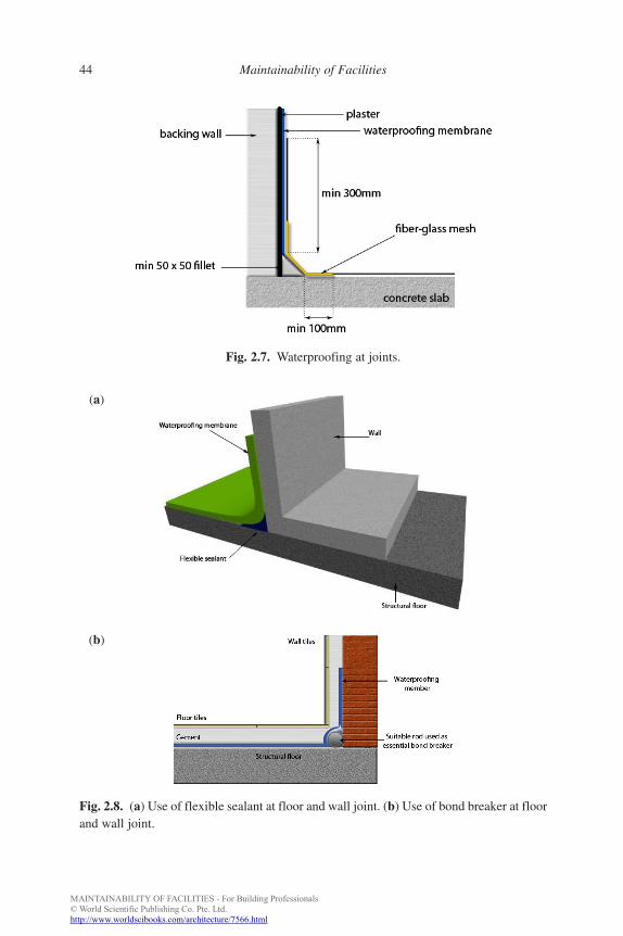
Fig. 2.7. Waterproofing at joints.
Fig. 2.8. (a) Use of flexible sealant at floor and wall joint. (b) Use of bond breaker at floorand wall joint.
(a)
(b)
b885_Chapter-02.qxd 12/29/2009 2:35 PM Page 44
MAINTAINABILITY OF FACILITIES - For Building Professionals© World Scientific Publishing Co. Pte. Ltd.http://www.worldscibooks.com/architecture/7566.html
FA
Wet Area 45
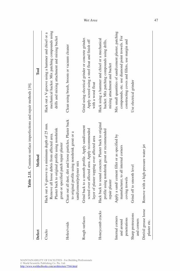
(1) Removing imperfections — When the surface has imperfections, itshould be repaired or removed down to sound concrete and patchedup with suitable mortar such as shrinkage compensated grout, poly-mer modified mortar, epoxy mortar, etc. (Fig. 2.10) [19]. Table 2.11shows the common types of surface defects and their repairs.
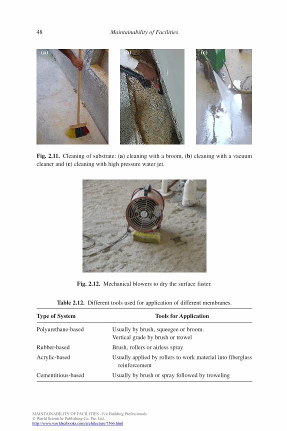
(2) Cleaning of substrate — Cleaning of the substrate is essential toremove loose and foreign materials from the surface before the appli-cation of waterproofing membrane to ensure excellent bondingbetween the substrate and membrane. Some cleaning methodsinclude high-pressure water jet, cleaning with vacuum cleaner andwith brooms (Figs. 2.11a–2.11c). Both chemical and mechanicalcleaning is recommended for surfaces which contain greasy or oilycontaminants.
Fig. 2.9. Waterproofing detail at (a) pipe penetrations and (b) floor traps.
(a)
(b)
b885_Chapter-02.qxd 12/29/2009 2:35 PM Page 45

MAINTAINABILITY OF FACILITIES - For Building Professionals© World Scientific Publishing Co. Pte. Ltd.http://www.worldscibooks.com/architecture/7566.html
FA
46 Maintainability of Facilities
Fig. 2.10. (a) Removing a defective concrete. (b) Patching with mortar.
(a) (b)
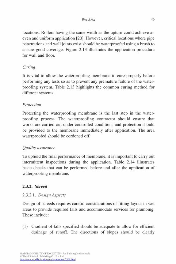
(3) Removing surface dampness — Excess water should be removedfrom the surface prior to waterproofing application. Surface can bedried by natural ventilation or with the use of mechanical blowers toaccelerate the drying process (Fig. 2.12).
Membrane application
Considerations should include:
(1) Size of the team — In internal wet areas, the area to be waterproofedis relatively small thus the size of the team should not be too largegiven the space constraints.
(2) Size of the mixes — Mixing of waterproofing products should bedone in a controlled environment according to the manufacturer’sspecifications. All waterproofing products should be mixed mechan-ically to ensure even mixing. The proportion of a two-part system ifnot pre-packed, should be measured out as accurately as possible andmixed within the specified time.
(3) Tools — Tools and equipment used for application should be cleanedbefore and immediately after application. Table 2.12 shows thedifferent tools used for different types of systems.
The application of membrane should begin at a corner: diagonal to theentrance and upturns at wall floor junctions, to avoid stepping on appliedarea. Rollers or brushes can be used for application of membrane in most
b885_Chapter-02.qxd 12/29/2009 2:35 PM Page 46
MAINTAINABILITY OF FACILITIES - For Building Professionals© World Scientific Publishing Co. Pte. Ltd.http://www.worldscibooks.com/architecture/7566.html
FA
Wet Area 47
Tabl
e 2.
11.
Com
mon
sur
face
impe
rfec
tions
and
rep
air
met
hods
[16
].
Def
ect
Met
hod
Tool
Cra
cks
Hac
k ou
t a V
-gro
ove
to a
min
imum
dep
th o
f 25
mm
.H
ack
out a
V-g
roov
e us
ing
a ha
mm
er a
nd c
hise
l or
aR
emov
e al
l loo
se d
ebri
s fr
om a
ffec
ted
area
.m
echa
nica
l hac
ker.
Mix
pat
chin
g co
mpo
unds
usi
ngPl
aste
r ba
ck to
ori
gina
l pro
file
usi
ng n
onsh
rink
drill
s an
d m
ixin
g at
tach
men
t and
mix
ing
buck
etgr
out o
r sp
ecif
ied
patc
h re
pair
pla
ster
Hol
es/v
oids
Cle
an o
ut a
ll du
st, d
irt a
nd lo
ose
part
icle
s. P
last
er b
ack
Cle
an u
sing
bru
sh, b
room
or
vacu
um c
lean
erto
ori
gina
l pro
file
usi
ng n
onsh
rink
gro
ut o
r a
sand
/cem
ent/p
olym
er m
ix
Rou
gh s
urfa
ces
Gri
nd b
ack
to a
sm
ooth
pro
file
. App
ly s
and/
cem
ent
Gri
nd u
sing
ele
ctri
cal g
rind
er o
r co
ncre
te g
rind
er.
scre
ed o
ver
affe
cted
are
a. A
pply
rec
omm
ende
dA
pply
scr
eed
usin
g a
stee
l flo
at a
nd f
inis
h of
fla
yer
of p
last
er to
ppin
g ov
er a
ffec
ted
area
with
a w
ood
floa
t
Hon
eyco
mb
crac
ksH
ack
back
to s
ound
con
cret
e. P
last
er b
ack
to o
rigi
nal
Hac
k us
ing
a ha
mm
er a
nd c
hise
l or
a m
echa
nica
lpr
ofile
usi
ng n
onsh
rink
gro
ut o
r re
com
men
ded
hack
er. M
ix p
atch
ing
com
poun
ds u
sing
dri
lls,
repa
ir p
last
erm
ixin
g at
tach
men
t and
buc
ket
Inte
rnal
cor
ners
App
ly a
san
d/ c
emen
t fill
et o
r as
spe
cifi
ed b
yM
ix s
mal
l qua
ntiti
es o
f sa
nd/c
emen
t pla
ster
, pat
chin
gan
d ar
ound
man
ufac
ture
r, to
all
inte
rnal
cor
ners
com
poun
ds, e
tc. u
se d
iam
ond
poin
t tro
wel
s. F
orpe
netr
atio
nsco
ving
trow
els
cons
truc
ting
cove
s an
d fi
llets
, use
mar
gin
and
Shar
p pr
otru
sion
sG
rind
off
to s
moo
th le
vel
Use
ele
ctri
cal g
rind
eran
d co
rner
s
Dir
t/oil
grea
se lo
ose
Rem
ove
with
a h
igh-
pres
sure
wat
er je
tpl
aste
r et
c.
b885_Chapter-02.qxd 12/29/2009 2:35 PM Page 47
MAINTAINABILITY OF FACILITIES - For Building Professionals© World Scientific Publishing Co. Pte. Ltd.http://www.worldscibooks.com/architecture/7566.html
FA
48 Maintainability of Facilities
Fig. 2.11. Cleaning of substrate: (a) cleaning with a broom, (b) cleaning with a vacuumcleaner and (c) cleaning with high pressure water jet.
(a) (b) (c)
Table 2.12. Different tools used for application of different membranes.
Type of System Tools for Application
Polyurethane-based Usually by brush, squeegee or broom.Vertical grade by brush or trowel
Rubber-based Brush, rollers or airless spray
Acrylic-based Usually applied by rollers to work material into fiberglassreinforcement
Cementitious-based Usually by brush or spray followed by troweling
Fig. 2.12. Mechanical blowers to dry the surface faster.
b885_Chapter-02.qxd 12/29/2009 2:35 PM Page 48
MAINTAINABILITY OF FACILITIES - For Building Professionals© World Scientific Publishing Co. Pte. Ltd.http://www.worldscibooks.com/architecture/7566.html
FA
Wet Area 49
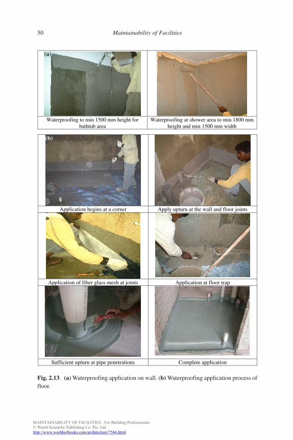
locations. Rollers having the same width as the upturn could achieve aneven and uniform application [20]. However, critical locations where pipepenetrations and wall joints exist should be waterproofed using a brush toensure good coverage. Figure 2.13 illustrates the application procedurefor wall and floor.
Curing
It is vital to allow the waterproofing membrane to cure properly beforeperforming any tests so as to prevent any premature failure of the water-proofing system. Table 2.13 highlights the common curing method fordifferent systems.
Protection
Protecting the waterproofing membrane is the last step in the water-proofing process. The waterproofing contractor should ensure thatworks are carried out under controlled conditions and protection shouldbe provided to the membrane immediately after application. The areawaterproofed should be cordoned off.
Quality assurance
To uphold the final performance of membrane, it is important to carry outintermittent inspections during the application. Table 2.14 illustratesbasic checks that can be performed before and after the application ofwaterproofing membrane.
2.3.2. Screed
2.3.2.1. Design Aspects
Design of screeds requires careful considerations of fitting layout in wetareas to provide required falls and accommodate services for plumbing.These include:
(1) Gradient of falls specified should be adequate to allow for efficientdrainage of runoff. The directions of slopes should be clearly
b885_Chapter-02.qxd 12/29/2009 2:35 PM Page 49
MAINTAINABILITY OF FACILITIES - For Building Professionals© World Scientific Publishing Co. Pte. Ltd.http://www.worldscibooks.com/architecture/7566.html
FA
50 Maintainability of Facilities
Fig. 2.13. (a) Waterproofing application on wall. (b) Waterproofing application process offloor.
Waterproofing to min 1500 mm height forbathtub area
Waterproofing at shower area to min 1800 mmheight and min 1500 mm width
Application begins at a corner Apply upturn at the wall and floor joints
Application of fiber glass mesh at joints Application at floor trap
Sufficient upturn at pipe penetrations Complete application
(a)
(b)
b885_Chapter-02.qxd 12/29/2009 2:35 PM Page 50
MAINTAINABILITY OF FACILITIES - For Building Professionals© World Scientific Publishing Co. Pte. Ltd.http://www.worldscibooks.com/architecture/7566.html
FA
Wet Area 51
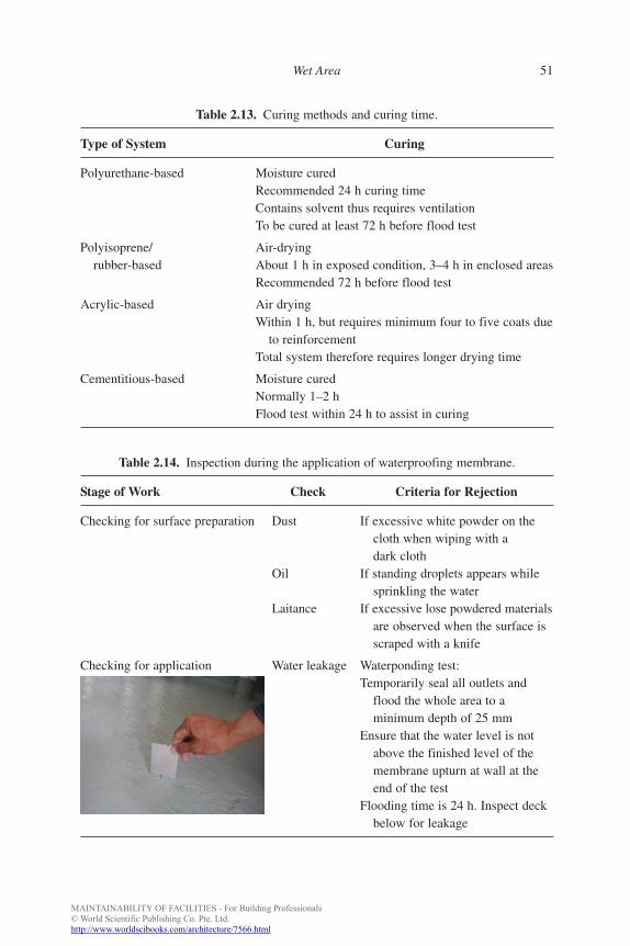
Table 2.13. Curing methods and curing time.
Type of System Curing
Polyurethane-based Moisture curedRecommended 24 h curing timeContains solvent thus requires ventilationTo be cured at least 72 h before flood test
Polyisoprene/ Air-dryingrubber-based About 1 h in exposed condition, 3–4 h in enclosed areas
Recommended 72 h before flood test
Acrylic-based Air dryingWithin 1 h, but requires minimum four to five coats due
to reinforcementTotal system therefore requires longer drying time
Cementitious-based Moisture curedNormally 1–2 hFlood test within 24 h to assist in curing
Table 2.14. Inspection during the application of waterproofing membrane.
Stage of Work Check Criteria for Rejection
Checking for surface preparation Dust If excessive white powder on thecloth when wiping with adark cloth
Oil If standing droplets appears whilesprinkling the water
Laitance If excessive lose powdered materialsare observed when the surface isscraped with a knife
Checking for application Water leakage Waterponding test:Temporarily seal all outlets and
flood the whole area to aminimum depth of 25 mm
Ensure that the water level is notabove the finished level of themembrane upturn at wall at theend of the test
Flooding time is 24 h. Inspect deckbelow for leakage
b885_Chapter-02.qxd 12/29/2009 2:35 PM Page 51
MAINTAINABILITY OF FACILITIES - For Building Professionals© World Scientific Publishing Co. Pte. Ltd.http://www.worldscibooks.com/architecture/7566.html
FA
52 Maintainability of Facilities
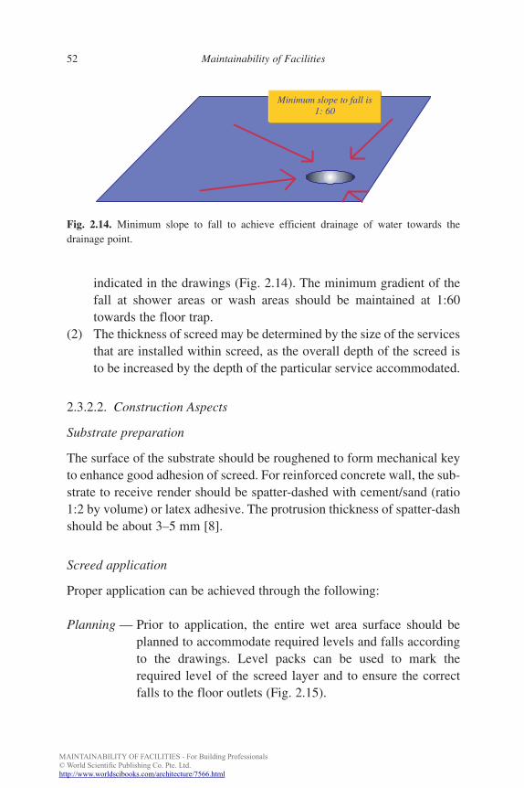
indicated in the drawings (Fig. 2.14). The minimum gradient of thefall at shower areas or wash areas should be maintained at 1:60towards the floor trap.
(2) The thickness of screed may be determined by the size of the servicesthat are installed within screed, as the overall depth of the screed isto be increased by the depth of the particular service accommodated.
2.3.2.2. Construction Aspects
Substrate preparation
The surface of the substrate should be roughened to form mechanical keyto enhance good adhesion of screed. For reinforced concrete wall, the sub-strate to receive render should be spatter-dashed with cement/sand (ratio1:2 by volume) or latex adhesive. The protrusion thickness of spatter-dashshould be about 3–5 mm [8].
Screed application
Proper application can be achieved through the following:
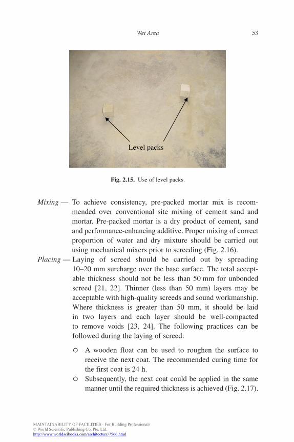
Planning — Prior to application, the entire wet area surface should beplanned to accommodate required levels and falls accordingto the drawings. Level packs can be used to mark therequired level of the screed layer and to ensure the correctfalls to the floor outlets (Fig. 2.15).
Fig. 2.14. Minimum slope to fall to achieve efficient drainage of water towards thedrainage point.
Minimum slope to fall is1: 60
b885_Chapter-02.qxd 12/29/2009 2:35 PM Page 52
MAINTAINABILITY OF FACILITIES - For Building Professionals© World Scientific Publishing Co. Pte. Ltd.http://www.worldscibooks.com/architecture/7566.html
FA
Wet Area 53
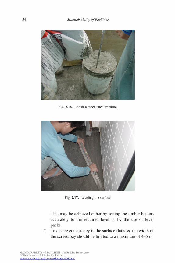
Mixing — To achieve consistency, pre-packed mortar mix is recom-mended over conventional site mixing of cement sand andmortar. Pre-packed mortar is a dry product of cement, sandand performance-enhancing additive. Proper mixing of correctproportion of water and dry mixture should be carried outusing mechanical mixers prior to screeding (Fig. 2.16).
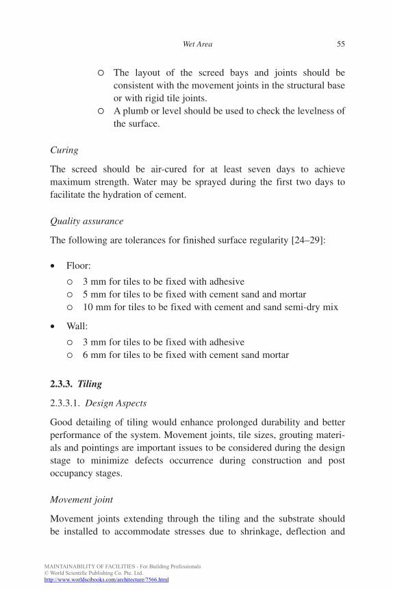
Placing — Laying of screed should be carried out by spreading10–20 mm surcharge over the base surface. The total accept-able thickness should not be less than 50 mm for unbondedscreed [21, 22]. Thinner (less than 50 mm) layers may beacceptable with high-quality screeds and sound workmanship.Where thickness is greater than 50 mm, it should be laidin two layers and each layer should be well-compactedto remove voids [23, 24]. The following practices can befollowed during the laying of screed:
� A wooden float can be used to roughen the surface toreceive the next coat. The recommended curing time forthe first coat is 24 h.
� Subsequently, the next coat could be applied in the samemanner until the required thickness is achieved (Fig. 2.17).
Level packs
Fig. 2.15. Use of level packs.
b885_Chapter-02.qxd 12/29/2009 2:35 PM Page 53
MAINTAINABILITY OF FACILITIES - For Building Professionals© World Scientific Publishing Co. Pte. Ltd.http://www.worldscibooks.com/architecture/7566.html
FA
54 Maintainability of Facilities
This may be achieved either by setting the timber battensaccurately to the required level or by the use of level packs.
� To ensure consistency in the surface flatness, the width ofthe screed bay should be limited to a maximum of 4–5 m.
Fig. 2.16. Use of a mechanical mixture.
Fig. 2.17. Leveling the surface.
b885_Chapter-02.qxd 12/29/2009 2:35 PM Page 54
MAINTAINABILITY OF FACILITIES - For Building Professionals© World Scientific Publishing Co. Pte. Ltd.http://www.worldscibooks.com/architecture/7566.html
FA
Wet Area 55
� The layout of the screed bays and joints should beconsistent with the movement joints in the structural baseor with rigid tile joints.
� A plumb or level should be used to check the levelness ofthe surface.
Curing
The screed should be air-cured for at least seven days to achievemaximum strength. Water may be sprayed during the first two days tofacilitate the hydration of cement.
Quality assurance
The following are tolerances for finished surface regularity [24–29]:
• Floor:
� 3 mm for tiles to be fixed with adhesive� 5 mm for tiles to be fixed with cement sand and mortar� 10 mm for tiles to be fixed with cement and sand semi-dry mix
• Wall:
� 3 mm for tiles to be fixed with adhesive� 6 mm for tiles to be fixed with cement sand mortar
2.3.3. Tiling
2.3.3.1. Design Aspects
Good detailing of tiling would enhance prolonged durability and betterperformance of the system. Movement joints, tile sizes, grouting materi-als and pointings are important issues to be considered during the designstage to minimize defects occurrence during construction and postoccupancy stages.
Movement joint
Movement joints extending through the tiling and the substrate shouldbe installed to accommodate stresses due to shrinkage, deflection and
b885_Chapter-02.qxd 12/29/2009 2:35 PM Page 55
MAINTAINABILITY OF FACILITIES - For Building Professionals© World Scientific Publishing Co. Pte. Ltd.http://www.worldscibooks.com/architecture/7566.html
FA
56 Maintainability of Facilities
moisture. The recommended maximum spacing and width of movementjoints [23] are:
• Internal wall: Horizontal and vertical directions: 5–6 m• Wall joint width: Minimum 3 mm, preferred 5 mm• Internal floor: 5–7 m in all directions• Floor joint width: Minimum 5 mm
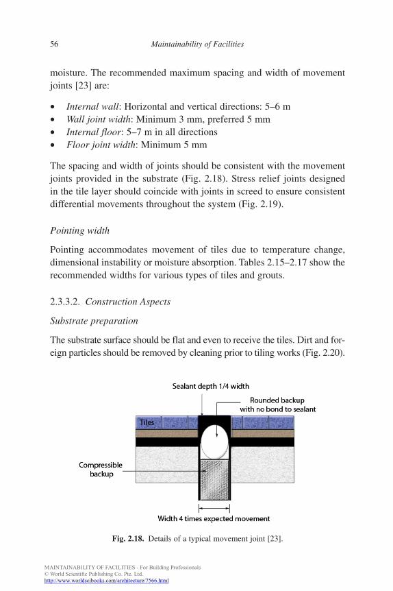
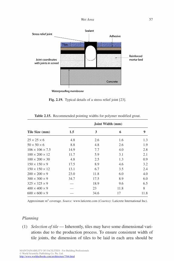
The spacing and width of joints should be consistent with the movementjoints provided in the substrate (Fig. 2.18). Stress relief joints designedin the tile layer should coincide with joints in screed to ensure consistentdifferential movements throughout the system (Fig. 2.19).
Pointing width
Pointing accommodates movement of tiles due to temperature change,dimensional instability or moisture absorption. Tables 2.15–2.17 show therecommended widths for various types of tiles and grouts.
2.3.3.2. Construction Aspects
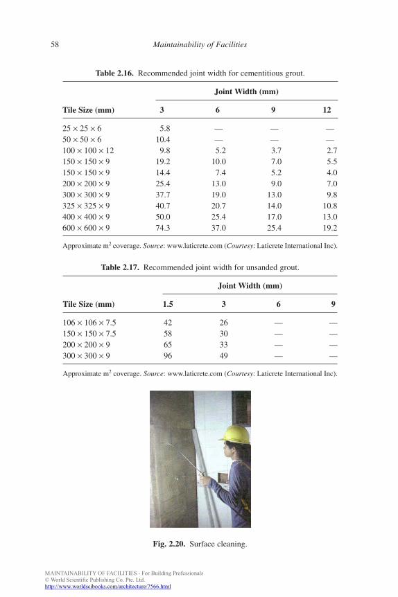
Substrate preparation
The substrate surface should be flat and even to receive the tiles. Dirt and for-eign particles should be removed by cleaning prior to tiling works (Fig. 2.20).
Fig. 2.18. Details of a typical movement joint [23].
b885_Chapter-02.qxd 12/29/2009 2:35 PM Page 56
MAINTAINABILITY OF FACILITIES - For Building Professionals© World Scientific Publishing Co. Pte. Ltd.http://www.worldscibooks.com/architecture/7566.html
FA
Wet Area 57
Planning
(1) Selection of tile — Inherently, tiles may have some dimensional vari-ations due to the production process. To ensure consistent width oftile joints, the dimension of tiles to be laid in each area should be
Table 2.15. Recommended pointing widths for polymer modified grout.
Joint Width (mm)
Tile Size (mm) 1.5 3 6 9
25 × 25 × 6 4.8 2.6 1.6 1.350 × 50 × 6 8.8 4.8 2.6 1.9106 × 106 × 7.5 14.9 7.7 4.0 2.8100 × 200 × 12 11.7 5.9 3.1 2.1100 × 200 × 30 4.8 2.5 1.3 0.9150 × 150 × 9 17.5 8.9 4.6 3.2150 × 150 × 12 13.1 6.7 3.5 2.4200 × 200 × 9 23.0 11.8 6.0 4.0300 × 300 × 9 34.7 17.5 8.9 6.0325 × 325 × 9 — 18.9 9.6 6.5400 × 400 × 9 — 23 11.8 8600 × 600 × 9 — 34.6 17 11.8
Approximate m2 coverage. Source: www.laticrete.com (Courtesy: Laticrete International Inc).
Fig. 2.19. Typical details of a stress relief joint [23].
b885_Chapter-02.qxd 12/29/2009 2:35 PM Page 57
MAINTAINABILITY OF FACILITIES - For Building Professionals© World Scientific Publishing Co. Pte. Ltd.http://www.worldscibooks.com/architecture/7566.html
FA
58 Maintainability of Facilities
Table 2.16. Recommended joint width for cementitious grout.
Joint Width (mm)
Tile Size (mm) 3 6 9 12
25 × 25 × 6 5.8 — — —50 × 50 × 6 10.4 — — —100 × 100 × 12 9.8 5.2 3.7 2.7150 × 150 × 9 19.2 10.0 7.0 5.5150 × 150 × 9 14.4 7.4 5.2 4.0200 × 200 × 9 25.4 13.0 9.0 7.0300 × 300 × 9 37.7 19.0 13.0 9.8325 × 325 × 9 40.7 20.7 14.0 10.8400 × 400 × 9 50.0 25.4 17.0 13.0600 × 600 × 9 74.3 37.0 25.4 19.2
Approximate m2 coverage. Source: www.laticrete.com (Courtesy: Laticrete International Inc).
Fig. 2.20. Surface cleaning.
Table 2.17. Recommended joint width for unsanded grout.
Joint Width (mm)
Tile Size (mm) 1.5 3 6 9
106 × 106 × 7.5 42 26 — —150 × 150 × 7.5 58 30 — —200 × 200 × 9 65 33 — —300 × 300 × 9 96 49 — —
Approximate m2 coverage. Source: www.laticrete.com (Courtesy: Laticrete International Inc).
b885_Chapter-02.qxd 12/29/2009 2:35 PM Page 58
MAINTAINABILITY OF FACILITIES - For Building Professionals© World Scientific Publishing Co. Pte. Ltd.http://www.worldscibooks.com/architecture/7566.html
FA
Wet Area 59
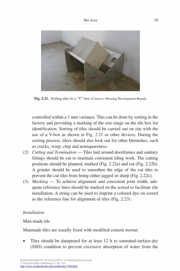
controlled within a 1 mm variance. This can be done by sorting in thefactory and providing a marking of the size range on the tile box foridentification. Sorting of tiles should be carried out on site with theuse of a V-box as shown in Fig. 2.21 or other devices. During thesorting process, tilers should also look out for other blemishes, suchas cracks, warp, chip and nonsquareness.
(2) Cutting and Termination — Tiles laid around doorframes and sanitaryfittings should be cut to maintain consistent tiling work. The cuttingpositions should be planned, marked (Fig. 2.22a) and cut (Fig. 2.22b).A grinder should be used to smoothen the edge of the cut tiles toprevent the cut tiles from being either jagged or sharp (Fig. 2.22c).
(3) Marking — To achieve alignment and consistent joint width, ade-quate reference lines should be marked on the screed to facilitate tileinstallation. A string can be used to imprint a colored dye on screedas the reference line for alignment of tiles (Fig. 2.23).
Installation
Man-made tile
Manmade tiles are usually fixed with modified cement mortar:
• Tiles should be dampened for at least 12 h to saturated-surface-dry(SSD) condition to prevent excessive absorption of water from the
Fig. 2.21. Sorting tiles in a “V” box (Courtesy: Housing Development Board).
b885_Chapter-02.qxd 12/29/2009 2:35 PM Page 59
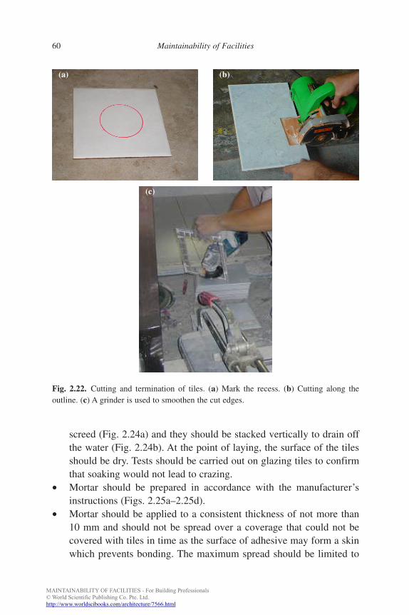
MAINTAINABILITY OF FACILITIES - For Building Professionals© World Scientific Publishing Co. Pte. Ltd.http://www.worldscibooks.com/architecture/7566.html
FA
60 Maintainability of Facilities
screed (Fig. 2.24a) and they should be stacked vertically to drain offthe water (Fig. 2.24b). At the point of laying, the surface of the tilesshould be dry. Tests should be carried out on glazing tiles to confirmthat soaking would not lead to crazing.
• Mortar should be prepared in accordance with the manufacturer’sinstructions (Figs. 2.25a–2.25d).
• Mortar should be applied to a consistent thickness of not more than10 mm and should not be spread over a coverage that could not becovered with tiles in time as the surface of adhesive may form a skinwhich prevents bonding. The maximum spread should be limited to
Fig. 2.22. Cutting and termination of tiles. (a) Mark the recess. (b) Cutting along theoutline. (c) A grinder is used to smoothen the cut edges.
(b)
(c)
(a)
b885_Chapter-02.qxd 12/29/2009 2:35 PM Page 60
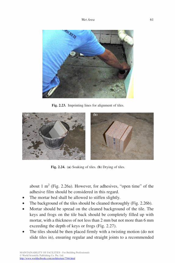
MAINTAINABILITY OF FACILITIES - For Building Professionals© World Scientific Publishing Co. Pte. Ltd.http://www.worldscibooks.com/architecture/7566.html
FA
Wet Area 61
about 1 m2 (Fig. 2.26a). However, for adhesives, “open time” of theadhesive film should be considered in this regard.
• The mortar bed shall be allowed to stiffen slightly.• The background of the tiles should be cleaned thoroughly (Fig. 2.26b).• Mortar should be spread on the cleaned background of the tile. The
keys and frogs on the tile back should be completely filled up withmortar, with a thickness of not less than 2 mm but not more than 6 mmexceeding the depth of keys or frogs (Fig. 2.27).
• The tiles should be then placed firmly with a twisting motion (do notslide tiles in), ensuring regular and straight joints to a recommended
Fig. 2.23. Imprinting lines for alignment of tiles.
Fig. 2.24. (a) Soaking of tiles. (b) Drying of tiles.
(a) (b)
b885_Chapter-02.qxd 12/29/2009 2:35 PM Page 61
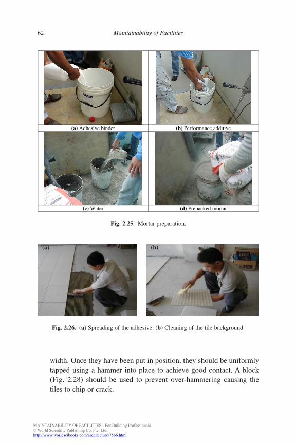
MAINTAINABILITY OF FACILITIES - For Building Professionals© World Scientific Publishing Co. Pte. Ltd.http://www.worldscibooks.com/architecture/7566.html
FA
62 Maintainability of Facilities
width. Once they have been put in position, they should be uniformlytapped using a hammer into place to achieve good contact. A block(Fig. 2.28) should be used to prevent over-hammering causing thetiles to chip or crack.
(a) Adhesive binder (b) Performance additive
(c) Water (d) Prepacked mortar
Fig. 2.25. Mortar preparation.
(a) (b)
Fig. 2.26. (a) Spreading of the adhesive. (b) Cleaning of the tile background.
b885_Chapter-02.qxd 12/29/2009 2:35 PM Page 62
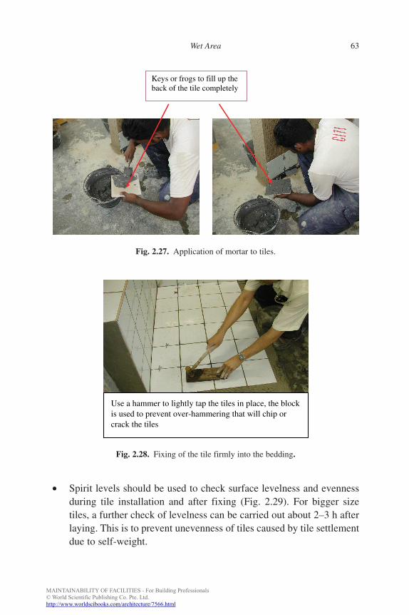
MAINTAINABILITY OF FACILITIES - For Building Professionals© World Scientific Publishing Co. Pte. Ltd.http://www.worldscibooks.com/architecture/7566.html
FA
Wet Area 63
• Spirit levels should be used to check surface levelness and evennessduring tile installation and after fixing (Fig. 2.29). For bigger sizetiles, a further check of levelness can be carried out about 2–3 h afterlaying. This is to prevent unevenness of tiles caused by tile settlementdue to self-weight.
Keys or frogs to fill up the back of the tile completely
Fig. 2.27. Application of mortar to tiles.
Use a hammer to lightly tap the tiles in place, the blockis used to prevent over-hammering that will chip orcrack the tiles
Fig. 2.28. Fixing of the tile firmly into the bedding.
b885_Chapter-02.qxd 12/29/2009 2:35 PM Page 63
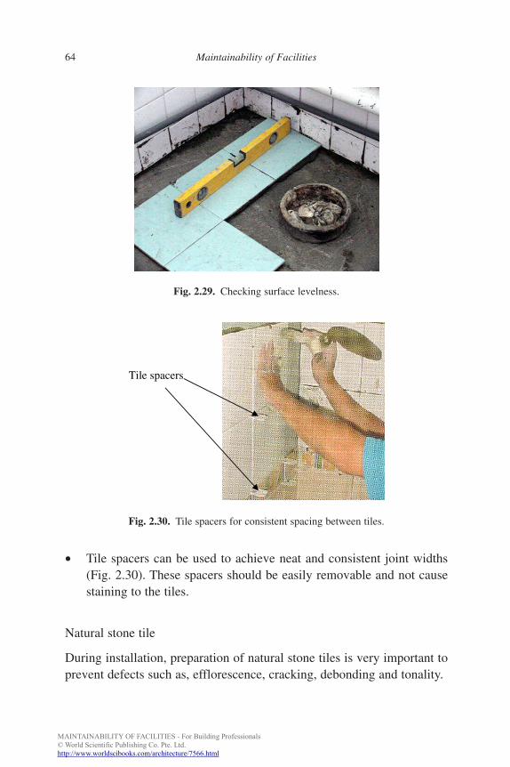
MAINTAINABILITY OF FACILITIES - For Building Professionals© World Scientific Publishing Co. Pte. Ltd.http://www.worldscibooks.com/architecture/7566.html
FA
64 Maintainability of Facilities
• Tile spacers can be used to achieve neat and consistent joint widths(Fig. 2.30). These spacers should be easily removable and not causestaining to the tiles.
Natural stone tile
During installation, preparation of natural stone tiles is very important toprevent defects such as, efflorescence, cracking, debonding and tonality.
Fig. 2.29. Checking surface levelness.
Tile spacers
Fig. 2.30. Tile spacers for consistent spacing between tiles.
b885_Chapter-02.qxd 12/29/2009 2:35 PM Page 64
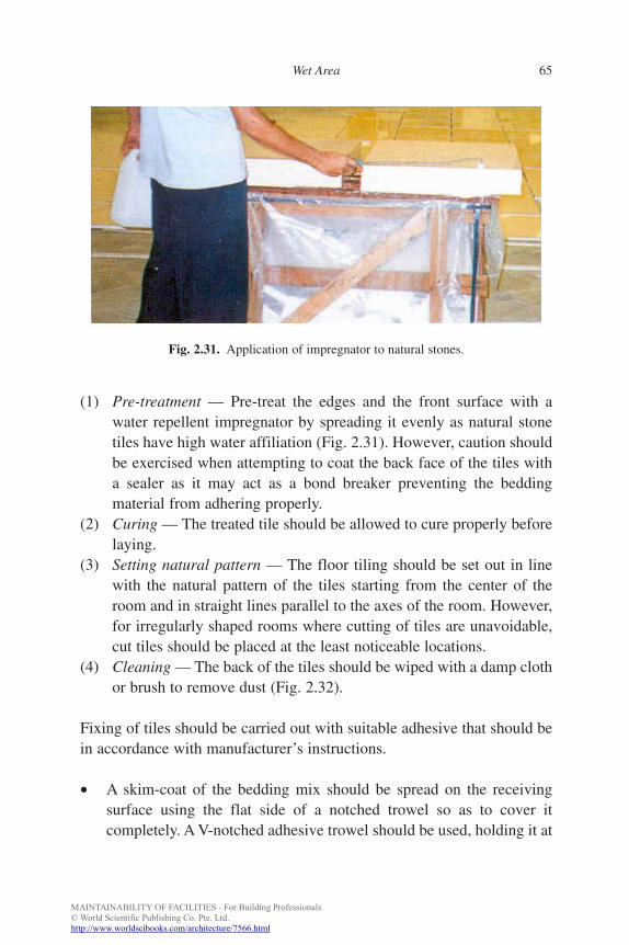
MAINTAINABILITY OF FACILITIES - For Building Professionals© World Scientific Publishing Co. Pte. Ltd.http://www.worldscibooks.com/architecture/7566.html
FA
Wet Area 65
(1) Pre-treatment — Pre-treat the edges and the front surface with awater repellent impregnator by spreading it evenly as natural stonetiles have high water affiliation (Fig. 2.31). However, caution shouldbe exercised when attempting to coat the back face of the tiles witha sealer as it may act as a bond breaker preventing the beddingmaterial from adhering properly.
(2) Curing — The treated tile should be allowed to cure properly beforelaying.
(3) Setting natural pattern — The floor tiling should be set out in linewith the natural pattern of the tiles starting from the center of theroom and in straight lines parallel to the axes of the room. However,for irregularly shaped rooms where cutting of tiles are unavoidable,cut tiles should be placed at the least noticeable locations.
(4) Cleaning — The back of the tiles should be wiped with a damp clothor brush to remove dust (Fig. 2.32).
Fixing of tiles should be carried out with suitable adhesive that should bein accordance with manufacturer’s instructions.
• A skim-coat of the bedding mix should be spread on the receivingsurface using the flat side of a notched trowel so as to cover itcompletely. A V-notched adhesive trowel should be used, holding it at
Fig. 2.31. Application of impregnator to natural stones.
b885_Chapter-02.qxd 12/29/2009 2:35 PM Page 65
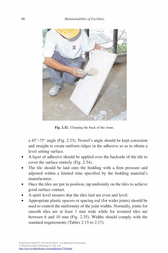
MAINTAINABILITY OF FACILITIES - For Building Professionals© World Scientific Publishing Co. Pte. Ltd.http://www.worldscibooks.com/architecture/7566.html
FA
66 Maintainability of Facilities
Fig. 2.32. Cleaning the back of the stone.
a 45°–75° angle (Fig. 2.33). Trowel’s angle should be kept consistentand straight to create uniform ridges in the adhesive so as to obtain alevel setting surface.
• A layer of adhesive should be applied over the backside of the tile tocover the surface entirely (Fig. 2.34).
• The tile should be laid onto the bedding with a firm pressure andadjusted within a limited time specified by the bedding material’smanufacturer.
• Once the tiles are put in position, tap uniformly on the tiles to achievegood surface contact.
• A spirit level ensures that the tiles laid are even and level.• Appropriate plastic spacers or spacing rod (for wider joints) should be
used to control the uniformity of the joint widths. Normally, joints forsmooth tiles are at least 1 mm wide while for textured tiles arebetween 6 and 10 mm (Fig. 2.35). Widths should comply with thestandard requirements (Tables 2.15 to 2.17).
b885_Chapter-02.qxd 12/29/2009 2:35 PM Page 66
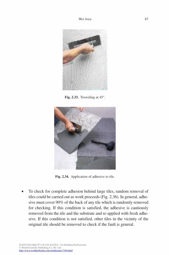
MAINTAINABILITY OF FACILITIES - For Building Professionals© World Scientific Publishing Co. Pte. Ltd.http://www.worldscibooks.com/architecture/7566.html
FA
Wet Area 67
• To check for complete adhesion behind large tiles, random removal oftiles could be carried out as work proceeds (Fig. 2.36). In general, adhe-sive must cover 90% of the back of any tile which is randomly removedfor checking. If this condition is satisfied, the adhesive is cautiouslyremoved from the tile and the substrate and re-applied with fresh adhe-sive. If this condition is not satisfied, other tiles in the vicinity of theoriginal tile should be removed to check if the fault is general.
Fig. 2.33. Troweling at 45°.
Fig. 2.34. Application of adhesive to tile.
b885_Chapter-02.qxd 12/29/2009 2:35 PM Page 67
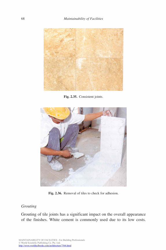
MAINTAINABILITY OF FACILITIES - For Building Professionals© World Scientific Publishing Co. Pte. Ltd.http://www.worldscibooks.com/architecture/7566.html
FA
68 Maintainability of Facilities
Fig. 2.35. Consistent joints.
Fig. 2.36. Removal of tiles to check for adhesion.
Grouting
Grouting of tile joints has a significant impact on the overall appearanceof the finishes. White cement is commonly used due to its low costs.
b885_Chapter-02.qxd 12/29/2009 2:35 PM Page 68
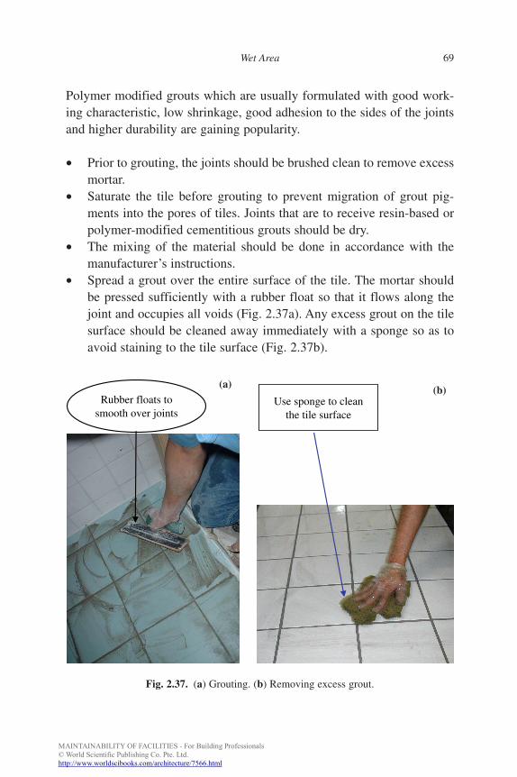
MAINTAINABILITY OF FACILITIES - For Building Professionals© World Scientific Publishing Co. Pte. Ltd.http://www.worldscibooks.com/architecture/7566.html
FA
Wet Area 69
Polymer modified grouts which are usually formulated with good work-ing characteristic, low shrinkage, good adhesion to the sides of the jointsand higher durability are gaining popularity.
• Prior to grouting, the joints should be brushed clean to remove excessmortar.
• Saturate the tile before grouting to prevent migration of grout pig-ments into the pores of tiles. Joints that are to receive resin-based orpolymer-modified cementitious grouts should be dry.
• The mixing of the material should be done in accordance with themanufacturer’s instructions.
• Spread a grout over the entire surface of the tile. The mortar shouldbe pressed sufficiently with a rubber float so that it flows along thejoint and occupies all voids (Fig. 2.37a). Any excess grout on the tilesurface should be cleaned away immediately with a sponge so as toavoid staining to the tile surface (Fig. 2.37b).
Rubber floats tosmooth over joints
Use sponge to cleanthe tile surface
Fig. 2.37. (a) Grouting. (b) Removing excess grout.
(a) (b)
b885_Chapter-02.qxd 12/29/2009 2:36 PM Page 69
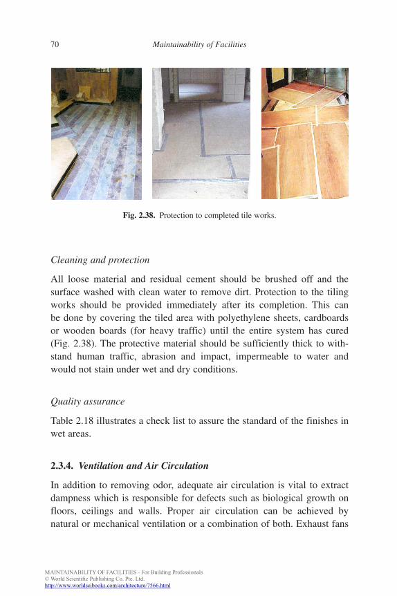
MAINTAINABILITY OF FACILITIES - For Building Professionals© World Scientific Publishing Co. Pte. Ltd.http://www.worldscibooks.com/architecture/7566.html
FA
70 Maintainability of Facilities
Cleaning and protection
All loose material and residual cement should be brushed off and thesurface washed with clean water to remove dirt. Protection to the tilingworks should be provided immediately after its completion. This canbe done by covering the tiled area with polyethylene sheets, cardboardsor wooden boards (for heavy traffic) until the entire system has cured(Fig. 2.38). The protective material should be sufficiently thick to with-stand human traffic, abrasion and impact, impermeable to water andwould not stain under wet and dry conditions.
Quality assurance
Table 2.18 illustrates a check list to assure the standard of the finishes inwet areas.
2.3.4. Ventilation and Air Circulation
In addition to removing odor, adequate air circulation is vital to extractdampness which is responsible for defects such as biological growth onfloors, ceilings and walls. Proper air circulation can be achieved bynatural or mechanical ventilation or a combination of both. Exhaust fans
Fig. 2.38. Protection to completed tile works.
b885_Chapter-02.qxd 12/29/2009 2:36 PM Page 70
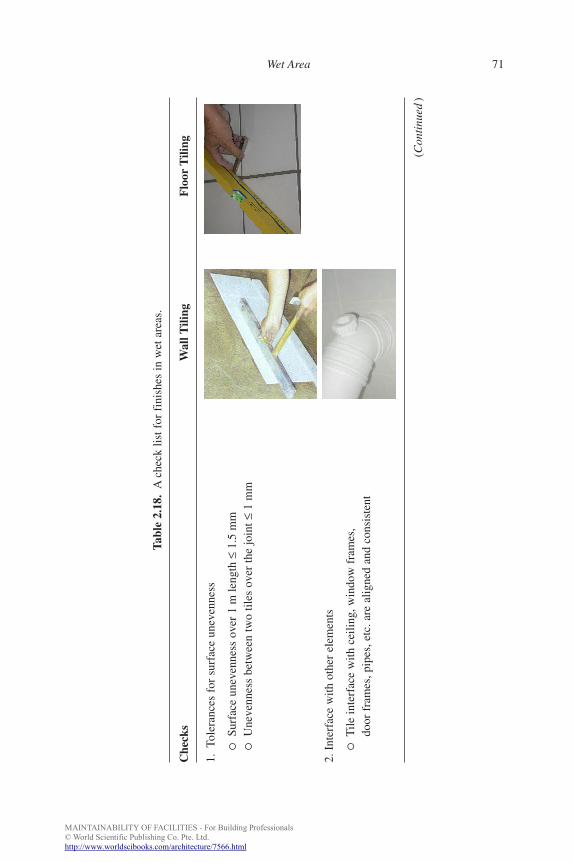
MAINTAINABILITY OF FACILITIES - For Building Professionals© World Scientific Publishing Co. Pte. Ltd.http://www.worldscibooks.com/architecture/7566.html
FA
Wet Area 71
Tabl
e 2.
18.
Ach
eck
list f
or f
inis
hes
in w
et a
reas
.
Che
cks
Wal
l Tili
ngF
loor
Tili
ng
1.To
lera
nces
for
sur
face
une
venn
ess
2. I
nter
face
with
oth
er e
lem
ents
(Con
tinu
ed)
�Su
rfac
e un
even
ness
ove
r 1
m le
ngth
≤1.
5m
m�
Une
venn
ess
betw
een
two
tiles
ove
r th
e jo
int ≤
1m
m
�T
ile in
terf
ace
with
cei
ling,
win
dow
fra
mes
,do
or f
ram
es, p
ipes
, etc
. are
alig
ned
and
cons
iste
nt
b885_Chapter-02.qxd 12/29/2009 2:36 PM Page 71
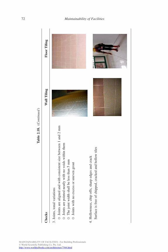
MAINTAINABILITY OF FACILITIES - For Building Professionals© World Scientific Publishing Co. Pte. Ltd.http://www.worldscibooks.com/architecture/7566.html
FA
72 Maintainability of Facilities
Tabl
e 2.
18.
(Con
tinu
ed)
Che
cks
Wal
l Tili
ngF
loor
Tili
ng
3. J
oint
s, to
nal v
aria
tions
4. H
ollo
wne
ss, c
hip
offs
, sha
rp e
dges
and
cra
ck
�Jo
ints
are
alig
ned
and
with
con
sist
ent s
ize
betw
een
1 an
d 2
mm
�Jo
ints
are
poi
nted
nea
tly w
ith n
o vo
ids
with
in th
em�
The
join
t wid
th s
hall
be le
ss th
an 5
mm
�Jo
ints
with
no
exce
ss o
r un
even
gro
ut
Surf
ace
is f
ree
of c
hipp
ed, c
rack
ed a
nd h
ollo
w ti
les
b885_Chapter-02.qxd 12/29/2009 2:36 PM Page 72
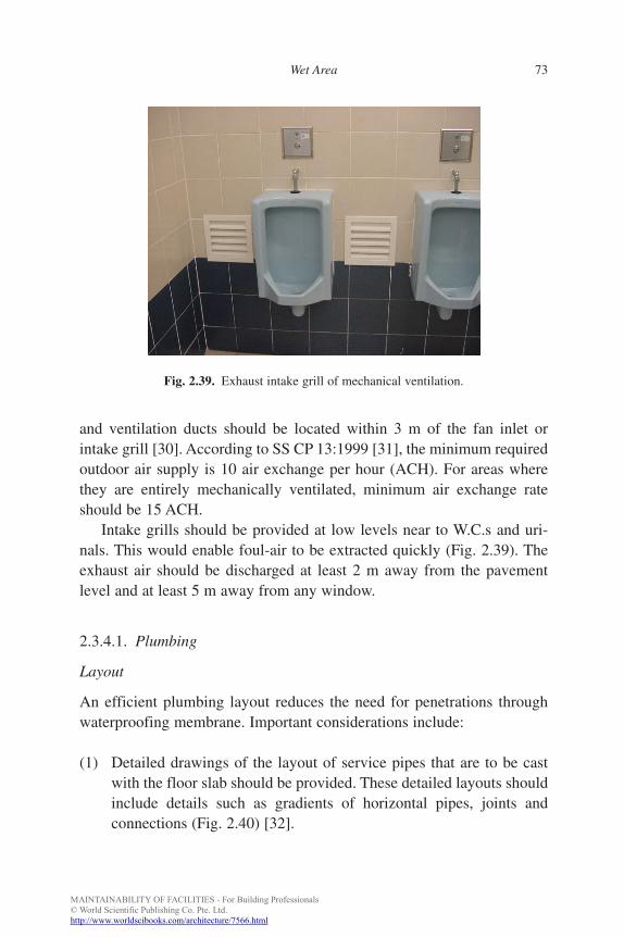
MAINTAINABILITY OF FACILITIES - For Building Professionals© World Scientific Publishing Co. Pte. Ltd.http://www.worldscibooks.com/architecture/7566.html
FA
Wet Area 73
and ventilation ducts should be located within 3 m of the fan inlet orintake grill [30]. According to SS CP 13:1999 [31], the minimum requiredoutdoor air supply is 10 air exchange per hour (ACH). For areas wherethey are entirely mechanically ventilated, minimum air exchange rateshould be 15 ACH.
Intake grills should be provided at low levels near to W.C.s and uri-nals. This would enable foul-air to be extracted quickly (Fig. 2.39). Theexhaust air should be discharged at least 2 m away from the pavementlevel and at least 5 m away from any window.
2.3.4.1. Plumbing
Layout
An efficient plumbing layout reduces the need for penetrations throughwaterproofing membrane. Important considerations include:
(1) Detailed drawings of the layout of service pipes that are to be castwith the floor slab should be provided. These detailed layouts shouldinclude details such as gradients of horizontal pipes, joints andconnections (Fig. 2.40) [32].
Fig. 2.39. Exhaust intake grill of mechanical ventilation.
b885_Chapter-02.qxd 12/29/2009 2:36 PM Page 73
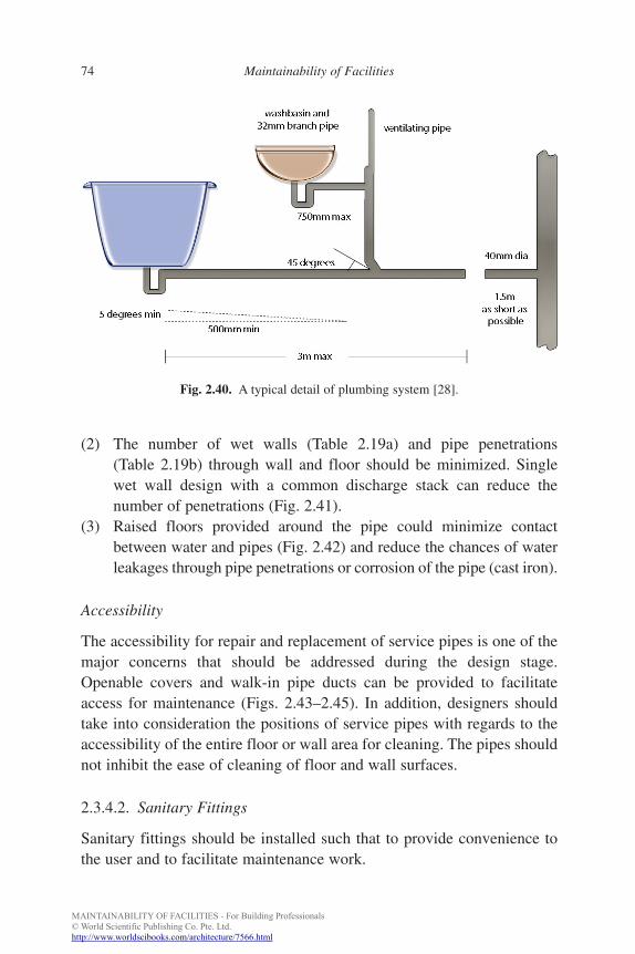
MAINTAINABILITY OF FACILITIES - For Building Professionals© World Scientific Publishing Co. Pte. Ltd.http://www.worldscibooks.com/architecture/7566.html
FA
74 Maintainability of Facilities
(2) The number of wet walls (Table 2.19a) and pipe penetrations(Table 2.19b) through wall and floor should be minimized. Singlewet wall design with a common discharge stack can reduce thenumber of penetrations (Fig. 2.41).
(3) Raised floors provided around the pipe could minimize contactbetween water and pipes (Fig. 2.42) and reduce the chances of waterleakages through pipe penetrations or corrosion of the pipe (cast iron).
Accessibility
The accessibility for repair and replacement of service pipes is one of themajor concerns that should be addressed during the design stage.Openable covers and walk-in pipe ducts can be provided to facilitateaccess for maintenance (Figs. 2.43–2.45). In addition, designers shouldtake into consideration the positions of service pipes with regards to theaccessibility of the entire floor or wall area for cleaning. The pipes shouldnot inhibit the ease of cleaning of floor and wall surfaces.
2.3.4.2. Sanitary Fittings
Sanitary fittings should be installed such that to provide convenience tothe user and to facilitate maintenance work.
Fig. 2.40. A typical detail of plumbing system [28].
b885_Chapter-02.qxd 12/29/2009 2:36 PM Page 74
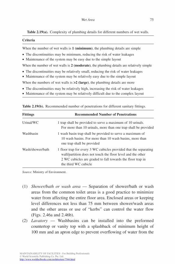
MAINTAINABILITY OF FACILITIES - For Building Professionals© World Scientific Publishing Co. Pte. Ltd.http://www.worldscibooks.com/architecture/7566.html
FA
Wet Area 75
(1) Shower/bath or wash area — Separation of shower/bath or washareas from the common toilet areas is a good practice to minimizewater from affecting the entire floor area. Enclosed areas or keepinglevel differences not less than 75 mm between shower/wash areasand the other areas or use of “kerbs” can control the water flow(Figs. 2.46a and 2.46b).
(2) Lavatory — Washbasins can be installed into the preformedcountertop or vanity top with a splashback of minimum height of100 mm and an apron edge to prevent overflowing of water from the
Table 2.19(a). Complexity of plumbing details for different numbers of wet walls.
Criteria
When the number of wet walls is 1 (minimum), the plumbing details are simple
• The discontinuities may be minimum, reducing the risk of water leakages• Maintenance of the system may be easy due to the simple layout
When the number of wet walls is 2 (moderate), the plumbing details are relatively simple
• The discontinuities may be relatively small, reducing the risk of water leakages• Maintenance of the system may be relatively easy due to the simple layout
When the numbers of wet walls is >>2 (large), the plumbing details are more
• The discontinuities may be relatively high, increasing the risk of water leakages• Maintenance of the system may be relatively difficult due to the complex layout
Table 2.19(b). Recommended number of penetrations for different sanitary fittings.
Fittings Recommended Number of Penetrations
Urinal/WC 1 trap shall be provided to serve a maximum of 10 urinals.For more than 10 urinals, more than one trap shall be provided
Washbasin 1 wash basin trap shall be provided to serve a maximum of10 wash basins. For more than 10 wash basins, more thanone trap shall be provided
Wash/shower/bath 1 floor trap for every 3 WC cubicles provided that the separatingwall/partition does not touch the floor level and the other2 WC cubicles are graded to fall towards the floor trap inthe third WC cubicle
Source: Ministry of Environment.
b885_Chapter-02.qxd 12/29/2009 2:36 PM Page 75
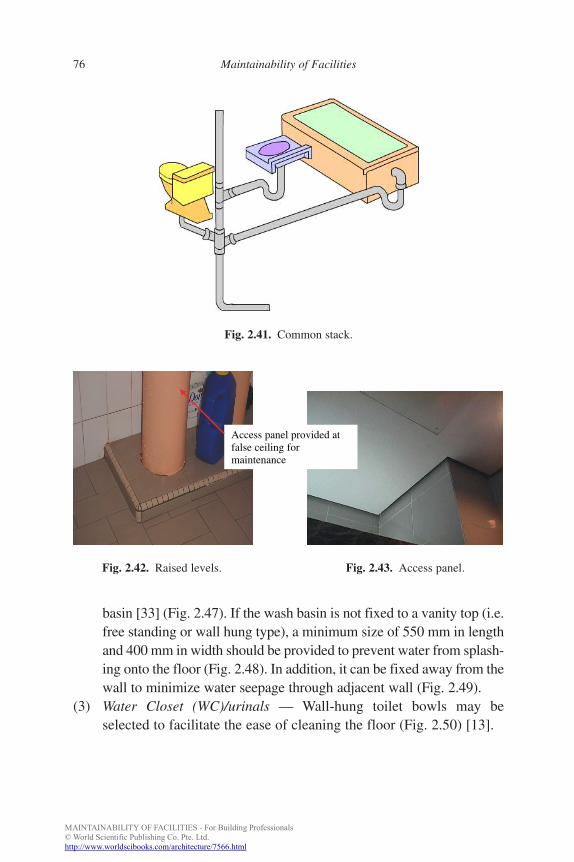
MAINTAINABILITY OF FACILITIES - For Building Professionals© World Scientific Publishing Co. Pte. Ltd.http://www.worldscibooks.com/architecture/7566.html
FA
76 Maintainability of Facilities
basin [33] (Fig. 2.47). If the wash basin is not fixed to a vanity top (i.e.free standing or wall hung type), a minimum size of 550 mm in lengthand 400 mm in width should be provided to prevent water from splash-ing onto the floor (Fig. 2.48). In addition, it can be fixed away from thewall to minimize water seepage through adjacent wall (Fig. 2.49).
(3) Water Closet (WC)/urinals — Wall-hung toilet bowls may beselected to facilitate the ease of cleaning the floor (Fig. 2.50) [13].
Fig. 2.41. Common stack.
Access panel provided at false ceiling for maintenance
Fig. 2.42. Raised levels. Fig. 2.43. Access panel.
b885_Chapter-02.qxd 12/29/2009 2:36 PM Page 76
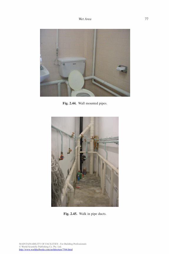
MAINTAINABILITY OF FACILITIES - For Building Professionals© World Scientific Publishing Co. Pte. Ltd.http://www.worldscibooks.com/architecture/7566.html
FA
Wet Area 77
Fig. 2.44. Wall mounted pipes.
Fig. 2.45. Walk in pipe ducts.
b885_Chapter-02.qxd 12/29/2009 2:36 PM Page 77
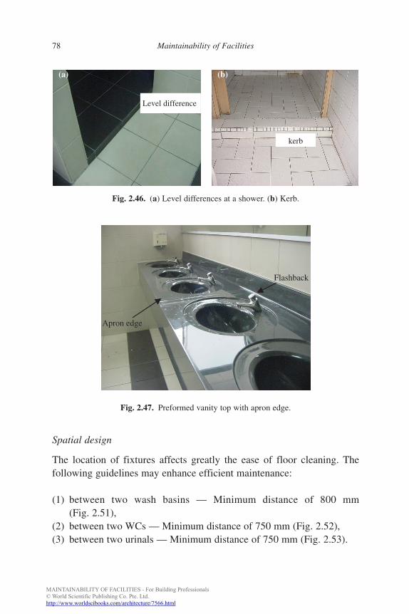
MAINTAINABILITY OF FACILITIES - For Building Professionals© World Scientific Publishing Co. Pte. Ltd.http://www.worldscibooks.com/architecture/7566.html
FA
78 Maintainability of Facilities
Spatial design
The location of fixtures affects greatly the ease of floor cleaning. Thefollowing guidelines may enhance efficient maintenance:
(1) between two wash basins — Minimum distance of 800 mm(Fig. 2.51),
(2) between two WCs — Minimum distance of 750 mm (Fig. 2.52),(3) between two urinals — Minimum distance of 750 mm (Fig. 2.53).
Level difference
kerb
Fig. 2.46. (a) Level differences at a shower. (b) Kerb.
(a) (b)
Flashback
Apron edge
Fig. 2.47. Preformed vanity top with apron edge.
b885_Chapter-02.qxd 12/29/2009 2:36 PM Page 78
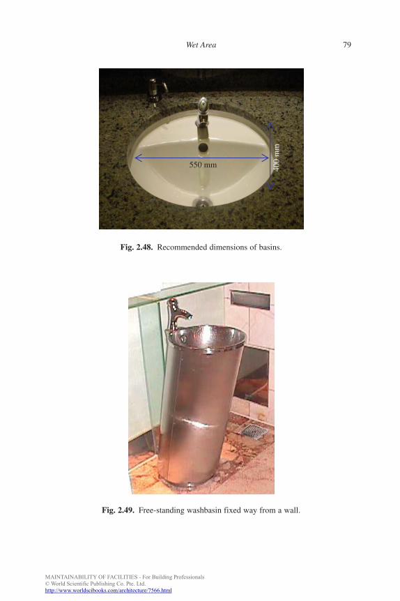
MAINTAINABILITY OF FACILITIES - For Building Professionals© World Scientific Publishing Co. Pte. Ltd.http://www.worldscibooks.com/architecture/7566.html
FA
Wet Area 79
550 mm 400
mm
Fig. 2.48. Recommended dimensions of basins.
Fig. 2.49. Free-standing washbasin fixed way from a wall.
b885_Chapter-02.qxd 12/29/2009 2:36 PM Page 79
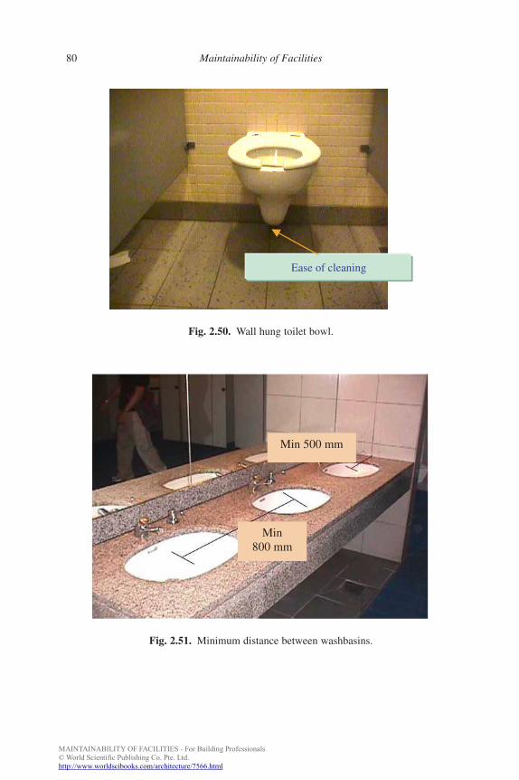
MAINTAINABILITY OF FACILITIES - For Building Professionals© World Scientific Publishing Co. Pte. Ltd.http://www.worldscibooks.com/architecture/7566.html
FA
80 Maintainability of Facilities
Fig. 2.50. Wall hung toilet bowl.
Ease of cleaning
Fig. 2.51. Minimum distance between washbasins.
Min 800 mm
Min 500 mm
b885_Chapter-02.qxd 12/29/2009 2:36 PM Page 80
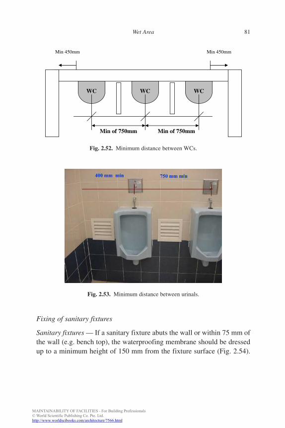
MAINTAINABILITY OF FACILITIES - For Building Professionals© World Scientific Publishing Co. Pte. Ltd.http://www.worldscibooks.com/architecture/7566.html
FA
Wet Area 81
Fixing of sanitary fixtures
Sanitary fixtures — If a sanitary fixture abuts the wall or within 75 mm ofthe wall (e.g. bench top), the waterproofing membrane should be dressedup to a minimum height of 150 mm from the fixture surface (Fig. 2.54).
Fig. 2.52. Minimum distance between WCs.
Min of 750mm Min of 750mm
WC WC WC
Min 450mm Min 450mm
Fig. 2.53. Minimum distance between urinals.
b885_Chapter-02.qxd 12/29/2009 2:36 PM Page 81
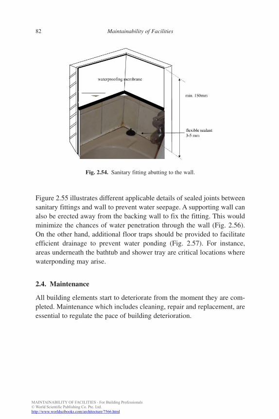
MAINTAINABILITY OF FACILITIES - For Building Professionals© World Scientific Publishing Co. Pte. Ltd.http://www.worldscibooks.com/architecture/7566.html
FA
82 Maintainability of Facilities
Figure 2.55 illustrates different applicable details of sealed joints betweensanitary fittings and wall to prevent water seepage. A supporting wall canalso be erected away from the backing wall to fix the fitting. This wouldminimize the chances of water penetration through the wall (Fig. 2.56).On the other hand, additional floor traps should be provided to facilitateefficient drainage to prevent water ponding (Fig. 2.57). For instance,areas underneath the bathtub and shower tray are critical locations wherewaterponding may arise.
2.4. Maintenance
All building elements start to deteriorate from the moment they are com-pleted. Maintenance which includes cleaning, repair and replacement, areessential to regulate the pace of building deterioration.
Fig. 2.54. Sanitary fitting abutting to the wall.
b885_Chapter-02.qxd 12/29/2009 2:36 PM Page 82
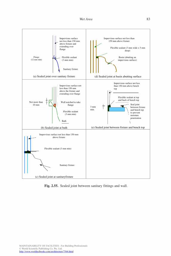
MAINTAINABILITY OF FACILITIES - For Building Professionals© World Scientific Publishing Co. Pte. Ltd.http://www.worldscibooks.com/architecture/7566.html
FA
Wet Area 83
Fig. 2.55. Sealed joint between sanitary fittings and wall.
(a) Sealed joint over sanitary fixture (d) Sealed joint at basin abutting surface
(b) Sealed joint at bath (e) Sealed joint between fixture and bench top
(c) Sealed joint at sanitaryfixture
Impervious surfacenot less than 150 mmabove fixture andextending overflange
Flange(12 mm min)
Flexible sealant(3 mm min)
Sanitary fixture
Impervious surface not less than150 mm above fixture
Flexible sealant (3 mm wide x 5 mmdeep)
Basin (abutting animpervious surface)
Impervious surface not less than 150 mmabove the fixture and extending over flange
Wall notched to takeflange
Flexible sealant(3 mm min)
Bath
Not more than10 mm
Impervious surface not lessthan 150 mm above bench top
Flexible sealant at top and back of bench top
3 mmmin.
Seal joint between fixture and bench top to preventmoisture penetration
Impervious surface not less than 150 mmabove fixture
Flexible sealant (3 mm min)
Sanitary fixture
b885_Chapter-02.qxd 12/29/2009 2:36 PM Page 83
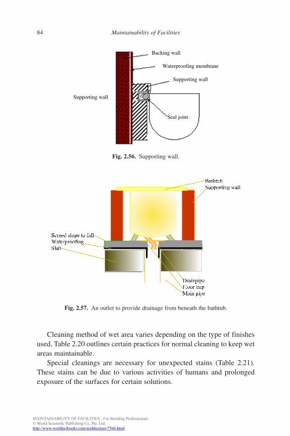
MAINTAINABILITY OF FACILITIES - For Building Professionals© World Scientific Publishing Co. Pte. Ltd.http://www.worldscibooks.com/architecture/7566.html
FA
84 Maintainability of Facilities
Fig. 2.57. An outlet to provide drainage from beneath the bathtub.
Fig. 2.56. Supporting wall.
Backing wall
Waterproofing membrane
Supporting wall
Seal joint
Supporting wall
Cleaning method of wet area varies depending on the type of finishesused. Table 2.20 outlines certain practices for normal cleaning to keep wetareas maintainable.
Special cleanings are necessary for unexpected stains (Table 2.21).These stains can be due to various activities of humans and prolongedexposure of the surfaces for certain solutions.
b885_Chapter-02.qxd 12/29/2009 2:36 PM Page 84
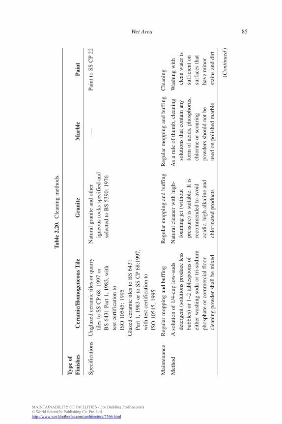
MAINTAINABILITY OF FACILITIES - For Building Professionals© World Scientific Publishing Co. Pte. Ltd.http://www.worldscibooks.com/architecture/7566.html
FA
Wet Area 85
Tabl
e 2.
20.
Cle
anin
g m
etho
ds.
Typ
e of
Fin
ishe
sC
eram
ic/H
omog
eneo
us T
ileG
rani
teM
arbl
eP
aint
Spec
ific
atio
nsU
ngla
zed
cera
mic
tile
s or
qua
rry
Nat
ural
gra
nite
and
oth
er
—Pa
int t
o SS
CP
22til
es to
SS
CP
68: 1
997
orig
neou
s ro
cks
spec
ifie
d an
dB
S 64
31 P
art 1
, 198
3, w
ithse
lect
ed to
BS
5390
: 197
6te
st c
ertif
icat
ion
toIS
O 1
0545
: 199
5G
laze
d ce
ram
ic ti
les
to B
S 64
31Pa
rt 1
, 198
3 or
to S
S C
P68
:199
7,w
ith te
st c
ertif
icat
ion
toIS
O 1
0545
, 199
5
Mai
nten
ance
Reg
ular
mop
ping
and
buf
fing
Reg
ular
mop
ping
and
buf
fing
Reg
ular
mop
ping
and
buf
fing
Cle
anin
g
Met
hod
Aso
lutio
n of
1/4
-cup
low
-sud
sN
atur
al c
lean
er w
ith h
igh-
As
a ru
le o
f th
umb,
cle
anin
gW
ashi
ng w
ithde
terg
ent (
solu
tions
pro
duce
less
foam
ing
jet (
with
out
solu
tions
that
con
tain
any
clea
n w
ater
isbu
bble
s) o
r 1–
2 ta
bles
poon
s of
pres
sure
) is
sui
tabl
e. I
t is
form
of
acid
s, p
hosp
horu
s,su
ffic
ient
on
eith
er w
ashi
ng s
oda
or tr
i-so
dium
reco
mm
ende
d to
avo
idch
lori
ne o
r sc
ouri
ngsu
rfac
es th
atph
osph
ate
or c
omm
erci
al f
loor
acid
ic, h
igh
alka
line
and
pow
ders
sho
uld
not b
e ha
ve m
inor
clea
ning
pow
der
shal
l be
mix
edch
lori
nate
d pr
oduc
tsus
ed o
n po
lishe
d m
arbl
est
ains
and
dir
t
(Con
tinu
ed)
b885_Chapter-02.qxd 12/29/2009 2:36 PM Page 85
MAINTAINABILITY OF FACILITIES - For Building Professionals© World Scientific Publishing Co. Pte. Ltd.http://www.worldscibooks.com/architecture/7566.html
FA
86 Maintainability of Facilities
Tabl
e 2.
20.
(Con
tinu
ed)
Typ
e of
Fin
ishe
sC
eram
ic/H
omog
eneo
us T
ileG
rani
teM
arbl
eP
aint
wel
l in
1 ga
llon
wat
er to
cle
anH
owev
er, d
ry c
lean
ing
Thi
s w
ould
mak
e m
arbl
e If
nec
essa
ry,
the
floo
rm
etho
ds a
re r
ecom
men
ded
look
s du
ll or
suf
fer
from
a
mild
det
erge
ntov
er f
requ
ent w
et c
lean
ing
peel
ing
effe
ct k
now
n as
m
ay b
e us
edm
etho
ds in
wet
are
a“o
rang
e pe
el”
unle
ssfo
r he
avy
adhe
ring
to th
e ca
utio
ns
stai
nsan
d/or
for
mul
as p
rovi
ded.
In
add
ition
, any
type
of
abra
sive
pro
duct
sho
uld
also
be
avoi
ded,
in o
rder
to
pre
vent
scr
atch
es a
nd
loss
of
shin
e
For
polis
hed
fini
shin
g sm
all
Plai
n w
ater
can
be
used
to r
emov
ear
eas,
use
of
war
m w
ater
dirt
. How
ever
, for
hea
vier
soi
ling,
wou
ld b
e su
ffic
ient
for
a m
ild d
eter
gent
sol
utio
n is
peri
odic
cle
anin
gre
com
men
ded.
The
sol
utio
n sh
all
(Con
tinu
ed)
b885_Chapter-02.qxd 12/29/2009 2:36 PM Page 86
MAINTAINABILITY OF FACILITIES - For Building Professionals© World Scientific Publishing Co. Pte. Ltd.http://www.worldscibooks.com/architecture/7566.html
FA
Wet Area 87
Tabl
e 2.
20.
(Con
tinu
ed)
Typ
e of
Fin
ishe
sC
eram
ic/H
omog
eneo
us T
ileG
rani
teM
arbl
eP
aint
be w
ell-
mix
ed b
efor
e us
ing.
The
surf
ace
shou
ld th
en b
e ke
pt d
ryfo
r m
ore
shin
e
Cle
anin
gR
esid
enti
al: T
wic
e a
wee
kR
esid
enti
al: T
wic
e a
wee
kR
esid
enti
al:T
wic
e a
wee
kN
o fr
eque
ntfr
eque
ncy
cycl
esC
omm
erci
al a
nd i
nsti
tute
s:
Com
mer
cial
and
ins
titu
tes:
Com
mer
cial
and
ins
titu
tes:
Thr
ee ti
mes
a d
ayT
hree
tim
es a
day
Thr
ee ti
mes
a d
ayO
ffic
es a
nd i
ndus
tria
l: Tw
ice
a da
yO
ffic
es a
nd i
ndus
tria
l: Tw
ice
Off
ices
and
ind
ustr
ial:
Twic
ea
day
a da
y
b885_Chapter-02.qxd 12/29/2009 2:36 PM Page 87
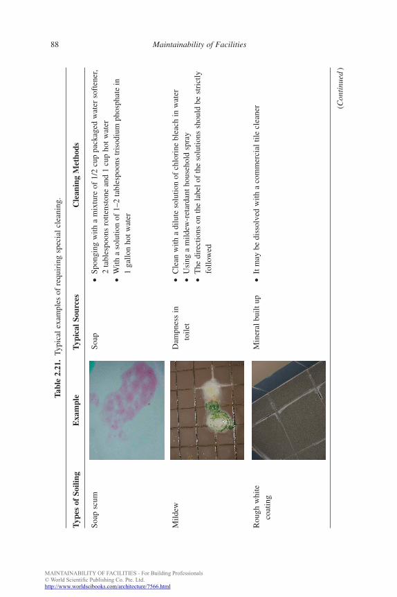
MAINTAINABILITY OF FACILITIES - For Building Professionals© World Scientific Publishing Co. Pte. Ltd.http://www.worldscibooks.com/architecture/7566.html
FA
88 Maintainability of Facilities
Tabl
e 2.
21.
Typi
cal e
xam
ples
of
requ
irin
g sp
ecia
l cle
anin
g.
Typ
es o
f So
iling
Exa
mpl
eT
ypic
al S
ourc
esC
lean
ing
Met
hods
Soap
scu
mSo
ap•
Spon
ging
with
a m
ixtu
re o
f 1/
2 cu
p pa
ckag
ed w
ater
sof
tene
r,2
tabl
espo
ons
rotte
nsto
ne a
nd 1
cup
hot
wat
er•
With
a s
olut
ion
of 1
–2 ta
bles
poon
s tr
isod
ium
pho
spha
te in
1ga
llon
hot w
ater
Mild
ewD
ampn
ess
in•
Cle
an w
ith a
dilu
te s
olut
ion
of c
hlor
ine
blea
ch in
wat
erto
ilet
•U
sing
a m
ildew
-ret
arda
nt h
ouse
hold
spr
ay•
The
dir
ectio
ns o
n th
e la
bel o
f th
e so
lutio
ns s
houl
d be
str
ictly
follo
wed
Rou
gh w
hite
Min
eral
bui
lt up
•It
may
be
diss
olve
d w
ith a
com
mer
cial
tile
cle
aner (C
onti
nued
)
coat
ing
b885_Chapter-02.qxd 12/29/2009 2:36 PM Page 88
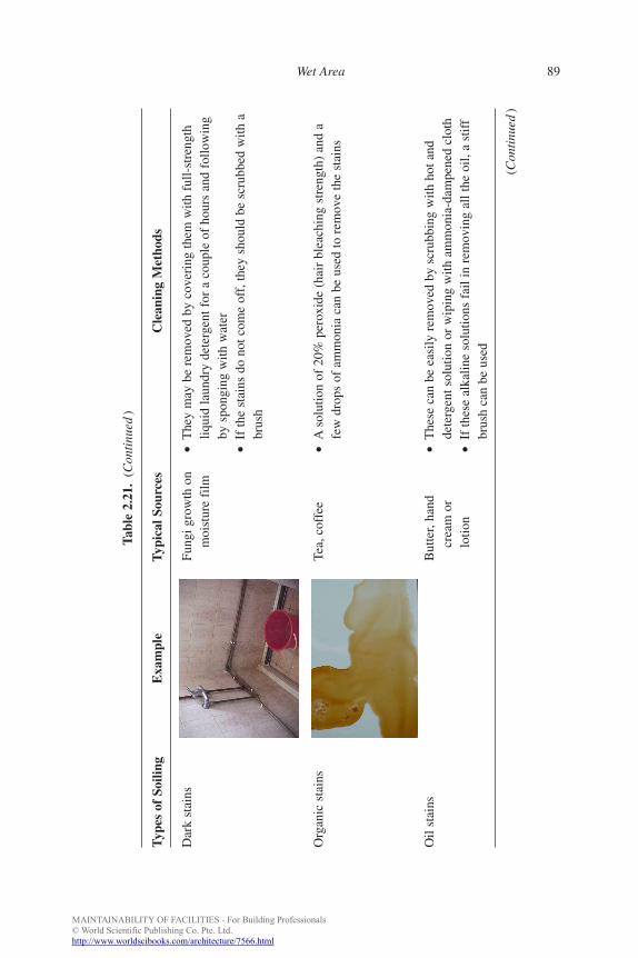
MAINTAINABILITY OF FACILITIES - For Building Professionals© World Scientific Publishing Co. Pte. Ltd.http://www.worldscibooks.com/architecture/7566.html
FA
Wet Area 89
Tabl
e 2.
21.
(Con
tinu
ed)
Typ
es o
f So
iling
Exa
mpl
eT
ypic
al S
ourc
esC
lean
ing
Met
hods
Dar
k st
ains
Fung
i gro
wth
on
•T
hey
may
be
rem
oved
by
cove
ring
them
with
ful
l-st
reng
thm
oist
ure
film
liq
uid
laun
dry
dete
rgen
t for
a c
oupl
e of
hou
rs a
nd f
ollo
win
gby
spo
ngin
g w
ith w
ater
•If
the
stai
ns d
o no
t com
e of
f, th
ey s
houl
d be
scr
ubbe
d w
ith a
brus
h
Org
anic
sta
ins
Tea,
cof
fee
•A
solu
tion
of 2
0% p
erox
ide
(hai
r bl
each
ing
stre
ngth
) an
d a
few
dro
ps o
f am
mon
ia c
an b
e us
ed to
rem
ove
the
stai
ns
Oil
stai
nsB
utte
r, ha
nd•
The
se c
an b
e ea
sily
rem
oved
by
scru
bbin
g w
ith h
ot a
ndcr
eam
or
dete
rgen
t sol
utio
n or
wip
ing
with
am
mon
ia-d
ampe
ned
clot
hlo
tion
•If
thes
e al
kalin
e so
lutio
ns f
ail i
n re
mov
ing
all t
he o
il, a
stif
fbr
ush
can
be u
sed
(Con
tinu
ed)
b885_Chapter-02.qxd 12/29/2009 2:36 PM Page 89
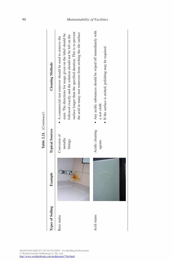
MAINTAINABILITY OF FACILITIES - For Building Professionals© World Scientific Publishing Co. Pte. Ltd.http://www.worldscibooks.com/architecture/7566.html
FA
90 Maintainability of Facilities
Tabl
e 2.
21.
(Con
tinu
ed)
Typ
es o
f So
iling
Exa
mpl
eT
ypic
al S
ourc
esC
lean
ing
Met
hods
Rus
t sta
ins
Cor
rosi
on o
f•
Aco
mm
erci
al r
ust r
emov
er s
houl
d be
use
d to
rem
ove
the
met
allic
st
ain.
The
dir
ectio
ns f
or u
sage
giv
en o
n th
e la
bel s
houl
d be
fitti
ngs
follo
wed
exa
ctly
and
the
solu
tion
shou
ld n
ot b
e le
ft o
n th
esu
rfac
e lo
nger
than
the
spec
ifie
d du
ratio
n. T
his
is to
pre
vent
the
acid
in m
any
rust
rem
over
s fr
om e
tchi
ng th
e til
e su
rfac
e
Aci
d st
ains
Aci
dic
clea
ning
•A
ny a
cidi
c su
bsta
nces
sho
uld
be w
iped
off
imm
edia
tely
with
ag
ents
a w
et c
loth
•If
the
surf
ace
is e
tche
d, p
olis
hing
may
be
requ
ired
b885_Chapter-02.qxd 12/29/2009 2:36 PM Page 90
MAINTAINABILITY OF FACILITIES - For Building Professionals© World Scientific Publishing Co. Pte. Ltd.http://www.worldscibooks.com/architecture/7566.html
FA
Wet Area 91
References
[1] M. Y. L. Chew and N. De Siva, “Maintainability problems of wet areas in
high-rise residential buildings”, Building Research and Information, 31(1),
60–69, 2003.
[2] M. Y. L. Chew, D. S. Nayanthara and S. S. Tan, “Handbook for wet area”,
http://www.hpbc.bdg.nus.edu.sg/, under the segment “About Us” and
“Publication”.
[3] M. Y. L. Chew, Construction Technology for Tall Buildings, 3rd Edition,
World Scientific, Singapore, 2009.
[4] Building and Construction Authority, Good Industry Practices —
Waterproofing for Internal Wet Areas, Singapore, 2001.
[5] British Standards, BS 8204-Part 1: Screeds, Bases and in-situ Floorings.
Concrete Bases and Cement Sand Levelling Screeds to Receive Floorings.
Code of Practice, British Standards Institution, London, 2002.
[6] British Standards, BS 8204-Part 2: Screeds, Bases and in-situ Floorings.
Concrete Wearing Surfaces. Code of Practice, British Standards Institution,
London, 2002.
[7] M. J. Gatfield, Screeds, Flooring and Finishes: Selection, Construction
and Maintenance, Construction Industry Research and Information
Association, London, 1998.
[8] Building and Construction Authority, Good Industry Practices — Ceramic
Tiling, Singapore, 2000.
[9] Building and Construction Authority, Good Industry Practices — Marble
and Granite Tiling, Singapore, 2000.
[10] British Standards, BS EN 12004 Adhesives for Tiles. Definitions and
Specifications, British Standards Institution, London, 2001.
[11] Housing Development Board, HDB Standard Specifications, Singapore,
2003.
[12] M. Y. L. Chew and N. De Silva, “Factors affecting water-tightness in wet
area of high-rise residential buildings”, Architectural Science Review,
45(4), 375–383, 2002.
[13] B. A. Richardson, Defects and Deterioration in Buildings, E&FN Spon,
New York, 2001.
[14] N. L. Mohinder, Piping Handbook, 7th Edition, McGraw Hill, New York,
2000.
b885_Chapter-02.qxd 12/29/2009 2:36 PM Page 91
MAINTAINABILITY OF FACILITIES - For Building Professionals© World Scientific Publishing Co. Pte. Ltd.http://www.worldscibooks.com/architecture/7566.html
FA
92 Maintainability of Facilities
[15] D. A. Willoughby, R. D. Woodson and R. Sutherland, Plastic Piping
Handbook, McGraw Hill, New York, 2002.
[16] Building and Construction Authority, Good Industry Practices —
Waterproofing for Internal Wet Areas, Singapore, 2001.
[17] Standards Australia, AS 3740: Waterproofing Wet Areas within Residential
Buildings, Standards Australia International Ltd, Sydney, 1994.
[18] M. T. Kubal, Construction Waterproofing Handbook, McGraw Hill,
New York, 2000.
[19] Singapore Standards, CP 82 — Code of Practice for Waterproofing of
Reinforced Concrete Buildings, Singapore Standards, Productivity and
Innovation Board, Singapore, 1999.
[20] American Concrete Institute, “Guide to the use of waterproofing, damp-
proofing, protective and decorative barrier systems for concrete”, reported
by ACI Committee 515, Detroit, 1988.
[21] P. W. Pye and H. W. Harrison, Floor and Flooring: Performance,
Diagnosis, Maintenance, Repair and the Avoidance of Defects, Building
Research Establishment, London, 1997.
[22] M. J. Gatfield, Screeds, Flooring and Finishes: Selection, Construction and
Maintenance, Construction Industry Research and Information
Association, London, 1998.
[23] Singapore Standards, CP 68 — Code of Practice for Ceramic Wall and
Floor Tiling, Singapore Standards, Productivity and Innovation Board,
Singapore, 1997.
[24] British Standards, BS 8000: Part 9, Code of Practice for Workmanship on
Building Site: Cementitious Leveling Screeds and Wearing Screeds, British
Standards Institution, London, 1989.
[25] British Standards, BS 8000 Part 11.1, Workmanship on Building Sites:
Code of Practice for Wall and Floor Tiling; Ceramic Tiles, Terrazzo Tiles
and Mosaics, British Standards Institution, London, 1989.
[26] British Standards, BS 5385: Part 1, Wall and Floor Tiling. Code of Practice
for the Design and Installation of Internal Ceramic and Natural Stone Wall
Tiling and Mosaics in Normal Conditions, British Standards Institution,
London, 1995.
[27] British Standards, BS 5385: Part 3, Wall and Floor Tiling. Code of Practice
for the Design and Installation of Ceramic Floor Tiles and Mosaics, British
Standards Institution, London, 1985.
b885_Chapter-02.qxd 12/29/2009 2:36 PM Page 92
MAINTAINABILITY OF FACILITIES - For Building Professionals© World Scientific Publishing Co. Pte. Ltd.http://www.worldscibooks.com/architecture/7566.html
[28] British Standards, BS 5385: Part 4, Wall and Floor Tiling. Code of Practice
for Tiling and Mosaics in Specific Conditions, British Standards Institution,
London, 1992.
[29] British Standards, BS 5385: Part 5, Wall and Floor Tiling. Code of Practice
for the Design and Installation of Terrazzo Tile and Slab, Natural Stone and
Composition Block Floorings, British Standards Institution, London, 1994.
[30] Ministry of Environment, Guidebook for Better Public Toilet-Design and
Maintenance, Singapore, 1999.
[31] Singapore Standards, CP 13 — Code of Practice for Mechanical Ventilation
Air-Conditioning in Buildings, Singapore Standards, Productivity and
Innovation Board, Singapore, 1999.
[32] British Standards, BS-EN 12056-2: Gravity Drainage Systems Inside
Buildings Part 2: Sanitary Pipe Work, Layout and Calculation, British
Standards Institution, London, 2000.
[33] British Standards, BS 6340: Part 3, Shower Units. Specification for
Prefabricated Shower Enclosures and Shower Cabinets, British Standards
Institution, London, 1985.
FA
Wet Area 93
b885_Chapter-02.qxd 12/29/2009 2:36 PM Page 93


