Embed Size (px)
Citation preview
The Feasibility Study on The Development of Dedicated Freight Corridor for Delhi-Mumbai and Delhi-Howrah in India Final Report (Task2)
7.5 TRACK
7.5.1 General
(1) Typical track structure
The typical type of track structure adopted by the Indian Railways is ballasted track.
Typical profile of ballast track structure is shown in Figure 7-31 and Figure 7-32.
The Study Team observed that the track is well maintained. Track irregularity and mud pumping are few on tracks during the site investigation.
The Indian Government established the Special Railway Safety Fund (SRSF) to ensure security of railways and strengthening of railway infrastructure. SRSF amounting to Rs.17,000 Cr. were allocated to liquidate arrears of replacement of assets including track. After creation of this fund, track renewal work got a boost. According to Year Book 2004-2005, track renewal of 5,500 km length was carried out in 2004-05.
The track improvement works include replacement of 52 kg rail with 60 kg rail and replacement of wooden sleepers with PSC (Prestressed concrete) sleepers for lines with high speed and heavy axle load operation.
Figure 7-31 Ballast Profile for LWR Track (Single Line B.G)
Chapter 7 7-60

The Feasibility Study on The Development of Dedicated Freight Corridor for Delhi-Mumbai and Delhi-Howrah in India Final Report (Task2)
Figure 7-32 Standard Ballast Profile for B.G. (Other than LWR/CWR)
(2) Track structure of DFC
For DFC lines, as per the modified terms of reference, track structure shall be made fit for 25 ton axle load and bridges for 30 ton axle load. Indian Railway has an experience of 22.9 ton axle load transported on some lines. The technical detailing for 25 ton axle load may be estimated from 22.9 ton axle load experience, but the technical detailing for future 30 ton axle load should be studied in depth. The track structure is easy to replace and it will deteriorate due to its use and passage of time. So it is proper to construct the track structure of DFC line with 25 ton axle load with provision to improve the track when 30 ton axle load operation is required.
7.5.2 Relationship between Axle Load and Rail Material
(1) Worldwide specifications for Heavy Axle Load Track
A recent innovation has been the introduction of HH rails (Head Hardened Rails) which are particularly suitable for railway conditions involving heavy wear, such as curved track, restricted access locations, or where there are heavy axle loadings. These HH rails are produced to a restricted chemical composition and the head of the rail is heat treated by a two-stage induction heating process followed by a high pressure air quench.
The innovated wheel-rail technologies embraces wear and lubrication, rail corrugations, rolling contact fatigue and thermal/mechanical defects, control of wheel-rail interaction by fine-tuning wheel and rail profiles, rail grinding, friction management and rail and wheel materials.
Chapter 7 7-61

The Feasibility Study on The Development of Dedicated Freight Corridor for Delhi-Mumbai and Delhi-Howrah in India Final Report (Task2)
The stress of rail increases according to the increase of axle load. There is an obvious increasing trend of hardness with increasing axle load with axle load above 26 ton being associated with rail hardness above 320HB. Harder steel is used for curve track to counter the effects of flange contact (wear) and material flow and rolling contact fatigue. These phenomena are the result of high contact stresses and lateral creep generated by the action of the wheels and shape of contact between wheel and rail profiles. The trend towards harder materials in curves is seen. In addition, for axle loads in excess of 26 ton, it is apparent that steel with hardness in excess of 350HB is preferred. The tensile strength of HH rail (JIS E1120) is about 1,100 N/mm2.
Some high axle load railways in North America and Australia use HH rails, whose head is heat-treated because high axle load requires stronger rail.
(2) Specification for Rail
The hardness of the rail and wheel materials affects its life through the interaction of the rail and the wheel. The specification of Japanese and Indian rails is as follows.
1) Japanese Rail specification Table 7-14 Type of Japanese rail
Type Code Weight (kg/m) 50kgN Rail 50N 50.4 60kg Rail 60 60.8
Table 7-15 Chemical composition of non-treated rail
Type C Si Mn P S 50kgN 0.10 - 0.30 60kg
0.60 - 0.75 0.13 - 0.30
0.70 - 1.10 Less than 0.035 Less than 0.040
Table 7-16 Mechanical Properties of non-treated rail
Type Tensile strength kgf/mm2 [N/mm2]
Elongation %
50N Rail More than 8 60kg Rail
More than 80 [784] More than 10
Table 7-17 Chemical composition of Head hardened Rail (JIS E1120)
Chemical composition Type C
% Si %
Mn %
P %
S %
Cr %
V %
HH340 0.10 - 0.55 0.70 – 1.10 HH370
0.72 - 0.82 0.10 - 0.65 0.80 – 1.20
0.030 max.
0.020 max.
0.20 max.
0.03 max.
Hardness of rail head shall be HS47 to HS53 in Shore hardness or HB 321 to HB375 in Brinell hardness.
Table 7-18 Mechanical properties of Head hardened Rail
Type Tensile strength N/mm2 [kgf/mm2]
Elongation %
HH340 1,080 [110] min. HH370 1,130 [115] min.
8 min.
Chapter 7 7-62

The Feasibility Study on The Development of Dedicated Freight Corridor for Delhi-Mumbai and Delhi-Howrah in India Final Report (Task2)
Table 7-19 Surface hardness of vertex part of Head hardened Rail
Type Shore hardness HSC
HH340 47 – 53 HH370 49 – 56
2) Indian Rail (IRS T-12) specification
Table 7-20 Profile of Indian Rail
Profile Sectional Wt kg/m R - 52 51.89 R - 60 60.30
Table 7-21 Specification
Chemical Composition % Mechanical Properties Specification Grade
C M P S Si TS MPa Elong % IRS-T12/96 880 0.60-
0.80 0.80- 1.30
0.035 max
0.035 max
0.10- 0.50 880 min 10.0
Hydrogen content<3 ppm and Al max 0.02% Unit Tensile Strength; 90
Chapter 7 7-63

The Feasibility Study on The Development of Dedicated Freight Corridor for Delhi-Mumbai and Delhi-Howrah in India Final Report (Task2)
3) Comparison of Japanese and Indian rail Table 7-22 Comparison of Japanese rail and Indian one
Type C
% Si %
Mn %
P %
S %
Tensile St. kgf/mm2 [N/mm2]
Elongation %
60kg 0.60- 0.75
0.13- 0.30
0.70- 1.10
Less than 0.035
Less than 0.040
More than 80 [784]
More than 10
JIS
HH340 0.72- 0.82
0.10- 0.55
0.70- 1.10
Less than 0.030
Less than 0.020
More than 110 [1,080] More than 8
IRS T-12 0.60- 0.80
0.10- 0.50
0.80- 1.30
Less than 0.035
Less than 0.035
More than 90 [880] 10.0
4) Wheels on Rolling Stock
Table 7-23 Japanese (JIS (E5402-1))
Grade
Rolled Forged
C max (%)
Mn Max(%)
P Max(%)
S
(%)
Si Max(%)
Tensile Strength (N/mm2)
Elon- gation
(%) C44GW-N-A GC44GW-N-A 600- 720 18- 9 C44GW-T-A GC44GW-T-A 0.46 0.90 0.04 0.04 0.40
770- 890 15-8 C48GW-N-A GC48GW-N-A 630- 750 17- 8 C48GW-T-A GC48GW-T-A 0.50 0.90 0.04 0.04 0.40
820- 940 14-7 C51GW-N-A GC51GW-N-A 660- 800 15- 7 C51GW-T-A GC51GW-T-A 0.54 0.90 0.04 0.04 0.40
860- 980 13-6 C55GW-N-A GC55GW-N-A 700- 840 14- 6 C55GW-T-A GC55GW-T-A 0.58 0.90 0.04 0.04 0.40
900-1050 12-5 C64GW-N-A GC64GW-N-A 800- 940 11- 5 C64GW-T-A GC64GW-T-A 0.67 0.90 0.04 0.04 0.40
940-1140 11-4 C74GW-N-A GC74GW-N-A 830- 1000 9-4 C74GW-T-A GC74GW-T-A 0.77 0.90 0.04 0.04 0.40
1040-1240 9-3
Table 7-24 Indian (IRS)
C Max (%)
Mn
(%)
P Max(%)
S
(%)
Si
(%)
H Max
(ppm)
Tensile Strength (N/mm2)
Elongation (%)
IRS: R-34/99
Diesel Loco Wheels 0.52 0.60-
0.85 0.03 0.03 0.15 2.5 775- 900 (at web) 11- 13
IRS: R19/93
BG Coach & Other wheels
0.57- 0.67
0.60- 0.80 0.03 0.03 0.15- 3 820- 940 14-
IRS: R-16/95
Axles 0.37 -1.12 0.04 0.04 0.15- - 550- 650 25-
Chapter 7 7-64

The Feasibility Study on The Development of Dedicated Freight Corridor for Delhi-Mumbai and Delhi-Howrah in India Final Report (Task2)
Table 7-25 American (AAR (M-107))
Grade C
Max(%)
Mn
(%)
P Max(%)
S Max(%)
Si Min (%)
Brinell Hardness
Class U General Service where an untreated wheel is satisfactory.
0.65- 0.77 -
Class L High speed service with more severe braking conditions than other classes and light wheel loads.
-0.47 197-277
Class A High speed service with severe braking conditions, but with moderate wheel loads.
0.47- 0.57 255-321
Class B High speed service with severe braking conditions and heavier wheel loads.
0.57- 0.67 277-341
Class C Service with light braking conditions and high wheel loads. Service with heavier braking conditions where off-tread brakes are employed.
0.67- 0.77
0.60- 0.85 0.05 0.05 0.15
321-363
7.5.3 Track structure for DFC
(1) Rail
Indian Railways normally uses 60 or 52 g/m 90 kgf/mm2 UTS rails in main lines. Standard 13 m rail are welded into LWR (Long Welded Rail) to reduce track maintenance cost and improve riding quality.
According to Year Book 2004-2005 approximately 77% of the total length is covered by LWR and approximately 72% are installed with 60 or 52 kg/m rails on BG track. 52 kg/m rail is being replaced with 60 kg/m rail to accommodate operation of 22.9 ton axle load trains on main lines and feeder lines. 60 kg/m rail is used on new lines and double tracking projects.
East Coast Railway laid 211km of HH Rail track along the curve section of KK line (Kottavalasa-Kirandul). With provision of proper lubrication, the rail life is almost doubled.
For DFC line, it is planned to introduce 60kg/m UIC 90 kgf/mm2 UTS LWR and 60kg/m HH rail for less than 2-degree curve section.
(2) Rail welding
The rail joint connected with fishplate is a weak-point of the track. Long welded rail that has no fishplate joint is desirable. The welding at the site is necessary to construct a long welded rail. The welded joint also tends to be a weak point of the track because some times the welded joints do not perform as well as compared to the original rail.
In Japan, four types of welding methods are used for rail welding, that is, flash welding (FW), gas pressure welding (GPW), enclosed-arc welding (EAW) and alumino-thermic welding (ATW).
It is well known that FW and ATW are used worldwide. The former has high reliability as well as high productivity and the latter has high mobility associated with it. On the other hand, GPW and EAW use has progressively increased in Japan. Especially, GPW is widely used in Japan because it has high reliability as well as high workability. EAW is used as the welding method at onsite-track on Shinkansen lines because welding carried out by EAW has higher mechanical properties than that by ATW.
Chapter 7 7-65

The Feasibility Study on The Development of Dedicated Freight Corridor for Delhi-Mumbai and Delhi-Howrah in India Final Report (Task2)
ATW is conventional welding method that can weld rail in short time with simple device at site. It is necessary to carefully control its quality, otherwise it causes unsuitable welding. There are some unsuitable rail welding spots of ATW in Indian Railway track sites.
At the time of construction of DFC, these welding methods can be selected according to the working condition and time. Furthermore, the selection of welding materials, training of welder and inspection after welding (ultrasonic inspection, magnetic particle and penetrative inspections) are also important.
(3) Fastening
Fastenings utilised on main tracks are elastic-fastenings (Pandrol). The introduction of this type of fastenings enables the Indian Railways to operate at high speed or high axle load, and effective for economy in maintenance cost.
(4) Sleeper
The type of sleepers utilised on main lines are PSC mono-block sleeper except for ballast-less bridge section. On bridge section wooden or steel sleepers are used. The sleeper of turnout is also PSC sleeper. The production of PSC sleepers in India should introduce high quality control.
Sleeper installation density is currently at 1,660 or 1,550 units per km.
For DFC line, sleepers are placed at 1,660 units per km for main line and 1,550 units per km for loop line and siding line.
Japanese railway companies use Fibre reinforced foamed Urethane (FFU) sleepers for switch sleepers, bridge sleepers and also other sleepers as alternative of wooden sleepers.
FFU sleeper is expensive but it is light in weight and excellent in workability like wooden sleeper and has long life similar to that of concrete sleeper.
It has following merits.
- The specific gravity is light as 0.74 (1/3 that of concrete)
- Free from water absorption and corrosion
- Maintains the strength and dimensional accuracy in the initial installation
- Similar machining works (grooving, drilling, grinding, spike-driving, adhesion, and coating) to those of natural wood sleepers are available
FFU sleepers can be used as bridge sleepers for ballastless bridges and solid bed ballastless track like car washing track etc.
(5) Ballast
Crushed stone ballast with depth of 300 mm (below sleeper) is recommended to be used.
As is indicated on the track diagram, the lower layer of ballast what is called “cake” has accumulated to a thickness of 100 to 200 mm over the years due to crushing of ballast by passage of trains. This is to be removed through ballast cleaning.
Chapter 7 7-66

The Feasibility Study on The Development of Dedicated Freight Corridor for Delhi-Mumbai and Delhi-Howrah in India Final Report (Task2)
(6) Cant
Maximum cant is 140mm and maximum cant deficiency is 75mm.
(7) Turnout
On current condition of Indian Railway, the permissible speed of switch is 15 km/h on conventional type and 30 km/h on improved turnout. According to the result of RDSO’s calculation, the possible passing speed of turnout side on improved 60kg/m rail, 1 in 12 with curved switch and CMS crossing is 50km/h. On 1 in 16 switch, it is 66km/h. These values seem to be comparable to current operational speed in Japan. It is expected to increase the passing speed of turnout to the calculated value by RDSO after improving maintenance standard and railway safety operational regulation.
For main line of DFC, except on especially high speed passing turnouts, 60kg/m rail, 1 in 12 with curved switches and CMS crossings on PSC fan-shaped sleepers should be introduced. For loop lines and non running lines, it should be 1 in 8 1/2 turnouts.
It is considered, to introduce movable nose crossing in future to avoid heavy impact load on nose of crossing, leading to wear of normal crossing due to discontinuity in gauge line. The adoption of movable nose crossing should be considered carefully, comparing the construction/maintenance cost and efforts to keep the movable device in operation.
7.5.4 Maintenance
All maintenance activities of the tracks are carried out complying with “Indian Railway Permanent Way Manual”. The contents of this manual are considered to be of high standard and it is written in English and Hindi for use throughout the country. “Track Diagram” specifies the track material (rail, fastening, ballast thickness etc) and maintenance period are stipulated.
The inspections, for example, observation by inspector, track recording car, are recorded on computers. Re-alignment of track, tamping, ballast cleaning, are mechanised.
The track maintenance system is important for sustainable train operation. Maintenance depot in several areas will be necessary because the movable area of maintenance machinery is limited.
Using multiple tie-tamper is effective for track maintenance. It is expected to purchase multiple tie-tamper for construction of new track and distribute it to every track maintenance depot after operation have commenced. Rail grinding machinery is also necessary to keep the rail in good condition. Other track maintenance machinery can be decided depending on how many and how to distribute to various depots, considering the amount of maintenance volume, track maintenance window time between trains and number of workers. The ballast cleaning work is not necessary immediately after train operation has commenced for the new lines, so ballast cleaning machine is not necessary at the beginning of the DFC operation. The ballast regulator is to be distributed in combination with multiple tie-tamper.
7.6 ELECTRIC FACILITIES
7.6.1 AT feeding system for DFC
(1) Proposed traction substation
The proposed power supply system is as follows;
Chapter 7 7-67

The Feasibility Study on The Development of Dedicated Freight Corridor for Delhi-Mumbai and Delhi-Howrah in India Final Report (Task2)
1) Two circuits of 220 kV three phase AC connected directly to the substations for railway electrification with commercial grid of ultra high voltage extended throughout India. This voltage is common in India.
2) Other wise, 110 kV or 132 kV transmission lines are also available according to regional conditions.
3) The report does not discuss various types of high voltage switching boxes. However, GIS (SF6 Gas Insulated Switchgear) is also worth considering, for application in urban areas, since it restricts the land acquisition.
4) It is not recommended to apply high voltages over 400 kV widely used in the Northern part of India. Because, higher voltage over 400 kV brings bigger hazardous incidents, larger insulation gaps and a much larger land acquisition. For the quantum of power needed at each substation this would not be appropriate nor economical.
5) It is recommended to use Vacuum Circuit Breaker at 25kV (VCB) in principle to increase reliability and to reduce maintenance costs.
6) Optical fibre network should be adopted for communication and signalling system to avoid electromagnetic and static interferences from power lines.
(2) AT feeding system
1) 2 x 25 kV system
Power supplies for traction substations are designed as three phase 220 kV, 50Hz by two independent circuits for achieving higher reliability. The study team recommends adopting 2 x 25 kV system (Auto Transformer (AT) feeding system) for electrification of DFC lines. Voltage of traction is 25 kV, 50 Hz same as the present IR’s electrification. Distance between substations will be basically 50 km.
2) Type of substations
Types of substations are as follows;
TSS: Traction substation. SP: Sectioning Post SSP: Sub Sectioning Post
The nominal distance between TSS’s is 50km. The nominal distance between AT is 12.5 km. Feeding Transformer (FTr) has neutral point that is connected to Rail. The first AT is located inside TSS. AT is located on each line such as up line and down line. The plan of substation is shown in Figure 7-33
Chapter 7 7-68

The Feasibility Study on The Development of Dedicated Freight Corridor for Delhi-Mumbai and Delhi-Howrah in India Final Report (Task2)
Figure 7-33 Plan of substation
3) Scott Transformer / Modified Wood-Bridge Transformer
As feeding transformer, Scott Transformer or Modified Wood-Bridge Transformer is used to change single phase load to the normal three-phase one. Hence, the normal load on 50 route km and the emergency load on 75 route km are converted to three phase current from single phase current by Feeding transformer. It reduces the negative phase current which causes voltage unbalance that is harmful to Power Company and public consumers.
Chapter 7 7-69

The Feasibility Study on The Development of Dedicated Freight Corridor for Delhi-Mumbai and Delhi-Howrah in India Final Report (Task2)
Voltage unbalance in adjoining circuits makes induction motor attain higher temperature, to reduce output torque, be noisy and to increase its vibrations. Regulations exist in Japan, Europe etc to prevent single phase loads exceeding a limit to avoid above undesirable condition.
The feeding transformer is indispensable in order to improve voltage un-balancing. The consumer which introduces Scott transformer and Modified Wood-Bridge Transformer in an AC electrified railway should deserve receiving an incentive in their electricity bill.
(3) OHE wires of AT feeding system
AT feeding system’s OHE is composed of contact wire, catenary wire, AT feeder, Protective wire (PW), aerial earth wire (EW) and Auto Transformer (AT). EW protects the OHE from lightning hazard. Though Delhi Metro (DMRC) adopts EW, IR does not use it. Further more, PW is not installed along the railway electrified with AT feeding system of IR. However, as PW is the wire in which return current is conveyed and prevents EMI, PW is essential to AT feeding system.
(4) Improvements of power supply facilities on existing lines
Improvements of facilities of power supply on the existing lines are not taken in the DFC project. This is because they are not capable of developing the power requirement for a new high performance Railway System required for DFC. Their capacity can only increase mar for growth of number of trains on the existing lines.
(5) SCADA
It is recommended to introduce SCADA system to manage and to operate total electric power supply equipment on the Corridor at the Operation Centre. There are many different SCADA systems in Zonal Railways introduced during various years. These do not have any compatibility with each other. RITES Report has mentioned this fact. It is most important to guarantee the total management system to operate trains effectively on the DFC lines. The SCADA system should have room to unify signalling system in future.
7.6.2 Estimation of the power required for the feeding transformer (FTr, AT)
Detailed studies are mentioned in Volume4 Technical Working Paper Task2, 7-(5).
The required capacity of FTr varies according to the load that will increase in future. Therefore we propose the composition of 2×65 MVA at the first stage. In future, the additional FTr is added and the composition is expanded to 3×65 MVA. In this case, 2×65 MVA is normaly used and 1×65 MVA is used as stand-by.
The capacity of AT is estimated as 8 MVA.
Further study will be carried out using the actual parameters in future.
7.6.3 Overhead Equipment (OHE) including support mast
(1) Contact wire and messenger wire
The studies were done based on train load, structure of mast, etc. As a result of this study, conventional OHE consisted of Cd Cu 65 mm2 and Cu 107 mm2 contact wire is applicable to DFC.
Chapter 7 7-70
The Feasibility Study on The Development of Dedicated Freight Corridor for Delhi-Mumbai and Delhi-Howrah in India Final Report (Task2)
(2) Mast
Support mast of OHE is studied in Volume4 Technical Working Paper Task2, 5-(4). Its height is 11.12 m. In this chapter, the method of appropriate design of OHE is demonstrated even on DFC where the height of contact wire is 7.53 m.
7.6.4 Stagger and displacement
(1) Straight section
Studies to find the optimum span length were done on many issues such as blow off by wind, stagger effect, displacement by mast deflection due to wind, depression of track due to low joints, track slewing, pantograph oscillation, displacement of pantograph caused by rolling motion of rolling stock. As a result, the span length of 63 m is applicable.
(2) Curve section
Minimum radius on DFC is 700 m. Displacement on curve section becomes 181 mm.
(3) Conclusion
In this chapter, the method of appropriate design of OHE is demonstrated even on DFC where the height of contact wire is 7.53 m.
7.6.5 Construction Work Method and schedule
(1) Introduction
The amount of route-km of DFC line is 2,765 r-km.
1) Western DFC; 1,468 r-km (Full length is double track)
2) Eastern DFC; 1,309 r-km (Double track is 883 r-km, single track is 426 r-km)
Construction work of electrification will be done within about two years. In this chapter, construction work method and schedule are studied.
(2) Development of electrification in India
From the first electrification in 1925, IR has achieved electrification of 17,450 r-km up to the end of March in 2006. Plan wise progress on IR is indicated below:
Chapter 7 7-71

The Feasibility Study on The Development of Dedicated Freight Corridor for Delhi-Mumbai and Delhi-Howrah in India Final Report (Task2)
Source: www.core.railnet.go.in
Figure 7-34 Progress of electrification in India
By this graph, it is found that there is capability to construct railway electrification every year in 500km or more.
(3) Construction Method and construction schedule
Electrification Installation is divided into OHE, TSS and SCADA.
1) OHE
OHE work is executed by construction groups that are composed of design experts, OHE execution group, switching station (SWS) execution group and stores group. Minimum staff required for OHE group of contractor is 155 persons. Construction gangs are expected to be located for every 100 route km to 250 route km of double track.
2) TSS
TSS is estimated to be constructed in ten months after the arrangement of land and building are constructed. As each State has its own Power Company, there are enough number of TSS contractors. Transmission line are generally constructed in one year after the payment to Power Company is made.
3) SCADA
SCADA is installed by the approved suppliers. Testing is scheduled according to the progress of TSS, SP and SSP.
4) Material and machine
IR has already enough experience on 2x25 kV feeding system in India, from Bina to Anuppur. Therefore, almost all equipments can be manufactured and prefabricated by domestic companies. However, some comments are as follows;
a) Feeding Transformer
As a Feeding Transformer, Scott connected transformer have been used. The
Chapter 7 7-72

The Feasibility Study on The Development of Dedicated Freight Corridor for Delhi-Mumbai and Delhi-Howrah in India Final Report (Task2)
transformer has the advantage of supplying large quantity of single phase traction load besides reducing unbalance. The manufacture of Scott connected transformer which is mainly used in railway needs higher technique and skill. As DFC construction schedule is tight, global purchase can be studied.
b) Auto transformer (AT)
Auto transformer is the key component required for 2x25 kV feeding system. It has a special feature of low % impedance and a number of ATs are required. As the manufacture of AT used in railway needs high level of technique and skill and DFC construction schedule is tight, global purchase will also be studied.
c) OHE equipment
OHE is the key component required for electrification system. It has the feature of high reliability, durability and safety. Hence its manufacture also needs high technique and skill. OHE equipments are composed of many materials such as conductors, insulators, fitting, pipes, connecter, etc. Large quantities of them are required for electrification work. Hence, as mentioned in earlier items, to complete the construction of DFC within planned period, global purchase will also be studied.
d) Construction Machinery
It is considered that India has enough capability to complete DFC construction within planned period. However, to ensure completion in the construction period required for DFC, the introduction of construction machinery is worthy of studying.
In the subject and associated areas of work mentioned above, Japan has enough experience, technique, skill and production ability to assist the DFC project.
7.6.6 Plans on Electric Power Plants
CEA (Central Electric Authority) is making plans to develop power plants, totalling 70,275 MW including thermal and hydro plants in India.
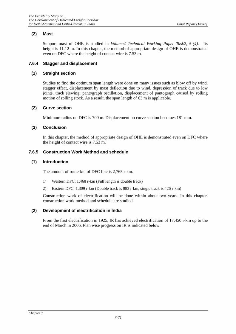
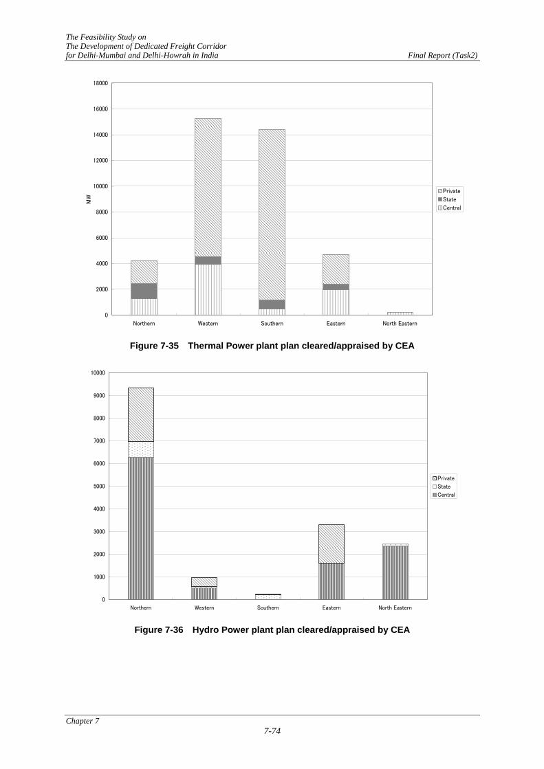
The total power of plants relevant to the Western DFC is 15,245 MW by thermal, 980 MW by hydro as shown in Figure 7-35 and Figure 7-36. There are enough capacities to compare with proposed electrification of Western DFC which requires about 1,000 MW. And discussion with relevant Experts and during meetings with MOR and RITES officers it has been mentioned a number of times that “IR has a priority for supply of electric power”. Then there seems to be no problems in the electrification of the Western DFC with regards to availability of electric power.
Grids relevant to the both corridors are shown in Figure 7-37. Then both the corridors are able to access the grid for their power supply.
Chapter 7 7-73
The Feasibility Study on The Development of Dedicated Freight Corridor for Delhi-Mumbai and Delhi-Howrah in India Final Report (Task2)
0
2000
4000
6000
8000
10000
12000
14000
16000
18000
Northern Western Southern Eastern North Eastern
MW
Private
State
Central
Figure 7-35 Thermal Power plant plan cleared/appraised by CEA
0
1000
2000
3000
4000
5000
6000
7000
8000
9000
10000
Northern Western Southern Eastern North Eastern
Private
State
Central
Figure 7-36 Hydro Power plant plan cleared/appraised by CEA
Chapter 7 7-74

The Feasibility Study on The Development of Dedicated Freight Corridor for Delhi-Mumbai and Delhi-Howrah in India Final Report (Task2)
Source:Power Map of India 2003, Central Board of Irrigation & Power
Figure 7-37 Grid relevant to the both corridors
Estimated power required for DFC
Based on the plan of train operation, estimated energy required for DFC is calculated as follows;
Table 7-26 Plan of transported freight (unit is 109 net tonne km)
Year 2013 2018 2023 2028 2031 Bulk 35.5 62.1 74.9 77.8 79.4 Eastern Cont. 0.4 0.8 1 1.2 1.2
Bulk 13.4 19.8 21.9 24 25.4 Western Cont. 16 48.9 72.4 95.3 109.4
Gross tonne km is calculated as follows;
Bulk: Gross ton km = Net ton km x 1.5
Chapter 7 7-75

The Feasibility Study on The Development of Dedicated Freight Corridor for Delhi-Mumbai and Delhi-Howrah in India Final Report (Task2)
Cont.: Gross ton km = Net ton km x 1.83
Table 7-27 Transported freight (unit is 109 gross tonne km)
Year 2013 2017 2018 2022 2023 2028 2031 Bulk 53.5 62.9 67.0 69.0 112.9 117.5 119.9 Eastern Cont. 0.7 0.8 1.4 1.6 1.9 2.2 2.3 Bulk 20.6 21.5 30.9 33.4 35.6 39.4 41.9 Western Cont. 28.9 34.1 89.3 124.2 132.6 174.4 200.3
As train speed is assumed as 75 km/h, average energy consumption rate is as follows;
Bulk: 6.8 kWh / (1000 gross tonne-km) Cont.:12.1 kWh / (1000 gross tonne-km)
Table 7-28 Energy consumption (unit is 108 kWh)
Year 2013 2017 2018 2022 2023 2028 2031 Eastern 3.7 4.4 4.7 4.9 7.9 8.3 8.4 Western 4.9 5.6 12.9 17.3 18.5 23.8 27.1
Trains are operated for 20 hours per day. Number of trains per hour is assumed to be seven. However maximum number of trains per hour is assumed to be nine. Therefore maximum power demand per hour is calculated as follows;
Table 7-29 Maximum power demand per hour (unit is MW)
Year 2013 2017 2018 2022 2023 2028 2031 Eastern 66 77 83 86 139 145 149 Western 86 99 227 305 325 419 477
Instant maximum electric power demand is assumed 1.5 times of maximum power demand per hour.
Table 7-30 Instant maximum power demand (unit is MW)
Year 2013 2017 2018 2022 2023 2028 2031 Eastern 98 116 125 129 209 218 223 Western 129 148 341 457 488 628 716
Total 228 263 466 586 697 846 938
As mentioned above, CEA (Central Electric Authority) is making plans to develop power plants, total 70,275 MW including thermal and hydro plants in India. The total power of plants relevant to the Western DFC is 15,245 MW by thermal and 980 MW by hydro as shown in Figure 7-35 and Figure 7-36.
Total instant maximum power demand required for DFC in 2031 is planed to be 938 MW that is, small compared to the capacity of power plants planned by CEA.
7.7 TRAIN OPERATION SYSTEM
7.7.1 Total Traffic Control System of DFC
It is recommended to introduce a fully computerised total traffic control system combining the telecommunication system, signalling system, centralised train control centre and train operation management system for the DFC’s optimum traffic control. This system makes a punctual scheduled train operation, slim organisation, and effective and rationalised facilities
Chapter 7 7-76

The Feasibility Study on The Development of Dedicated Freight Corridor for Delhi-Mumbai and Delhi-Howrah in India Final Report (Task2)
management. As a consequence of this, effective, low cost and competitive freight transport for DFC can be achieved.
The system consists of subsystems such as train operation management system, signalling system, automatic train protection system and train-ground telecommunication system. The modernised mobile telecommunication and optical fibre communication system connect the train operation centre, stations, maintenance depots and drivers as shown in Figure 7-38. This system will provide a seamless railway operation.
The total traffic control system envisaged will be one each for both Corridors. However, assuming through train operation for both Corridors, both total traffic control systems should be interconnected in future.
In addition to the above mentioned system, it is recommended to introduce the electric power facilities management system SCADA, monitoring system for signalling facilities, etc.
It is desirable to unify the train operation control centres and facilities control centres for both Corridors at the same place for unified operations.
Chapter 7 7-77

The Feasibility Study on The D
evelopment of D
edicated Freight Corridor
for Delhi-M
umbai and D
elhi-How
rah in India Final Report (Task2)
Mimic Panel
CTC Centre Equipment
CTC Station Equipment
CTC Station Equipment
Electronic Interlocking
Electronic InterlockingAutomatic Block System
Advanced TPWS
Transmission Line (OFC)
Point Machine
Point Machine
Signalling system between stations
Transponder or track circuit
Signalling system
Signalling system
Automatic Route
Control
Diagram Management
System
Diagram Planning System
Console (Video Display & Keyboard)
Traffic Control system In OCC
Mobile Communication
System
Cab Signal System (Option)
Wayside Signal
Train Detector= AF Track Circuit
Figure 7-38 Configuration of Total Traffic C
ontrol System
Chapter 7
7-78

The Feasibility Study on The Development of Dedicated Freight Corridor for Delhi-Mumbai and Ludhiana-Sonnagar in India Final Report (Task2)
7.7.2 Performance and specification requirements for the DFC operation control system
(1) Performance of the operation control system
Computerized operation control systems are very common these days. Train operation schedule data is required for computer-controlled route control. It is also possible to accumulate actual train operation data in the system. This data can be used to build various systems. However, since the freight train operation is not limited to DFC, there is a need to input supplemental information from other sections. Because of this, we recommend the following as the minimum functions for starting operation on the DFC.
1) Computerized route control.
2) Providing dispatchers with predicted train operating schedules.
3) Provide stations, train crew depots and others with train current operation position information.
4) Provide a train radio system that enables the dispatchers to communicate directly with train crews.
(2) Design of train operation control system
It is predicted that there will be a limited amount of traffic passing through both Eastern and West DFC. And the length of both corridors is quite long. Therefore, it would be best if each corridor had its own system. However, if the Operation Control Centre (OCC) was in one location it would facilitate tight collaboration in the control of traffic on both sections.
Indian Railways has a complex network of lines. A decentralized system is desired to fully utilize this network. However, in consideration of its construction cost and the traffic area that should be limited mainly to the DFC at the moment, the centralized system is the most practical. It is desirable that dispatchers for traffic and each engineering section will be gathered together in a room of the OCC. Monitor system for signalling and telecommunication should be gathered together also for the speedy resuming from system failure. If DFC is electrified, SCADA would be provided and it should be controlled in the same room of the OCC.
1) Design of the centralized system
2) Installation of systems for both Eastern and Western DFC in the same room of the OCC.
3) Installation of SCADA system also in the same room of the OCC.
4) Installation of monitoring system also in the same room of the OCC.
7.7.3 Configuration of the Computerized Traffic Operation Control System
Traffic operation control is the system which displays the current position of the train in the OCC, giving its staff the information needed for controlling the signals at each station as shown in Figure 7-39 and Table 7-31.
Chapter 7 7-79

The Feasibility Study on The Development of Dedicated Freight Corridor for Delhi-Mumbai and Ludhiana-Sonnagar in India Final Report (Task2)
R e s u lt o f th e tra in o p e ra tio n
C o n tro l d a ta
T ra in d ia g ra m D B s ys te m C R C S
C T C
S ta tis t ic s ys te m
In te r lo c k in g s ys te m
S ig n a l T u rn o u t
In te r lo c k in g s ys te m
S ig n a l T u rn o u t
In te r lo c k in g s ys te m
S ig n a l T u rn o u t
M o n ito r
M o n ito r
M o n ito r
M o n ito r
Figure 7-39 Configuration of the Computerized Traffic Operation Control System
The system is comprised of the following equipment: equipment that conveys the data between the OCC and each station, a train operation display board that is provided in the OCC, signal control consoles, and information monitors to show the train operation status information that has been acquired by this system at stations and crew depots.
Table 7-31 Train operation system installed in OCC
Equipment Outline of facility Note Time table control system
To control time table in the area based on diagram maintenance information sent from route control system.
Redundancy by double systems
Operational console Train operation control console and manual route control console are installed. Train operation control console is for man-machine interface in principle.
Telecommunication command console is also installed on the operational console.
Monitor of train operation
To indicates images of all lines in big displays and information such as section occupancy, train number, etc. required for train controller.
There are mimic type and projection type, etc. It is defined which display will be adopted by considering recognisability.
Automatic route control system(ARS)
To track trains according to signalling information data sent from every station via CTC, and to control time scheduling at the stations to be controlled. And to process route control based on the above information.
Redundancy by double systems
Time table making system
To make basic diagram, to indicate resulted diagram, to make crews working diagram. To log the results.
Single system
7.7.4 CTC System
The CTC System consists of the central equipment installed at OCC, station equipment installed at every station, transmission lines by optical fibre communication LAN. All equipment is connected by transmission lines. The CTC system transmits the information on train position, route setting, turnout direction, etc. required for train dispatchers to the OCC. The central equipment transmits route control information to each station. The CTC system should be double system as redundancy.
Chapter 7 7-80

The Feasibility Study on The Development of Dedicated Freight Corridor for Delhi-Mumbai and Ludhiana-Sonnagar in India Final Report (Task2)
7.8 TELECOMMUNICATIONS AND SIGNALING SYSTEMS
7.8.1 Telecommunications System
(1) Objective and General Required System Functions
Dedicated Freight Corridor Corporation of India Ltd (DFCCIL) will be established for the purpose of making design, budget arrangement, construction, operation and maintenance arrangements for the DFC project. Most of the rail tracks for the DFC are planned to be developed along existing rail tracks. In addition, some of existing sections include a communications system. However, in order to separate control and management responsibility from existing facilities operated by Indian Railway’s and those that will be operated by the DFC, the JST has proposed that a totally new communication facility be developed for DFC.
The objective of the telecommunications system is to develop a new train communications system to assist with and increase the operational capability and safety of the DFC. In order to realize this objective and maximize the project benefit, the following main components are required:
1) Development of a dedicated fixed communications system, and
2) Development of a dedicated mobile communications system.
Based on the study mentioned in Section 8.9.1 (Proposed system) and the above concept, the JST proposes 4 major systems:
1) Optical Fibre Cable (OFC) communication systems with Synchronous Digital Hierarchy (SDH) technology for dedicated fixed communications and for accessing lines between Base Transceiver Stations (BTS) and Base Station Controllers (BSC) via GSM-R
2) GSM-R for dedicated mobile communications
3) Solid state type digital electronic exchanges for the telephone exchange systems
4) Concentrated dispatching telephone systems with selective calling functions for the dispatching telephone systems
The general system functions required for each system are shown in Table 7-32 below.
Chapter 7 7-81

The Feasibility Study on The Development of Dedicated Freight Corridor for Delhi-Mumbai and Ludhiana-Sonnagar in India Final Report (Task2)
Table 7-32 General Required Function of Each Telecommunications System
Name of System Required Function
1. OFC communications system
Provide voice and data communication circuits between the following sections; - Stations - Centralized Traffic Control Centre (CTCC) and stations - CTCC and trains through GSM-R
2. GSM-R communications system
Provide voice communication circuits between the following sections, with expandability of data transmission: - CTCC and trains - Trains and stations - Wayside and Operation & Maintenance (O&M) centres for
the purpose of O&M work In addition, mobile communications provides all operational areas of trains, including wayside, yards, stations, etc., with coverage of the mobile service. However, from an operational point of view, communication sections needs to be carefully considered to determine how efficient train operations can be attained in order to avoid an increase in unnecessary communications demand.
3. Solid state type digital electronic exchange with ISDN functions
Exchange calls between subscribers. For this purpose digital electronic exchanges are planned to be installed at the following locations: - CTCC and stations - Terminal station, Junction station, Crossing station - Other related offices (if any).
4. Concentrated dispatching telephone system
- Provide voice communication for dispatching work without using exchanges. The system will be used by the following 5 controller staff: 1)Traffic Controller, 2)Electric Power Controller, 3)Signal Controller, 4)Telecommunications Controller and 5)Facility Controller
(2) Design Conditions and System Outline
1) Basic Condition
The design of telecommunications system basically depends on the numbers of stations and section length. The following Table 7-33 shows the basic conditions of alignment for both Western and Eastern DFC in the PETS-II.
Table 7-33 Basic Conditions
Item Western DFC Dadri-JNPT
Pirthala-TKD
Eastern DFC Sonnagar-Dadri
Khurja-Dhandrikalan Crossing station 32 stations 52 stations Junction station 10 stations 12 stations Terminal station 3 stations 3 stations Total length 1,515km 1,284km
2) Design Condition and System Outline
The design conditions and system outline for a preliminary design are defined in the following section as shown in Table 7-34. In particular, for the design of the GSM-R system using radio, the Base Transceiver Station (BTS) interval is determined from the
Chapter 7 7-82

The Feasibility Study on The Development of Dedicated Freight Corridor for Delhi-Mumbai and Ludhiana-Sonnagar in India Final Report (Task2)
general characteristics of the radio equipment. However, the radio system propagation distance depends on geographical and atmospheric conditions, as well as features such as noise from other radio emissions. Therefore, the preliminary design system will need to undergo radio wave propagation testing in the detailed design stage. The major purposes of wave propagation test are as follows;
a) To identify the interval and location of Based Transceiver Station
b) To specify the required specification of radio equipments
c) To prepare frequency allocation plan including required number of frequencies
Chapter 7 7-83

The Feasibility Study on The Development of Dedicated Freight Corridor for Delhi-Mumbai and Ludhiana-Sonnagar in India Final Report (Task2)
Table 7-34 Design Conditions and System Outline
Item Design Conditions & Outline
1. Optical Fibre Cable (OFC) communications system
1) System configuration
Two SDH systems: • STM-1 for the GSM-R BTS • STM-4 for back up of GSM-R, other
telecommunication services • Unit redundant configuration (Hot
standby)
2) Network configuration
Loop system (2 cables): In order to make the loop configuration, a total of 2 cables are to be installed in pipes alongside tracks, one for one side of the track and one for the opposite side of the track.
3) Number of cable cores and allocation of OFC cores
• Number of cores for one cable: 24 cores • Allocation of cores: STM-1: 2 cores STM-4: 2 cores
In addition, the following number of OFC cores will be used for signalling purposes:
Block system: 2 cores CTCC: 2 cores ATSP: 2 cores
4) Maximum distance between equipment Approximately 80km 5 )Interface E1, 2W/4W E&M, 10/100BaseT, others 6) Charger and battery for the SDH or MUX equipment at
waysides Should be equipped
2. GSM-R 1) Distance between BTS’s Within 7km
2) Function of system Point to point calls, Broadcast voice calls, Group voice calls, Multiparty voice calls,
Emergency voice calls, etc. 3) Charger and Battery for the BTS equipment at waysides Should be equipped 4) Interface E1 and others 5) UPS for MSC equipment Should be equipped
3. Electronic Digital Exchange
1) Capacity of exchange
There types of exchange: 5,000 lines: Terminal station 1,000 lines: Junction station 256 lines: Crossing station
2) Interface for trunk line E1, 2W, 4W and others 3) Charger & Battery Should be equipped
4. Dispatching telephone
1) Type of system Concentrated telephone system with selective calling function
2) Function of system
• Individual calls • Group calls (Group is preset by the
controller) • Broadcast calls • Hands free communication function via
speakers and microphones 3) Interface 2W/4W E&M
Chapter 7 7-84

The FeasibThfor Delhi-Mumb
Chapter 7
ility Study on e Development of Dedicated Freight Corridor
ai and Ludhiana-Sonnagar in India Final Report (Task2)
7-85
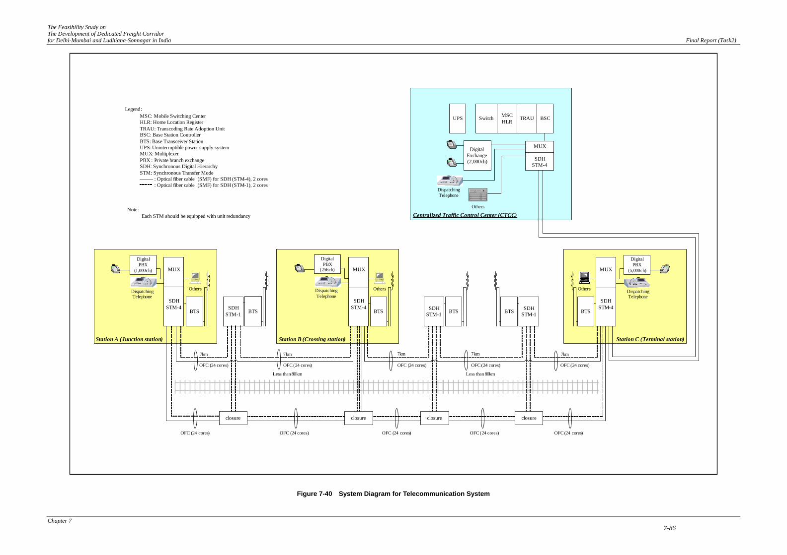
3) System Configuration
Based on the required functions listed above, the system configuration is illustrated in Figure 7-40 below. The major components of each sub-system are listed in Table 7-35 below.
The Feasibility Study on The Development of Dedicated Freight Corridor for Delhi-Mumbai and Ludhiana-Sonnagar in India Final Report (Task2)
Chapter 7 7-86
BTSSDHSTM-1 BTS SDH
STM-1 BTS
7km 7km 7km
OFC (24 cores)
Less than 80km
BSCTRAUMSCHLR
Switch
DigitalExchange(2,000ch)
UPS
BTS
MUX
SDHSTM-4
Digital PBX
(256ch)
Dispatching Telephone
DigitalPBX
(5,000ch)
Dispatching Telephone
Dispatching Telephone
Station B (Crossing station) Station C (Terminal station)
Centralized Traffic Control Center (CTCC)
OFC (24 cores)
BTS
DigitalPBX
(1,000ch)
Dispatching Telephone
Station A (Junction station)
BTSSDH
STM-1
MUX
SDHSTM-4
Less than 80km
OFC (24 cores)OFC (24 cores)OFC (24 cores)OFC (24 cores)
OFC (24 cores)OFC (24 cores)
Legend:MSC: Mobile Switching CenterHLR: Home Location RegisterTRAU: Transcoding Rate Adoption UnitBSC: Base Station ControllerBTS: Base Transceiver StationUPS: Uninterruptible power supply systemMUX: MultiplexerPBX : Private branch exchangeSDH: Synchronous Digital HierarchySTM: Synchronous Transfer Mode : Optical fiber cable (SMF) for SDH (STM-4), 2 cores : Optical fiber cable (SMF) for SDH (STM-1), 2 cores
Others Others Others
Others
MUX
SDHSTM-4
MUX
SDHSTM-4
closureclosureclosureclosure
7km7km
OFC (24 cores)OFC (24 cores)
Note: Each STM should be equipped with unit redundancy
Figure 7-40 System Diagram for Telecommunication System

The Feasibility Study on The Development of Dedicated Freight Corridor for Delhi-Mumbai and Ludhiana-Sonnagar in India Final Report (Task2)
Table 7-35 Major Components of Each Telecommunications Sub-System
Item Wayside Station CTCC
1. Optical Fibre Cable (OFC) Communications System
1) SDH terminal equipment o o o 2) Multiplexer (MUX) o o o 3) Charger and Battery o o o 4) Miscellaneous equipment o o o
2. GSM-R
1) Base Transceiver Station (BTS) with Charger and Battery o o
2) Base Station Controller (BSC) o 3) Transcoding Rate Adoption Unit (TRAU) o 4) Mobile Switching Centre (MSC/VLR) o
5) Home Location Register/Authentication Centre (HLR/AC) o
6) UPS for MSC related equipment o 7) Miscellaneous equipment o o o
3. Electronic Exchange 1) Electronic Exchange with Battery and Charger o o
2) Main Distribution Frame (MDF) or Intermediate Distribution Frame (IDF) o o
3) Miscellaneous equipment o o 4. Concentrated Dispatching Telephone System
1) Master controller and operation console o 2) Slave telephone terminal o 3) Miscellaneous equipment o o
CTCC: Centralized Traffic Control Centre
4) Harmonization with stage wised development
CTCC will be planned to be constructed in Delhi area. The master telecommunication facilities including optical fibre cable system, GSM-R system, dispatching telephone system will also be installed in CTCC. In order to meet stage-wised development plan, these master facilities and optical fibre cable link between CTCC and first stage area should be installed in the first stage of the Project.
7.8.2 Signalling System
(1) Signalling System for DFC
According to the optimum technical option stated in the chapter 8 of separate volume (Task 0&1), following signalling systems as shown in Table 7-36 will be provided at the station area and between stations.
Chapter 7 7-87

The Feasibility Study on The Development of Dedicated Freight Corridor for Delhi-Mumbai and Ludhiana-Sonnagar in India Final Report (Task2)
The JICA Study Team recommended to adopt block section length as 1.5km for between stations, 1.0km for nearly stations. Detailed study is shown in Volume 4 Technical Working Paper Task2, 7-(14)
Table 7-36 Signalling system list provided in DFC
System or Equipment Name
The installed location
Outline of function Note
Electronic Interlocking System Or SSI (Solid State Interlocking)
At each station area Route setting with the interlocking between signals, and between signals and point machines.
Interface to CTC and Automatic Block System
Automatic Block System Between stations Provide 1.5 km block section between stations and interval control between trains
Interface to SSI and Advanced TPWS
CTC (Centralised Train Control System) Station Equipment
At each station
Transmit the route setting information from OCC to SSI, and the information for train dispatcher from SSI to OCC.
Interface to SSI and CTC Centre equipment via Optical Fibre Cable.
Advanced TPWS or Automatic Train Protection System
At each station and between stations
Transmit and Receive the information between ground and train with track circuit or transponder. Protect the train against head-on-collision, rear end collision or entering wrong line. 【Option】Indicate the distance of the advanced signal and its aspect in the cab. This option will be available in fog.
Transponder is installed between rails. Equip on-board device for advanced TPWS And Cab signal (option)
Between stations Train is detected with AF track circuit.
Joint less (Non insulated)
Train Detection System
At each station area Train is detected with AF track circuit.
Insulated Rail Joint
Electric Point Machine At each station Automatically control turnouts by the command from SSI
Interface to SSI
Signal (Entrance, Departure Shunting and Block)
At each station and between stations
Be controlled with SSI and ABS. Home and starting signal are colour light. Shunting signal is position light signal.
Interface to SSI and Automatic Block System
Note) The progress of train detection system is stated in Volume4 Technical Working Paper Task2, 7-(6). The content of Advanced TPWS is stated in Volume4 Technical Working Paper Task2, 7-(7)..
(2) Construction Method
Regard with the construction of such modernized signalling system it will be matter to find and to train experienced signalling engineers. The details mention in Volume 4 Technical Working Paper Task2, 7-(13)
7.8.3 Power Supply for Telecommunication and Signalling
The AC power for Telecommunication and Signalling will be supplied with the step-down Auxiliary Transformer (AT) and back up with the 2 systems of Extra High Voltage 25kV and commercial Power (Total 3 system power). Moreover in Junction and Terminal stations Diesel engine generator will be provided as back up.
Chapter 7 7-88

The Feasibility Study on The Development of Dedicated Freight Corridor for Delhi-Mumbai and Ludhiana-Sonnagar in India Final Report (Task2)
Power Supply for Telecommunication and Signalling will consist of Insulated Transformers, Step down transformers, UPS’s (Uninterrupted Power Supply), Rectifiers and power distribution boards.
Besides this, power supply will be backed up with Batteries for protection against instantaneous power failure.
(1) Power supply equipment in station area
Power supply to main equipments for signalling and telecommunication is shown in Table 7-37. The Rectifiers and UPS’s are duplicated system.
Table 7-37 Power supply for signalling and telecommunication systems
Load equipment Type of Power
Protect against wink power failure Note
Electric point machine AC Non Colour Light Signal AC Non Track Circuit DC Rectifier+Batteries AF track circuit Signalling system DC Rectifier+Batteries Logic units for SSI, CTC VDT AC UPS Video Display Terminal in
station control room Telecommunication system DC Rectifier+Batteries
(2) Power supply equipment between stations
AC power supply cable will be installed between stations from the power supply equipment that has back up with 2 systems of High voltage and commercial power in the station equipment room. The compensated power will be supplied from this power cable to the power box which is installed at the block section boundary and radio base.
Rectifiers and batteries will be mounted in the power box for protection against wink power failure and this power will be supplied to equipments such as Audio Frequency (AF) track circuit box, Absolute Block System control box, Synchronous Digital Hierarchy (SDH), Base Transceiver Station (BTS) and so on.
7.9 ROLLING STOCK
7.9.1 Performance and structure of locomotives
(1) Electric locomotives for the DFC
This investigation into the performance and design of locomotives is based on a bulk freight train hauling 5,800 t, DSC on flat wagon of 4,500 t and DSC on well wagon of 3,500 t trains hauling.
Detailed study is described in Volume4 Technical Working Paper Task2, 7-(8).
The choice of a locomotive with a 22.5 tonne axle weight would enable operation on feeder lines. The propulsion and traction system should be capable of providing an adhesion coefficient of 0.38 or more at the starting.
If electric traction is adopted, it would be favourable to use an 8-axle locomotive for bulk train hauling and a 6-axle locomotive for container train hauling.
Chapter 7 7-89

The Feasibility Study on The Development of Dedicated Freight Corridor for Delhi-Mumbai and Ludhiana-Sonnagar in India Final Report (Task2)
Assuming running conditions such as maximum speed 100 km/h on level line, balancing speed 65-80 km/h on up gradient section. The necessary power of locomotives are 7,200 Hp for 3,500 t container train, 9,000 Hp for 4,500 t container train and 12,000 Hp for bulk train hauling. Two types of locomotive are recommended such as 6-axle 9,000 Hp and 8-axle 12,000 Hp. Either type should provide 1,500 Hp per axle.
There are examples of electric locomotives having power more than 2,000 Hp per axle in Europe. However, de-rating should be needed by considering the differences of climate conditions between India and Europe, especially high temperature. Therefore, the JST recommends 1,500 Hp per axle.
If diesel traction is used, it would require three 6-axle locomotives for bulk trains and two 6-axle locomotives for container trains to match the average speed of the electric locomotives. It should be noted that even if 6-axle, 5,000 Hp locomotives were used, the power available at the wheel would be 750 Hp.
On the other hand, it is possible for two locomotives for bulk and one locomotive for container train, by modifying the condition, to reduce average speed in diesel traction. The results of calculation on trip time and average speed are shown in the Table 7-38 and Table 7-39 show the results of calculations based on the following scenarios: a 30 km level track between two stations; and modelled inbound (up) and outbound (down) lines that have a 10 km level section, a 10 km section with a 1/200 gradient and then another 10 km level section.
Since the detailed line alignment is not yet fixed, the calculations are based on the assumption that the 1,500 km length between Mumbai and Delhi has about 60 km of 1/200 gradient. The ratio for the number of diesel locomotive to electric locomotives is estimated from a weighted average of the trip times for each case.
The results are obtained for 6 axle electric loco as 1.00 versus 6-axle diesel loco as 1.17 for container trains, 8-axle electric loco as 1.00 vs. 6-axle diesel loco as 1.90. These digits are used in the economic analysis in Section 5.3.
Chapter 7 7-90

The Feasibility Study on The Development of Dedicated Freight Corridor for Delhi-Mumbai and Ludhiana-Sonnagar in India Final Report (Task2)
Table 7-38 Simulation of Container Train, 4,500 t
EL (One) DL (One) Ratio DL/EL Time (min) 28.5 33.4 1.172
Level line Average Speed (km/h) 63.2 54.0 0.854Time (min) 31.8 39.9 1.255
Model line up Average Speed (km/h) 56.7 45.1 0.795Time (min) 28.7 32.1 1.118Model line
down Average Speed (km/h) 62.7 56.1 0.895
Note: Nos. of Diesel loco and Electric loco is equal for hauling a container train. In this case, loco powers are assumed as 5,000 Hp for Diesel, 9,000 Hp for Electric.
Table 7-39 Simulation of Bulk Train, 5,800 t
EL (One) DL (Two) Ratio DL(Two)/EL(One)
Time (min) 28.9 27.3 0.945 Level line
Average Speed (km/h) 62.4 66 1.058 Time (min) 31.1 31.6 1.016 Model line
up Average Speed (km/h) 57.9 56.9 0.983 Time (min) 31.7 30.3 0.956 Model line
down Average Speed (km/h) 56.8 59.4 1.046 Note: A container train is hauled by two Diesel locos or one Electric loco. In this case, loco powers are assumed as 5,000 Hp for Diesel, 12,000 Hp for Electric.
(2) Development and building locomotives
The JST recommends electric locomotives with 25 t axle weight, 6-axles 9,000 Hp for hauling DSC on well train and 8-axles 12,000 Hp for bulk freight train on the DFC lines. The latest electric locomotive WAG-9 is 6-axle and 6,000 hp. Hence, the development of new locomotives with high power should start.
The prices of new locomotives are estimated as USD 4.9 million for 12,000Hp based on the price of WAG-9 considering with power up and development costs.
It requires about 5 years from the time of commencement of development to the start series production including building prototypes, its commissioning schedule is as shown in Figure 7-41. Therefore, new development should start at the same time as the commencement of the project construction considering total project completion period. And prototypes should be built at least two years before the opening for confirmation of its performances and interferences between signalling and telecommunication systems. It is desirable to start the series production after these confirmations.
Chapter 7 7-91

The Feasibility Study on The Development of Dedicated Freight Corridor for Delhi-Mumbai and Ludhiana-Sonnagar in India Final Report (Task2)
1st Year 2nd Year 3rd Year 4th Year 5th Year 6th Year
L/A ▼
Specification(Approval of RDSO)
Selection of General
Tender Document
Tender
Design of Prototype(Approval of RDSO)
Test and Evaluation
Design of Series Production
Preparation of Series
Delivery of RS
Manufacturing of Prototype
Manufacturing of Pre-SeriesProduction
Figure 7-41 Schedule of electric locomotive development
And it is desirable to start preparation works including training for drivers and maintenance staffs, confirmation of operating timetable, etc. at least one year earlier.
Assuming same time for opening of the both Corridors, numbers of locomotive are estimated as shown in Table 7-40. It will be necessary 168 electric locomotives for both Corridors at the opening, assuming that the Western DFC is electrified.
It should be noted that numbers. of locomotive for feeder lines are excluded. The necessary numbers of locomotive for further lines should be fixed by the train operation plan done by IR
It seems it will require longer time for development of such modernised high performance electric locomotives by CLW or BHEL only. And building 168 locomotives in a short period will exceed their capacities too. The maximum capacity of CLW is estimated as 200 per year, that of BHEL as 50. Therefore, it is recommended to develop new locomotives by foreign loco builders and to take adequate measures for increasing building capacity including new factory construction or importing the locomotives. A plan of building locomotives is also shown in Table 7-40
Chapter 7 7-92

The Feasibility Study on The Development of Dedicated Freight Corridor for Delhi-Mumbai and Ludhiana-Sonnagar in India Final Report (Task2)
Table 7-40 Necessary nos. and building nos. of electric locomotives estimation Type 2011 2012 2013 2014 2015 2016 2017 2018 2019 2020 2021 2022 2023 2024 2025 2026 2027 20286 axles 2 3 3 4 4 4 5 5 5 5 5 5 5 5 5 58 axles 80 96 111 126 141 156 158 160 162 164 165 167 169 170 171 173Subtotal 82 99 114 130 145 160 163 165 167 169 170 172 174 175 176 1786 axles 49 66 83 100 117 134 148 162 175 189 202 216 229 233 233 2338 axles 37 41 45 48 52 55 56 57 58 59 59 60 61 62 63 64小計 86 107 128 148 169 189 204 219 233 248 261 276 290 295 296 297
168 206 242 278 314 349 367 384 400 417 431 448 464 470 472 4756 axles 10 30 11 18 17 18 17 17 15 14 13 14 13 14 13 4 0 08 axles 10 30 77 20 19 18 19 18 3 3 3 3 1 3 3 2 2 3Total nos. 20 60 88 38 36 36 36 35 18 17 16 17 14 17 16 6 2 3Sum up 20 80 168 206 242 278 314 349 367 384 400 417 431 448 464 470 472 475
TheEasternCorridor
TheWesternCorridor
Total necessary nos.
Buildingloco nos.
7.9.2 Freight wagons
With regard to freight wagons, it is the need of the hour to develop new wagons corresponding 25 t axle load based on BLC, BOXN, etc. It is possible to increase axle load within the present loading gauge except with DSC wagons. Then, the transport planning is studied by keeping the present wagon length. Proposals on wagon structure are shown below.
(1) Container wagon
There are two options such as DSC on flat wagon and DSC on well-type wagon for container transport. Subject which will be adopted depends on the result discussed in Section 5.2.
It is recommended to develop flat type DSC wagons adopting 25 t axle load based on the present BLC wagons for the first option.
With regards to the second option, well type wagon, PETS-II did not show the design. However, there are these examples in US and China as shown in Photo 7-1 and Table 7-41, it is possible to develop such wagon for IR’s broad gauge based on the examples.
However, it should be considered for new DSC wagon design there are already some US patents relevant the DSC on well type wagon such as “Railroad container transporting car of increased weight carrying capacity US Patent 4.841.876 publication date 27/06/89”, “Double-stacked freight car, US Patent 4.784.548 publication date 15/11/88”, “Railroad car with double stack container restraint system, US Patent 4.759.294 publication date 17/07/87”, etc.
With regard to comparisons of well-type wagon against flat-type wagon, the well-type wagon lowers the centre of gravity and can run relatively at higher speed than the DSC on flat-type wagon.
The bogies of container wagon should have characteristics with higher stiffness against rolling movement corresponding to higher gravity centre.
Chapter 7 7-93

The Feasibility Study on The Development of Dedicated Freight Corridor for Delhi-Mumbai and Ludhiana-Sonnagar in India Final Report (Task2)
Photo 7-1 Well typed DSC wagon of Chinese Railways
Table 7-41 Specification of well typed DSC wagon in China
Gauge 1,435 mm Tare Weight 21.8 t Loading Weight 78 t, 5.15 t/m Maximum Speed 120 km/h Minimum Radius 145 m Body Length/Width 18,500 mm/2,912 mm Length between coupler centres 19,466 mm Maximum Height 290+2,438+30+2,591=5,349 mm
290+2,591+30+2,896=5,807 mm
(2) Bulk wagons
In order to maximize payload within the limited loop length, we studied a design based on the BOXN type 2-axle bogie wagons used for coal transport. This design enables an increased car height within the allowances for the current loading gauge while maintaining a 10.6 m car length including couplers.
Photo 7-2 BOXN Type wagon
Chapter 7 7-94

The Feasibility Study on The Development of Dedicated Freight Corridor for Delhi-Mumbai and Ludhiana-Sonnagar in India Final Report (Task2)
Table 7-42 BOXN/BOXNHS (Open-top Wagon) Technical Specifications
Description of Wagon BOXN/BOXNHS (Open-top wagon)
Track Gauge 1,676mm
Length (H.S.-H.S.) 9,784mm
Height (From – R.L.) 3,225mm
Width 3,200mm
Bogie Centre 6,524mm
Tare Weight 22.47t
Carrying Capacity 58.81t
Coupler Type CBC
Bogie Type Casnub22NLB / Casnub22-HS Bogie
Brake System Air Brake
Used For Carrying Coal, Stone, Steel, etc.
An image of the BOXN design is shown in Photo 7-2 and the main specifications are provided in Table 7-42. Its height from rail level is 3,225 mm with margins to the loading gauge. As shown in Figure 7-42, a 500 mm increase in height would increase payload by 30% at an axle load of 30 t. It goes without saying that the bogies and car body would have to be redesigned.
It is desirable to introduce stainless steel body design for reducing corrosion caused by sulphur contained in coals and iron ores. The stainless steel wagons were developed about 5 years ago and not introduced widely in India because of relatively high material costs. IRSM44 equivalent to SUS 410 in JIS are used for the wagons. However, durability of IRSM44 is less than SUS 304, etc. containing Nickel. The stainless steel BOXN wagons are built to almost the same design as those of the present steel wagons.
Chapter 7 7-95

The Feasibility Study on The Development of Dedicated Freight Corridor for Delhi-Mumbai and Ludhiana-Sonnagar in India Final Report (Task2)
Figure 7-42 Proposed structure and loading gauge
(3) Wagon for automobile transport
The large loading gauge for DSC on the DFC lines will enable the development of three-level wagons as shown in Figure 7-43, for automobile transport to serve the growing automobile production in India. Detailed design should be done based on actual demand.
Chapter 7 7-96

The Feasibility Study on The Development of Dedicated Freight Corridor for Delhi-Mumbai and Ludhiana-Sonnagar in India Final Report (Task2)
Figure 7-43 Image of auto carrier
(4) Development and building wagons
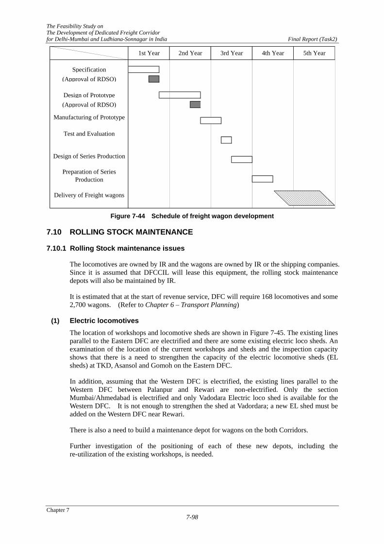
The DFC requires 2,700 wagons at the opening based on the present demand forecasting. It requires about four years for the period from starting development to starting series production as shown in Figure 7-44. Therefore, it is recommended that the development of wagons should be started five years before the opening. If the development is delayed, DFC lines will be opened by using the existing stocks.
The prices of wagons are estimated as USD 50,000 bulk wagons, USD 65,000 well type container wagon based on actual prices of IR and Chinese Railways.
It is considered that wagons are procured and owned by forwarders as like as CONCOR who owns container wagons. These wagons should be designed to adapt to the needs of the forwarders.
Chapter 7 7-97
The Feasibility Study on The Development of Dedicated Freight Corridor for Delhi-Mumbai and Ludhiana-Sonnagar in India Final Report (Task2)
Specification(Approval of RDSO)
Design of Prototype(Approval of RDSO)
Test and Evaluation
Delivery of Freight wagons
1st Year
Preparation of SeriesProduction
Design of Series Production
Manufacturing of Prototype
5th Year4th Year3rd Year2nd Year
Figure 7-44 Schedule of freight wagon development
7.10 ROLLING STOCK MAINTENANCE
7.10.1 Rolling Stock maintenance issues
The locomotives are owned by IR and the wagons are owned by IR or the shipping companies. Since it is assumed that DFCCIL will lease this equipment, the rolling stock maintenance depots will also be maintained by IR.
It is estimated that at the start of revenue service, DFC will require 168 locomotives and some 2,700 wagons. (Refer to Chapter 6 – Transport Planning)
(1) Electric locomotives The location of workshops and locomotive sheds are shown in Figure 7-45. The existing lines parallel to the Eastern DFC are electrified and there are some existing electric loco sheds. An examination of the location of the current workshops and sheds and the inspection capacity shows that there is a need to strengthen the capacity of the electric locomotive sheds (EL sheds) at TKD, Asansol and Gomoh on the Eastern DFC.
In addition, assuming that the Western DFC is electrified, the existing lines parallel to the Western DFC between Palanpur and Rewari are non-electrified. Only the section Mumbai/Ahmedabad is electrified and only Vadodara Electric loco shed is available for the Western DFC. It is not enough to strengthen the shed at Vadordara; a new EL shed must be added on the Western DFC near Rewari.
There is also a need to build a maintenance depot for wagons on the both Corridors.
Further investigation of the positioning of each of these new depots, including the re-utilization of the existing workshops, is needed.
Chapter 7 7-98

The Feasibility Study on The Development of Dedicated Freight Corridor for Delhi-Mumbai and Ludhiana-Sonnagar in India Final Report (Task2)
MUMBAI
DELHI
KOLKATAVadodara E. Loco Shed
Dahod Workshop
Ghaziabad E. Loco Shed
Asansol E. Loco Shed
Mughalsarai E. Loco Shed
Gomoh E. Loco Shed
Kanpur Central E. Loco Shed
Tughlakabad E. Loco Shed
Ludhiana Loco Shed
Vatva D. Loco Shed
Kanchrapara Workshop
Valsad E. Loco Shed
Figure 7-45 Location of Workshops and Sheds
(2) Freight wagons IR has approximately 214,000 wagons, including the privately owned ones.
The maintenance of these wagons is performed as follows. Periodic overhaul (POH) is performed every 4-1/2 years at a workshop. Routine overhauls (ROH) are performed every 18 months at care centres.
Within the entire IR system, there are 35 workshops for servicing wagons and 57 care centres. Additionally, there are numerous locations adjacent yards or stations that are used for yard examinations.
There is also a need to build a new maintenance depot for wagons on the both Corridors.
Further investigation of the positioning of each of these new maintenance depots, including the reutilization of the existing workshops, is needed.
7.10.2 Improving the quality of the wagons
Based on the present transport conditions, it became clear that wagons failures were affecting the traffic capacity. We therefore compiled and analyzed data about the wagons, mainly in the area of failures, and conducted an investigation into the current maintenance operations.
Chapter 7 7-99

The Feasibility Study on The Development of Dedicated Freight Corridor for Delhi-Mumbai and Ludhiana-Sonnagar in India Final Report (Task2)
(1) Compilation and analysis of data about wagon failures
Whenever there is a wagon failure, an investigative meeting is held at the related workshop to discuss the causes of the failure and the necessary countermeasures. In addition, the results of the failure analysis and the number of occurrences are compiled by the care centres.
This investigation was conducted about the condition of wagon failures on the Northern Railway based on such materials from the Tuglakabad Care Centre. The compiled data is shown in Table 7-43 for BLC wagons and Table 7-44 for air brake wagons. The compiled data is for the period from January to June 2006.
Table 7-43 BLC Type Wagon Failures Month &
yearW/Change ATL DV SAB Side Bearer
Spg.Pivot top EM Pad Adopter Truss bar Other
6-Jan 35 4 0 0 6 0 10 0 0 36-Feb 42 33 0 1 40 4 2 2 0 196-Mar 19 40 1 1 9 4 1 8 2 76-Apr 40 4 0 0 0 2 0 0 4 136-May 25 5 1 1 7 6 2 0 2 266-Jun 0 13 1 2 0 1 0 1 0 27Total 161 99 3 5 62 17 15 11 8 95Avg. 26.8 16.5 0.5 0.8 10.3 2.8 2.5 1.8 1.3 15.8 (Abbreviations) Wheel Change: Changing wheels and axles ATL: Automatic Twist Lock * DV: Control valve *SAB: Automatic Space Adjustor Side Bearer Spg: Truck spring Pivot Top: Body centre pin liner EM Pad: Rubber pad stored on the saddle for shock absorption Adopter: Saddle at the upper part of the roller bearing. Truss bar: Brake beam
Table 7-44 Air Braked Wagon Failures
Month & W/Change DV Adopter EM Pad RA Lock CC Pad SB Sprg. Trolley CBC Pivot Truss Bar BV/Gear OthersOuter Inner Snuber
6-Jan 49 2 0 3 12 6 1 32 15 0 0 1 2 6 22 236-Feb 41 3 0 11 5 3 0 29 11 0 0 0 2 3 7 296-Mar 32 2 2 10 2 2 0 25 9 0 0 0 1 2 20 276-Apr 110 6 0 21 21 15 8 35 22 0 0 0 2 8 23 316-May 61 2 1 11 12 3 0 93 11 0 0 0 1 9 43 326-Jun 59 4 1 4 8 4 1 61 58 2 1 1 0 7 54 92Total 352 19 4 60 60 33 10 275 126 2 1 2 8 35 169 234Avg. 58.7 3.2 0.7 10.0 10.0 5.5 1.7 45.8 21.0 0.3 0.2 0.3 1.3 5.8 28.2 39.0
Helical Spring
The above shows that there have been failures with nearly all wagon equipment. From this information we could assume that there are problems with the thoroughness of the basic maintenance operations.
With regards to air brake systems, it is also possible to consider that the control valve system also has problems. The majority of the failures are rubber parts, such as pads or supply valves. The following two items summarize the nature of the above problems. And we believe that it is imperative that plans be made to correct these problems as quickly as possible.
- There are deficiencies in the performance of basic operations, such as the observance of replacement intervals and/or the incorrect assembly of the equipment or components.
- There are broken or worn pads and defective contact surfaces on the control valve rubber, suggesting that the material is defective.
Chapter 7 7-100

The Feasibility Study on The Development of Dedicated Freight Corridor for Delhi-Mumbai and Ludhiana-Sonnagar in India Final Report (Task2)
These could be one of the causes of the axle box overheating. It is very important that the technicians taking care of the roller bearings are capable of making decisions based on visual examinations and that they know how to take the proper countermeasures against dust in the workplace and properly measure the amount of grease when lubricating.
There are problems caused by components, other than the brake rod, falling onto the under floor equipment. This indicates a need for solid welding techniques. In particular, there is a significant disparity in the skill levels for electric welding.
(2) Investigation of the condition of maintenance operations
An investigation was conducted at three locations: the Jaghadari workshop and the Tuglakabad and Vishakhapatnam care centres.
These Tuglakabad care centres are all ISO 9001 and are fully controlled. They are even capable of doing non-destructive testing of crucial components. However, we did find several areas of operation that could be improved.
(3) Suggestions for improving quality
An investigation of the failure data and the actual operating conditions shows that the following would be desirable for improving the transport quality (preventing failures and providing stable transport) of the DFC.
1) Air brakes
a) Improving operations
If the pad is improperly assembled, it will deform and this will result in operational problems. Therefore it is imperative that the technicians fully understand the fundamentals of the assembly operation and then properly implement them.
b) Improving materials
An investigation of the rubber parts, such as the pad for the control valve, and the actual conditions under which they are replaced should be conducted for all worksites in order to understand the level of sealing at the seat of the supply valve and the durability of the pad.
c) Improving the system for changing braking force
On braking force adjusting system according to loaded or unloaded conditions, IR’s wagon adopts manual setting system which changes stroke of brake cylinder. It cannot obtain enough compensation to braking efforts at loading condition and causes miss settings. It is desirable to introduce automatic adjusting system which changes air pressure of brake cylinder according loaded or unloaded.
2) Trucks and axle bearings
a) Axle bearing overheating detection device
Discovering axle bearing overheating before there is damage to the roller bearings makes it possible to prevent major derailments. It would be very meaningful to perform research into improving the inspection skills for roller bearings in conjunction with this device.
b) Flat wheel detection device
If a flat wheel is detected and treated while the flat is still small, it will reduce the
Chapter 7 7-101

The Feasibility Study on The Development of Dedicated Freight Corridor for Delhi-Mumbai and Ludhiana-Sonnagar in India Final Report (Task2)
effect it has on the rail. In addition, early detection will prevent abnormal vibrations from being transferred to the entire running system and this will help to prevent brake and other components from vibrating loose and falling off. Improvements in this area should take into consideration the system for treating the flat after detection and the wheel truing plan.
c) Proper amount of grease for axle bearings
It is very important that the amount of grease used for lubrication is accurately measured. Many times overheating can be traced back to insufficient greasing. There is a need to re-evaluate the greasing procedure.
d) Improving the environment of the axle bearing work area
The area where the bearing components are measured and assembled should be a dedicated space, set apart from the other work areas as a countermeasure to dust. Of course, any planning of the work area environment would take into consideration the positioning of the air compressors and other such equipment.
e) Device for detecting when brake rods have fallen off
There are many steps that can be taken to prevent brake rods from falling off. For example, steps can be taken so that the brake rod will not fall off even if the cotter key or split pin breaks. Proper continuation of these steps can help to prevent major accidents.
When an under floor component falls off, it can usually be traced back to looseness between the pin or cotter key and the hole it is in. This causes the cotter key to break and fall out, which then results in the under floor components falling off.
Therefore, when a freight car enters the POH, all such pins (100%) should be replaced. During the replacement, the holes for these pins should be inspected for signs of wear.
If there is wear, it should be repaired immediately. This will prevent the pins from becoming loose. Wear to a pin hole can be repaired by filling in the hole and re-boring the hole on a drill press.
Not re-using cotter keys or pins and not annealing them, are also very important points.
Therefore, it is important to pro-actively promote the implementation of these basic operations and to continue to keep the inspection equipment in mind as an issue for future inspections.
3) Car body-Improving electric welding skill
We examined some of the filler welds, the welding on tracks and in the steel working operations on the rail car bodies and found that some of the welds had insufficient penetration. There is a need to ensure that there are skilled welders in the work areas. This can be nurtured by a progressive training and certification process.
4) General operations
a) Organization and neatness
Keeping the worksite neat and orderly will improve operating efficiency and help to prevent accidents. There should be designated places for defective parts and
Chapter 7 7-102

The Feasibility Study on The Development of Dedicated Freight Corridor for Delhi-Mumbai and Ludhiana-Sonnagar in India Final Report (Task2)
materials and these should be disposed of on a regular basis. Moreover, tools should always be returned to their designated storage area after the technicians have finished using them. Simply enforcing this procedure will improve the efficiency of the work area. At present, there are significant differences among the work areas.
b) Safety equipment
Protecting the safety of the people in the work areas is always top priority. Therefore there is need to provide all workers with the proper safety equipment and relentlessly promoting safe work practices. It is important that the respective companies protect their human resources from harm so that they can utilize their skills and thereby support themselves and their families.
7.11 ROLLING STOCK DEPOTS
7.11.1 Review of the PETS-II
PETS-II proposed a new Diesel Loco Shed and a new Wagon Maintenance Depot on the Western DFC and included its estimate in the cost. However, no detailed plan and no cost break down were shown in the Report.
(1) Western DFC
Cost of depots is estimated as Rs.155.2 Cr. in PETS-II. Also depots are proposed as diesel loco sheds at Dadri and Marwar, container wagon maintenance depots at Dadri.
Fuelling stations are proposed at Dadri yard, Rewari, Phulera, Marwar, Palanpur, Sabarmati, Makarpura, Vasai Road and JNPT yard, total 9 stations.
Facilities for trouble shooting and minor repairs of diesel locos are also proposed at Marwar and near to JNPT.
They are not needed if electrification of the Western DFC is adopted. And a new electric loco sheds will be needed in this case in addition to the existing one at Vadodara and another near to Delhi.
Facilities for trouble shooting and minor repairs of wagons are suggested to be settled at Marwar, Makarpura and nearby JNPT.
It is recommended to provide hot box detectors, etc. along DFC lines. However, it seems these facilities are not generalised in India, and will be needed to look for an optimum system. Their costs are estimated as Rs.17.3 Cr.
(2) Eastern DFC
Electric loco sheds were studied in the PETS-II, but they are excluded from the DFC project cost.
It proposes five Trip Attention Sheds as Sonnagar, Allahabad, Kanpur, Daud Khan and Dandharikhalan, two Loco sheds as Dehri on Sone and Khurja.
With regards to bulk wagon maintenance depot, new depots construction and some improvements are suggested in a cost of Rs.141.2 Cr. It does not include cost of increasing container wagons.
Chapter 7 7-103

The Feasibility Study on The Development of Dedicated Freight Corridor for Delhi-Mumbai and Ludhiana-Sonnagar in India Final Report (Task2)
Facilities for trouble shooting and minor repairs of wagons are suggested to be settled at Prempur, Khurja and Dandharikalan.
It is recommended to provide hot box detectors, etc. along DFC lines. However, it seems these facilities are not generalised in India, and will need to look for an optimum system. Their costs are estimated as Rs.12.9 Cr.
7.11.2 Study on Rolling Stock Depot
The JST proposes a maintenance regime based on the transport planning and estimates the scale of maintenance depots for electric locos and wagons. The layout images of the depots shows facilities required for maintenance only. In fact, a practical design may cause changes due to land conditions and other factors. The Detailed Studies are described in Volume4 Technical Working Paper Task2, 7-(9).
(1) Necessary nos. of locomotive and wagon
The necessary numbers of locomotive and wagon are shown in Table 7-45 and Table 7-46 quoted from Chapter 6 Transport Planning in case of electrification of the Western DFC.
While there are two kinds of locomotives such as for container train and for bulk freight train, as both has same inspection period, then total nos. are shown in the table. As same as the locomotives, nos. of wagon are also total number of container and bulk wagons.
Targeted year for studies on maintenance depots is 2023, 10 years after the inauguration.
Table 7-45 Necessary nos. of electric locomotive
2013 2018 2023 2028 The Eastern 82 160 170 178 The Western 86 189 261 297
Table 7-46 Necessary nos. of wagon
2013 2018 2023 2028 The Eastern 1,419 5,917 6,484 6,948 The Western 1.304 6,173 9,465 11,141
(2) Electric locomotive shed
1) Allocation of loco sheds
It requires two loco sheds on both DFC Corridors such as one for the Eastern, one for the Western. POH for the Western DFC will be done at the existing workshops.
IR is planning to construct a new Loco shed at Lucknow with a capacity of 200 locos which will accept new locos on the Eastern DFC Corridor. With regard to Western DFC, Vadodara Electric Loco Shed on the existing electrified line will be improved. Besides this a new electric loco shed would be needed on the Western DFC, near Marwar or Rewari, since, JST recommends electrification of the Western DFC instead of diesel traction as reported by RITES.
2) Estimated inspection nos. of electric locomotive for the Western DFC
The JST studied the new electric loco shed based on the required number of electric locos and estimated inspection numbers of these locos at the targeted year 2023 as below.
Chapter 7 7-104

The Feasibility Study on The Development of Dedicated Freight Corridor for Delhi-Mumbai and Ludhiana-Sonnagar in India Final Report (Task2)
IA, IB and IC every 45 days; 1,950 per annum AOH every 18 months; 120 per annum IOH every 4 1/2 years; 30 per annum
3) Estimation of building cost
The cost for building a new loco shed was estimated as Rs. 71.7 Cr. based on a Japanese AC electric loco shed with approximately same capacities. The cost excludes land acquisition cost. However, the JST obtains the information that Lucknow loco shed costs Rs. 40. Cr. The cost estimated in PETS-II is far from both costs estimation. It is very difficult to estimate an exact building cost without any detailed information on location, land space, relation with DFC line or the existing line at the present.
(3) Wagon maintenance depot
1) Allocation of wagon maintenance depot
PETS-II proposes to build a wagon maintenance depot at Dadri. Considering with the large numbers of wagons which will be needed for DFC, two maintenance depots for wagons are needed. The plan of allocation of depots is that a POH/ROH maintenance depot be located near Dadri, so as to be at a convenient location, at the junction of the Eastern and Western DFC, a ROH depot can be located near Rewari, which can be considered as temporary terminal station of the Western DFC.
The POH/ROH depot at Dadri does POH of wagons on both Corridors and ROH of wagons on the Eastern DFC.
2) POH/ROH inspection depot
Nos. of POH together with the both DFC Corridor is estimated as some 600 per annum at the inauguration year, some 3,500 per annum in 2023 and approximately 4,000 per annum in 2028.
Nos. of ROH for the Eastern DFC Corridor is estimated as 630 per annum at the inauguration year, some 2,900 per annum in 2023 and approximately 3,100 per annum in 2028.
The working volume of ROH is estimated about half of that of POH. Total amount of working volume for POH/ROH depot becomes 900 POH per annum in 2013, 5,000 in 2023 and 6,500 in 2028.
The JST makes a scenario to build a depot with 5,000 POH capacities at first and to improve the depot after increasing transport.
The building cost of POH/ROH depot was calculated based on a Japanese maintenance depot by adjusting differences of inspection nos. The cost was estimated as Rs. 172.7 Cr.
3) ROH inspection depot
The JST recommends to built a new wagon ROH maintenance depot near of Rewari considered as a temporary terminal of the Western DFC.
Nos. of ROH inspection is estimated as 600 per annum in 2013, 4,200 per annum in 2023 and 5,000 per annum in 2028. By the same reason as above mentioned, it is adopted also the scenario to build a depot with 4,200 ROH capacities at first and to enlarge the depot after increasing transport.
Chapter 7 7-105

The Feasibility Study on The Development of Dedicated Freight Corridor for Delhi-Mumbai and Ludhiana-Sonnagar in India Final Report (Task2)
The building cost of ROH depot was calculated based on a Japanese maintenance depot by adjusting differences of inspection nos. The cost was estimated as Rs. 33.6 Cr.
4) Others
To prevent fatal incidents of wagons, Hot Box Detectors and Wheel Impact Detectors are installed at stations nearby wagon maintenance depots.
The stations to be installed on the Eastern DFC Corridor will be Dandarikalan, Dadri, Kanpur, Prempur and Mugal Sarai as proposed in PETS-II. The stations on the Western DFC will be Rewari, Marwar, Makarpura and JNPT as proposed in PETS-II except with Rewari.
Total cost is estimated Rs. 44.2 Cr. in PETS-II.
7.11.3 Conclusions
The comparisons of the results carried out by the JST and PETS-II are shown in Table 7-47. There are some differences. However, detailed construction conditions, transport planning, train operation planning and maintenance planning are not clearly defined at present. These difficulties show the differences of the cost estimation.
PETS-II does not show the break down data on buildings, machines, land acquisitions and relevant facilities for loco sheds and for wagon maintenance depots. The JST estimates the costs based on Japanese examples. However, there are some inaccuracies which depended on location, land forms, connection with rail and roads, etc. More detailed survey should be done after fixing route alignment and allocations.
Table 7-47 Comparisons between JST and PETS-II(unit in Rs. Crore)
PETS-II JST Loco shed* 100 71.7 ROH wagon depot 50 33.6 POH/ROH wagon depot 70 172.7 Hot Box Detectors, etc. 30.2 44.2
*: Diesel loco in PETS-II, Electric loco in JST 7.12 SUPPLEMENTARY IMPROVEMENT OF EXISTING RAILWAY
7.12.1 Necessary Improvement Project of Existing railway
DFC will provide consistent operation of the freight transport service with feeder lines and other existing lines. The existing railway system such as stations corresponding to DFC junction stations and major yards must continue to play important roles. Therefore it is inevitable that they will be improved to accommodate the plan for the new transport system, securing passage routes, necessary refuge tracks etc.
Especially at Vadodara and Ahmedabad Area on Western DFC, and Mughal Sarai, Allahabad and Kanpur Area on Eastern DFC, limited capacity is noted because of passage speed restriction caused by complicated track layouts with too many turnouts and waiting for line clearance brought by at-grade train crossing. Without any improvements the railways cannot cope with increased transport demand even though DFC is commissioned.
The present situation is different from the time when these major yards were built, as freight transport is specialised to direct transport by unit trains and works for train make-up and shunting have decreased. Those yards hold considerable routes and turnouts. Removal of these installations as well as enhancement of turnout maintenance work system can ease the
Chapter 7 7-106

The Feasibility Study on The Development of Dedicated Freight Corridor for Delhi-Mumbai and Ludhiana-Sonnagar in India Final Report (Task2)
bottlenecks in the whole railway transport system. Removal of unnecessary installations only can be easily carried out compared with rational improvement of the area, which requires huge cost and longer period and will also result in availability of land for development.
In case that a feeder/existing line connected at a junction station is not electrified, it may be more effective to change locomotives at a station outside of DFC where there are already facilities and staff for locomotive changing instead of changing at the DFC junction station. For this purpose electrification of a short section is necessary. At any rate, such feeder/ existing line in most cases has high transport demand and would be on a program for future electrification.
At present the ICDs of Delhi Area are TKD and Dadri, which are on one side in the eastern part of the area. On the other hand the Western DFC is planned to connect to the area through Rewari Junction Station. In order to ease the one-sided allocation as well as to accommodate the westward entrance/exit, it is preferable that ICDs are to be developed prioritising the western parts such as Gurgaon, with reinforcement of the existing line of Rewari-Gurgaon-Delhi section.
Main items of the required improvements are as follows:
- Grade separation between main tracks at the north of Vadodara Jn.
- Improvement of yards of Ahmedabad Jn. and Sabarmati Jn., and electrification between Chandlodiya Jn. and Viramgam Jn. and between Mahesana Jn. and Viramgam Jn.
- Electrification and double-tracking of Kutch Railway (The forecast number of trains connected with DFC at Palanpur JS presumes double tracking of Kutch Railway line.)
- Electrification between Rewari and Patel Nagar, and construction of direct connection (triangle) between Delhi Cantt. And Brar Square
- Construction of ICD in Gurgaon Area (Included in the DFC Project)
- Construction of connecting tracks between Mughal Sarai yard west end and Jeonathpur (Included in the proposed guideline design)
- Four-tracking between Kanpur Central Jn. and Panki (Elimination of at-grade crossing between already separated passenger route and freight route in the area)
7.12.2 Necessary improvement project in Phase I-a
Under the Phase I-a projects all the trains will enter/leave the existing lines at both junction stations located on the ends of the lines. It requires some improvements to secure smooth operation at these junction stations. Such improvements can be initially planned at the minimum scale based on transport demand until the commissioning of Phase I-b and Phase II projects in 2017-18.
The section between Vasai Rd. and Vadodara has the highest traffic and it is desired that this be commissioned at first. However, due to social environmental problems it is difficult to start early construction work for this section and, therefore, it is included in Phase I-b. Reinforcement and improvement of this section are essential to make the Phase I-a project effective. Installation of automatic signalling system and perfection of refuge tracks (to be provided on each direction with maximum distance of 8 km and with 1/12 turnouts) are inevitable.
Since Western DFC is planned to pass the southern edge of Delhi Metropolitan Area between Rewari and Dadri through Pirthala, upgradation of the direct connection between Rewari and the centre of Delhi is also necessary as previously mentioned. This upgradation is essential in
Chapter 7 7-107

The Feasibility Study on The Development of Dedicated Freight Corridor for Delhi-Mumbai and Ludhiana-Sonnagar in India Final Report (Task2)
Phase I-a to connect the sections with the centre and eastern parts of the Delhi Metropolitan Area.
In Mughal Sarai Area where the four directions of the main line concentrate, the existing yard, which is one of the largest yards in Indian Railways, is to be utilized for maintenance and repair of almost all wagons which will pass the Eastern DFC. However the surrounding area is heavily built-up that a detour route is needed. Thus, the conditions for planning the junction station and detour route are so complicated that even a schematic plan has not yet been finalized Construction of DFC in Phase I-a is to be limited to the east of Jeonathpur J/S and construction of connecting track between Jeonathpur J/S and the west end of the yard need to be completed in Phase I-a.
At present the line between Khurja and Saharanpur is single track and only few local passenger trains operate on it. It is not utilized effectively. On the other hand, the route in the centre of Delhi is a tight bottleneck for freight train to/from northern areas and additional freight trains that will pass through can no longer be accommodated. Thus, establishing a bypass route for freight transport is a matter of great urgency. Unless it is provided, Phase I-a Eastern DFC cannot be utilized effectively. Improvement of the existing line, addition of exchange stations and exchange loops and upgradation of track all need to be carried out.
This section of DFC is planned to be single track for the time being and the existing line has a relatively low passenger demand of passenger due to the characteristics of the route. It seems that providing a double track for combined use would be better and effective than to use independent single tracks. This is because operation on a single track needs more stopping for train exchange even though capacity is enough causing increase in travel time and energy consumption. Careful examination of this option is required.
Main items of necessary improvement are shown as follows:
- Improvement and reinforcement of the existing line between Vasai Rd. and Vadodara
- Improvement of yards of Ahmedabad Jn. and Sabarmati Jn., and electrification between Chandlodiya Jn. and Viramgam Jn.
- Electrification between Rewari and Patel Nagar, and construction of direct connection (triangle) between Delhi Cantt. And Brar Square
- Construction of ICD in Gurgaon Area (Included in the DFC Project)
- Construction of connecting tracks between Mughal Sarai yard west end and Jeonathpur
- Four-tracking between Kanpur Central Jn. and Panki
- Improvement and reinforcement of the existing line between Khurja and Saharanpur
Chapter 7 7-108

CHAPTER 8 ACTION PLAN FOR INTERMODAL TRANSPORT

The Feasibility Study on The Development of Dedicated Freight Corridor for Delhi-Mumbai and Ludhiana-Sonnagar in India Final Report (Task 2)
Chapter 8 8-1
CHAPTER 8 ACTION PLAN FOR INTERMODAL TRANSPORT
8.1 DESTINATION
8.1.1 Importance of Development of Intermodal Transport
The railway transport has an undisputable economical advantage over road transport. The amount of fuel per tone kilometre consumed by railway transport is significantly less than road transport. Since massive volume of freight can be transported by freight trains with a few number of crew, the requirement of human resources input per tone kilometre is significantly less. Besides, the railway transport also has an advantage in terms of environment protection since it consumes less fossil fuel and lower emission of greenhouse gas. These advantages of railway transport are being revalued by the global community and promotion of energy conservations and environment protections have been lately recognised as a global issue. The “modal shift” policy, which promotes utilisation of transport modes other than road, and shifting the transport mode from road to railways and waterways, is being proposed and taken up by many countries.
On the other hand it is a fact that the railway transport can not complete the entire transport by itself, which can be termed as a disadvantage of railway transport. In case of road transport, the door to door (customer to customer) transport service can be realized. However, in case of railway transport, the connections to other modes of transport (mostly to road transport) are required to complete the entire transport. Accordingly, the number of connection process such as transhipment and storing of freight increases. The more the connections, the more will be increased in transport cost, transport time, and the human resources input as well as the uncertainties of transport. Thus, it is imperative that the railway community is fully aware that the transport by railways needs to be entrusted to other mode of transport at the transport connection point. This fact is the utmost weak spot of railway transport. In order for the railways to become a competitive transport mode against road transport, the conquest of this weak spot becomes an issue.
From the characteristic of railway transport described above, it can be said that the area that the railway transport has predominance over road transport and where it can carry out its role, is the long distance transport with minimum unloading/loading of freight, and summarised as "long distance block train transport".
For example, the coal transport in Eastern Corridor is one of the most ideal cases of railway transport, from coal mines to thermal power plant, which the railway is the predominant mode of transport. On the other hand, container transport is the main stay of railway transport on the Western Corridor. As examined in Task 0, several obstacles in ICD connection point were identified, which are prolonging the duration of the delivery time, from the point of entry at the port to the consignee via ICD.
With regard to the container transport on the Western DFC, DFCCIL will be responsible authority for the rail freight transport of intermediate section between the port and ICD. Even if this intermediate section is strengthened, but both end sections remain unimproved, and the overall transport service not improved, the improvement effect of the transport service will be limited. All persons relevant to the DFC Project need to bear in mind that the benefit from the implementation of the Project would also be limited, perhaps reduced to half of what was expected.
Improvement of intermodal transport should be started before DFC project without delay, because the volume of container transport in India is rapidly increased day by day, it is

The Feasibility Study on The Development of Dedicated Freight Corridor for Delhi-Mumbai and Ludhiana-Sonnagar in India Final Report (Task 2)
Chapter 8 8-2
expected synergistic effects of these improvements, with the customer will build the anticipation.
In this chapter, considering the issues raised in Chapter 9 of Volume 2, the action to be taken with DFC Project in terms of intermodal transport development will be examined focus being put on container transport in Western DFC, where the mutual complement between road and railway transport should be considered after the completion of DFC.
8.1.2 Description for Improvement of Intermodal Transport
As seen in Chapter 9 of Volume 2, several issues to be settled in the railway container transport in Western DFC were raised. Some of these issues are releated to MOR or DFCCIL and other related agencies.
In the railway container transport system in Western DFC, issues identified and required counter measures, from the moment of arrival of the ship to the port and delivery of freight to the consignee, are summarized in the following Table 8-1.
Table 8-1 Issues and Counter Measures for Intermodal Freight Transport of the Western DFC
Issues Counter Measures
No. Description No Description Agency
P01 Off-shore queue more than 10 days
A01 Strengthening capacity of berths Port Authorities
P02 Redirect transfer to other ports A02 Expansion of container yard in ports Port Authorities Y01 Containers dwell for several
days in container yard at ports A03 Improvement of container handling
within port (direct transport to railway yard, etc.)
Berth Operators
Y02 Congestion in container yard by container transport
A04 Introduction of commissioned business system for mutual operation
Berth Operators
Y03 Long-haul handling of container of outsider’s berth operator
Y04 No first-in first-out handling of container at ports
A05 Improvement of integration between train reservation information system and freight handling system
MOR/DFCCIL Berth Operators Freight Forwarders
R01 Long-haul procedure and transmission of SMTP
A06 Rationalisation of custom clearance (Integration of IGM and SMTP)
Tax Authorities MOR
R08 Hold up container train by poor facilities of feeder line (on work order)
A07 Improvement of track layout within port MOR Port Authorities
R02 Operation of container trains after collection of a certain amount of container
A08 Operation of container trains according to scheduled chart
MOR Railway Freight Forwarders
R03 No public announcement of time schedule of freight train
A09 Introduction of train reservation system
R04 No chance to obtain an information of container before departure of trains
A10 Introduction of container tracing system
R06 I02
The arrival time of containers can not be determined.
A11 Introduction of information sharing system to customers
MOR DFCCIL Railway Freight Forwarders
I01 Inefficient handling in storage at ICD
A12 Mechanisation of warehouse freight handling
Railway Freight Forwarders
I03 Insufficient storage space A13 Expansion of existing ICDs and construction of logistic park
Freight ForwardersState Government

The Feasibility Study on The Development of Dedicated Freight Corridor for Delhi-Mumbai and Ludhiana-Sonnagar in India Final Report (Task 2)
Chapter 8 8-3
Issues Counter Measures
No. Description No Description Agency
Limited delivery hour by traffic control in urban area
A14 Development of ICDs within National Capital Region for Phase I-a.
DFCCIL State Government
A15 Establishment of Small packet distribution center in traffic regulated urban area
Railway Freight Forwarders State Government
T01
A16 Development of access road to ICD State Government T02 Few freight forwarder to
provide the high-quality service A17 Introduction of authorised freight
forwarder by railway freight forwarder Railway Freight Forwarders
T03 Many damaged cargo by aging trucks
A18 Introduction of delivery service by railway freight forwarder
Railway Freight Forwarders
R05 Cumbersome procedure for application of delivered service on counter and deposit system
A19 Introduction of computerised administration of order and Introduction of payment after service
Railway Freight Forwarders
R07 Authorized freight charge, nonnegotiable system
A20 Introduction of individual freight charge Railway Freight Forwarders
Note: P: Port, Y: Container Yard , R: Railway, T: Truck, I: ICD, A: Action Plan 8.2 ACTIONS REQUIRED FOR IMPROVEMENT OF INTERMODAL
TRANSPORT
8.2.1 Development of Facilities and Equipments at Ports (A01 and A02)
The recent tendency of development of port facilities (berths, container yard etc.) related to DFC at the western corridor are presented as follows
- In recent years, the developer of port facilities and equipment has been sifted from the government to private sector and development has been accelerated.
- The ports around Mumbai area were mainly developed earlier however due to lack of expansion sites in the ports at Mumbai, the coverage area of development has been expanding up to Gujarat. The operating bodies of the Gujarat ports have been developing their own railway connecting to the existing railway lines by investing their own fund, for example Pipavav and Kutch Railway.
- The container ports have the same tendency, development earlier being carried out mainly in JNP and now this is being done for Gujarat ports in recent years.
- There is a new requirement to develop the new port to exclusively handle the cars for export.
The future development plans of the ports related to DFC are shown in table below. The future demand of containers in the west coast could be handled if these future plans will be realized at each port.

The Feasibility Study on The Development of Dedicated Freight Corridor for Delhi-Mumbai and Ludhiana-Sonnagar in India Final Report (Task 2)
Chapter 8 8-4
Table 8-2 Target Port Development Plan
Target Port Future Plan Port Productivity(Thousand
TEUs per year)Jawaharlal Nehru Port (J.N. Port)
JNPT has plans to develop a 4th container terminal west of GTI. The container handling productivity will reach to about 4.0 million TEUs. It is also possible to reach up to a maximum of 10 million TEUs of container handling productivity if the gantry cranes are upgraded and berth depths are increased to -14 m at JNTC, NSICT and GTI in the future.
9,015
Mumbai Port The main features of this Port’s plan consists of construction of 3 offshore berths and a container stack yard to be developed by reclamation at Victoria and Prince Docks. Mumbai Port Trust has prepared the bids on BOT basis for the Project.
1,858
Rewas Port Rewas Port which is under construction is located approximately 10km South from J.N. Port and 16km South-East from Mumbai Port. The port has plan to operate a total 10 berths (Total Length:2,000m, Depth:13m) for phase-1, a Total of 70 berths are planned (Depth:13-18m) in the long term.
Kandla Port
Kandla Port Trust has plans to develop port facilities such as wharfs, terminals, dredging etc. in future. The port functions as industrial port especially since there are some oil refinery facilities, chemical fertilizer plants, pipelines, etc. in and around the port. The port is planned to be developed as an industrial port on the west coast of India in the future.
700
Mundra Port The port has plans to develop the following berths in the future: a) Coal Berth (1 berth): To be completed within 2 to 3 years, b) LNG Jetty (2 berths): To be completed within 3 years, c) Liquid Cargo Jetty (1 berth):To be completed within 2 years, d) Container Berth (13 berth): To be completed within 4 to 5 years. The port will have 29 berths: 17 container berths and 12 bulk berths after completion of all phases.
8,415(Max10,519)
Pipavav Port Pipavav port has plan to develop an artificial excavated port having a total berth length of 2,200 m with berth depth of 15 m on the north of existing port facilities.
3,388
8.2.2 Improvement of Container Cargo Handling, Transfer and Custody in Major Ports
(A03, A04 and A05)
Based on the predicted demand in major ports and results of modal split model prepared by Intermodal Research Unit, the predicted container throughput at the Railway Yard (RY) in the major ports is shown in table below.
Table 8-3 Predicted Container Throughput in the Major Port (Thousand TEU/Year)
Yea Port 2013-14 2018-19 2023-24 2033-34
JNP 1,400 1,750 2,450 3,325Mumbai Port 175 350 350 525Rewas Port 83 267 435 799Mundra Port 146 398 1,033 3,500Kandla Port 88 175 210 311Pipapav Port 88 210 350 875Hazila Port 175 280 350 700Source:JICA Study Team
It is predicted that the containers of about 1,400TEU /day are transported by railway in 2013-14 at JNP. Assuming the working time in the port is 12 hours in a day, the containers of 117TEU in an hour is handled in the Railway Container Yard (RCY). Container distribution

The Feasibility Study on The Development of Dedicated Freight Corridor for Delhi-Mumbai and Ludhiana-Sonnagar in India Final Report (Task 2)
Chapter 8 8-5
between pier and RCY as well as container storage shall be efficiently operated. To realize efficient operation, the followings measures were proposed in Volume2 Task0&1 Chapter9.
1) Distribute container for railway directly to the Railway Container Yard (RCY);
2) Set rules for the prompt distribution of containers of other port operators in Railway Container Yard;
3) Structure a system that links railway train reservation information and container handling information of ports.
In this connection, the necessary measures for port infrastructure are explained hereafter.
(1) Infrastructure of Railway Container Yard If the containers for railway are directly distributed to the RCY, the place to store the containers should be separately identified in the same. In case that the containers of 1 million TEU/year are handled in a RCY, the container yard area of 18ha and railway area of 8ha totaling 26 ha should be prepared for a RCY as shown in figure below. This Railway Container Yard of 1million TEU/year will be utilized as standard type of RCY expansion in following discussions.
Container Yard
Temporary Container Yard 100m
800m
120m
Container Yard
forStation/Main Line
120m
Office
Figure 8-1 Standard Improvement Plan for Railway Container Yard for Handling Capacity of
1million TEU/year
(2) Improvement of rail yard in JNP Nava Sheva (NSI) terminal and the JNP terminal at Jawaharlal Nehru Port were opened in 1989. Their architecture is old and the RCY is small (about 6 ha) (See Figure 8-2). There is a sprawling hilly area behind the JNP port that would make securing a large section of land for a rail yard rather difficult. Despite these limitations, the number of containers that are to be delivered from JNP to different parts of the country will increase yearly. This means that there is a need to address this issue with the efficient use of container-handling equipment and facilities.
Therefore, the improvement plans for the rail yards at Nava Sheva and the JNP terminal are studied. They are based on the rail yard plan proposed in 8.2.2 (1) above that would enable the capability of handling one million TEU per year. (See Figure 8-3) We also re-estimated the average stabling days in a rail yard, for which the layout will be newly designed. Import containers will be directly transferred to rail yards after being unloaded from vessels. As the working system and customs clearance system will be improved, it is assumed that the import containers will stay in the rail yard for two days on average; export containers will be transferred directly to the container yard for shipping after being unloaded from wagons, so

The Feasibility Study on The Development of Dedicated Freight Corridor for Delhi-Mumbai and Ludhiana-Sonnagar in India Final Report (Task 2)
Chapter 8 8-6
their stabling days in the rail yard will be zero. This means that on average, the length of stabling will be one day. This number was then used to calculate the space required for this stabling and the result was 17 ha. Based on this calculation, we propose that the new rail yard be constructed on the space that is now presently used as a parking lot. This area is shown in Figure 8-3. It may appear that the construction work on the area where the loading and unloading works are now carried out would be difficult, but there is a lot of experience in Japan that can be applied to improving this area and the existing line. And while such construction will require both more time and more money than a conventional construction project, there is no reason why it cannot be carried out.
With this improvement, the total handling capacity of the rail yard of Nava Sheva and JNP terminal will increase by 20 trains per direction per day -- that is more than twice the current capacity of 8 trains per direction per day (one million TEU per year). Needless to say, this will require that the container handling work will have to be done faster and more efficiently and many of the present practices, such as loading of wagons directly onto trailer trucks, will have to be changed or eliminated.
The GTI terminal was opened in 2006 and its rail yard area is about 12 ha. It appears possible that 10 ha more can be obtained for stabling space. At this terminal, there is a need to make the rail surface and road surface the same level so that material handling equipment can easily move about. With the improvement of the working system, the handling capability of this terminal can be increased to one million TEU per year in the future.
JNP has plans for constructing a fourth terminal. This plan will be implemented in terms of its timing in relation to of the development of railway transport capacity. The rail yard of this terminal would need to have the capacity to handle 1.2 million TEU per year. It would be desirable that enough land could be procured that would enable the construction of the standard-design port rail yard shown in 8.2.2 (1).
The Rail Transport Logistics Study for the Planned Development of J.N. Port (Feb. 2006 RITES) proposed a round-loop line design in which the arriving train can go forward directly to the main line after the completion of the container unloading/loading work. As it takes more than two hours for unloading/loading of containers, it is also possible to use a locomotive run-round loop to change the direction of the locomotive within the same amount of time.
IR is increasing the transport capacity of the existing lines in response to the increase of the demand and its transport capacity will increase even more before the opening of DFC. This means that the improvement of the facilities at JNP will be an issue that should be started in the near future and before the opening of the DFC.

The Feasibility Study on The Development of Dedicated Freight Corridor for Delhi-Mumbai and Ludhiana-Sonnagar in India Final Report (Task 2)
Chapter 8 8-7
800m
660m
700m
50m
40m
150m
JNPCT
3.5ha
NSICT
2.6ha
GTI
12ha
New Rail yard
17ha
Existing Rail yard
Figure 8-2 Rail yard of JNP at present
Source of Base Map: Google Earth
Figure 8-3 Proposed new rail yard
(3) Improvement of rail yard in other major ports According to Table 8-5, the transport volume by rail of major ports except Mundra port will be lower than one million TEU. This is within the capability of the proposed plan. Their rail yards can be made to handle their containers with the functions proposed in8.2.2 (1). Each port has only to extend the facilities of its rail yards in conjunction with the enhancement of the port facilities. For example, at Pipavav port there is now only one line for container handling, but the demand forecast for containers in 2013-14 estimates that its capacity will increase to 88,000 TEU per year and the number of trains will increase to four trains per day. With improvement of the working system, these trains can be accommodated by the existing handling line. But in 2018-19, demand for container transport is forecast to increase to 210,000 TEU and the number of trains will increase to eight trains per day. This figure means that by 2018-19 the volume of containers to be handled cannot be accommodated by a single line. Pipavav port has an extension plan for its rail lines and rail yard. Implementation of this plan will be required in future.
As for Mundra port, by 2023-24 the demand for containers by rail will exceed one million TEU and this will be more than the capacity of the rail yard proposed in8.2.2 (1). In 2033-34, containers shipped by rail will increase to 3.5 million TEU. This means that four yards each with a capacity of be one million TEU will be required to meet the demand. Therefore a plan for new rail yards should be included in the future master plan of Pipavav port.
(4) Collaboration between train reservation system and handling operations The introduction of train reservation system for containers was proposed in Volume2-Task0&1 Chapter 9 to clarify the arrival time of containers. And the creation of a system to link the information of the train reservation system with the port system to utilize them in the handling operations at the port was also proposed. If the reserved containers are not delivered to the railway yard by the departure time of the respective container trains, they will not be able to be loaded onto the trains.

The Feasibility Study on The Development of Dedicated Freight Corridor for Delhi-Mumbai and Ludhiana-Sonnagar in India Final Report (Task 2)
Chapter 8 8-8
Movement of containers
Which wagon?Which berth?
Which train?Where to be stabled?
Via rail?Via road?
Information to be required
Loading onto wagons
Transfer in the yard
Unloading from vessel
Works in the yard
Train reservation systemFor containers
Source: JICA Study Team
Figure 8-4 Movement of Containers at Port and Information Required for It
The nature of the handling work will require information about the functions of the train reservation system for containers so that a system can be introduced that can be used to modernize the facilities and boost the efficiency of the work. (see Figure 8-4).
It would be best to review the existing handling operations in conjunction with the introduction of a new information system. We recommend determining the container stabling location based on its date of departure or destination and changing the layout of the railway yard in order to enhance the effectiveness the new system.
(5) Introduction of the mutual consignment and clearing system for handling of the mixed load container trains Volume2 Task 0&1 Chapter 9 9.2 (1) detailed the following. When container handling of ‘Port Operator B’ was being conducted in the railway yard of ‘Port Operator A’, each port operator preferred to use its own workers for performing the work. This preference resulted in longer handling times. This practice could easily be replaced by creating a mutual consignment and clearance system between both port operators.
It is very likely that the number of operators in these facilities will increase in future years. Therefore it is extremely important that steps be taken to build consensus so that practices such as the one mentioned above will not cause a decline in the efficiency, quality or service provided by these ports and ICDs. If necessary, arrangements should be made by port authority or DFCCIL to help coordinate consensus building.
8.2.3 Improvement of custom clearance system (A07)
The improvement of the Sub Manifest for Transport Permission (SMTP) system has been proposed in India by the Planning Commission. Some people think that this problem has already been resolved by the introduction of the EDI system. However the EDI system does not change the fact that the SMTP is issued by a customs office at JNP to the shipping company after a customs officer at the destination ICD has examined the freight documents of a bonded import containers that will be transported to an ICD. By global standards, the issuance of the permission for bonded transport is usually under the authority of the customs office at the port of origin of the bonded transport.
At present, transport via rail faces a disadvantage in comparison to road transport. Rail transport is subject to customs procedure twice -- at the port and at the destination (See Figure

The Feasibility Study on The Development of Dedicated Freight Corridor for Delhi-Mumbai and Ludhiana-Sonnagar in India Final Report (Task 2)
Chapter 8 8-9
8-5). Elimination of the SMTP and the establishment of a simplified customs system is needed in the creation of a rationalized rail-transport system.
Ves
sel
Con
sign
ees
Issue of SMTP
Custom clearance
Custom clearance
Via Railway
Via Road
Source: JICA Study Team
Figure 8-5 Comparison of Customs Clearance Procedures for Road and Rail Transport
8.2.4 Improvement of feeder lines of railway (A08)
While the efficiency of handling at the ports will increase and the line capacity of rail transport on the main line will be enhanced by the construction of the DFC, total transport capacity will not increase if the capacity of the feeder lines between the ports and DFC are low. In this section we examine the plan for the feeder lines that connect the rail yards at the ports and the DFC.
Figure 8-6 shows the feeder lines that connect the major ports in Gujarat state and the DFC. All these feeder lines are not electrified and nearly all are single track lines, except for a few short sections. The figure below shows the status of the all feeder lines to the DFC at the completion of the first stage of construction. But sections of JNP-Vadodara and Rewari-Dadri are deemed essentially as DFC and will not be included in this study.
Dadri
Palanpur
Ahmadabad
Vadodara
Surat
Vasai Rd
JNPort
Mundraport
Kandla portPipav av port
DFC
Mahesana
358km
312km
Rewari
397km
433km
117km
DFC section at 1s t stageDFC section that is not opened at the 1st stageFeeder line
Source: JICA Study Team
Figure 8-6 Feeder Lines Connecting Major Ports in Gujarat and DFC
The number of trains per direction per day from the major ports in Gujarat state (See Table 8-4) is estimated by using the volume of containers found in Table 8-4. Since the freight
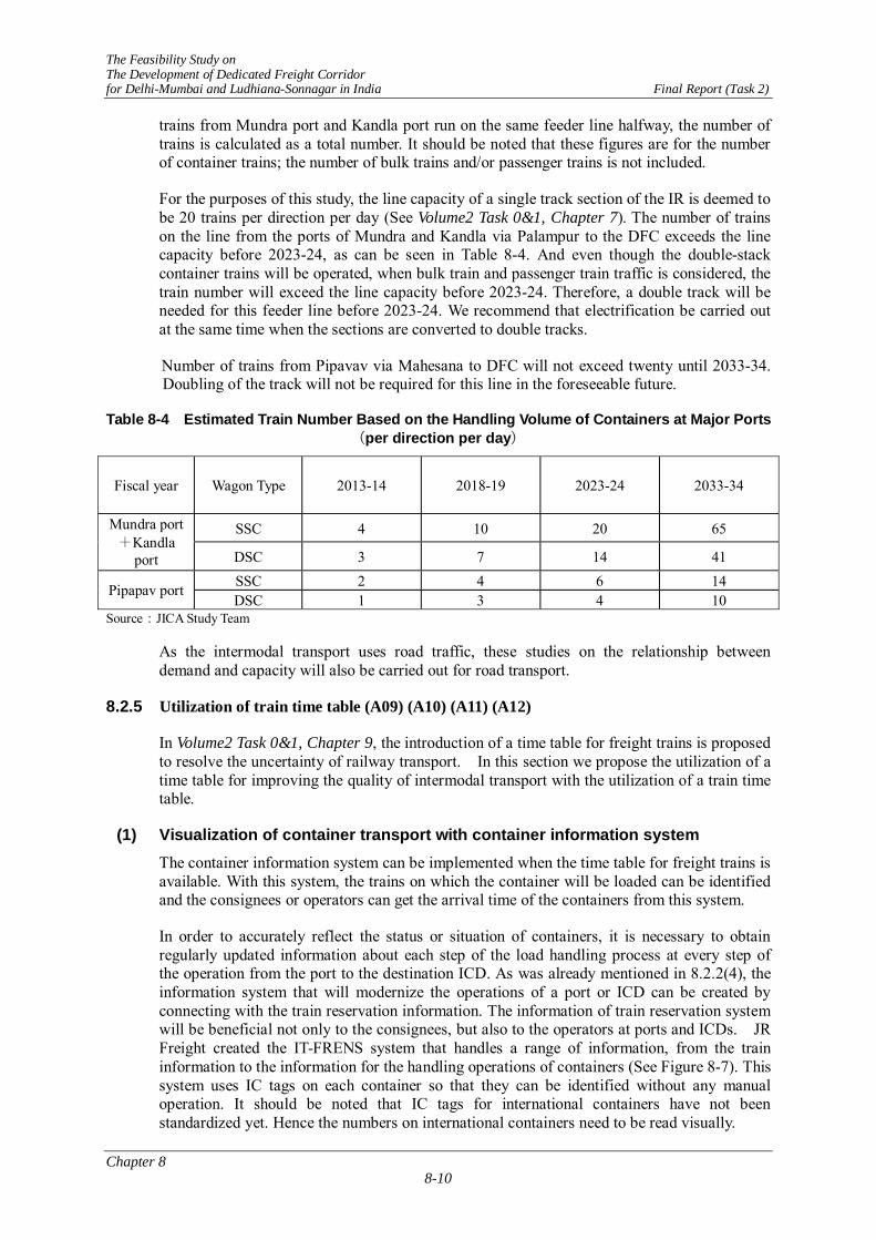
The Feasibility Study on The Development of Dedicated Freight Corridor for Delhi-Mumbai and Ludhiana-Sonnagar in India Final Report (Task 2)
Chapter 8 8-10
trains from Mundra port and Kandla port run on the same feeder line halfway, the number of trains is calculated as a total number. It should be noted that these figures are for the number of container trains; the number of bulk trains and/or passenger trains is not included.
For the purposes of this study, the line capacity of a single track section of the IR is deemed to be 20 trains per direction per day (See Volume2 Task 0&1, Chapter 7). The number of trains on the line from the ports of Mundra and Kandla via Palampur to the DFC exceeds the line capacity before 2023-24, as can be seen in Table 8-4. And even though the double-stack container trains will be operated, when bulk train and passenger train traffic is considered, the train number will exceed the line capacity before 2023-24. Therefore, a double track will be needed for this feeder line before 2023-24. We recommend that electrification be carried out at the same time when the sections are converted to double tracks.
Number of trains from Pipavav via Mahesana to DFC will not exceed twenty until 2033-34. Doubling of the track will not be required for this line in the foreseeable future.
Table 8-4 Estimated Train Number Based on the Handling Volume of Containers at Major Ports(per direction per day)
Fiscal year Wagon Type 2013-14 2018-19 2023-24 2033-34
SSC 4 10 20 65 Mundra port+Kandla
port DSC 3 7 14 41 SSC 2 4 6 14 Pipapav port DSC 1 3 4 10
Source:JICA Study Team
As the intermodal transport uses road traffic, these studies on the relationship between demand and capacity will also be carried out for road transport.
8.2.5 Utilization of train time table (A09) (A10) (A11) (A12)
In Volume2 Task 0&1, Chapter 9, the introduction of a time table for freight trains is proposed to resolve the uncertainty of railway transport. In this section we propose the utilization of a time table for improving the quality of intermodal transport with the utilization of a train time table.
(1) Visualization of container transport with container information system The container information system can be implemented when the time table for freight trains is available. With this system, the trains on which the container will be loaded can be identified and the consignees or operators can get the arrival time of the containers from this system.
In order to accurately reflect the status or situation of containers, it is necessary to obtain regularly updated information about each step of the load handling process at every step of the operation from the port to the destination ICD. As was already mentioned in 8.2.2(4), the information system that will modernize the operations of a port or ICD can be created by connecting with the train reservation information. The information of train reservation system will be beneficial not only to the consignees, but also to the operators at ports and ICDs. JR Freight created the IT-FRENS system that handles a range of information, from the train information to the information for the handling operations of containers (See Figure 8-7). This system uses IC tags on each container so that they can be identified without any manual operation. It should be noted that IC tags for international containers have not been standardized yet. Hence the numbers on international containers need to be read visually.

The Feasibility Study on The Development of Dedicated Freight Corridor for Delhi-Mumbai and Ludhiana-Sonnagar in India Final Report (Task 2)
Chapter 8 8-11
Consignees or consigners of containers can obtain information about the status of their container using this system. It can give information such as whether or not it has completed customs clearance or the location of the train on which their containers are loaded. The visualization of logistics that is mentioned in Volume2 Task 0&1 Chapter 8 will be realized.
Train lo c at ed serv er
ID tag
ID card
IT-FRENS
FRENS
GPS
GPS
A‐2 B‐ 2 C‐2
A‐ 1 B‐1 C‐1
The Internet
The Intranet
dedicated line public line
T R A C E
Forwarder’s company
Firewall
Information of
train location
Forwarder’s office
Forwarder’s
office
Operation center
JR freight
Branch,etc.
Station server
forklift
Driver’sterminal
Container’s y ard
EDI
GPS antenna
SS Radio Antenna
Reader Unit
Sensor for container ID tags
Sensor for freight car and truck ID tags
Mast Sensor
Load Sensor
Monitor Display
Source: JR Freight
Figure 8-7 Container Information System (IT-FRENS & TRACE)
(2) Increasing the frequency of trains to the small ICDs
Precise work scheduling can be planned after the introduction of train time table for freight trains. We propose that the frequency of trains to the small ICDs be increased at this time.

The Feasibility Study on The Development of Dedicated Freight Corridor for Delhi-Mumbai and Ludhiana-Sonnagar in India Final Report (Task 2)
Chapter 8 8-12
At the present time IR uses a unit train system that transports commodities by unit train directly from their origin to their destination. This system was introduced at the time when the traffic capacity was too small for the demand. With this system, the commodities from a station with a transport volume remain at that station until there are enough commodities gathered to fill a train.
This invites a vicious circle: Volume of commodities for transport is small → Train will not leave station until there are enough commodities to fill a train → Arrival time cannot be fixed → Stop using rail → Reduction of commodities shipped by rail. At present, traffic volume in the 300~700 km zone is very small. This seems to be the result of this vicious circle.
Increasing the train frequency for the intermediate stations that currently have small demand will be important for increasing overall container transport in the coming years. CONCOR has already introduced the concept of using combined trains at intermediate station in attempt to solve this problem.
We would like to expand to the combined-train concept. We propose a handling system for containers at the arrival/departure loops at intermediate stations as a method for increasing train frequency at the intermediate stations that currently only have small number of containers to transport. With this system, containers for multiple destinations can be loaded onto a train. JR Freight carries out the loading/unloading of containers at the arrival/departure loops of such intermediate station with only a 20-40 minutes stop (See Figure 8-8 andPhoto: JR Freight
Photo 8-1). To implement this handling system, a time table for freight trains should be introduced and working system that enables all the necessary operations to be carried out punctually according to the working scheme should be made.
The plan is to electrify the DFC. In order to allow forklifts to operate safely under the overhead contact wire at the arrival departure loops, we propose that all forklifts be equipped with a mast lift limiter that would prevent the mast from being raised above a preset height.
Standard Rail Yard
Freight railway station loading at a siding
Source: JICA Study Team
Figure 8-8 Concept of Handling of Containers at the Arrival/departure Loops

The Feasibility Study on The Development of Dedicated Freight Corridor for Delhi-Mumbai and Ludhiana-Sonnagar in India Final Report (Task 2)
Chapter 8 8-13
Photo: JR Freight
Photo 8-1 Handling of Containers at the Arrival/departure Loop of Gifuhajima Station
8.2.6 Installation of Logistic Park (A13)
(1) Function of a logistics park The establishment of a logistics park adjacent an ICD that specializes in transport functions would help increase the amount of container transport. Logistics parks provide the following functions.
a) Custody: Warehousing (general storage, controlled temperature storage)
b) Special services: Sorting, inspection, packaging, unpacking, logistics processing (Disposal yard)
c) Handling: Loading (vanning), unloading (devanning) (Loading/unloading space)
d) Truck depot: Parking lot
A warehouse is a facility for accepting and supplying cargo. The larger its area or capacity, the larger the cargo volume it can handle and the better it can operate like a logistics dam to regulate cargo flow. It is important to establish such warehouses adjacent the ICD so that it can secure stable transport volume and limit fluctuations.
(2) Logistics park at intermediate stations With implementation of Mumbai Delhi Industrial Corridor (MDIC) plan, the area along the DFC will also be developed. New industries will grow up along the DFC. They will process materials from one region to make products that will be sent to another region or even exported. (See Figure 8-9).
Both container trains and bulk trains will come from Delhi, JNP and Gujarat to stations along this industrial corridor. The handling of containers at the arrival/departure loops of intermediate stations is proposed in 8.2.5(2). Logistics park functions can be also attached to these intermediate stations to promote new industries around an ICD.

The Feasibility Study on The Development of Dedicated Freight Corridor for Delhi-Mumbai and Ludhiana-Sonnagar in India Final Report (Task 2)
Chapter 8 8-14
Source: JICA Study Team
Figure 8-9 Container Commodities Flow When Logistics Park is Available
8.2.7 Improvement of ICD Functions (A13 and A15)
ICD is a general interchange connecting with railway transport and truck transport. Improvement of ICD functions is the most important issue for intermodal transport, because increasing time-consuming work by handling process at ICD is one of tough issues for railway transport .
The other hand, Indian Railways signed a concession agreement with 15 container train operators in January 2007 that is expected to improve goods transportation and help rail freight revenues rise several fold. This signing heralds a new era in giving a legal shape to mutual relations, rights and responsibilities between the Indian Railways and the container train operators. (refer to Volume 2 Task0&1 Chapter 4)
(1) Function of ICD ICD is one of bases of distribution facility and it has the following functions.
- To pass custom clearance;
- To issue the invoice for cargos between port and ICD and to set freight charges;
- To unload and load containers;
- To operate freight trains from/to ports;
- To transport containers by trains between ICD and small scale of ICD or CFS (Container Freight Station);
- To operate empty containers; and
- To maintain and clean containers
There can also be an idea to grade up ICD’s to have Logistic Park functions with addition of the various services for cargo flow assistance. These are cargo storage under safety inspection, cargo inventory, palletization including shrink-packing, and box-packing with marking, etc. in addition to the general warehousing. Refrigerated and chilled cargo can be kept in storage and reefer container operation can be carried out if refrigerated power is equipped here.

The Feasibility Study on The Development of Dedicated Freight Corridor for Delhi-Mumbai and Ludhiana-Sonnagar in India Final Report (Task 2)
Chapter 8 8-15
It is desirable that ICD has not only the role of container loading/unloading operation and delivery but also additional services on request of cargo owners. ICD is divided in several modules so that the container inter-modal operators in each module may have competition to get customers. These modules are for lease/concession to container inter-modal operators who have got licenses from Government in 2006 on their request. The competition will surely induce containers to railway route and produce new prosperity and economic demand.
Customs, immigration, shipping companies, forwarders and other related offices are located in and around ICD for their quick and smooth service and documentation. Individual container inter-modal operator may have its own office, CFS, checking gate for container, stacking yards reefer container receptacles and maintenance shops in accordance with its service policy to customers in the module.
(2) Cargo-handling Equipment and Devices Main cargo-handling equipments and devices in ICD are as follows;
- Rail Gantry Cranes
- Rubber Tyred Gantry Cranes
- Reach Stackers
- Forklift
- Tractor Trailers
Characteristics of operation by gantry crane are flexible cargo handling in any place soever, and at the same time, high procurement cost and low handling speed. Meanwhile, characteristics of forklift are possibility of making small adjustments and low cost and high handling speed, however, inability for behind side cargo. Hence, layout and number of each cargo-handling equipment and device should be planned effectively in consideration of these performances.
8.2.8 ICD in the proximity of NCR (A14)
(1) Necessity of New ICD in the proximity of NCR At present, there are two major ICDs in NCR of Delhi, namely, TKD and Dadri. These two ICDs are operated by CONCOR and their total container handling capacity is 1.4 million TEUs per annum. Other than above two ICDs, CONCOR operates 3 ICDs and Gateway operates one ICD in NCR of Delhi, however, the size of these ICDs are relatively small.
Despite the above condition, RITES has forecasted future container traffic demand in 2021/22 in NCR of Delhi as 4 million TEUs per annum or 65 container trains per day in their PETS-II report. To manage the above future container demand, RITES suggested that two more mega ICDs should be constructed in southern area in NCR of Delhi.
On the other hand, the new proposed section to be constructed from Rewari to TKD and Dadri will include a large-size ICD that has been proposed in Phase II in the year 2015/16, because it is assumed it will take a long time for additional land acquisition, compensation for PAPs, EIA survey and so on. Hence, new ICD may be planned within a radius of 30 kilometres from the centre of Delhi for collection and delivery of freight around Delhi without delay till Phase II is operational.
(2) Container Throughput of ICDs The container throughput of the existing ICDs in NCR and the estimated future demand of freight are as follows;
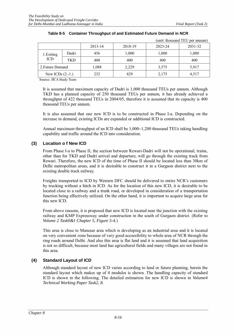
The Feasibility Study on The Development of Dedicated Freight Corridor for Delhi-Mumbai and Ludhiana-Sonnagar in India Final Report (Task 2)
Chapter 8 8-16
Table 8-5 Container Throughput of and Estimated Future Demand in NCR
(unit: thousand TEU per annum) 2013-14 2018-19 2023-24 2031-32
Dadri 456 1,000 1,000 1,000 1.Exiting ICD TKD 400 400 400 400
2.Future Demand 1,088 2,229 3,575 5,917
New ICDs (2.-1.) 232 829 2,175 4,517 Source: JICA Study Team
It is assumed that maximum capacity of Dadri is 1,000 thousand TEUs per annum. Although TKD has a planned capacity of 250 thousand TEUs per annum, it has already achieved a throughput of 422 thousand TEUs in 2004/05, therefore it is assumed that its capacity is 400 thousand TEUs per annum.
It is also assumed that one new ICD is to be constructed in Phase I-a. Depending on the increase in demand, existing ICDs are expanded or additional ICD is constructed.
Annual maximum throughput of an ICD shall be 1,000~1,200 thousand TEUs taking handling capability and traffic around the ICD into consideration.
(3) Location o f New ICD From Phase I-a to Phase II, the section between Rewari-Dadri will not be operational, trains, other than for TKD and Dadri arrival and departure, will go through the existing track from Rewari. Therefore, the new ICD of the time of Phase II should be located less than 30km of Delhi metropolitan areas, and it is desirable to construct it in a Gurgaon district next to the existing double track railway.
Freights transported to ICD by Western DFC should be delivered to entire NCR’s customers by trucking without a hitch in ICD. As for the location of this new ICD, it is desirable to be located close to a railway and a trunk road, or developed in consideration of a transportation function being effectively utilized. On the other hand, it is important to acquire large area for this new ICD.
From above reasons, it is proposed that new ICD is located near the junction with the existing railway and KMP Expressway under construction in the south of Gurgaon district. (Refer to Volume 2 Task0&1 Chapter 5, Figure 5-4.)
This area is close to Manesar area which is developing as an industrial area and it is located on very convenient zone because of very good accessibility to whole area of NCR through the ring roads around Delhi. And also this area is flat land and it is assumed that land acquisition is not so difficult, because most land has agricultural fields and many villages are not found in this area.
(4) Standard Layout of ICD Although standard layout of new ICD varies according to land or future planning, herein the standard layout which makes up of 4 modules is shown. The handling capacity of standard ICD is shown in the following. The detailed estimation for new ICD is shown in Volume4 Technical Working Paper Task2, 8.
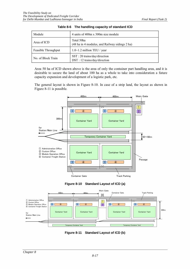
The Feasibility Study on The Development of Dedicated Freight Corridor for Delhi-Mumbai and Ludhiana-Sonnagar in India Final Report (Task 2)
Chapter 8 8-17
Table 8-6 The handling capacity of standard ICD
Module 4 units of 400m x 300m size module
Area of ICD Total 50ha (48 ha in 4 modules, and Railway sidings 2 ha)
Feasible Throughput 1.0~1.2 million TEU / year
No. of Block Train SST : 20 trains/day/direction DST : 12 trains/day/direction
Area 50 ha of ICD shown above is the area of only the container part handling area, and it is desirable to secure the land of about 100 ha as a whole to take into consideration a future capacity expansion and development of a logistic park, etc.
The general layout is shown in Figure 8-10. In case of a strip land, the layout as shown in Figure 8-11 is possible.
Main Gate
forStation/Main Line
① Administration Office② Custom Office③ Module Operation Office④ Container Freight Station
Passage
Container Gate Track Parking
③ ④
Container Yard
③ ④
Container Yard
Temporary Container Yard 50~60m
400m 400m
300m
③ ④
Container Yard
③ ④
Container Yard
①
②
Figure 8-10 Standard Layout of ICD (a)
Main GateContainer Gate Track Parking
① Administration Office② Custom Office③ Module Operation Office④ Container Freight Station
forStation/Main Line
③ ④
Container Yard
③ ④
Container Yard
Temporary Container Yard
400m 400m
300m
①
② ③ ④
Container Yard
③ ④
Container Yard
Temporary Container Yard
Figure 8-11 Standard Layout of ICD (b)

The Feasibility Study on The Development of Dedicated Freight Corridor for Delhi-Mumbai and Ludhiana-Sonnagar in India Final Report (Task 2)
Chapter 8 8-18
(5) Construction and Operation of ICD New ICD shall be constructed for collection and delivery freights around Delhi without delay as long as it coincides with the opening time of Phase I-a. New ICD in Phase I-a of DFC should be prepared and then should be leased to the operators by DFCCIL, because of the following reasons;
- New ICD plan in NCR by the operators is not known and
- Opening time of new ICD shall be decided by the stage construction plan and schedule of Western DFC.
However, future ICD plan after Phase II shall be relegated to the operators, because it will be assumed that operators have know-how needed to substantially physical distribute by themselves, and it is not easy to predict future domestic situation and global trends today.
Cargo-handling equipments in ICD as gantry crane, reach stacker, forklift and so on shall be provided by DFCCIL and leased to operators, because of the following reasons;
- Each operator will waste time by the interval of each freight train, if different operators will lease each module in ICD and
- It is very tough to hire these equipments in ICD from other place.
General transporting machine from container yard such as truck and trailer shall be arranged by operators.
8.2.9 Railway and Road Access to ICD (A16)
In this clause, improvement of access railway and road to aforesaid ICD in the proximity of NCR is mentioned.
(1) Railway Access In case of new ICD constructed in Gurgaon district, feeder line between Rewari and Gurgaon is necessary. The existing line from Rewari to Delhi via Gurgaon can be used for the feeder line. This line is non-electrified and has two single lines of broad-gauge and one meter gauge. Now conversion from meter gauge to broad gauge is ongoing, then operation for double track of broad gauge can commence along with DFC Phase I-a.
The station near by for receiving and shunting freight container trains is necessary near an ICD.
(2) Road Access Access roads to ICD shall be planned to connect to Delhi Ring Road, KMP Expressway and KGP Expressway, for supporting functions of circulation and accessibility to NCR.
The number of lanes on access road shall be more than 4-lane carriageways with wide paved shoulder, because not only truck and trailer but also sedan and low speed vehicle will utilize this road. And the sidewalk on both sides and medium along this road shall be installed to ensure the safety for pedestrian and bicycles. Especially, buffer zone for protection of children and pedestrians from heavy vehicles such as truck and trailer, shall be installed between traffic lane and sidewalk near school, hospital, park, and so on.
The pavement of these roads should be designed for sufficient bearing force in consideration of the future heavy vehicle demand. And periodical patrol and maintenance are critical to keep the good condition and for extension of the life span of pavement.

The Feasibility Study on The Development of Dedicated Freight Corridor for Delhi-Mumbai and Ludhiana-Sonnagar in India Final Report (Task 2)
Chapter 8 8-19
8.2.10 Collaboration with truck delivery (A17) (A18)
After the arrival at an ICD, containers will be delivered to the consignees by trucks. Most of road companies in India are medium or small enterprises. It was reported to JST that some companies use dilapidated trucks that have failures that delay the delivery of the cargo. The cargo is also occasionally damaged because of the condition of the trucks. (Volume2 Task 0&1 Chapter 9, Table 9.4) Consigners who use containers frequently have relationships with trusted truck companies. Consigners who seldom use container transport have the monumental task of finding a good trucking company with a reliable fleet of trucks.
To improve the quality of intermodal transport, the system with which consigners can easily use container transport in totality should be introduced. A system that can recommend good truck companies or even provide one-stop service of transport by railway operator would help solve this problem.
Note; one-stop service is to provide all the necessary transport arrangements as part of single “package.”
(1) Recommendation of system of good truck companies by railway operator
The railway operator has the best information about the quality of truck companies that can reliably pick up and deliver the containers. The railway operator is in a position to start a service in which it recommends reliable truck companies to its customers. This will make the trucking companies more competitive and ultimately raise the quality of service provided by all of them.
(2) One-stop service of container transport
Ideally a system would be arranged that provided one-stop service of container transport from the port to its final destination, including the customs clearance on behalf of the customers. Intermodal transport will provide more transport measures that are easy for consigners to use.
When this one-stop service is provided by railway operators, consigners will not be required to make contracts with numerous companies and this will dramatically reduce both effort and paper work. Consigners can use this one-stop for container transport with peace of mind because the provider of the service will bear the responsibility of total transport. While the provider does have total responsibility for the transport, it can use its role to gather more information about the needs of the consigners from the trucking companies and develop services that can fulfill those needs.
When the trucking companies are working for the railway companies, the railway companies will also have the ability to quickly acquire trucks and respond when there is a seasonal fluctuation or disruption on the rail lines.
8.2.11 Establishing credit guarantee system (A19)
Railway tariffs are paid in advance by shippers so the railway operators never fail to get compensated. This system reduces the risk against railway operators and it is beneficial to them.
However, it is not so beneficial to the customers. Providing the money for the tariff in advance places a financial strain on the shipper. We propose that the introduction of a tariff clearance system. This system has been implemented for many years in Japan, as can be seen in Volume2 Task 0&1 Chapter 9, 9.4.2. We recommend the establishment of credit guarantee organizations to prevent all the risk from being born by the railway operators. It will cover the risk of a consigner not being able to pay his tariff. This organization will pay the debt on

The Feasibility Study on The Development of Dedicated Freight Corridor for Delhi-Mumbai and Ludhiana-Sonnagar in India Final Report (Task 2)
Chapter 8 8-20
behalf of such a consigner, as this organization performs a role similar to that of an insurance company.
8.2.12 Introduction of individual negotiation system with tariff (A20)
CONCOR introduced a special tariff between JNP and Delhi for a limited time only in order to compete with road transport. CONCOR also offers a quantity discount system for domestic container transport. Both are officially announced and individual negotiation is not yet possible.
Tariff setting should not develop into price war. However, as each customer has unique needs, a uniform tariff may hamper the acquisition of customers. Truck companies negotiate individually with customers and determine the tariff through communication. To compete with truck companies, CONCOR has to develop a system that allows CONCOR to negotiate transport conditions and tariffs with major customers.
8.3 TARGETED VALUE BY IMPROVEMENT OF INTERMODAL TRANSPORT
How much will the above measures improve inter-modal transport? We attempted to answer this question by making an estimate based on data about import containers. The assumptions for the estimate are as follows.
- Required time in port: 24 hours based on the result in Japan
- Required time in ICD: 48 hours with consideration only for customs clearance
- Delivery time from ICD: 6 hours from ICD (Delivery distance is assumed to be within 100km)
- Travel time by railway: Based on the results in Chapter 6, 6.11 of Volume3 Task2.
Table 8-7 Required Travel Time for Inter-modal Transport after Improvement
Unit:hours Required
time at port
Transport time on
feeder line
Transport time on
DFC
Required time at
ICD
Delivery time from
ICD Total
JNP‐Delhi 24 0 21 48 6 99JNP-Ludhiana 24 6 20 48 6 104Mundra- Delhi 24 7 12 48 6 97Pipavav-Delhi 24 8 13 48 6 99
Rail 168 47 0 96 6 317JNP-Delhi (In average at Present) Road 48 120 0 0 0 168
Source: JICA Study Team
As it can be seen in Table 8-7, with the improvement of intermodal transport, the best case scenario is that the total transport time will be reduced to approximately one third that of the present transport time. At present it is said that transport by road offers the fastest transport time, but after these improvements, rail will be able to offer many advantages including the fastest transport time.
In this report, these estimated figures should be treated as the target values for the improvements of working system at port and ICD.

The Feasibility Study on The Development of Dedicated Freight Corridor for Delhi-Mumbai and Ludhiana-Sonnagar in India Final Report (Task 2)
Chapter 8 8-21
8.4 CONSOLIDATION PLAN AND EVALUATION
8.4.1 Method and Subject of Evaluation
(1) Evaluation Method Consolidation plan for intermodal transport has been suggested centring on ICD and ports. Effects of these suggestions on changes before and after consolidation were evaluated focusing on the following 4 points.
Table 8-8 Consolidation Plan for Inter-modal Transport
Consolidation Subject
Before After Saving Classification of Effects
ICD 4-5 days 2 days 2 days Time saving of container cargo handling Port 5-8 days 1 day 5 days Storage fee saving of container cargo
Access Road 10km/h 30km/h 20km/h Time saving of truck cargo Cost saving of truck operating cost
(2) Subject of Evaluation The distance of Western DFC from Mumbai to Rewari is 1,351km. The distance from Rewari to optimal ICD site in the capital zone of Delhi is 117km, further. Construction costs of this corridor of 117km is estimated at 29,950Million Rs. In the case that this investment of 29,950Million Rs. is not implemented (without), container cargos have to be transported either by the existing railroad or by trucks.
In the case that DFC construction is implemented (with), benefits of solving the problem of traffic congestion and of saving time will generate. Therefore in order to ease traffic congestion, access to ICD of this section will be a necessary condition. For access to the metropolitan ICD from Rewari, in addition to DFC other alternative methods can be considered such as utilization of ring road and widening of existing road.
However, this is an independent investment justification study for only DFC 113km section, costs-benefits analysis is not carried out. Origin and destination of cargoes are mainly in the metropolitan zone Delhi. For loading and unloading of cargoes to deliver by trucks from Rewari, 117km away is too far from ICD. Economic evaluation for this section is to be included in 1,468km of trunk road of Mumbai-Rewari.
The evaluation will be conducted only for ICD of metropolitan at both ends of DFC, and for ports (see Chapter12, Economic and Financial analysis).
8.4.2 Cargo volume to use ICD and Ports
Total volume of cargo handled at ICD of metropolitan area is shown below, as described in Table 8-5 ”Annual cargo volume handled by containers at ICD in Delhi area”. For the number of trucks 1 TEU is converted to 13tons, and In・Out truck freight is converted to 10 tons.
2012-14: 1,090Thousand TEU/year 38,750 ton/day 7,750 vehicles/day2018-19: 2,230Thousand TEU/year 79,390 ton/day 15,880 vehicles/day2023-24: 3,580 Thousand TEU/year 127,330ton/day 25,470 vehicles/day2031-32: 5,920 Thousand TEU/year 210,740ton/day 42,150 vehicles/day

The Feasibility Study on The Development of Dedicated Freight Corridor for Delhi-Mumbai and Ludhiana-Sonnagar in India Final Report (Task 2)
Chapter 8 8-22
8.4.3 Time Reduction by Improvement of physical-distribution System
According to “Physical-Distribution Improvement Flow Chart” as in Volume 2 Chapter9, 9-4, arrival cargo before improvement will be kept for 5-8 days at the port and 4-5 days at ICD. After improvement the period will be reduced to 1 day at the port, and 2 days at ICD. At least 5 days at the port and 2 days at ICD will possibly be reduced.
The methods of reduction are improvement of investment in plant and equipment, introduction of distribution system, consolidation of business, improvement of working methods, and etc. For the ports, they are increase of berth, expansion of container-yard, consolidation of yard, consolidation of customs clearance, closer connection of trains and loading, improvement of railroad wiring, improvement of feeder railroad, and etc.. For ICD, they are scheduled operation of trains, mechanization of warehouse loading, improvement of access road, introduction of small-scale delivery base, expansion and building of ICD, introduction of container reservation system, etc.
8.4.4 Amount of Benefits
(1) Amount of Time Reduction Benefit of Cargoes The cost of cargo kept for 1 hour is estimated at 0.0432Rs per ton, per hour. This time unit value of kept-cargo was calculated in the following method. The main cargo is import-export cargoes. According to import-export statistics, the average price of these cargoes is 4,052Rs per ton. Cargo stock due to transport delay costs by hour. Therefore, cargo price per ton was obtained by multiplying short-period interest (11% per year). Economic price multiplied by conversion coefficient of 0.85 is 0.0432 Rs.
As the result, time reduction benefit is as follows. The total sum of benefit for ICD. Port in years 2018-19 at 95% opening of DFC is 210 Million Rs. It equals to 24% of 874 Million Rs time saving of the JNP-Dadri trunk line of DFC. (See table below)
(Rs. Million) 2013-14 2018-19 2023-24 2031-32 1) Time-saving benefits of ICD 29 60 96 160 2) Time-saving benefits of port 73 150 241 399
(2) Time Saving Benefit of Stock Fee of Cargo For regularly transporting goods (parts, manufactured goods, transferred goods), they must be kept in stock in advance by the side of arrival according to time needed for arrival. For example, as to the goods that arrive in 7 days, 7 day’s goods must be in stock. Place for the stock is necessary. Storage fee will be levied in order to secure the place for the stock.
Storehouse is lent out at a charge by m2. This is difficult to convert to weight, and storage charge of containers is used here. As to the storage charge of containers per 1 TEU per day, the tariff charge of 200Rs./1 TEU・1 day, was applied from ACTL Corporation in Faridabad in the suburbs of TKD since 1997. To be converted to per 1 hour, it equals to 0.641/hour per ton. (Unit: Million Rs.)
2013-14 2018-19 2023-24 2031-32 1) Saving benefit of ICD storage 434 890 1,427 2,361 2) Saving benefit of time of port 1,086 2,224 3,567 5,904

The Feasibility Study on The Development of Dedicated Freight Corridor for Delhi-Mumbai and Ludhiana-Sonnagar in India Final Report (Task 2)
Chapter 8 8-23
(3) Benefit by Improvement of Access Road Access road of TKD located at 12km point from the central part of the capital becomes congested for the worst over 3km with distribution vehicles. Supposedly, on this 3km section driving speed of 10km/h in the condition of “without” is improved to 30km/h in the condition of “with”, saving benefit of traveling cost for trucks and saving benefit of time for transported goods generate.
The relational equation between Traveling speed (x) and traveling cost (Y) is calculated in the same way as DFC trunk road.
Truck = 0.003464x2 – 0.452039x + 24.768072 + 3.35
The total benefit of ICD and port is estimated as below. Time saving benefit of cargo is small, but saving benefit of traveling cost of trucks is very high. (Unit: Million Rs.)
2013-14 2018-19 2023-24 2031-32 1) Saving benefit of traveling cost 106 218 350 579 2) Saving benefit of time of cargo 49 100 161 266
8.4.5 Total Benefits
The total benefits of improvement by saving of 2days at ICD ground and 5days at the port, and by reduction of congestion of the access road from 10km/h to 30km/h, is shown below. Figure 8-12 is a graph to indicate the above 4 benefits adding time saving benefit of DFC 1,468km that use metropolitan ICD, and operating cost benefit.
0
5000
10000
15000
20000
25000
1 3 5 7 9 11 13 15 17 19 21 23 25 27 29
Access.
VOC
DFC
Port
ICD
Figure 8-12 Saving Cost Benefit by Improvement of physical distribution system.
Explanation of the graph:
1) Access Road: Time saving benefit of 10ton-distributing trucks in the case that 3km of near-by road is improved from 10km/h to 30km/h. (The amount is too small for the graph to show).
2) Vehicle Operating Cost (VOC): Traveling cost saving in the same condition as above.
3) DFC: Time saving + operating cost saving in the case that 1,468km of DFC is used.
(Excluding benefits of trucks and buses, and of CO2 saving benefit)
4) Port: Time saving benefit and storage charge saving benefit at 5 days’ reduction of keeping containers for the same quantity as ICD.

The Feasibility Study on The Development of Dedicated Freight Corridor for Delhi-Mumbai and Ludhiana-Sonnagar in India Final Report (Task 2)
Chapter 8 8-24
5) ICD: Time saving benefit and storage charge saving benefit at 2 days’ reduction of keeping cargoes.
The total benefit of 35 years of the above 4 items is 209,182 Million Rs. Time saving benefit of DFC trunk line is excluded here, since it is included in calculation of EIRR of the main railroad. The present value discounted at the capital opportunity cost, 12%, is 23,167Million Rs. (Unit: Million Rs).
2013-14 2018-19 2023-24 2031-32 Total ICD benefit (present value) 307 357 325 217 7,053 Port benefit(present value) 702 816 742 496 16,114
8.4.6 Overall Considerations
From estimations above, it is concluded as follows.
1) Total ICD benefit of 7,053 million Rs at the present value shows the B/C ratio of 2.4 in comparison with 3000 million Rs. of New ICD construction at the scale of 1000-1200TEU. Consolidation of ICD will generate very big effects with small investment of plant and equipment.
2) This was compared with saving benefit of DFC main railroad line as follows. ICD benefit (present value), 7,053 million Rs. is more than DFC time saving benefit, and total benefit adding 16,114 of port benefit (present value) is 22% to DFC operating cost saving benefit.
ICD benefit (present value) Total 7,053 = DFC Time saving benefit 4,561
Port benefit (present value) Total 16,114 = DFC Operating cost saving benefit 72,103
3) Conditions for benefits estimation is set at ‘Before’ and ‘After’. If the conditions are changed to ‘With’ and ‘Without’, benefits will more increase.
For cost reduction, besides keeping time reduction of cargoes, there must be other savings such as ICD management cost, plant and equipment cost, cost of spoiling of goods, and opportunity loss. Those effects will increase more if competitive principle works. Inter-modal effects may be considered to further produce larger indirect external economic effects.
The following effects maybe considered as indirect economic and social effects, which is difficult to measure.
1) Existing ICD and new ICD candidate site will be located at industrial estate and areas with high potential for development. Operation of ICD will rise land prices by newly established transport businesses such as distribution centre, and by activation of commercial businesses. This is a big indirect economic effect, and will promote activation of nearby area’s economy.
2) Import-Export goods will be dispatched and distributed more quickly, regularly, without damage, and efficiently. This will increase economic and social influence effects, such as value of using cargoes for both dispatchers and distributors, increase cost reduction of transport enterprises, increase credibility of enterprises.
3) Time saving of ICD affects advantageously in competition with truck transport, and will expand railroad transport areas. This consequently will increase railroad transport volume and railroad passengers.
4) Reduction of 7 days of keeping containers the required area for containers will be drastically reduced, that makes it possible to save land purchase cost, and to operate efficiently.
5) ICD carries out mainly the role of railroad station and distribution centre, and well planned arrangement will increase effects to reduce urban traffic congestion.

The Feasibility Study on The Development of Dedicated Freight Corridor for Delhi-Mumbai and Ludhiana-Sonnagar in India Final Report (Task 2)
Chapter 8 8-25
6) This study was conducted on container cargoes of the port in Delhi metropolitan area, but if it includes domestic container cargoes saving benefit scale will be larger.

The Feasibility Study on The D
evelopment of D
edicated Freight Corridor for D
elhi-Mum
bai and Ludhiana-Sonnagar in India Final Report (Task 2)
Chapter 8
8-26
Table 8-9 Calculation for Im
provement Effects of Interm
odal Transport
Access GroundYear Year 1day ICD Port ICD Port In・Out Year Time Total ICD Port
2days/y 5days/y 2days/y 5days/y No.of Without With Saving Saving Saving Saving Saving Time Working Ex.1000TEU 1000ton Ton Mill.Rs. Mill.Rs. Mill.Rs. Mill.Rs. Truck/day 1000Rs. 1000Rs. Mill.Rs. Year Mill.Rs. Mill.Rs. Mill.Rs. Saving Saving
2008-09 100%2009-10 89%2010-11 80%2011-12 71%2012-13 64%2013-14 1,088 14,144 38,751 29 73 434 1,086 7,750 555 409 106 49 1,778 57% 307 702 581 6,5362014-15 1,256 16,326 44,728 34 85 501 1,253 8,946 640 472 123 56 2,052 51% 317 723 550 6,0912015-16 1,450 18,844 51,626 39 98 578 1,446 10,325 739 545 142 65 2,369 45% 326 745 519 5,6722016-17 1,673 21,750 59,589 45 113 668 1,669 11,918 853 629 164 75 2,734 40% 336 768 489 5,2792017-18 1,931 25,105 68,780 52 130 771 1,927 13,756 984 726 189 87 3,156 36% 346 792 460 4,9102018-19 2,229 28,977 79,389 60 150 890 2,224 15,878 1,136 838 218 100 3,642 32% 357 816 281 4,6632019-20 2,450 31,848 87,256 66 165 978 2,444 17,451 1,249 921 240 110 4,003 29% 350 800 241 4,1952020-21 2,693 35,004 95,902 73 182 1,075 2,687 19,180 1,373 1,012 263 121 4,400 26% 344 786 206 3,7712021-22 2,959 38,473 105,405 80 200 1,181 2,953 21,081 1,509 1,112 289 133 4,836 23% 337 771 174 3,3882022-23 3,253 42,285 115,849 88 219 1,298 3,245 23,170 1,658 1,222 318 146 5,315 20% 331 756 146 3,0422023-24 3,575 46,475 127,329 96 241 1,427 3,567 25,466 1,822 1,343 350 161 5,842 18% 325 742 123 2,7342024-25 3,807 49,496 135,606 103 257 1,520 3,799 27,121 1,941 1,431 372 171 6,222 16% 309 706 109 2,4902025-26 4,055 52,714 144,422 109 274 1,618 4,046 28,884 2,067 1,524 397 182 6,626 15% 294 671 97 2,2672026-27 4,319 56,141 153,811 117 291 1,724 4,309 30,762 2,201 1,623 422 194 7,057 13% 279 638 86 2,0632027-28 4,599 59,790 163,810 124 310 1,836 4,589 32,762 2,345 1,728 450 207 7,516 12% 266 607 75 1,8772028-29 4,898 63,677 174,459 132 330 1,955 4,887 34,892 2,497 1,841 479 220 8,004 10% 253 577 66 1,7072029-30 5,217 67,817 185,800 141 352 2,082 5,205 37,160 2,659 1,960 510 235 8,525 9% 240 549 56 1,5402030-31 5,556 72,226 197,879 150 375 2,217 5,543 39,576 2,832 2,088 543 250 9,079 8% 228 522 47 1,3902031-32 5,917 76,921 210,742 160 399 2,361 5,904 42,148 3,016 2,223 579 266 9,669 7% 217 496 37 12232031-33 5,917 76,921 210,742 160 399 2,361 5,904 42,148 3,016 2,223 579 266 9,669 7% 194 443 33 10922033-34 5,917 76,921 210,742 160 399 2,361 5,904 42,148 3,016 2,223 579 266 9,669 6% 173 396 29 9752034-35 5,917 76,921 210,742 160 399 2,361 5,904 42,148 3,016 2,223 579 266 9,669 5% 155 353 26 8712035-36 5,917 76,921 210,742 160 399 2,361 5,904 42,148 3,016 2,223 579 266 9,669 5% 138 315 23 7782036-37 5,917 76,921 210,742 160 399 2,361 5,904 42,148 3,016 2,223 579 266 9,669 4% 123 282 21 6942037-38 5,917 76,921 210,742 160 399 2,361 5,904 42,148 3,016 2,223 579 266 9,669 4% 110 251 19 6202038-39 5,917 76,921 210,742 160 399 2,361 5,904 42,148 3,016 2,223 579 266 9,669 3% 98 224 17 5532039-40 5,917 76,921 210,742 160 399 2,361 5,904 42,148 3,016 2,223 579 266 9,669 3% 88 200 15 4942040-41 5,917 76,921 210,742 160 399 2,361 5,904 42,148 3,016 2,223 579 266 9,669 3% 78 179 13 4412041-42 5,917 76,921 210,742 160 399 2,361 5,904 42,148 3,016 2,223 579 266 9,669 2% 70 160 12 3942042-43 5,917 76,921 210,742 160 399 2,361 5,904 42,148 3,016 2,223 579 266 9,669 2% 62 143 11 352
Total 128,011 1,664,144 4,559,299 3,455 8,637 51,089 127,723 911,860 65,255 48,104 12,520 5,758 209,182 12% 7,053 16,114 4,561 72,103
Time Saving Storage Fee Saving Vehicle Operating Cost Saving Million Rs.
V.O.CYear
Discounted Present ValueDFC Train
Western DFC (ICD,Port,Acces Road) Traffic Volume(JNP-ICD)
Discount Rate

The Feasibility Study on The Development of Dedicated Freight Corridor for Delhi-Mumbai and Ludhiana-Sonnagar in India Final Report (Task 2)
Chapter 8 8-27
8.5 ACTIONS REQUIRED FOR IMPROVEMENT OF INTERMODAL TRANSPORT
8.5.1 Basic Policy
As presented in Table 8-1, many organizations other than railway companies are relevant in the railway container transport system, which constitute the overall transport service. If transport services can be managed by a single organisation, the improvement of service based on customer needs can be done by effort of this organisation. However, in case of railway transport, since there are many tasks that need to be endorsed to other organisations than railway companies, it is difficult to take action to improve the entire service. DFCCIL and MOR requires to take initiatives to solve the above underlying issues of railway transport, and be determined that the railway transport system in India will be drastically reformed by the DFC Project.
Based on the above recognition, the JST proposes the establishment of “Task force for the Improvement of the Intermodal Transport” by DFCCIL, MOR and other relevant agencies to work out a concrete action plan for the cross-organizational issues mentioned above. The JST recommends that issues to be dealt by DFCCIL and MOR be included in the scope of DFC Project. However issues outside scope of the Project be implemented as a separate project, but in tandem with the progress of the DFC Project.
8.5.2 Establishment of Task Force for Improvement of Intermodal Transport and Approach to Other Organisation
The Task Force to improve the intermodal transport is recommended to be established by the JST. The objective of its establishment is to prepare a policy to secure the competitiveness of the railway container transport on the Western DFC, and implement the policy with the cooperation of other related organisation. It is suggested that in addition to the organisation tabulated in Table 8-1, organisation such as the Federal Government, relevant Ministries and agencies, representatives of customers, and academics can become member of the task force.
The proposed members of the Task Force may be as follows.
1) Representative of Ministry of Railways (Chairman)
2) Representative of Ministry of Shipping and Road
3) Representative of Ministry of Commerce and Industry
4) Representative of Planning Commission
5) Representative of DFCCIL
6) Representative of Port Authorities
7) Representative of Port operators
8) Representative of Logistics operator
9) Representative of State Government
10) Representative of Academics
11) Representative of customer (Manufacturers)
It is desired that the Task Force be established at the earliest as possible, and that implementation of other related project be completed simultaneously with the Phase I-a Project.

The Feasibility Study on The Development of Dedicated Freight Corridor for Delhi-Mumbai and Ludhiana-Sonnagar in India Final Report (Task 2)
Chapter 8 8-28
8.5.3 Action to be undertaken by DFCCIL and MOR
The tasks to be undertaken by DFCCIL and MOR in railway transport system in western DFC are proposed in the following paragraphs. As was clarified in the section presenting the establishment of the phased development scenario, the DFC will terminate at Rewari in Phase I-a, and connection to TKD and Dadri will remain cut off. Thus, the provision of a new ICD between Rewari and Gurgaon is a prerequisite condition of Phase I-a that materialises the container transport. Due to its significance, the JST included this in the scope of the Project, and recommends that the works should not be endorsed to other organisation but DFCCIL should take initiative.
1) Tasks to be undertaken by DFCCIL
a) Construction, operation, and maintenance of DFC
b) Train operation management and information sharing
c) Construction of ICD infrastructure between Rewari and Gurgaon, and attract ICD operators
2) Tasks to be undertaken by MOR
d) Electrification of Rewari – Gurgaon – Brar Square / Patel Nagar section
e) Construction of bypass line between Delhi Cantt – Brar Square (Improvement of connectivity to ICD of TKD and Dadri via existing lines)
f) Strengthening of transport capacity of existing line between Vadodara – Vasai Rd (Signal improvement and track layout improvement)
g) Replacement and procurement of locomotives
It is suggested that item a), b) and c), which are prerequisites for the viability of the Project, be included in the scope of the Project and implemented. Clarification of item C is made in the subsequent section where the result of the basic study regarding the location, size, and facilities, are introduced.
It is desired that item e), f), and g) be implemented by MOR in conjunction to the DFC Project.

CHAPTER 9 OPERATION AND MAINTENANCE PLANNING

The Feasibility Study on The Development of Dedicated Freight Corridor for Delhi-Mumbai and Ludhiana-Sonnagar in India Final Report (Task 2)
Chapter 9 9-1
CHAPTER 9 OPERATION AND MAINTENANCE PLANNING
9.1 PURPOSE OF THIS CHAPTER
The implementation of the operation and maintenance plan is important for ensuring that the full transport capacity of the DFC will be realized when it reaches the operational stage. In this chapter, the operation and maintenance plan will be presented for the sound management and smooth train operation of DFC, which will also serve to improve the quality of inter-modal transport.
In this chapter we will first present reference topics from Japanese railways, including the Shinkansen, that can be applied to the operation and maintenance plans of the DFC. Then an outline for the organization and working systems for operation and maintenance will be proposed.
It is important to note that JICA Study Team (JST) recommended the introduction of one-man operation to the DFC and abolition of the brake van on the existing lines for the constitution of modern transport system in step with the improvement of technology available to ensure an efficient working system. Experience from Japan relating to these issues will be introduced for reference.
Finally the operation cost data, including the staff numbers, will be estimated as part of the financial and economic evaluation. The profit and cost at each stage will be also estimated as part of the overview of the management at the operation stages.
9.2 ISSUES ON THE OPERATION, MAINTENANCE AND MANAGEMENT OF DFC
DFC is the dedicated freight corridor with a lower number of stations per route length than on the existing Indian Railway (IR) lines. DFC will be quite a simple system. This provides an excellent chance to arrange an efficient operational structure. Keep in mind that because its route length is long, there are a number of trains that will be merged into or diverted from the DFC and this will necessitate addressing methods that will ensure smooth operation. Moreover, the DFC will need to have a lean working system and sound management and organization structure that will enable it to maintain its own identity within the massive framework of Indian Railways.
The operation and maintenance (O&M) structure of DFC should be based on the following concepts.
1) A lean working system should be introduced for the reduction of O&M costs.
2) The daily traffic management of the long section should be maintained smoothly.
3) A financial structure should be created that provides for a sound profit and loss statement for both DFCCIL and IR.
The financial aspects are mainly presented in Chapter 13, which addresses the requirements of the DFCCIL management system. However, as financial aspects are always a concern of management, some points will be presented here.
9.3 O & M STRUCTURE IN JAPANESE RAILWAYS
Maintaining sound management with the lean staffing for O&M system while ensuring safe operation has been an ongoing issue for the management of railways in Japan. Before presenting the proposed O&M structure for the DFC, we would like to provide a brief

The Feasibility Study on The Development of Dedicated Freight Corridor for Delhi-Mumbai and Ludhiana-Sonnagar in India Final Report (Task 2)
Chapter 9 9-2
presentation about the O&M structures used for intercity trains and Shinkansen service in Japan.
9.3.1 Features of the working system for the intercity railways in Japan
The number of operating staff per route length in Japanese railways is 7.7, which is much less than the 22.4 of IR. The features of the working system in Japan are as follows. (See Table 9-1)
- Signal operation at stations is centralized with the CTC system and the size of the operation staff at stations has been minimized.
- Locomotives are operated by a single driver without an assistant driver. And guards do not ride on the brake-van of the freight trains.
- The maintenance of facilities/electric/rolling stock uses multi-skilled workers and extensive mechanization. Most of maintenance works is out-sourced. Equipment/rolling stock that will require less maintenance work have been proactively introduced in order to reduce their total life cycle cost.
Table 9-1 Number of Staff Employees per Unit in Japanese Railways
Passenger railways Category Unit JR East JR Central JR West Average
JR freight
Management Staff/route length 0.94 0.27 0.77 0.66 0.092828 Station staff Staff/station 9.03 6.24 3.91 6.39 4.3 Drivers Staff/train km/day 0.0115 0.0073 0.0079 0.0089 0.0101 Guards Staff/train km/day 0.0094 0.0065 0.0064 0.0074 0 Track and structures Staff/route length 0.69 0.79 0.43 0.64 0.62
Electrical Staff/route length 0.35 0.61 0.23 0.4 0.42 Rolling stock Staff/train km/day 0.0052 0.0085 0.0034 0.0057 0.0065 Total Staff/route length 7.40 9.68 6.01 7.7 ‐ Source: Railway Annual Statistics 2004-05 9.3.2 O & M system of Shinkansen
There are many similarities between the Shinkansen and the DFC even though the Shinkansen lines are on dedicated passenger corridors. Shinkansen trains run at more than 250 km/h and the interval between stations is long. The route length is also quite long, as shown in the Table 9-2. The Shinkansen has two operation control centres, which are both located in the same building in Tokyo, and all the traffic control of Shinkansen are carried out from there. The experience from Japanese Shinkansen, as shown in Table 9-3, will be helpful for addressing O&M management issues faced by the DFC.
Table 9-2 Comparison between DFC and Shinkansen
Sections Route length (km)
Number of stations (including signal yards) Traffic control
Tokaido/Sanyo 1,069.1 38 Controlled from Tokyo ‘A’ operation centre
Shin
kans
en
Tohoku/Jouetsu /Nagano 980.0 35
Controlled from Tokyo ‘B’ operation centre Diversion at Ohmiya and Takasaki
Eastern Corridor 1,190.0 66 Number of stations increased due to the single track section between Ludhiana-Khurja
DFC
Western Corridor 1,487.0 44 Source: JICA Study Team

The Feasibility Study on The Development of Dedicated Freight Corridor for Delhi-Mumbai and Ludhiana-Sonnagar in India Final Report (Task 2)
Chapter 9 9-3
Table 9-3 Issues on DFC and the Experience in Shinkansen
Issues on DFC Experience in Shinkansen
After a disruption stops the trains on the line, a second delay occurs in traffic control as the trains are restarting.
- Restarting the traffic smoothly is very difficult after all the Shinkansen trains are stopped because of a disruption along its line. To address this problem, a centralized traffic control (CTC) system was introduced that can control all the trains from a single operation centre and prevent a second delay.
- The total number of loops on Shinkansen is more than the maximum number of trains operating simultaneously. This makes it possible to stable all the trains on the loops of stations during times of disruption. (Note; DFC will have fewer stations than on the existing lines and total number of loops will decrease.)
- Train time table is used as the “trigger data” for the CTC.
The merging of freight trains from existing lines with freight trains on the DFC at junction stations may bring about delays.
- When a Shinkansen has a short delay, the trains on existing lines do not depart and wait for transfer of the passengers from the Shinkansen to conventional lines. (It is not same as merging, but a similar arrangement is required)
- The train location monitoring display of Shinkansen in the operation centres for existing lines shows the current location of both the Shinkansen trains and trains on conventional lines.
- The trigger for the dispatchers’ action is a small train delay. The train delay is based on train time table. (In normal operation dispatchers of Shinkansen only observe the train operation as the route control is automatically done with computerized control system)
- A liaison dispatcher was assigned to operation centre for the existing lines whose mission is to communicate with the Shinkansen dispatchers. (This system was arranged at the inauguration of Tohoku Shinkansen)
Train disruption or delay could occur because of an incident or failure of the facilities/rolling stock.
- As there are many trains operating on the Shinkansen line, incidents or failures of the facilities /rolling stock must be reduced as much as possible.
- Facilities/rolling stock are selected from among high-quality products with less potential for trouble so as not to affect train operation directly. Redundant products are available as back-up.
- Sufficient budget and staffing is provided to ensure the replacement of facilities and inspection/maintenance in proper intervals.
- Two drivers were assigned to operate the Shinkansen for a period after the inauguration of the Tokaido Shinkansen. This was to have a staff person present who could immediately address equipment failures and provide temporary maintenance if needed.
Enhancement of the efficiency of the maintenance works would be difficult.
- Track maintenance of Shinkansen requires higher accuracy because of the high speeds traveled. An efficient maintenance system is required to implement this work within a limited maintenance block.
- Efficient and highly accurate track maintenance is performed using high levels of mechanization.
- Track maintenance can be carried out efficiently during the long maintenance block between midnight and 6 a.m. (On Shinkansen, no trains are operated during that time.)
Because of limited logistics power, the long sections of the DFC would make a rescue or recovery operation following a derailment very difficult.
- The administration territory of Shinkansen is not biaxial, which is different from that of other zonal railways. So emergency calls for dispatching staffs from other depots in any other Shinkansen area cannot be carried out easily.
- Rules have been compiled that define the dispatch for the emergency rescue or recovery from the depots of other zonal railways that are located along Shinkansen. (In reality there have been very little experiences with such dispatches from other depots of other zonal railways)
There are areas that are far apart from the headquarters of DFC. If the extension of the administration for distant areas
- For distant areas some lean management offices were constituted to enhance the power of the administration and improve the communication with the zonal railways adjacent the Shinkansen (This was established at the inauguration of the Sanyo Shinkansen)

The Feasibility Study on The Development of Dedicated Freight Corridor for Delhi-Mumbai and Ludhiana-Sonnagar in India Final Report (Task 2)
Chapter 9 9-4
Issues on DFC Experience in Shinkansen is planned, the lean system of the management cannot be realized.
- Delegation of power to depots for Shinkansen maintenance works are implemented much more than in the case of conventional zonal railways.
- The management operations at the headquarters of Shinkansen zonal railways was transferred to the zonal railways in Tohoku Shinkansen.
Independent management of DFC separated from existing lines would be difficult.
- An independent management office, i.e., a Shinkansen zonal railway, was also formed.(One example is the Tokaido Shinkansen.)
- Tickets for the Shinkansen are issued separately from existing lines and sold at common ticket counters or machines. The Shinkansen has its own exclusive ticket gates at each station. These measures provided the system for separating the income of the Shinkansen from the other income.
Source: JICA Study Team 9.4 NEW STAFF ALLOCATION OF INDIAN RAILWAYS (KONKAN RAILWAYS)
Konkan railways was established by IR and related local state governments in 1990 and started its service in 1999. Its staff allocation is minimal, with an actual number of 5.4 employees per route km. (See Table 9-4). Accordingly, this unit number staffing in the Konkan railway is now called the new standard of staff allocation for Indian Railways. The main concepts for realizing this structure are as follows.
1) Maintenance - The line was designed from the construction stage to require less maintenance.
- The mechanization of the maintenance work was introduced.
- Tasks with fluctuating schedules were out-sourced.
2) Staff allocation
- Staff allocation is based on need, which is different than the IR that allocates staff uniformly.
- Workers are required to be multi-skilled.
- IT has been introduced for use in everyday tasks.
Table 9-4 shows the basic statistics of the KRCL and also those of IR for the comparison. Note that KRCL is not electrified. Through operation between KRCL and IR section is implemented and the number of crew on the table seems a little bit smaller than the scale of KRCL. KRCL does not possess its own locomotives and its own workshop for rolling stock. The number of the general management and administration employees for IR is larger than that of the KRCL as IR has some other associated functions, such as hospitals and schools for the children of employees.

The Feasibility Study on The Development of Dedicated Freight Corridor for Delhi-Mumbai and Ludhiana-Sonnagar in India Final Report (Task 2)
Chapter 9 9-5
Table 9-4 Comparison of the Basic Statistics of Konkan Railways and IR
Items KRCL (A) IR (B) Ratio (A/B)%
Route length (km) 739.0 63,465 1.16 Number of stations 53 6,853 0.77 Tonne-km (1,000 t km) 1,970,000 746,394,584 0.26 Train-km (1,000km) 5,193 717,621 0.72 Operational expenditure (1,000Rs) 1,556,509 427,955,077 0.36
Wages(1000Rs) 472,100 225,597,858 0.21 Breakdown Expenditures(1000Rs) 1,084,409 202,357,219 0.53
Number of staff 4,012 1,422,251 0.28 Management staff 388 213,742 0.18 Station staff 1,321 209,860 0.63 Crew 223 142,128 0.16 Tracks and structures maintenance 1,509 320,059 0.47 Electrical maintenance 174 122,870 0.14
Breakdown
Rolling stock maintenance 397 269,111 0.15 Number of staff per route length 5.4 22.4 24.1
Management staff per route length 0.52 3.36 15.5 Station staff per station 24.9 30.6 81.4 Crew per 100 train km per day 1.42 6.53 21.7 Tracks and structures maintenance staffper route length 2.0 5.0 40.0
Electrical maintenance staff per route length 0.23 1.94 11.9
Breakdown per unit
Rolling stock maintenance staff per 100 train km per day 2.52 12.3 20.5
Average wages per annum (Rs) 126,840 158,620 80.0 Expenditure other than personnel cost per train km (Rs) 208.9 282.0 74.1 Source:
Konkan Railway 16th Annual Report 2004-05 IR=Annual Statistical Statement 2004-05 and Demand for Grants 2004-05 Number of staff of IR includes the employees for railway police and product departments is the reason for the differences with the total numbers in the breakdown.
9.5 O & M SYSTEM OF DFC
In the operation of the DFC, DFCCIL will be responsible for the facility maintenance and traffic control and IR will be responsible for the crew and rolling stock.
This study focuses on DFCCIL because it is a new and core organization of this project. Its operation scheme is divided into four sections: headquarters, traffic control management (operation centre), train operation and maintenance. In each section, points that should receive special attention are identified and then an organization for DFCCIL is proposed. The railway operation and maintenance information provided in sections 9.3 and 9.4 is referred in this study.
9.5.1 Management headquarters
The following is a brief summary of the role of each department in headquarters of the DFCCIL, with particular focus being given to relevant points in its management system. Note that some departments, such as the general affairs department, that are common to all organizations are not included in this summary. The organization chart for the management headquarters is shown in Figure 9-1.

The Feasibility Study on The Development of Dedicated Freight Corridor for Delhi-Mumbai and Ludhiana-Sonnagar in India Final Report (Task 2)
Chapter 9 9-6
[Facility Maintenance Department]
The department of facility maintenance is in charge of maintenance of the facilities at the operation stage. This is one of the major missions of DFCCIL.
It is common for railways to separate its facility department into two departments, namely the infrastructure department and the electrical department. But there are some facilities, such as turnouts or level crossings, that require the involvement of two departments for maintenance. Efforts to improve this weak point tend to decrease with a binary management system.
In Japan, JR East is a railway company in which the facility maintenance departments at its headquarters unified the infrastructure and electrical departments. We propose that the DFCCIL headquarters also unify its infrastructure and electrical departments into a single facility maintenance department.
There will be more outsourcing of maintenance work by DFCCIL than with the present IR. The DFCCIL is so long that power must be delegated to depots to make contracts of maintenance that would normally be done by conventional zonal railways themselves. Doing this will enhance the efficiency of the paperwork.
[Transport Planning Department]
The transport planning department is where the transport planning for realizing punctual transport is carried out. As described in Volume 3 Task 2, Chapter 6, the trains on DFC will be operated according to time table. As IR is in charge of the crew and rolling stock maintenance, the major part of transport planning work will be in cooperation work with IR.
Another mission of the transport planning department is to backup the operation centre when there is a disruption. Disruptions often cause conditions that cannot be handled by the computerized system alone. As a result, dispatchers will have to respond frequently to queries from the system and calls from other stations or depots will increase, which will quickly overwork the regular staff. At times like these, staff members form the transport planning department can assist the regular staff in restoring normal train operation.
[Marketing & Sales Department]
The DFC, especially the Western Corridor, will have a high volume of inter-modal transport of international containers. The primary focus of DFCCIL is to provide the transport. However, as was pointed out in Volume2 Task 0&1, Chapter 9, if no attention is paid to customer needs and they become dissatisfied with the service, they will leave rail and go to other modes of transport. The marketing and sales department will compile data about customer needs and provide information about daily transport that will enable DFCCIL to provide high-quality inter-modal service. (See Chapter 13)
[Financial Department]
At the operation stage, DFCCIL has a mission to repay the large amount loans owed on its facilities and rolling stock and the interest on them. And its other important mission is properly obtaining revenue and expenditure information and arranging it for management use. The role of the financial department in DFCCIL will have a more important mission than the one in IR (See Task 2, Chapter 13)
[Human Resources Department]
The human resources department will be responsible for the management of depots and employees along the long lines of the DFC. Remote offices will be located at key spots along the line. An increase in the number of management offices can invite an increase in

The Feasibility Study on The Development of Dedicated Freight Corridor for Delhi-Mumbai and Ludhiana-Sonnagar in India Final Report (Task 2)
Chapter 9 9-7
management staff, so it will be important to maintain a balance between lean management and stable administration.
Instruction and training of the staff that will work on the DFC will be carried out by IR and DFCCIL respectively. Trains will be operated by staff that will belong to different companies namely IR and DFCCIL. They will operate trains in cooperation with each other and joint instruction or training will be needed to ensure that they perform appropriately, especially in the event of an emergency.
[Traffic Control Department (Operation Centre)]
Traffic control will be another one of the major missions of DFCCIL at the operational stage. The traffic control department is an important organization within the management organization of DFCCIL. The operation centre may be located outside the headquarters of DFCCIL, but there must always be a tight relationship with the transport planning department. Because such a tight relationship is needed, we propose that the operation centre be made a department at headquarters.
Control of facilities also requires the collaboration with traffic control. So dispatchers for facilities will participate to the operation centre and a SCADA (Supervisory Control and Data Acquisition) system will also be provided in the operation centre. (See the next clause in detail).
Managing Director
Technical Dept.
Civil
Electrica l
Transport Planning Dept.
Marketing Dept.
Financia l Dept.
Human Resource Dept.
Operation Centre
Remote Office Remote Office Remote Office
Source: JICA Study Team
Figure 9-1 Organization Chart of the Headquarters of DFCCIL
9.5.2 Traffic control management
The points to be noted for smooth traffic control management are presented in Table 9-5. Most of them have already been built into the DFC project plan. One that has not been built into the plan is the constitution of the communication system between dispatchers for the existing lines and those for DFC. Here this issue will be treated the main theme for traffic control management.
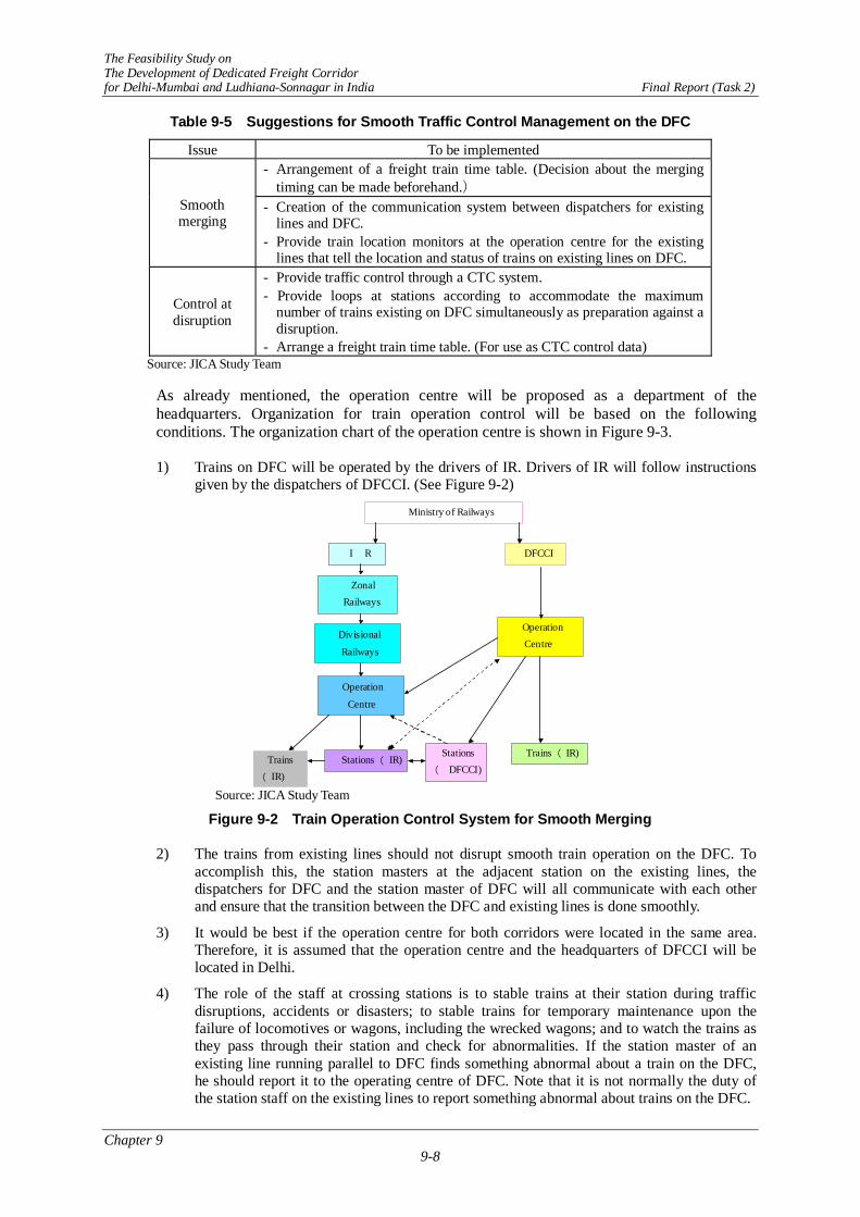
The Feasibility Study on The Development of Dedicated Freight Corridor for Delhi-Mumbai and Ludhiana-Sonnagar in India Final Report (Task 2)
Chapter 9 9-8
Table 9-5 Suggestions for Smooth Traffic Control Management on the DFC
Issue To be implemented - Arrangement of a freight train time table. (Decision about the merging
timing can be made beforehand.) Smooth merging
- Creation of the communication system between dispatchers for existing lines and DFC.
- Provide train location monitors at the operation centre for the existing lines that tell the location and status of trains on existing lines on DFC.
Control at disruption
- Provide traffic control through a CTC system. - Provide loops at stations according to accommodate the maximum
number of trains existing on DFC simultaneously as preparation against a disruption.
- Arrange a freight train time table. (For use as CTC control data) Source: JICA Study Team
As already mentioned, the operation centre will be proposed as a department of the headquarters. Organization for train operation control will be based on the following conditions. The organization chart of the operation centre is shown in Figure 9-3.
1) Trains on DFC will be operated by the drivers of IR. Drivers of IR will follow instructions given by the dispatchers of DFCCI. (See Figure 9-2)
I R DFCCI
Zonal Railways
Divisional
Railways
Operation Centre
Operation
Centre
Stations
( DFCCI)Trains ( IR)
Stations ( IR)Trains
( IR)
Ministry of Railways
Source: JICA Study Team
Figure 9-2 Train Operation Control System for Smooth Merging
2) The trains from existing lines should not disrupt smooth train operation on the DFC. To accomplish this, the station masters at the adjacent station on the existing lines, the dispatchers for DFC and the station master of DFC will all communicate with each other and ensure that the transition between the DFC and existing lines is done smoothly.
3) It would be best if the operation centre for both corridors were located in the same area. Therefore, it is assumed that the operation centre and the headquarters of DFCCI will be located in Delhi.
4) The role of the staff at crossing stations is to stable trains at their station during traffic disruptions, accidents or disasters; to stable trains for temporary maintenance upon the failure of locomotives or wagons, including the wrecked wagons; and to watch the trains as they pass through their station and check for abnormalities. If the station master of an existing line running parallel to DFC finds something abnormal about a train on the DFC, he should report it to the operating centre of DFC. Note that it is not normally the duty of the station staff on the existing lines to report something abnormal about trains on the DFC.

The Feasibility Study on The Development of Dedicated Freight Corridor for Delhi-Mumbai and Ludhiana-Sonnagar in India Final Report (Task 2)
Chapter 9 9-9
SCADA System
Computerized Traffic System
Dispatcher (Electricity)
Dispatchers(Traffic & Freight)
Dispatcher (Signal & Teleco m)
Dispatcher (Track)
Dispatcher (Rolling stock)
SCADA System
Computerized Traffic System
Dispatcher (Electricity)
Dispatchers(Traffic & Freight)
Dispatcher (Signal & Teleco m)
Dispatcher (Track)
Dispatcher (Rolling stock)
Western Corridor Eastern Corridor
DFC Operation Center
Source: JICA Study Team
Figure 9-3 Organization Chart for the Operation Centre
9.5.3 Train operation
(1) Introduction of one-man operation on the DFC and abolition of brake van on the existing line
Normally trains are operated with a driver and a guard. DFC is newly constructed line and has the ability to implement one-man operation, which has been used for 20 years in Japan. (See Figure 9-4)
In Japan, the assistant driver for the train operation on double-track sections was abolished thirty years ago. A guard for the freight train operation was abolished twenty years ago when the one man operation of freight trains was introduced. Incidentally, in Japan operating a train without a brake van was introduced before the riding of the guard on the freight train was abolished. At that time, the guard rode at the back cabin of the locomotive.
DFC is planned so that it will be without level crossings along the way in order to enhance safety. It is possible that the conditions are right for the one-man operation of freight trains on the DFC. It also appears that the conditions are being prepared that will lead to the abolishment of the brake van on existing lines.

The Feasibility Study on The Development of Dedicated Freight Corridor for Delhi-Mumbai and Ludhiana-Sonnagar in India Final Report (Task 2)
Chapter 9 9-10
Figure 9-4 Container Wagons with Reflective Red Circle Substituted for the Brake Van (Japan)
The logic for the one-man operation and abolition of brake van is as follows.
1) Most of operations of the assistant driver were eliminated when the steam locomotives were taken out of service.
When the railway was first introduced, all the trains were hauled by steam locomotives and the assistant driver served as a fireman at that time. With introduction of diesel locomotives and electric locomotives, the work of the fireman was eliminated and many of his other duties were mechanized. In recent years, the job of the assistant driver has been to substitute for the regular driver if he is unable to operate the train because of illness or other reasons.
2) The need for a guard at the tail of the train has been eliminated
At the time when the signal and brake system on trains were poor, a guard rode on the brake van at the tail of the train. He had the important role of preventing accidents. If the train separated, he stopped the disconnected section of the train by winding the hand brake on the brake van. If the train stopped between stations, it was also his job to send a signal to the succeeding train so that it could stop in time.
In the old days when the signals were not working, there was an operation rule called the “time interval block system” that allowed the station master to start the succeeding train after a given interval. In recent years, signal systems have been improved. The time interval blocking system in operation rule is no longer used and abolished. Now there is no fear that the station master behind will not start the succeeding train before arrival of the preceding train at the station. Trains are now equipped with automatic air brakes. When train separation happens, the automatic air brake will activate to stop both train sets automatically. (See Figure 9-5). So a guard is not required on the brake van on trains with automatic brakes. He is only needed on trains with vacuum brakes.

The Feasibility Study on The Development of Dedicated Freight Corridor for Delhi-Mumbai and Ludhiana-Sonnagar in India Final Report (Task 2)
Chapter 9 9-11
Precondition of the General Rule for brake van
Guard will detect it
Automatically stopped by automatic brake system
Driver will detect it
Time interval blocking is allowed
No train can proceed over the s ignal without line c lear
Current conditionNo need of brake van
Source: JICA Study Team
Figure 9-5 The Elimination of the Brake Van
3) When one-man operation is introduced, safety equipments should be facilitated to prevent secondary accidents.
As was mentioned above, the assistant driver has at present to substitute for the regular driver when he can no longer do his job, such as when he is ill or incapacitated. The following are specific examples when the assistant driver can substitute for the regular driver to ensure the safe operation of the train.
- When the driver cannot stop the train by himself.
- When the driver cannot take actions for preventing a secondary accident when his train has derailed and has encroached an adjacent line.
For these cases, safety can be maintained by using the safety equipment installed on the locomotives. But if there were no derailment, the action for preventing the secondary accident would not be required. Reducing the potential for derailment is even more important.
(2) Instruction and training
To enhance the safety of railways, not only introduction of facilities but also instruction and repeated training are important. This is especially true for the drivers of the locomotives. Their role is directly related to safety. The system and program for the instruction and training for the drivers on the DFC should be well organized and take the following features of DFC into consideration.
- One man operation will be carried out, which makes the drivers’ role even more important.
- Traffic on DFC will be controlled with centralized traffic control system. At present orders from dispatchers are given to the drivers by the station master. But on the DFC, train control will be directly carried out through the communication between the dispatchers and drivers. It is clear that the drivers’ role will become even more important. (See Figure 9-6)
- Drivers on DFC are employees of IR and will operate the locomotives according to the General Rules of DFCCIL. In some cases, drivers will have to master two sets of rules: the General Rules of IR and of the rules of the DFCCIL.

The Feasibility Study on The Development of Dedicated Freight Corridor for Delhi-Mumbai and Ludhiana-Sonnagar in India Final Report (Task 2)
Chapter 9 9-12
Current Train Operation System
Station master
Station master
Dispatcher
Train Driver
Train operation System With CTC
Report & Order
Order
Dispatcher
Train Driver
Station Master
Communicate & Order
Source: JICA Study Team
Figure 9-6 Train Operation System with Introduction of CTC
9.5.4 Maintenance
The key concepts to be kept in mind when creating the framework for maintenance are: to reduce the potential for trouble or failure and to reduce the effect of trouble or failure if it does occur. Table 9-6 shows issues that are faced when providing maintenance for the DFC and the measures that should be taken to address these issues.
Table 9-6 Measures for Resolving Issues Facing Maintenance of DFC
Issue Measures for resolving issue
Reducing the number of failures.
- Allocate large-scale maintenance machines at the maintenance depots every 300-400 km along DFC.
- Arrange a freight train time table that clearly show the maintenance block.
- Provide the proper budget for facility maintenance and renewal.
Reacting to incidents and disruptions.
- Allocate maintenance depots in consideration of their capability to deal with incidents and disruptions.
(Allocate branch offices for track maintenance depots every 100 km along the DFC.)
- Allocate a staff at intermediate stations that has received training in how to respond to for incidents or failure of the signals or rolling stock. (This staff will also perform the regular station work.)
- Provide the capability to deal with accidents or disasters with backup dispatch from the depots of the existing lines adjacent to DFC
Source: JICA Study Team
DFC will be constructed with state-of-the-art technology to reduce its total life cycle cost. This means that from the start, the DFC will be a railway that requires less maintenance and will experience fewer problems. Of course, the proper maintenance must still be carried out.
The remaining issue is to provide the capability to deal with the accidents or disasters. The maintenance depots will be allocated in consideration of their ability to respond to accidents. Consideration of the stage-wise implementation these will be necessary. It would be expected that IR would increase its work capacity at the engine sheds, wagon sheds, workshops and depots for the rolling stock it owns.
These ideas above are shown more clearly in Table 9-7.

The Feasibility Study on The Development of Dedicated Freight Corridor for Delhi-Mumbai and Ludhiana-Sonnagar in India Final Report (Task 2)
Chapter 9 9-13
Table 9-7 The Proposed Standard for the Allocation of the Maintenance Depots
Fields Standard of allocation Remarks Track and facility depot
- Branch office at every 100 km.
Power supply depot
- Branch office at every 100km.
DFC
CIL
Signal and tele- communication depot
- Should be allocated every 300-400km.
- Big maintenance machinery should be provided at the maintenance depots.
- Branch office at every 100km Due consideration to the maintenance of
the equipment at the operation centre should be given.
- As for the temporary maintenance, staff with signal maintenance skills should be allocated at each station. (Engaged in station works daily)
Engine depots
- Should be allocated at the station where the locomotive scheduling from JNP and Gujarat can be optimized on the Western corridor.
- Should be allocated at the turn back station of the feeder line on the Eastern corridor.
Indi
an R
ailw
ays
Wagon depots
- Should be allocated at the turn back station of the feeder line on both corridors.
- Spare wagons should be stabled in the yards for departure/arrival.
- Daily inspection site for rolling stock should be allocated at the turn back stations (in most cases this would be on the feeder lines).
- As for the temporary maintenance on the incidents or failures, one or more staff with rolling stock engineering skill should be allocated at every station. (They will also be expected to perform regular station work.)
Source: JICA Study Team 9.6 REVENUE AND EXPENDITURE OF DFC
9.6.1 Standard for the allocation of staff on the DFC
The DFC will have a lean staff allocation in comparison to that of IR. The following section proposes staff allocations based on experience in Japan, as shown in Table 9-1, and the KonKan railways in India, as shown in Table 9-4. When there were no proper figures available for the Konkan Railways, the standard was estimated based on the Japanese railways after making adjustments in consideration of the characteristics of railways in India. The standard of staff allocation of DFC will be proposed as is shown in the Table 9-8.
Incidentally, the average wage of IR 158,419 Rs. will be used as the unit cost for wages

The Feasibility Study on The Development of Dedicated Freight Corridor for Delhi-Mumbai and Ludhiana-Sonnagar in India Final Report (Task 2)
Chapter 9 9-14
Table 9-8 Staff Numbers per Unit for DFC
Site Calculation of staff allocation Unit KRCL JR DFC
Headquarters The route alignment of KRCL with its slim line shape is similar to that of the DFC. The unit figure from KRCL will be used.
Staff per route length
0.52 0.66 0.52
Station staff
At DFC stations, a commercial staff is not required so the staff numbers per station at KRCL cannot be used. So the concept of KRCL and created the following standards is referred. Crossing stations: 3 staff members per shift. Junction stations: 10 staff members per shift. One shift requires 3.5 staff members.
Staff per station
24.9 5.6 16.3 Junction st. 35 Crossing st. 10.5
Drivers
Through operation from IR is carried out. A time table and one man operation will be introduced to the DFC so the figure from Japan can be used.
Staff per 100 train km per day
1.42 1.0 1.0
Track and structures
Primarily based on the unit figures of KRCL. As DFC has double track, the unit figures for maintenance workers will increase by 50% (The figures for watchmen will be the same as that on a single line). Other part will be the same as that of KRCL.
Staff per route length
2.0 Inspection 0.45 Structures 0.3
0.64 2.6
Electrical facilities
KRCL is not electrified so the figures of KRCL cannot be used. An estimate was made by multiplying the maintenance staff for track and structures of DFC with the staff ratio between the track and electric departments in JR group.
Staff per route length
0.23 0.42 1.7
Mai
nten
ance
Rolling stock
KRCL does not have rolling stock depots and the figures of KRCL cannot be adopted. So figures from Japan were used. As the locomotives will be made in Japan, the unit figures for maintaining the locomotives should be the same as in Japan. The requirements for wagon maintenance was deduced by multiplying the unit figures in Japan with the ratio of the number of wagons per train in Japan (26 wagons per train) and that in India (45 wagons per train). The unit figure for wagons in Japan was deduced by the ratio of locomotives per wagon in India (0.45).
Staff per 100 train km per day
2.52 0.65 0.98
Sources IR: Annual Statistical Statements 2004-05 KRCL: Refer to Table 9.4.1 JR: Refer to Table 9.3.1 9.6.2 Expenditures except personnel cost
When we compared the expenditure per train km of IR and that of Konkan railways, we could confirm that the unit expenditure of Konkan railways was less than 80% of that of IR (Table 9-9). Therefore, in general the unit price of expenditure on DFC is assumed to be 80% of that of IR, with the exception of motive power as Konkan railway is not electrified.

The Feasibility Study on The Development of Dedicated Freight Corridor for Delhi-Mumbai and Ludhiana-Sonnagar in India Final Report (Task 2)
Chapter 9 9-15
Table 9-9 Unit Price of Expenditures Other than Personnel Cost
Site Unit price (Rs.) Unit
Headquarters 258,633.6 Per route length Include the cost of railway police
Station 4,644,000.0 Per route length Drivers 2.1 Per train km Motive power (EL) 94.8 Per train km Track and structures 11.5 Per route length Electrical 14.2 Per route length Rolling stock 38.3 Per train km
Source: IR Annual Statistical Statement 2004-05 9.6.3 Tariff
The traffic revenue of DFC was estimated from the tariff level of IR (See Table 9-10) and the estimated traffic volume in ton-km. Considering the transport of the empty wagons or container, unit tariff of containers is assumed to be 0.85 of that in the calculation of the revenue.
Table 9-10 Tariff per Ton-km by Commodity
Commodity /km -300 300-700 700-1000 1000-1500 -1500 Class Coal 0.77 0.77 0.77 0.77 0.56 140 Ore 0.77 0.77 0.77 0.77 0.56 140 Steel 0.77 0.77 0.77 0.77 0.56 140 Food grains 0.6 0.6 0.6 0.6 0.44 110 POL 1.21 1.21 1.21 1.21 0.88 220 Fertilizer 0.6 0.6 0.6 0.6 0.44 110 Cement 0.77 0.77 0.77 0.77 0.77 140 Others 0.77 0.77 0.77 0.77 0.77 Container 7.9 7.4 7.2 7.1 7 TEU
Based on the data of IR website and notifications from IR for Containers(14.Oct.2004) Unit: ton-km, Container: 1TEU-km Tariff for empty container could be reduced to 65 % of normal tariff on the condition that wagons are owned by CONCOR. Tariff for empty wagon could be reduced to 60% of normal tariff in condition that wagons are owned by CONCOR. 9.6.4 Unit price of the expenditure on the existing line
The unit price for freight on the existing line is required in order to calculate of the increase of the benefits and costs relevant to the DFC project. The unit price of the expenditure on the existing section of IR was calculated as 0.348051Rs/train-km from the actual results of IR. (See Table 9-11)
Table 9-11 Unit Price of Freight and the Basis for the Calculation
Terms Figure Unit Expenditure of all IR 427.6 B Rs
Passenger 517.4 M km Train km Freight 283.0 M km
Freight ton-km of all IR 407,398 M ton-km The unit price for freight (Includes personnel cost. Depreciation cost is not included)
0.348051 Rs/ton-km
Source:IR Year Book 2004-05
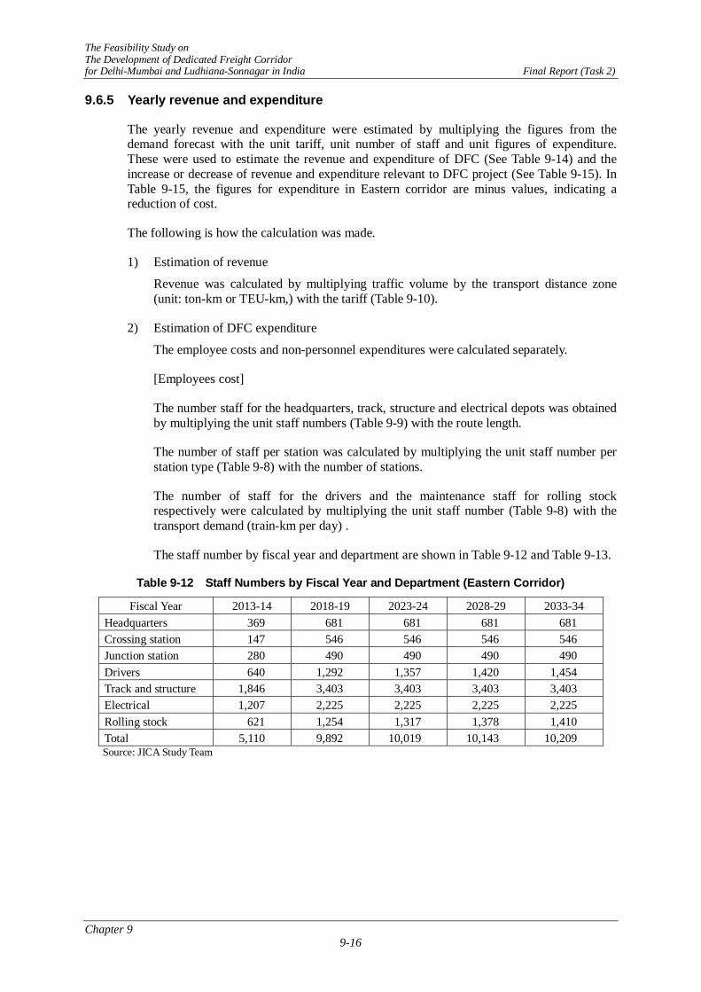
The Feasibility Study on The Development of Dedicated Freight Corridor for Delhi-Mumbai and Ludhiana-Sonnagar in India Final Report (Task 2)
Chapter 9 9-16
9.6.5 Yearly revenue and expenditure
The yearly revenue and expenditure were estimated by multiplying the figures from the demand forecast with the unit tariff, unit number of staff and unit figures of expenditure. These were used to estimate the revenue and expenditure of DFC (See Table 9-14) and the increase or decrease of revenue and expenditure relevant to DFC project (See Table 9-15). In Table 9-15, the figures for expenditure in Eastern corridor are minus values, indicating a reduction of cost.
The following is how the calculation was made.
1) Estimation of revenue
Revenue was calculated by multiplying traffic volume by the transport distance zone (unit: ton-km or TEU-km,) with the tariff (Table 9-10).
2) Estimation of DFC expenditure
The employee costs and non-personnel expenditures were calculated separately.
[Employees cost]
The number staff for the headquarters, track, structure and electrical depots was obtained by multiplying the unit staff numbers (Table 9-9) with the route length.
The number of staff per station was calculated by multiplying the unit staff number per station type (Table 9-8) with the number of stations.
The number of staff for the drivers and the maintenance staff for rolling stock respectively were calculated by multiplying the unit staff number (Table 9-8) with the transport demand (train-km per day) .
The staff number by fiscal year and department are shown in Table 9-12 and Table 9-13.
Table 9-12 Staff Numbers by Fiscal Year and Department (Eastern Corridor)
Fiscal Year 2013-14 2018-19 2023-24 2028-29 2033-34 Headquarters 369 681 681 681 681 Crossing station 147 546 546 546 546 Junction station 280 490 490 490 490 Drivers 640 1,292 1,357 1,420 1,454 Track and structure 1,846 3,403 3,403 3,403 3,403 Electrical 1,207 2,225 2,225 2,225 2,225 Rolling stock 621 1,254 1,317 1,378 1,410 Total 5,110 9,892 10,019 10,143 10,209
Source: JICA Study Team

The Feasibility Study on The Development of Dedicated Freight Corridor for Delhi-Mumbai and Ludhiana-Sonnagar in India Final Report (Task 2)
Chapter 9 9-17
Table 9-13 Staff Numbers by Fiscal Year and Department (Western Corridor)
Fiscal Year 2013-14 2018-19 2023-24 2028-29 2033-34 Headquarters 477 763 763 763 763 Crossing station 231 336 336 336 336 Junction station 245 455 455 455 455 Drivers 844 2,039 2,819 3,584 4,059 Track and structure 2,387 3,817 3,817 3,817 3,817 Electrical 1,561 2,496 2,496 2,496 2,496 Rolling stock 819 1,978 2,736 3,478 3,939 Total 6,565 11,884 13,422 14,928 15,865
Source: JICA Study Team
Employees cost is calculated by multiplying the number of staff with the average wages of IR, namely 158,419Rs.
[Non-personnel expenditure]
For the headquarters, the expenditures were calculated by multiplying unit expenditure (Table 9-9) with the route length.
For stations, the expenditure for each station type was calculated respectively by multiplying the unit expenditure per station type (Table 9-9) with the number of stations.
The expenditure for each depot was calculated respectively for drivers’ office, track and structure depot, electrical depot and rolling stock depot by multiplying the unit expenditure of each depot (Table 9-9) with transport demand (train km).
3) Calculation of expenditure on the existing line of IR
The total expenditure was calculated by multiplying the unit expenditure (Table 9-11) with transport demand (ton-km). Note that this expenditure includes personnel expenses.
Table 9-14 Revenue and Expenditure of DFC
Unit: MRs
Items 2013-14 2018-19 2023-24 2028-29 2033-34
Revenue 26,271.3 51,846.0 53,965.9 55,969.5 57,073.0
Easte
rn
Cor
ridor
Expenditure 4,155.0 8,390.0 8,720.0 9,040.0 9,211.0
Revenue 16,685.7 37,301.1 50,196.2 62,874.8 70,762.3
Wes
tern
C
orrid
or
Expenditure 5,449.0 12,217.0 16,193.0 20,086.0 22,506.0
Revenue 42,957.1 89,147.1 104,162.1 118,844.3 127,835.3
Tota
l
Expenditure 9,604.0 20,607.0 24,913.0 29,126.0 31,717.0
Source: JICA Study Team Note : The amounts indicated above are amount before deduction of interest and depreciation.

The Feasibility Study on The Development of Dedicated Freight Corridor for Delhi-Mumbai and Ludhiana-Sonnagar in India Final Report (Task 2)
Chapter 9 9-18
Table 9-15 Increase of Revenue and Expenditure Relevant to the Project
Unit: MRs Items 2013-14 2018-19 2023-24 2028-29 2033-34
Increase of revenue 14,708.8 26,202.3 31,129.8 37,162.1 40,249.7
Onl
y Ea
stern
C
orrid
or
Increase of expenditure -1,418.4 -4,517.5 -2,902.6 -423.4 759.9
Increase of revenue 11,652.1 26,724.1 44,204.3 60,166.1 70,013.8
Onl
y W
este
rn
Cor
ridor
Increase of expenditure 1,340.0 4,357.6 11,030.6 16,976.5 20,595.4
Increase of revenue 15,141.1 41,693.1 62,133.0 80,955.3 92,101.6
Bot
h C
orrid
ors
Increase of expenditure -4,362.2 -3,461.2 4,545.2 11,944.2 16,229.2
Source: JICA Study Team Note: The amounts indicated above are amount before deduction of interest and depreciation.
9.6.6 Evaluation
The revenue and cost of the DFC appears to be favourable from the start of operation. The management structure also seems favourable. Please note that these figures are before the payment of interest and depreciation. The Eastern Corridor is more profitable than the Western Corridor because coal is the major commodity transported on the Eastern Corridor. The transport volume of tonnage per train in bulk is bigger than that of a container train, so the expenditure will increase according to the train-km.
As for the increase of the revenue and expenditure relevant to the project, the total figure is favourable at every time point. These figures are less than that of DFC. It is believed that this is because it has been set off by the transferred volume from the existing line of the IR to the DFC. As these figures are before payment of interest and depreciation, the final evaluation will be left to the financial evaluation.