Embed Size (px)
Citation preview
National Fire Protection Association 1 Batterymarch Park, Quincy, MA 02169-7471 Phone: 617-770-3000 • Fax: 617-770-0700 • www.nfpa.org
M E M O R A N D U M TO: NFPA Technical Committee on Water Mist Fire Suppression Systems FROM: Elena Carroll, Administrator, Technical Projects DATE: August 29, 2012 SUBJECT: NFPA 750 First Draft Letter Ballot (F2013)
______________________________________________________________________ Please find the attached the First Revisions for NFPA 750. The ballot is for formally voting on whether or not you concur with the committee’s First Revisions. Reasons must accompany all negative and abstaining votes. Please do not vote negatively because of editorial errors. However, please bring such errors to my attention for action. Please complete and return your ballot as soon as possible but no later than August 31, 2012. As noted on the ballot form, please return the ballot to Elena Carroll either via e-mail to [email protected] or via fax to 617-984-7110. You may also mail your ballot to the attention of Elena Carroll at NFPA, 1 Batterymarch Park, Quincy, MA 02169. The return of ballots is required, by the Regulations Governing the Development of NFPA Standards.
Report on First Revision – November 2013 NFPA 750_______________________________________________________________________________________________750 FR1 Final Action:(Chapter 2)_______________________________________________________________________________________________Submitter: Technical Committee Water Mist Fire Suppression SystemsRecommendation: Update the following references:Chapter 2 Referenced Publications2.1 General. The documents or portions thereof listed in this chapter are referenced within this standard and shall beconsidered part of the requirements of this document.2.2 NFPA Publications. National Fire Protection Association, 1 Batterymarch Park, Quincy, MA 02169-7471.NFPA 13, Standard for the Installation of Sprinkler Systems, 2010 edition.NFPA 20, Standard for the Installation of Stationary Pumps for Fire Protection, 2010 edition.NFPA 22, Standard for Water Tanks for Private Fire Protection, 2008 edition.NFPA 25, Standard for the Inspection, Testing, and Maintenance of Water-Based Fire Protection Systems, 20112008edition.NFPA 70®, National Electrical Code®, 20082011 edition.NFPA 72®, National Fire Alarm and Signaling Code, 2010 edition.NFPA 170, Standard for Fire Safety and Emergency Symbols, 2009 2012 edition.2.3 Other Publications.2.3.1 ANSI Publications. American National Standards Institute, Inc., 25 West 43rd Street, 4th Floor, New York, NY10036.ANSI B1.20.1, Pipe Threads, General Purpose (Inch), 1992.ANSI B16.18, Cast Copper Alloy Solder Joint Pressure Fittings, 1994.ANSI B16.22, Wrought Copper and Copper Alloy Solder Joint Pressure Fittings, 1995.ANSI B16.18, Cast Copper AlloySolder Joint Pressure Fittings, 1994.ANSI B16.22, Wrought Copper and Copper Alloy Solder Joint Pressure Fittings,19952.3.21 ASME Publications. American Society of Mechanical Engineers, Three Park Avenue, New York, NY10016-5990.ASME Boiler and Pressure Vessel Code, 20010.ANSI/ASME B1.20.1, Pipe Threads, General Purpose (Inch), 2006.ASME B16.18, Cast Copper Alloy Solder Joint Pressure Fittings, 2012.ASME B16.22, Wrought Copper and Copper Alloy Solder Joint Pressure Fittings, 2005.ASME B31.1, Power Piping Code, 19982010.2.3.32 ASTM Publications. ASTM International, 100 Barr Harbor Drive, P. O. Box C700, West Conshohocken, PA19428-2959.ASTM A 269, Standard Specification for Seamless and Welded Austenitic Stainless Steel Tubing for General Service,20010.ASTM A 351/ASTM A 351M, Standard Specification for Castings, Austenitic, Austenitic-Ferritic (Duplex) forPressure-Containing Parts, 200010.ASTM A 403/ASTM A 403M, Standard Specification for Wrought Austenitic Stainless Steel Piping Fittings, 20002011.ASTM A 632, Standard Specification for Seamless and Welded Austenitic Stainless Steel Tubing (Small-Diameter) forGeneral Service, 19902009.ASTM A 774/ASTM A 774M, Standard Specification for As-Welded Wrought Austenitic Stainless Steel Fittings forGeneral Corrosive Service at Low and Moderate Temperatures, 20009.ASTM A 778, Standard Specification for Welded, Unannealed Austenitic Stainless Steel Tubular Products, 20009.ASTM A 789/ASTM A 789M, Standard Specification for Seamless and Welded Ferritic/Austenitic Stainless Steel Tubingfor General Service, 19952010.ASTM A 815/ASTM A 815M, Standard Specification for Wrought Ferritic, Ferritic/Austenitic, and Martensitic StainlessSteel Piping Fittings, 19982010.ASTM B 32, Standard Specification for Solder Metal, 20008.ASTM B 42, Standard Specification for Seamless Copper Pipe, Standard Sizes, 19982010.ASTM B 75/ B 75M, Standard Specification for Seamless Copper Tube, 20111999.ASTM B 88, Standard Specification for Seamless Copper Water Tube, 19992009.ASTM B 251, Standard Specification for General Requirements for Wrought Seamless Copper and Copper-Alloy Tube,19972010.ASTM B 813, Standard Specification for Liquid and Paste Fluxes for Soldering Applications of Copper and Copper-AlloyTube, 20002010.
1Printed on 8/29/2012
Report on First Revision – November 2013 NFPA 7502.3.43 AWS Publications. American Welding Society, 550 N.W. LeJeune Road, Miami, FL 33126.AWS A5.8M/ A5.8, Specification for Filler Metals for Brazing and Braze Welding, 19922011.AWS D10.9, Specification for Qualification of Welding Procedures and Welders for Piping and Tubing, 1980.2.3.54 IMO Publications. International Maritime Organization, 4 Albert Embankment, London, SEI 7SR, UnitedKingdom.IMO Assembly Resolution A.800(19), Revised Guidelines for Approval of Sprinkler Systems.IMO Code for Application of Fire Test Procedures, 1998.IMO MSC/Circ. 668, Alternative Arrangements for Halon Fire-Extinguishing Systems in Machinery Spaces andPumprooms.IMO MSC/Circ. 728, Revised Test Method for Equivalent Water-Based Fire-Extinguishing Systems for MachinerySpaces of Category A and Cargo Pump-Rooms Contained in MSC/Circ. 668.IMO MSC/Circ. 913, Guidelines for the Approval of Fixed Water-Based Local Application Fire-Fighting Systems for Usein Category A Machinery Spaces, 1999.SOLAS Regulation 11-2/12.4.1, Consolidated Edition, 20091992.2.3.65 ISO Publications. International Organization for Standardization, 1 rue de Varembé, Case postale 56, CH-1211Geneve 20, Switzerland.ISO 1219-1, Fluid power systems and components — Graphic symbols and circuit diagrams — Part 1: Graphicsymbols, 19912006.ISO 1219-2, Fluid power systems and components — Graphic symbols and circuit diagrams — Part 2: Circuit diagrams,1995.2.3.76 ULC Publications. Underwriters' Laboratories of Canada, 7 Underwriters Road, Toronto, Ontario M1R 3B4,Canada.CAN/ULC S524-06, Standard for the Installation of Fire Alarm Systems, 2006.CAN/ULC S529-02, Standard for Smoke Detectors for Fire Alarm Systems, 2002.2.3.87 U.S. Coast Guard Publication. 2100 Second Street, S.W., Washington, DC 20593-0001.NVIC 9-97, Guide to Structural Fire Protection, 19972011.2.3.98 U.S. Government Publication. U.S. Government Printing Office, Washington, DC 20402.Title 46, Code of Federal Regulations, Parts 56.50 and 56.75, “Shipping.”Title 49, Code of Federal Regulations, “Transportation.”2.3.109 Other Publications.EN-13480-3, Metallic Industrial Piping Code, Design and Calculation, 2002.Merriam-Webster's Collegiate Dictionary, 11th edition, Merriam-Webster, Inc., Springfield, MA, 2003.2.4 References for Extracts in Mandatory Sections.NFPA 25, Standard for the Inspection, Testing, and Maintenance of Water-Based Fire Protection Systems, 2008 2011edition.
_______________________________________________________________________________________________750 FR54 Final Action:(3.3.1 Acceptance Test Plan (New) )_______________________________________________________________________________________________Submitter: Technical Committee Water Mist Fire Suppression SystemsRecommendation: Add new definition as shown:
3.3.1 Acceptance Test Plan. A complete step-by-step description of the proposed acceptance test procedure thatidentifies all devices, controls, and functions to be tested and how the test will be conducted.
2Printed on 8/29/2012
Report on First Revision – November 2013 NFPA 750_______________________________________________________________________________________________750 FR119 Final Action:(3.3.3 Deluge System)_______________________________________________________________________________________________Submitter: Technical Committee Water Mist Fire Suppression SystemsRecommendation: 3.3.3 Deluge System. A water mist system using open nozzles attached to a piping system that isconnected to a water supply through a valve that is opened by means of a detection system installed in the same areaas the mist nozzles. When the valve opens, water flows into the piping system and discharges through all nozzlesattached to the system.
_______________________________________________________________________________________________750 FR13 Final Action:(3.3.13 Pressure)_______________________________________________________________________________________________Submitter: Technical Committee Water Mist Fire Suppression SystemsRecommendation: Revise text to read as follows:3.3.13 Pressure.3.3.13.1 Nozzle Operating Pressure. The pressure range at which nozzles are listed to control, suppress or extinguisha fire.3.3.13.2 Standby Pressure. The pressure that exists in the distribution system in the static state, prior to nozzledischarge.3.3.13.3 System Design Pressure. The maximum pressure a system or component is rated to withstand.3.3.2313.4 Working Pressure. The maximum anticipated static (nonflowing) or pressure applied to the systemcomponents exclusive of surge pressures.
_______________________________________________________________________________________________750 FR67 Final Action:(3.3.14 Pressure Relief Device (New) )_______________________________________________________________________________________________Submitter: Technical Committee Water Mist Fire Suppression SystemsRecommendation: Add new text to read as follows:3.3.14 Pressure Relief Device. A device designed for the purpose of preventing pressure levels in excess of thedesign pressure of the system, the system components, or both.
_______________________________________________________________________________________________750 FR4 Final Action:(3.3.15 Pressure-Regulating Valve (New) )_______________________________________________________________________________________________Submitter: Technical Committee Water Mist Fire Suppression SystemsRecommendation: Add new text to read as follows:3.3.15 Pressure-Regulating Valve. A valve designed for the purpose of reducing,regulating, controlling, or restrictingwater pressure.
_______________________________________________________________________________________________750 FR120 Final Action:(3.3.17 Total Compartment Application System)_______________________________________________________________________________________________Submitter: Technical Committee Water Mist Fire Suppression SystemsRecommendation: 3.3.17 Total Compartment Application System. A system designed to discharge water mist toprotect all hazards in an enclosure.
3Printed on 8/29/2012
Report on First Revision – November 2013 NFPA 750_______________________________________________________________________________________________750 FR7 Final Action:(3.3.20 Twin-Fluid System)_______________________________________________________________________________________________Submitter: Technical Committee Water Mist Fire Suppression SystemsRecommendation: Revise existing definition of Twin-fluid System as follows:
3.3.1820 Twin–Fluid System. A water mist system in which water and an atomizing media medium are separatelysupplied to and mixed at the water mist nozzle the water mist nozzle utilizing a separate piping system for each mediumor a single piping system for both.
_______________________________________________________________________________________________750 FR68 Final Action:(3.3.21 Unloader Valve (New) )_______________________________________________________________________________________________Submitter: Technical Committee Water Mist Fire Suppression SystemsRecommendation: Add new text to read as follows:3.3.21 Unloader Valve. A valve that is designed to relieve excess flow below pump capacity at set pump pressure. [20,2013]
_______________________________________________________________________________________________750 FR90 Final Action:(3.3.22 Water Mist)_______________________________________________________________________________________________Submitter: Technical Committee Water Mist Fire Suppression SystemsRecommendation: Revise existing section as follows:3.3.1922* Water Mist. A water spray for which the Dv0.99 for the flow-weighted cumulative volumetric distribution of waterdroplets is less than 1000 microns µm at the within the nozzle operating pressure range minimum design operatingpressure of the water mist nozzle.
_______________________________________________________________________________________________750 FR8 Final Action:(3.3.23.2 Multi-functional Water Mist Nozzles)_______________________________________________________________________________________________Submitter: Technical Committee Water Mist Fire Suppression SystemsRecommendation: Revise text to read as follows:3.3.2123.2 Hybrid Multi-functional Water Mist Nozzles. Nozzles capable of operation using both automatic andnonautomatic means.
_______________________________________________________________________________________________750 FR121 Final Action:(3.3.24 Zoned Application System)_______________________________________________________________________________________________Submitter: Technical Committee Water Mist Fire Suppression SystemsRecommendation: 3.3.24 Zoned Application System. A system designed to protect hazards in a predeterminedportion of an enclosure.
4Printed on 8/29/2012
Report on First Revision – November 2013 NFPA 750_______________________________________________________________________________________________750 FR9 Final Action:(3.3.24.1 Automatic Sprinkler Alternative Water Mist Systems (New) )_______________________________________________________________________________________________Submitter: Technical Committee Water Mist Fire Suppression SystemsRecommendation: Add a new definition as follows:3.3.24.1* Automatic Sprinkler Alternative Water Mist Systems. A water mist system utilizing automatic water mistnozzles installed in a building and designed to provide primary fire protection that is an alternative to automatic sprinklersystems.
_______________________________________________________________________________________________750 FR5 Final Action:(3.3.24.2 Deluge Water Mist System (New) )_______________________________________________________________________________________________Submitter: Technical Committee Water Mist Fire Suppression SystemsRecommendation: Add new:3.3.24.2 Deluge Water Mist System. A water mist system utilizing nonautomatic mist nozzles (open) attached to apiping network connected to the fluid supply(ies) through a valve controlled by an independent detection systeminstalled in the same area as the mist nozzles.
_______________________________________________________________________________________________750 FR10 Final Action:(3.3.24.7 Pre-engineered Water Mist Systems)_______________________________________________________________________________________________Submitter: Technical Committee Water Mist Fire Suppression SystemsRecommendation: Revise text to read as follows:3.3.2224.57* Pre-engineered Water Mist Systems. Those systems having predetermined flow rates, nozzlepressures, and water quantities pipe and tube sizes, maximum and minimum pipe lengths, number of fittings andnumbers and types of nozzles, nozzle pressures, atomizing media and water storage quantities, and which do notrequire additional hydraulic calculations.
_______________________________________________________________________________________________750 FR11 Final Action:(3.3.24.8 Total Compartment Application Water Mist System (New) )_______________________________________________________________________________________________Submitter: Technical Committee Water Mist Fire Suppression SystemsRecommendation: Add new text as follows:3.3.24.8 Total Compartment Application Water Mist System. A deluge water mist system that provides completeprotection of an enclosure or space by the simultaneous operation of all nozzles in the space by manual or automaticmeans.
5Printed on 8/29/2012
Report on First Revision – November 2013 NFPA 750_______________________________________________________________________________________________750 FR12 Final Action:(3.3.24.9 Zoned Application Water Mist System (New) )_______________________________________________________________________________________________Submitter: Technical Committee Water Mist Fire Suppression SystemsRecommendation: Add new text as follows:3.3.24.9 Zoned Application Water Mist System. A total compartment application water mist system utilizingnonautomatic nozzles, or intermixed nonautomatic and automatic nozzles, in which the piping network is subdivided intopredetermined zones controlled by individual control valves, and which protects a predetermined portion of thecompartment by the manual or automatic activation of a selected group of nozzles.
6Printed on 8/29/2012
Report on First Revision – November 2013 NFPA 750_______________________________________________________________________________________________750 FR16 Final Action:(Chapter 5 (New))_______________________________________________________________________________________________Submitter: Technical Committee Water Mist Fire Suppression SystemsRecommendation: Add new Chapter 5 as follows:Chapter 5 Classification of Occupancies.5.1* Classification of Occupancies.5.1.1 Occupancy classifications for this standard shall relate to water mist system design, installation, and water supplyrequirements only.5.1.2 Occupancy classifications shall not be intended to be a general classification of occupancy hazards.5.2* Light Hazard Occupancies. Light hazard occupancies shall be defined as occupancies or portions of otheroccupancies where the quantity and/or combustibility of contents is low and fires with relatively low rates of heat releaseare expected.5.3* Ordinary Hazard Occupancies.5.3.1* Ordinary Hazard (Group 1). Ordinary hazard (Group 1) occupancies shall be defined as occupancies or portionsof other occupancies where combustibility is low, quantity of combustibles is moderate, stockpiles of combustibles donot exceed 8 ft (2.4 m), and fires with moderate rates of heat release are expected.5.3.2* Ordinary Hazard (Group 2). Ordinary hazard (Group 2) occupancies shall be defined as occupancies or portionsof other occupancies where the quantity and combustibility of contents are moderate to high, where stockpiles ofcontents with moderate rates of heat release do not exceed 12 ft (3.66 m) and stockpiles of contents with high rates ofheat release do not exceed 8 ft (2.4 m).5.4 Extra Hazard Occupancies.5.4.1* Extra Hazard (Group 1). Extra hazard (Group 1) occupancies shall be defined as occupancies or portions ofother occupancies where the quantity and combustibility of contents are very high and dust, lint, or other materials arepresent, introducing the probability of rapidly developing fires with high rates of heat release but with little or nocombustible or flammable liquids.5.4.2* Extra Hazard (Group 2). Extra hazard (Group 2) occupancies shall be defined as occupancies or portions ofother occupancies with moderate to substantial amounts of flammable or combustible liquids or occupancies whereshielding of combustibles is extensive.5.5* Special Occupancy Requirements. Water mist systems shall be permitted to be used for special occupanciesprovided that they have been listed for such occupancies.5.6 Residential Occupancies.5.6.1 Residential Occupancies up to and Including Four Stories in Height. Residential Occupancies shall include
the following, as defined in NFPA 101®, Life Safety Code:(1) Apartment buildings(2) Lodging and rooming houses(3) Board and care facilities(4) Hotels, motels, and dormitories.5.6.2 One- and Two-Family Dwellings. One- and two-family dwellings shall be defined as any detached building or anypart of a townhouse structure that is separated from the remainder of the townhouse structure with fire resistance ratedassemblies in accordance with local building code; that contains no more than two dwelling units intended to be used,rented, leased, let, or hired out to be occupied; or that is occupied for habitation purposes.
7Printed on 8/29/2012
Report on First Revision – November 2013 NFPA 750_______________________________________________________________________________________________750 FR92 Final Action:(6.1.2)_______________________________________________________________________________________________Submitter: Technical Committee Water Mist Fire Suppression SystemsRecommendation: Revise existing section as follows:56.1.2 Design Pressure Working Pressure.56.1.2.1 System components shall be rated for have a design pressure equal to or greater than the maximum workingpressure to which they are exposed but not less than 12.1 bar (175 psi).56.1.2.2 Where components are part of a listed, pre-engineered system with a self-contained water supply, the pressurerating shall be in accordance with the listing requirements.
_______________________________________________________________________________________________750 FR19 Final Action:(6.2.2.1)_______________________________________________________________________________________________Submitter: Technical Committee Water Mist Fire Suppression SystemsRecommendation: Revise text to read as follows:56.2.2.1* Installation. Gas and water containers shall be designed for installation according to the manufacturer’sinstallation manual, including provision for attachment of seismic restraint where required.
_______________________________________________________________________________________________750 FR20 Final Action:(6.2.2.4)_______________________________________________________________________________________________Submitter: Technical Committee Water Mist Fire Suppression SystemsRecommendation: Revise text to read as follows:
56.2.2.4 Design Pressure. The design pressure shall be based on the maximum pressure developed by the watermist system at 54ºC (130ºF) or a higher temperature as specified in the manufacturer’s listing.
_______________________________________________________________________________________________750 FR21 Final Action:(6.3.1.1)_______________________________________________________________________________________________Submitter: Technical Committee Water Mist Fire Suppression SystemsRecommendation: Revise text to read as follows:56.3.1.1 All wetted surfaces in piping, valves, and fittings from the system strainer to the nozzle, shall have corrosionresistance at least equivalent to that for piping as specified in Table 56.3.3.1.
_______________________________________________________________________________________________750 FR23 Final Action:(6.3.4.1)_______________________________________________________________________________________________Submitter: Technical Committee Water Mist Fire Suppression SystemsRecommendation: Revise text to read as follows:56.3.4.1* Pipe or tube shall be of noncombustible material having physical and chemical characteristics such that itsdeterioration under stress can be predicted with reliability.56.3.4.2* The piping shall be in accordance with ASME B31.1, Power Piping Code or EN13480-3, Metallic IndustrialPiping.
8Printed on 8/29/2012
Report on First Revision – November 2013 NFPA 750_______________________________________________________________________________________________750 FR24 Final Action:(6.3.4.3)_______________________________________________________________________________________________Submitter: Technical Committee Water Mist Fire Suppression SystemsRecommendation: Revise text to read as follows:56.3.4.3 Where using the equations provided in ASME B31.1, Power Piping Code, or EN13480-3, Metallic IndustrialPiping Code, are used to calculate either the maximum working design pressure (Pw) for a specific pipe or tube or theminimum wall thickness (tm) of the pipe or tube for a specific operating working pressure, a steel temperature of 54°C(130°F) or the expected ambient temperature to which the pipe or tube will be exposed, shall be used, whichever isgreater, shall be used.
_______________________________________________________________________________________________750 FR27 Final Action:(6.4.1.2 (New) )_______________________________________________________________________________________________Submitter: Technical Committee Water Mist Fire Suppression SystemsRecommendation: Add new text:6.4.1.2 Welding and brazing alloys shall have a melting point above 538°C (1000°F).
_______________________________________________________________________________________________750 FR26 Final Action:(6.4.1.2.2, 6.4.1.2.3)_______________________________________________________________________________________________Submitter: Technical Committee Water Mist Fire Suppression SystemsRecommendation: Revise text as follows:56.4.1.2.2 A supply of minimum of one spare adapters conversion fitting of each type shall be maintained on thepremises so that any adapters conversion fittings that have been damaged in any way can be promptly replaced.56.4.1.2.3 Adapter Conversion fitting information shall also be maintained on the drawings.
_______________________________________________________________________________________________750 FR94 Final Action:(6.4.3.1, 6.4.3.2)_______________________________________________________________________________________________Submitter: Technical Committee Water Mist Fire Suppression SystemsRecommendation: Revise existing text as follows:56.4.3.1 Fittings shall have a minimum-rated system design working pressure equal to or greater than the maximumoperating working pressure of the water mist systems at 54°C (130°F).56.4.3.2 For systems that employ the use of a pressure regulating device in the distribution piping, the fittingsdownstream of the device shall have a minimum-rated minimum rated system design working pressure equal to orgreater than the maximum anticipated working pressure in the downstream piping.
_______________________________________________________________________________________________750 FR122 Final Action:(6.4.3.5)_______________________________________________________________________________________________Submitter: Technical Committee Water Mist Fire Suppression SystemsRecommendation: 5.4.3.5 Welding and brazing alloys shall have a melting point above 538°C (1000°F).
9Printed on 8/29/2012
Report on First Revision – November 2013 NFPA 750_______________________________________________________________________________________________750 FR28 Final Action:(6.5.2 (New) )_______________________________________________________________________________________________Submitter: Technical Committee Water Mist Fire Suppression SystemsRecommendation: Add new text:6.5.2 Hangers used on low pressure water mist systems shall be permitted to be designed and installed in accordancewith NFPA 13, Standard for the Installation of Sprinkler Systems.
_______________________________________________________________________________________________750 FR95 Final Action:(6.6.1)_______________________________________________________________________________________________Submitter: Technical Committee Water Mist Fire Suppression SystemsRecommendation: Revise existing text as follows:56.6.1* Listing. Nozzles shall be listed either individually or as a part of a pre-engineered system, and the listinginformation shall include the following:(1) Specific hazards and protection objectives(2) Volumetric flow rate characteristics of water discharge for each nozzle(3) Maximum height of protected space(4) Minimum distance between nozzle tip or diffuser, as applicable, and plane of protection(5) Maximum spacing between nozzles(6) Maximum coverage area per nozzle(7) Minimum spacing between nozzles(8) Maximum height between ceiling and nozzle diffuser or tip, as applicable(9) Nozzle obstruction spacing criteria(10) Maximum spacing of nozzles from walls(11) Nozzle operating pressure range Minimum- and maximum-rated operating pressures of nozzles(12) Allowable range of nozzle orientation angle from vertically down(13) Classification of automatic nozzle thermal response characteristics as fast, special, or standard response(14) Maximum compartment volume, if applicable(15) Maximum time delay for water mist delivery to the most remote nozzle
_______________________________________________________________________________________________750 FR96 Final Action:(6.9.1.3.2)_______________________________________________________________________________________________Submitter: Technical Committee Water Mist Fire Suppression SystemsRecommendation: Revise existing section as follows:56.9.1.3.2 Overpressure shall not exceed the design working pressure of the piping system.
_______________________________________________________________________________________________750 FR30 Final Action:(6.9.1.7)_______________________________________________________________________________________________Submitter: Technical Committee Water Mist Fire Suppression SystemsRecommendation: Revise text to read as follows:56.9.1.7 Unloader Valves. Unloader valves shall be part of a listed or approved as part of the pump assembly or belisted separately.
10Printed on 8/29/2012
Report on First Revision – November 2013 NFPA 750_______________________________________________________________________________________________750 FR6 Final Action:(6.9.3.1)_______________________________________________________________________________________________Submitter: Technical Committee Water Mist Fire Suppression SystemsRecommendation: Revise text to read as follows:56.9.3.1 Listing. Controllers for pumps shall be listed fire pump controllers and or listed limited service controllers beinstalled in accordance with NFPA 20, Standard for the Installation of Stationary Pumps for Fire Protection.
_______________________________________________________________________________________________750 FR32 Final Action:(6.10.3.4)_______________________________________________________________________________________________Submitter: Technical Committee Water Mist Fire Suppression SystemsRecommendation: Revise text to read as follows:56.10.3.4 Temperature Limitations. Devices shall be designed to function from a minimum range of 4°C to 54°C (40°Fto 130°F), or devices designed to function outside of this range shall be so indicated −29°C to 54°C (−20°F to 130°F) orshall be marked to indicate temperature limitations.
_______________________________________________________________________________________________750 FR33 Final Action:(6.10.3.6.8 (New) )_______________________________________________________________________________________________Submitter: Technical Committee Water Mist Fire Suppression SystemsRecommendation: Add new text to read as follows:6.10.3.6.8 The requirements of 6.10.3.6 shall not apply to dry and wet pipe systems utilizing individual thermallyactivated nozzles.
_______________________________________________________________________________________________750 FR34 Final Action:(7.1)_______________________________________________________________________________________________Submitter: Technical Committee Water Mist Fire Suppression SystemsRecommendation: Revise text to read as follows:67.1 General. Water mist systems shall be described by the following four five parameters as appropriate:(1) System application(2) Nozzle type(3) System operation method(4) System media type(5) Classification of occupancy
11Printed on 8/29/2012
Report on First Revision – November 2013 NFPA 750_______________________________________________________________________________________________750 FR35 Final Action:(7.2 through 7.2.4.4)_______________________________________________________________________________________________Submitter: Technical Committee Water Mist Fire Suppression SystemsRecommendation: Revise text to read as follows:67.2 System Applications. System applications shall consist of one of the following three four categories:(1) Local-application systems(2) Total compartment application systems(3) Zoned application systems(4) Automatic sprinkler alternative water mist application systems67.2.1 Local-Application Systems.7.2.1.1 Local-application systems shall be designed and installed to provide complete distribution of mist on or aroundthe hazard or object to be protected.67.2.1.12 Local-application systems shall be designed to protect an object or a hazard in an enclosed, unenclosed, oropen outdoor condition.67.2.1.23 Local-application systems shall be actuated by automatic nozzles or by an independent detection system.67.2.2 Total Compartment Application Systems.67.2.2.1 Total compartment application systems are shall be designed and installed to provide complete protection of anenclosure or space.67.2.2.2* The complete protection of an enclosure or space shall be achieved by the simultaneous operation of allnozzles in the space by manual or automatic means.67.2.3* Zoned Application Systems.7.2.3.1 Zoned application systems are a subset of the compartment system and are shall be designed to protect apredetermined portion of the compartment by the activation of a selected group of nozzles.67.2.3.12 Zoned application systems shall be designed and installed to provide complete mist distribution throughout apredetermined portion of an enclosure or space. This shall be achieved by simultaneous operation of a selected groupof nozzles in a predetermined portion of the space by manual or automatic means.67.2.3.23 Zoned application systems shall be actuated by automatic nozzles or by an independent detection system.7.2.4 Automatic Sprinkler Alternative Water Mist Systems.7.2.4.1 Automatic sprinkler alternative water mist systems shall be designed and installed to provide automatic fireprotection throughout a building or area.7.2.4.2 Automatic sprinkler alternative water mist system devices shall be listed for the intended occupancyclassification as described in Chapter 5 unless otherwise permitted in this standard.7.2.4.3 Automatic sprinkler alternative water mist systems shall be of the wet pipe or dry pipe type.7.2.4.4 The requirements of 7.2.4.3. shall not apply where environmental or operational conditions dictate whether thereis a wet or dry system.
_______________________________________________________________________________________________750 FR18 Final Action:(7.3)_______________________________________________________________________________________________Submitter: Technical Committee Water Mist Fire Suppression SystemsRecommendation: 67.3 Nozzle Types. Water mist nozzles shall be classified as one of the following three types:(1) Automatic(2) Nonautomatic(3) Hybrid Multifunctional
12Printed on 8/29/2012
Report on First Revision – November 2013 NFPA 750_______________________________________________________________________________________________750 FR37 Final Action:(7.4.3.3)_______________________________________________________________________________________________Submitter: Technical Committee Water Mist Fire Suppression SystemsRecommendation: Revise existing section as follows:67.4.3.3 The pressurized piping in all preaction systems shall be supervised to ensure system piping integrity.
_______________________________________________________________________________________________750 FR36 Final Action:(7.4.4.3 (New) )_______________________________________________________________________________________________Submitter: Technical Committee Water Mist Fire Suppression SystemsRecommendation: Add new text to read as follows:7.4.4.3 The pressurized piping in all dry pipe systems shall be supervised to ensure system integrity.
_______________________________________________________________________________________________750 FR74 Final Action:(8.1.2)_______________________________________________________________________________________________Submitter: Technical Committee Water Mist Fire Suppression SystemsRecommendation: Revise as follows:78.1.2 System Design and Installation Manual. Materials and devices shall be installed in accordance with themanufacturer’s system design and installation manual.
13Printed on 8/29/2012
Report on First Revision – November 2013 NFPA 750_______________________________________________________________________________________________750 FR38 Final Action:(8.1.6 (New) )_______________________________________________________________________________________________Submitter: Technical Committee Water Mist Fire Suppression SystemsRecommendation: Add new text to read as follows:8.1.6 Automatic Sprinkler Alternative Water Mist Systems.8.1.6.1 Spacing and Location of Nozzles. The requirements for spacing, location, and position of water mist nozzlesshall be based on the following principles:(1) Nozzles shall be installed throughout the premises unless the nozzles are specifically tested and the test resultsdemonstrate that omission of water mist nozzles from certain limited areas is permissible.(2) Nozzles shall be located so as not to exceed the spacing criteria specified by the manufacturer in the system designand installation manual.(3) Nozzles shall be positioned and located so as to provide satisfactory performance with respect to activation time anddistribution pattern.(4) When nozzles are specifically tested and the test results demonstrate that deviations from clearance requirements toobstructions do not impair the ability of the system to control or suppress a fire, their positioning and locating inaccordance with the test results shall be permitted.(5) Clearance between nozzles and ceilings exceeding the maximums specified in the standard or in the manufacturer’ssystem design and installation manual shall be permitted, provided that tests or calculations demonstrate performanceof the automatic water mist nozzles comparable to those installed in conformance with this standard.(6) Furniture, portable wardrobe units, cabinets, trophy cases, and similar objects or features not intended foroccupancy, whether freestanding or attached to the finished structure, do not require nozzles to be installed in them.8.1.6.2 System Protection Area Limitations. The maximum area on any one floor to be protected by water mistsupplied by any one water mist system riser or combined system riser shall be as follows:
(1) Light hazard - 4,831 m2 (52,000 ft2)
(2) Ordinary hazard - 4,831 m2 (52,000 ft2)
(3) Extra hazard - 3,716 m2
(40,000 ft2)
8.1.6.3 Mezzanines. The floor area occupied by mezzanines shall not be included in the area limits of 8.1.6.2.8.1.6.4 Multiple Occupancies Within a Building. Where single automatic sprinkler alternative water mist systemsprotect extra hazard areas covered by other NFPA standards, in addition to ordinary or light hazard areas, the extrahazard coverage shall not exceed the floor area specified for that hazard and the total area coverage shall not exceed
4831 m2 (52,000 ft2).8.1.6.5 Multiple Buildings. Multiple buildings attached by canopies, covered breezeways, common roofs, or a commonwall(s) shall be permitted to be supplied by a single system riser provided that the maximum system size complies with8.1.6.2.
_______________________________________________________________________________________________750 FR40 Final Action:(8.3.2)_______________________________________________________________________________________________Submitter: Technical Committee Water Mist Fire Suppression SystemsRecommendation: Revise text to read as follows:78.3.2 Installation Standards. All water and atomizing media piping and tubing for water mist systems shall be installedin accordance with one of the following:(1) ASME B31.1, Power Piping Code(2) EN13480-3, Metallic Industrial Piping(23) Water piping only, in low-pressure systems installed in accordance with NFPA 13, Standard for the Installation ofSprinkler Systems, only for water piping in low-pressure systems(34) Piping installed in accordance with its a water mist system listing where the listing provides installation criteria aredifferent from ASME B31.1, Power Piping Code or EN13480-3, Metallic Industrial Piping
14Printed on 8/29/2012
Report on First Revision – November 2013 NFPA 750_______________________________________________________________________________________________750 FR97 Final Action:(8.3.3)_______________________________________________________________________________________________Submitter: Technical Committee Water Mist Fire Suppression SystemsRecommendation: 7.3.3 Pressure Rating. All system piping, tubing, and hose shall be rated for the maximum workingpressure to which they are exposed.
_______________________________________________________________________________________________750 FR98 Final Action:(8.4.3)_______________________________________________________________________________________________Submitter: Technical Committee Water Mist Fire Suppression SystemsRecommendation: 7.4.3 Pressure Rating. All fittings shall be rated for the maximum working pressure to which theyare exposed.
_______________________________________________________________________________________________750 FR99 Final Action:(8.5.6.2)_______________________________________________________________________________________________Submitter: Technical Committee Water Mist Fire Suppression SystemsRecommendation: Revise existing section as follows:78.5.6.2 The system design working pressure shall be in accordance with the manufacturer’s listing.
_______________________________________________________________________________________________750 FR42 Final Action:(8.8.3, 8.8.3.1, 8.8.3.1.1)_______________________________________________________________________________________________Submitter: Technical Committee Water Mist Fire Suppression SystemsRecommendation: Revise as follows:78.8.3 Pressure Regulating, and Pressure Relief Valves, and Unloader Valves.78.8.3.1 Valves For Use With Water Pressure Regulating Valves.78.8.3.1.1 Pressure regulating valves shall be installed in any portion of the system where the potential exists for theworking system pressure to exceed the system design maximum-rated working pressure of the system, the or systemcomponents, or both.
_______________________________________________________________________________________________750 FR73 Final Action:(8.8.3.1.2)_______________________________________________________________________________________________Submitter: Technical Committee Water Mist Fire Suppression SystemsRecommendation: Revise text to read as follows:78.8.3.1.2 These valves shall open when the system at a pressure reaches 95 percent of the greater than the workingpressure and less than the system-rated design pressure.
15Printed on 8/29/2012
Report on First Revision – November 2013 NFPA 750_______________________________________________________________________________________________750 FR101 Final Action:(8.8.3.1.3)_______________________________________________________________________________________________Submitter: Technical Committee Water Mist Fire Suppression SystemsRecommendation: Revise existing section as follows:78.8.3.1.3 A relief valve of not less than 13 mm (1⁄2 in.) shall be provided on the discharge side of the pressureregulating valve that is set to operate at a pressure not exceeding the system-rated design pressure.
_______________________________________________________________________________________________750 FR31 Final Action:(8.8.3.1.8, 8.8.3.1.9 (New) )_______________________________________________________________________________________________Submitter: Technical Committee Water Mist Fire Suppression SystemsRecommendation: Add new text as follows:8.8.3.1.8 Unloader valves shall not be required to meet the requirements of 8.8.3.1.1 through 8.8.3.1.7.8.8.3.1.9 Unloader valves shall meet the requirements of NFPA 20, Chapter 8.
_______________________________________________________________________________________________750 FR102 Final Action:(8.8.3.2.2)_______________________________________________________________________________________________Submitter: Technical Committee Water Mist Fire Suppression SystemsRecommendation: Revise existing section as follows:78.8.3.2.2 PRVs shall be installed when where the supply pressure is higher than the system design operating pressureof the water mist system.
_______________________________________________________________________________________________750 FR43 Final Action:(9.2.1)_______________________________________________________________________________________________Submitter: Technical Committee Water Mist Fire Suppression SystemsRecommendation: Revise text to read as follows:89.2.1* Scope. Listing of water mist fire protection systems or devices shall be based on a comprehensive evaluationdesigned to include fire test protocols, system components, and the contents of the manufacturer’s design andinstallation manual.
_______________________________________________________________________________________________750 FR44 Final Action:(9.2.4.2)_______________________________________________________________________________________________Submitter: Technical Committee Water Mist Fire Suppression SystemsRecommendation: 8.2.4.2 The system hardware shall be listed for the intended application.
16Printed on 8/29/2012
Report on First Revision – November 2013 NFPA 750_______________________________________________________________________________________________750 FR45 Final Action:(9.3.2 (New) )_______________________________________________________________________________________________Submitter: Technical Committee Water Mist Fire Suppression SystemsRecommendation: Add new text to read as follows:9.3.2. Performance Objectives for Automatic Sprinkler Alternative Water Mist Systems9.3.2.1 Automatic sprinkler alternative water mist systems designed in accordance with this standard shall meet orexceed the capabilities of a comparable sprinkler system.9.3.2.2. Automatic sprinkler alternative water mist systems shall be listed for the appropriate occupancy classifications inChapter 5.
_______________________________________________________________________________________________750 FR46 Final Action:(9.4.2)_______________________________________________________________________________________________Submitter: Technical Committee Water Mist Fire Suppression SystemsRecommendation: Revise text to read as follows:89.4.2 Fire Hazard Classification. The fire hazard shall be classified either by both the combustible loading and fueltype or by the occupancy classifications in Chapter 5.
17Printed on 8/29/2012
Report on First Revision – November 2013 NFPA 750_______________________________________________________________________________________________750 FR113 Final Action:(10.1 through 10.1.4.4 (New) )_______________________________________________________________________________________________Submitter: Technical Committee Water Mist Fire Suppression SystemsRecommendation: Insert as new chapter:Chapter 10 Automatic Sprinkler Alternative Water Mist Systems10.1 General. The requirements of Section 10.1 shall apply to all automatic sprinkler alternative water mist systemsunless modified by a specific section of Chapter 10.10.1.1 A building or portion thereof shall be permitted to be protected in accordance with any applicable design basisconforming to Section 7.2 at the discretion of the designer.10.1.2* Water Demand. The water demand requirements for engineered water mist systems shall be those specified bythe water mist equipment manufacturer’s design and installation manual.10.1.3 Water Supplies.10.1.3.1 Quantity. Water supplies for water mist systems shall be in conformance with Chapter 12 of this standard andthis section.10.1.3.2 For automatic sprinkler alternative water mist systems, the minimum water demand requirements for the watermist system shall be determined by adding the hose stream allowance, if any, to the water demand for the water mistnozzles.10.1.3.3 Duration. The minimum water supply shall be available for the minimum duration specified in Chapter 12.10.1.3.4 Tanks shall be sized to supply the equipment they serve.10.1.3.5 Pumps shall be sized to supply the equipment they serve.10.1.4* Hose Allowance.10.1.4.1 Where the water supply for an automatic sprinkler alternative water mist system serves concurrently as thewater source for the water mist system, and as the source of water for inside or outside hoses, the concurrent hosestream allowance shall be added to the water mist system demand at the point of entry into the building, and upstreamof any pumps, filters or strainers on the water mist system.10.1.4.2 The hose stream allowance shall be in accordance with NFPA 13, Standard for the Installation of SprinklerSystems, for the occupancy being protected.10.1.4.3 Intermediate and High Pressure Water Mist Systems. Where inside or outside hose streams are required inareas protected by an intermediate or high pressure automatic sprinkler alternative water mist system, a separatestandpipe system for the hose stream shall be provided in accordance with NFPA 14, Standard for the Installation ofStandpipe and Hose Systems.10.1.4.4 Low Pressure Water Mist. Where an automatic sprinkler alternative water mist system is served by a commonfire pump capable of meeting the water mist system demand, and the fire standpipe demand is in conformance withNFPA 14, Standard for the Installation of Standpipe and Hose Systems, a separate riser is not required for each system.
18Printed on 8/29/2012
Report on First Revision – November 2013 NFPA 750_______________________________________________________________________________________________750 FR114 Final Action:(10.2 through 10.3.1.10.5 (New) )_______________________________________________________________________________________________Submitter: Technical Committee Water Mist Fire Suppression SystemsRecommendation: Insert as part of new Chapter 10:10.2 Occupancy Hazard Fire Control Approach.10.2.1 Occupancy Classifications.10.2.1.1 Occupancy classifications for this standard shall relate to water mist installations and their water supplies only.10.2.1.2 Occupancy classifications shall not be used as a general classification of occupancy hazards.10.2.1.3 Occupancies or portions of building occupancies shall be classified according to the quantity and combustibilityof contents, the expected rates of heat release, the total potential for energy release, the heights of stockpiles, and thepresence of flammable and combustible liquids, using the definitions contained in Chapter 5.10.3 Residential Occupancy Fire Control Approach.10.3.1 Residential Occupancies Up To and Including 4 Stories In Height.10.3.1.1 Scope.10.3.1.1.1 This section shall cover the design and installation of automatic sprinkler alternative water mist systems forprotection against fire hazards in residential occupancies up to and including four stories in height.10.3.1.1.2 The water mist system shall be designed to protect against a fire originating from a single ignition location.10.3.1.2 System Arrangement. In townhouse-style buildings protected in accordance with this standard, each dwellingunit shall have its own dedicated water mist system or the control valves for the water mist system shall be locatedoutside the dwelling units or in a common area.10.3.1.3 Listed or Labeled. Listed or labeled devices and materials shall be installed and used in accordance with thelisting limitations and the manufacturers' instructions unless permitted by other sections of this document.10.3.1.4 Nozzles.10.3.1.4.1 Only new listed nozzles shall be installed on a water mist system.10.3.1.4.2 Nozzles shall be installed in accordance with their listing.10.3.1.4.3 Nozzle Positioning. Nozzles shall be positioned in accordance with the manufacturer's installation manualso that the response time and discharge are not unduly affected by obstructions such as ceiling slope, beams, or lightfixtures.10.3.1.4.4* Painting and Finish.10.3.1.4.4.1 Nozzle painting and finish material shall be only as permitted by the manufacturer.10.3.1.4.4.2 Where nozzles have had paint applied by other than the manufacturer, they shall be replaced with newlisted nozzles of the same type.10.3.1.5 Aboveground Piping and Equipment.10.3.1.5.1 Where nonmetallic pipe is used, the pipe shall be designed to withstand a working pressure of not less thanthe anticipated system pressure at 120°F (49°C).10.3.1.5.2 Pipe or tube listed for light hazard occupancies shall be permitted to be installed in ordinary hazard rooms of
otherwise light hazard occupancies where the room does not exceed 400 ft2
(37 m2).
10.3.1.6 Valves.10.3.1.6.1 Identification of Valves.10.3.1.6.1.1 The control valve sign shall identify the portion of the building served.10.3.1.6.1.2 Systems that have more than one control valve that must be closed during work on a system or space shallhave a sign referring to the existence and location of the other valves.10.3.1.7 Design Criteria.10.3.1.7.1 The system shall provide at least the flow required for the multiple and single nozzle operating criteriaspecified by the system listing.10.3.1.7.2 The system shall provide at least the flow required to produce a minimum discharge density that meets thenozzle listing.10.3.1.7.3 Number of Design Nozzles. The number of design nozzles under flat, smooth, horizontal ceilings shallinclude the number of nozzles within a compartment up to a maximum of four adjacent nozzles that require the greatesthydraulic demand.10.3.1.8 Pipe Sizing. Piping shall be sized using hydraulic calculation procedures in accordance with Chapter 11.10.3.1.10 Water Supply.10.3.1.10.1 Automatic. Every automatic sprinkler alternative water mist system shall have at least one automatic watersupply in conformance with Chapter 12 of this standard.10.3.1.10.2 Minimum Duration. The water supply shall be capable of supplying the system demand for at least 30
19Printed on 8/29/2012
Report on First Revision – November 2013 NFPA 750minutes. (See Section 12.3)10.3.1.10.3 Source. The water supply source shall be one of the following:(1) A connection to a reliable waterworks system with or without a pump, as required(2) An elevated tank(3) A pressure tank installed in accordance with Chapter 12 and NFPA 22, Standard for Water Tanks for Private FireProtection.(4) A stored water source with an automatically operated pump10.3.1.10.4 Fire Pump. Where a fire pump is installed, the fire pump shall be installed in accordance with Chapter 12and NFPA 20, Standard for the Installation of Stationary Pumps for Fire Protection.10.3.1.10.5 Domestic Demand. Domestic demand shall be included as part of the overall system demand for systemswith common domestic/fire mains where no provisions are made to prevent the domestic waterflow upon nozzle systemactivation.
_______________________________________________________________________________________________750 FR115 Final Action:(10.3.2 through 10.3.2.2 (New) )_______________________________________________________________________________________________Submitter: Technical Committee Water Mist Fire Suppression SystemsRecommendation: Insert as part of new Chapter 10:10.3.2 One- and Two-Family Dwellings.10.3.2.1 Scope.10.3.2.1.1 This section shall cover the design and installation of automatic sprinkler alternative water mist systems forprotection against fire hazards in one- and two-family dwellings.10.3.2.1.2 The automatic sprinkler alternative water mist system shall be designed to protect against a fire originatingfrom a single ignition location.10.3.2.2 General. Smoke alarms shall be provided in accordance with NFPA 72, National Fire Alarm and SignalingCode.
20Printed on 8/29/2012
Report on First Revision – November 2013 NFPA 750_______________________________________________________________________________________________750 FR116 Final Action:(10.3.2.3 through 10.3.2.5.9.3 (New) )_______________________________________________________________________________________________Submitter: Technical Committee Water Mist Fire Suppression SystemsRecommendation: Insert as part of new Chapter 10:10.3.2.3 System Components.10.3.2.3.1 General. Tanks, pumps, filters, hangers, waterflow detection devices, and waterflow valves shall be inaccordance with manufacturer’s requirements, but are not required to be listed.10.3.2.3.2 Aboveground Pipe and Tube. Pipe or tube used in automatic sprinkler alternative water mist systems shallbe of the materials specified in Table 6.3.3.1 or shall be listed for use with water mist systems at the anticipated systempressure.10.3.2.3.3 Aboveground Fittings. Fittings used in automatic sprinkler alternative water mist systems shall be inaccordance with Section 6.4 or shall be listed for use with water mist systems at the anticipated system pressure.10.3.2.3.4 Pre-engineered Systems. Where listed pre-engineered systems are installed, they shall be installed withinthe limitations that have been established by the testing laboratories.10.3.2.4 Installation Requirements.10.3.2.4.1 Valves.10.3.2.4.1.1 A single control valve arranged to shut off both the domestic system and the water mist system shall beinstalled unless a separate shutoff valve for the water mist system is installed in accordance with 10.3.2.4.1.2.10.3.2.4.1.2 The water mist system piping shall not have a separate control valve installed unless supervised by one ofthe following methods:(1) Central station, proprietary, or remote station alarm service(2) Local alarm service that causes the sounding of an audible signal at a constantly attended location(3) Valves that are locked open10.3.2.4.2 Piping Support.10.3.2.4.2.1 Listed pipe shall be supported in accordance with any listing limitations.10.3.2.4.2.2 Pipe that is not listed, and listed pipe with listing limitations that do not include piping support requirements,shall be supported from structural members using support methods in accordance with the manufacturer's installationmanual.10.3.2.4.2.3 Piping laid on open joists or rafters shall be supported in a manner that prevents vertical and lateralmovement of the nozzle.10.3.2.4.3 Nozzles.10.3.2.4.3.1 Listed nozzles shall be used.10.3.2.4.3.2 Nozzles shall not be used on systems other than wet pipe systems unless specifically listed for use on thatparticular type of system.10.3.2.4.3.3 Nozzles shall be supported in manner that prevents lateral and vertical movement.10.3.2.4.3.4 Painting and Ornamental Finishes. Nozzles shall not be painted or enameled unless the finishes havebeen applied by the manufacturer and the nozzle has been listed with such finishes.10.3.2.4.4 Drains and Test Connections.10.3.2.4.4.1 Each water mist system shall have a drain on the system side of the control valve.10.3.2.4.4.2 A valve shall be installed in the drain piping.10.3.2.4.4.3 A drain shall be installed for each trapped portion of a dry system that is subject to freezing temperatures.10.3.2.4.4.4 Where waterflow alarms are provided, inspector's test connections shall be installed at locations that allowflow testing of water supplies, connections, and alarm mechanisms.10.3.2.4.4.5 The inspector's test connections shall contain an orifice equal to or smaller than the smallest nozzleinstalled in the system.10.3.2.4.5 Pressure Gauges.10.3.2.4.5.1 Where a dry system is installed, a pressure gauge shall be installed to indicate system air pressure.10.3.2.4.5.2 Where a pressure tank is used for the water supply, a pressure gauge shall be installed to indicate tankpressure.10.3.2.4.6 Alarms. Local waterflow alarms shall be provided on all water mist systems in homes not equipped withsmoke alarms or smoke detectors in accordance with NFPA 72, National Fire Alarm and Signaling Code.10.3.2.4.7 Attics. Where nonmetallic piping is installed in attics, adequate insulation shall be provided on the attic sideof the piping to avoid exposure of the piping to temperatures in excess of the pipe's rated temperature.10.3.2.5 Water Supply.10.3.2.5.1 The water quality for the system shall meet the requirements of Chapter 12.
21Printed on 8/29/2012
Report on First Revision – November 2013 NFPA 75010.3.2.5.2 Prior to system acceptance, a system utilizing a pump shall be tested by opening the drain/test connection.10.3.2.5.3 The pump shall sense the flow, turn on, and flow water for the required duration of 12.1.2 or 12.1.3 withoutinterruption.10.3.2.5.4 Where a pump and tank is the source of supply for a water mist system but is not a portion of the domesticwater system, the following criteria shall be met:
(1) A test connection shall be provided downstream of the pump that creates a flow of water equal to the smallestnozzle on the system and shall return water to the tank.
(2) Pump motors using ac power shall be connected to a 240 V normal circuit.(3) Any disconnecting means for the pump shall be approved.(4) A method for refilling the tank shall be piped to the tank.(5) A method of seeing the water level in the tank shall be provided without having to open the tank.(6) The pump shall not be permitted to sit directly on the floor.
10.3.2.5.5 Where more than one dwelling unit is served by the same water supply pipe, each dwelling unit shall have anindividual control valve that serves the water mist system in that dwelling unit and the owner of each unit shall haveaccess to the valve that controls the water mist system in their unit.10.3.2.5.6 The control valve shall be permitted to serve the domestic water supply.10.3.2.5.7 In the situation addressed by 10.3.2.5.5, no valve controlling the water mist system in a unit shall be locatedin another unit.10.3.2.5.8 Manufactured Home Water Supply. For buildings manufactured off-site, the minimum pressure needed tosatisfy the system design criteria on the system side of the meter shall be specified on a data plate by the manufacturer.10.3.2.5.9 Common Supply Pipes.10.3.2.5.9.1 Where common supply pipes serve both water mist and domestic use, they shall comply with 10.3.2.5.9.2and 10.3.2.5.9.3.10.3.2.5.9.2 In common water supply connections serving more than one dwelling unit and where no provision is madeto prevent flow into the domestic water system upon activation of a nozzle, 19 L/min (5 gpm) shall be added to the watermist system demand to determine the size of common piping and the size of the total water supply requirements.10.3.2.5.9.3 A warning sign, with minimum ¼ in. letters, shall be affixed adjacent to the main shutoff valve and shallstate the following:
WARNING: The water system for this home supplies water mist nozzles that require certain flows and pressures tofight a fire.
Devices that restrict the flow or decrease the pressure or automatically shut off the water to the water mist system,such as water softeners, filtration systems, and automatic shutoff valves, shall not be added to this system without areview of the water mist system by a fire protection specialist. Do not remove this sign.
22Printed on 8/29/2012
Report on First Revision – November 2013 NFPA 750_______________________________________________________________________________________________750 FR117 Final Action:(10.3.2.6 through 10.3.2.7.1.5 (New) )_______________________________________________________________________________________________Submitter: Technical Committee Water Mist Fire Suppression SystemsRecommendation: Insert as part of new Chapter 10:10.3.2.6 Discharge Criteria.10.3.2.6.1 Number of Design Nozzles. The number of design nozzles under flat, smooth, horizontal ceilings shallinclude all nozzles within a compartment, up to a maximum of two nozzles that require the greatest hydraulic demand.10.3.2.6.2 The system shall provide at least the flow required for the multiple and single nozzle operating criteriaspecified by the nozzle listing.10.3.2.7 System Design.10.3.2.7.1 Location of Nozzles.10.3.2.7.1.1 In basements where ceilings are not required for the protection of piping or where metallic pipe is installed,residential nozzles shall be permitted to be positioned in a manner that anticipates future installation of a finished ceiling.10.3.2.7.1.2 Nozzles shall be installed in all areas except where omission is permitted by 10.3.2.7.1.3 through10.3.2.7.1.5.
10.3.2.7.1.3 Nozzles shall not be required in bathrooms of 5.1 m2 (55 ft2) and less.10.3.2.7.1.4 Nozzles shall not be required in clothes closets, linen closets, and pantries that meet all of the followingconditions:
(1) The area of the space does not exceed 2.2 m2 (24 ft2).(2) The least dimension does not exceed 0.9 m (3 ft).(3) The walls and ceilings are surfaced with noncombustible or limited-combustible materials as defined in NFPA 220,Standard on Types of Building Construction.10.3.2.7.1.5* Nozzles shall not be required in garages, open attached porches, carports, and similar structures.
_______________________________________________________________________________________________750 FR118 Final Action:(10.3.2.7.1.6 through 10.3.2.7.1.9 (New) )_______________________________________________________________________________________________Submitter: Technical Committee Water Mist Fire Suppression SystemsRecommendation: Insert as part of new Chapter 10:10.3.2.7.1.6 Nozzles shall not be required in attics, penthouse equipment rooms, elevator machine rooms, concealedspaces dedicated exclusively to and containing only dwelling unit ventilation equipment, floor/ceiling spaces, elevatorshafts, crawl spaces, and other concealed spaces that are not used or intended for living purposes and do not containfuel-fired equipment.10.3.2.7.1.7 Where fuel-fired equipment is present, at least one quick-response intermediate temperature nozzle shallbe installed above the equipment.10.3.2.7.1.8 Nozzles shall not be required in covered unheated projections of the building at entrances/exits as long asthe dwelling unit has another means of egress.10.3.2.7.1.9 Nozzles shall not be required for ceiling pockets that meet the following conditions:
(1) The total volume of unprotected ceiling pocket does not exceed 2.83 m3 (100 ft3).(2) The entire floor under the unprotected ceiling pocket is protected by the nozzles at the lower ceiling elevation.(3) Each unprotected ceiling pocket is separated from any adjacent unprotected ceiling pocket by a minimum 3.05 m (10ft) horizontal distance.(4) The interior finish of the unprotected ceiling pocket is noncombustible or limited-combustible material.(5) Skylights not exceeding 2.97 m2 (32 ft2) shall be permitted to have a plastic cover.
23Printed on 8/29/2012
Report on First Revision – November 2013 NFPA 750_______________________________________________________________________________________________750 FR48 Final Action:(11.1.2 (New) )_______________________________________________________________________________________________Submitter: Technical Committee Water Mist Fire Suppression SystemsRecommendation: Add new text as follows:11.1.2* The minimum water demand requirements for engineered water mist systems shall be determined by addingconcurrent water demands, if any, to the discharge rate and operating pressure of the system determined by hydrauliccalculations conforming to this chapter.
_______________________________________________________________________________________________750 FR47 Final Action:(11.1.3)_______________________________________________________________________________________________Submitter: Technical Committee Water Mist Fire Suppression SystemsRecommendation: Revise existing text:911.1.23* Modifications. Where any modification is made that alters the system flow characteristics of an existing,engineered water mist system, system flow calculations shall be furnished indicating the previous design, volume, andpressure at points of connection, and calculations also shall be provided to indicate indicating the effect of themodification on the existing systems shall be provided.
_______________________________________________________________________________________________750 FR103 Final Action:(11.2.3)_______________________________________________________________________________________________Submitter: Technical Committee Water Mist Fire Suppression SystemsRecommendation: Revise existing section as follows:911.2.3 Minimum and maximum operating pressures at each nozzle shall be within the listed operating range. Nozzlesshall operate within the range of the listed nozzle operating pressure.
_______________________________________________________________________________________________750 FR85 Final Action:(12.3.1)_______________________________________________________________________________________________Submitter: Technical Committee Water Mist Fire Suppression SystemsRecommendation: Revise existing as follows:1012.3.1 Design quantities of water, additives (if used), and atomizing media (if used) shall be capable of supplying thesystem in accordance with one of the following, as applicable:(1) A minimum duration of 30 minutes.(2) For pre-engineered systems, the design quantities of water, additives (if used), and atomizing media (if used) shallbe capable of two complete discharges, or as required by the manufacturer’s listing requirements, minimum 2 times theperiod to extinguish the fires during test, the rundown time of turbine, or the time necessary to secure fuel lines to therotating equipment, whichever is greater.(3) Specific hazard evaluation.(a) Where the hazard has been evaluated by a fire protection engineer using standard methods of fire hazard analysis,the water supply duration shall be determined by the specified performance characteristics of the water mist system.(b) It shall be permitted for this method to result in water supply duration requirements greater than or less than thosespecified in 10.3.1(1).(4) For one- and two-family dwellings, a minimum duration of 10 minutes.
24Printed on 8/29/2012
Report on First Revision – November 2013 NFPA 750_______________________________________________________________________________________________750 FR49 Final Action:(12.5.1.6)_______________________________________________________________________________________________Submitter: Technical Committee Water Mist Fire Suppression SystemsRecommendation: Revise existing text as follows:1012.5.1.6 Filter Rating or Strainer Mesh Openings. The maximum filter rating or strainer mesh opening shall not begreater than 80 percent of the minimum nozzle waterway dimension.
_______________________________________________________________________________________________750 FR52 Final Action:(12.5.2.3)_______________________________________________________________________________________________Submitter: Technical Committee Water Mist Fire Suppression SystemsRecommendation: Add new text:12.5.2.3 Where high pressure automatic sprinkler alternative water mist systems are provided in lieu of sprinklersystems in accordance with 7.2.4, redundant pressure source components shall be provided and the required water mistpumps shall be arranged such that when the largest pump is out of service, the greatest demand can still be satisfied.
_______________________________________________________________________________________________750 FR50 Final Action:(12.5.2.4)_______________________________________________________________________________________________Submitter: Technical Committee Water Mist Fire Suppression SystemsRecommendation: Revise text to read as follows:1012.5.2.34 The discharge piping for water mist pumps and pump assemblies for high pressure or intermediatepressure water mist systems shall be equipped with a valved test connection and provisions for the installation of for thepurpose of connecting a flow metering device to permit accurate measurement of the pump performance during theacceptance test and during annual testing.
_______________________________________________________________________________________________750 FR2 Final Action:(12.5.5.1)_______________________________________________________________________________________________Submitter: Technical Committee Water Mist Fire Suppression SystemsRecommendation: Revise existing section as follows:1012.5.5.1* A fire department connection shall be provided on the discharge side of the pressure source components allwater mist systems ,except as provided in 12.5.5.2.
25Printed on 8/29/2012
Report on First Revision – November 2013 NFPA 750_______________________________________________________________________________________________750 FR104 Final Action:(12.5.5.2)_______________________________________________________________________________________________Submitter: Technical Committee Water Mist Fire Suppression SystemsRecommendation: Revise existing sections as follows:1012.5.5.42 The following systems shall not require a fire department connection Fire department connections shall notbe required for the following water mist systems:
(1) Fire department connections shall not be required for systems protecting less than 200 m2 (2000 ft2).(2) Fire department connections shall not be required for systems with operating system design pressures in excess of12 bar (175 psi) and supplied only by storage cylinders.(3) Fire department connections shall not be required for systems where the atomizing medium is essential for firesuppression.
_______________________________________________________________________________________________750 FR59 Final Action:(12.5.5.3, 12.5.5.4)_______________________________________________________________________________________________Submitter: Technical Committee Water Mist Fire Suppression SystemsRecommendation: Revise:1012.5.5.23 The For water mist systems with system design pressures less than or equal to 12 bar (175 psi), theconnection of the fire department connection to the system shall be made on the upstream (supply) side of the systemstrainer or filter for systems with operating pressures less than or equal to 12 bar (175 psi).1012.5.5.34 The For water mist systems with system design pressures in excess of 12 bar (175 psi), the connection ofthe fire department connection to the system shall be made on the suction side of the pressure source components forsystems with operating pressures in excess of 12 bar (175 psi).
_______________________________________________________________________________________________750 FR53 Final Action:(14.1.1)_______________________________________________________________________________________________Submitter: Technical Committee Water Mist Fire Suppression SystemsRecommendation: Add new text:14.1.1 An acceptance test plan shall be approved prior to scheduling of acceptance testing.
_______________________________________________________________________________________________750 FR55 Final Action:(14.1.3 (New) )_______________________________________________________________________________________________Submitter: Technical Committee Water Mist Fire Suppression SystemsRecommendation: Add new:14.1.3* When a water mist system operates in conjunction with other building systems, functions, or components, thefinal testing shall be conducted simultaneously with those systems.
26Printed on 8/29/2012
Report on First Revision – November 2013 NFPA 750_______________________________________________________________________________________________750 FR57 Final Action:(14.2.1.2.1)_______________________________________________________________________________________________Submitter: Technical Committee Water Mist Fire Suppression SystemsRecommendation: Revise text:1214.2.1.2.21 The piping network shall be free of particulate matter and oil residue before installation of nozzles ordischarge devices.14.2.1.2.2 Each pipe section shall be internally cleaned prior to installation using an acceptable method as required bythe manufacturer to meet the requirements of 14.2.1.2.1.1214.2.1.2.13 Each pipe or tube section shall be cleaned inspected internally after preparation and before assembly inaccordance with the manufacturer’s installation manual.
_______________________________________________________________________________________________750 FR105 Final Action:(14.2.2.2.1)_______________________________________________________________________________________________Submitter: Technical Committee Water Mist Fire Suppression SystemsRecommendation: Revise existing section as follows:1214.2.2.2.1 All interior piping and attached appurtenances subjected to a system working pressure less than or equalto 10.4 bar (150 psi) shall be hydrostatically tested at 13.8 bar (200 psi) and shall maintain that pressure without loss for2 hours as determined by a drop in gauge pressure or visible leakage.
_______________________________________________________________________________________________750 FR58 Final Action:(14.2.2.2.4 (New) )_______________________________________________________________________________________________Submitter: Technical Committee Water Mist Fire Suppression SystemsRecommendation: Add new text:14.2.2.2.4* When subject to hydrostatic test pressures, the clapper of a differential-type valve shall be permitted to beheld off its seat.
27Printed on 8/29/2012
Report on First Revision – November 2013 NFPA 750_______________________________________________________________________________________________750 FR72 Final Action:(Chapter 15)_______________________________________________________________________________________________Submitter: Technical Committee Water Mist Fire Suppression SystemsRecommendation: Revise existing:Chapter 1315 System Inspection, Testing, and Maintenance15.1 Except as specified in 15.2, a water mist system installed in accordance with this standard shall be inspected,tested, and maintained in accordance with NFPA 25, Standard for the Inspection, Testing, and Maintenance ofWater-Based Fire Protection Systems.15.2* A water mist system installed in one- and two-family dwellings shall be inspected, tested and maintained inaccordance with instructions provided by the installer.13.1 Responsibility of the Owner or Occupant.13.1.1 General.13.1.1.1 The responsibility for properly maintaining a water mist fire protection system shall be the obligation of theproperty owner.13.1.1.2 By means of periodic inspection, tests, and maintenance, in accordance with the standard and manufacturers’requirements, either this equipment shall be shown to be in good operating condition or that defects or impairmentsexist.13.1.1.3 Inspection, testing, and maintenance activities shall be implemented in accordance with procedures meeting orexceeding those established in this document and in accordance with the manufacturer’s instructions.13.1.1.4 These tasks shall be performed by personnel who have developed competence through training andexperience.13.1.2 Notification.13.1.2.1 The owner or occupant shall notify the authority having jurisdiction, the fire department (if required), and thealarm receiving facility before shutting down a system or its supply.13.1.2.2 The notification shall include the purpose of the shutdown, the system or component involved, and theestimated time needed.13.1.2.3 The authority having jurisdiction, the fire department, and the alarm receiving facility shall be notified when thesystem, supply, or component is returned to service.13.1.3 Correction or Repair.13.1.3.1 The owner or occupant shall promptly correct or repair deficiencies, damaged parts, or impairments found whileperforming the inspection, test, and maintenance requirements of this standard.13.1.3.2 Corrections and repairs shall be performed by qualified maintenance personnel or a qualified contractor.13.1.4 System Re-evaluation.13.1.4.1 The owner or occupant shall give special attention to factors that might alter the requirements for a continuedapproved installation.13.1.4.2 Such factors shall include, but shall not be limited to, the following:(1) Occupancy changes(2) Process or material changes(3) Structural revisions such as relocated walls, added horizontal or vertical obstructions, or ventilation changes(4) Removal of heating systems in spaces with piping subject to freezing13.1.5 Changes of Occupancy.13.1.5.1 Where changes in the occupancy, hazard, water supply, storage arrangement, structural modification, or otherconditions that affect the installation criteria of the system are identified, the owner or occupant shall promptly take stepsto evaluate the adequacy of the installed system to protect the hazard in question, such as contacting a qualifiedcontractor, consultant, or engineer.13.1.5.2 Where the evaluation reveals a deficiency, the owner shall notify the insurance underwriter, the authority havingjurisdiction, and the local fire department.13.1.6 Return to Service.13.1.6.1 Where a water mist system is returned to service following an impairment, it shall be verified that it is workingproperly.13.1.6.2 Chapter 12 shall be referenced to provide guidance on the type of inspection or test, or both, that is required.13.2 Inspection and Testing.13.2.1 Components and Systems.13.2.1.1 All components and systems shall be inspected and tested to verify that they function as intended.13.2.1.2 Water mist systems that are equipped with an additive system shall be tested with the specific additive system
28Printed on 8/29/2012
Report on First Revision – November 2013 NFPA 750engaged or used during the acceptance testing.13.2.2* Frequencies. The frequency of inspections of components of water mist systems shall be in conformance withthe manufacturer’s listing requirement and NFPA 25, Standard for the Inspection, Testing, and Maintenance ofWater-Based Fire ProtectionSystems.13.2.3* Restoration. Following tests of components or portions of water mist systems that require valves to be openedor closed, the system shall be returned to service, with verification that all valves are restored to their normal operatingposition, that the water has been drained from all low points, that screens and filters have been checked and cleaned,and that plugs or caps for auxiliary drains or test valves have been replaced.13.2.4 Specialized Equipment. Specialized equipment required for testing shall be in accordance with themanufacturer’s specifications.13.2.5 High Pressure Cylinders. High pressure cylinders used in water mist systems shall not be recharged without ahydrostatic test (and remarking) if more than 5 years have elapsed from the date of the last test. Cylinders that havebeen in continuous service without discharging shall be permitted to be retained in service for a maximum of 12 years,after which they shall be discharged and retested before being returned to service.13.3 Maintenance.13.3.1 Maintenance shall be performed to keep the system equipment operable or to make repairs.13.3.2 As-built system installation drawings, original acceptance test records, and device manufacturer’s maintenancebulletins shall be retained to assist in the proper care of the system and its components.13.3.3 Preventive maintenance includes, but is not limited to, lubricating control valve stems, adjusting packing glandson valves and pumps, bleeding moisture and condensation from air compressors and air lines, and cleaning strainers.13.3.4 Scheduled maintenance shall be performed as outlined in Table 13.3.4.
***DELETE Table 13.3.4***
13.3.5 Corrective maintenance includes, but is not limited to, replacing loaded, corroded, or painted nozzles, replacingmissing or loose pipe hangers, cleaning clogged fire pumps, replacing valve seats and gaskets, and restoring heat inareas subject to freezing temperatures where water-filled piping is installed.13.3.6 Emergency maintenance includes, but is not limited to, repairs due to piping failures caused by freezing or impactdamage, repairs to broken water mains, and replacing frozen or fused nozzles, defective electric power, or alarm anddetection system wiring.13.3.7 Specific maintenance activities, where applicable to the type of water mist system, shall be performed inaccordance with the schedules in Table 13.3.4.13.3.8 Replacement components shall be in accordance with the manufacturer’s specifications and the original systemdesign.13.3.9 Spare components shall be accessible and shall be stored in a manner to prevent damage or contamination.13.3.10* After each system operation, a representative sample of operated water mist nozzles in the activated zoneshall be inspected.13.3.11 After each system operation due to fire, the system filters and strainers shall be cleaned or replaced.13.4 Training.13.4.1 All persons who might be expected to inspect, test, maintain, or operate water mist systems shall be trainedthoroughly in the functions they are expected to perform.13.4.2 Refresher training shall be provided as recommended by the manufacturer or by the authority having jurisdiction.
29Printed on 8/29/2012
Report on First Revision – November 2013 NFPA 750_______________________________________________________________________________________________750 FR106 Final Action:(16.1.12.10)_______________________________________________________________________________________________Submitter: Technical Committee Water Mist Fire Suppression SystemsRecommendation: Revise existing section as follows:1416.1.12.10 Brazed joints using filler materials with melting points below 927°C (1700°F) shall be permitted in systemsthat comply with all of the following:(1) Brazed joints shall be made in accordance with 46 CFR 56.75 using a filler material having a melting temperatureabove 538°C (1000°F).(2) All shutoff valves upstream of, or within, copper piping having brazed joints shall be electrically supervised with anaudible and visual signal at a control station.(3) Each shutoff valve shall be located within an enclosed stair or outside the protected zone.(4) The system shall be wet pipe automatic.(5) Brazed joints shall not be located in machinery spaces, spaces containing pressurized oil lines, areas subject toflammable liquid or gas fires, or other areas having high fire risks.(6) Each section capable of being isolated shall be fitted with a relief valve set at a pressure greater than the workingpressure and less than the maximum working design pressure of the system.
_______________________________________________________________________________________________750 FR107 Final Action:(16.2.11.1)_______________________________________________________________________________________________Submitter: Technical Committee Water Mist Fire Suppression SystemsRecommendation: Revise existing section as follows:1416.2.11.1 The system’s water supply and the system piping shall be capable of maintaining the minimum requirednozzle operating pressure for each type of nozzle at the highest elevation of each type of nozzle.
_______________________________________________________________________________________________750 FR69 Final Action:(A.3.3.23.2)_______________________________________________________________________________________________Submitter: Technical Committee Water Mist Fire Suppression SystemsRecommendation: Revise annex text to read as follows:A.3.3.2123.2 Hybrid Multi-functional Water Mist Nozzles. The actuation of a hybrid multi-functional water mist nozzlecan be by a built-in detection and activation device and/or by an independent means of activation.
_______________________________________________________________________________________________750 FR70 Final Action:(A.3.3.24.1 Automatic Sprinkler Alternative Water Mist Systems (New) )_______________________________________________________________________________________________Submitter: Technical Committee Water Mist Fire Suppression SystemsRecommendation: Add new text as follows:A.3.3.24.1 Automatic Sprinkler Alternative Water Mist Systems. Water mist systems can be designed and installedto meet fire protection objectives in a manner equivalent to sprinkler systems.
30Printed on 8/29/2012
Report on First Revision – November 2013 NFPA 750_______________________________________________________________________________________________750 FR60 Final Action:(A.4.1)_______________________________________________________________________________________________Submitter: Technical Committee Water Mist Fire Suppression SystemsRecommendation: Revise text to read as follows:A.4.1. A water mist system is a water-based fire protection system using very fine water sprays (i.e., water mist). Thevery small water droplets allow the water mist to control or extinguish fires by cooling of the flame and fire plume,oxygen displacement by water vapor, radiant heat attenuation and prevention of fire spread by pre-wetting ofcombustibles.Water mist systems have been proven proved effective in controlling, suppressing, or extinguishing many types of fires.Potential applications include the following:
(1) Gas jet fires(2) Flammable and combustible liquids(3) Hazardous solids, including fires involving plastic foam furnishings(4) Protection of aircraft occupants from an external pool fire long enough to provide time to escape(5) Ordinary (Class A) combustible fires such as paper, wood, textiles.(6) Occupancy classifications in accordance with Chapter 5(67) Electrical hazards, such as transformers, switches, circuit breakers, and rotating equipment(78) Electronic equipment, including telecommunications equipment(9) Highway and railway tunnels (See NFPA 502 Standard for Road Tunnels, Bridges, and Other Limited Access
Highways.)
31Printed on 8/29/2012
Report on First Revision – November 2013 NFPA 750_______________________________________________________________________________________________750 FR17 Final Action:(A.5.1 through A.5.5 (New) )_______________________________________________________________________________________________Submitter: Technical Committee Water Mist Fire Suppression SystemsRecommendation: Add new text:A.5.1 The occupancy examples in the listings as shown in the various hazard classifications are intended to representthe norm for those occupancy types. Unusual or abnormal fuel loadings or combustible characteristics and susceptibilityfor changes in those characteristics for a particular occupancy are considerations that should be included in theselection and classification. The light hazard classification is intended to encompass residential occupancies; however,this is not intended to preclude the use of listed residential nozzles in residential occupancies or residential portions ofother occupancies.A.5.2 Light hazard occupancies include occupancies having uses and conditions similar to the following:
Animal sheltersChurchesClubsEaves and overhangs, if of combustible construction with no combustibles beneathEducational Hospitals, including animal hospitals and veterinary facilitiesInstitutionalKennelsLibraries, except large stack roomsMuseumsNursing or convalescent homesOffices, including data processingResidentialRestaurant seating areasTheaters and auditoriums, excluding stages and prosceniumsUnused atticsNote that it is not the committee's intent to automatically equate library bookshelves with ordinary hazard occupancies
or with library stacks. Typical library bookshelves of approximately 2.4 m (8 ft) in height, containing books storedvertically on end, held in place in close association with each other, with aisles wider than 762 mm (30 in.) can beconsidered to be light hazard occupancies. Similarly, library stack areas, which are more akin to shelf storage or recordstorage, as defined in NFPA 232, Standard for the Protection of Records, should be considered to be ordinary hazardoccupancies.A.5.3 For purposes of these definitions, Class I, Class II, Class III, and Class IV commodities would be considered tohave moderate rates of heat release, while Group A plastics would be considered to have high rates of heat release.Stockpiles are considered to include display merchandise (mercantile) and arrangements of combustibles ancillary tooperations within the occupancy as opposed to dedicated storage areas where the fire loading is generally more severe.A.5.3.1 Ordinary hazard occupancies (Group 1) include occupancies having uses and conditions similar to the following:
Automobile parking and showroomsBakeriesBeverage manufacturingCanneriesDairy products manufacturing and processingElectronic plantsGlass and glass products manufacturingLaundriesRestaurant service areas
A.5.3.2 Ordinary hazard occupancies (Group 2) include occupancies having uses and conditions similar to the following:Agricultural facilitiesBarns and stablesCereal millsChemical plants ordinaryConfectionery productsDistilleriesDry cleaners
32Printed on 8/29/2012
Report on First Revision – November 2013 NFPA 750Exterior loading docks (Note that exterior loading docks used only for loading and unloading of ordinary combustibles
should be classified as OH2. For the handling of flammable and combustible liquids or hazardous materials or whereutilized for storage, exterior loading docks and all interior loading docks should be protected based upon the actualoccupancy and the materials handled on the dock, as if the materials were actually stored in that configuration.)
Feed millsHorse stablesLeather goods manufacturingLibraries large stack room areasMachine shopsMetal workingMercantilePaper and pulp millsPaper process plantsPiers and wharvesPlastics fabrication, including blow molding, extruding, and machining; excluding operations using combustible
hydraulic fluidsPost officesPrinting and publishingRacetrack stable/kennel areas, including those stable/kennel areas, barns, and associated buildings at state, county,
and local fairgroundsRepair garagesResin application areasStagesTextile manufacturingTire manufacturingTobacco products manufacturingWood machiningWood product assembly
A.5.4.1 Extra hazard occupancies (Group 1) include occupancies having uses and conditions similar to the following:Aircraft hangars (except as governed by NFPA 409, Standard on Aircraft Hangars)Combustible hydraulic fluid use areasDie castingMetal extrudingPlywood and particleboard manufacturingPrinting [using inks having flash points below 38°C (100°F)]Rubber reclaiming, compounding, drying, milling, vulcanizingSaw millsTextile picking, opening, blending, garnetting, or carding, combining of cotton, synthetics, wool shoddy, or burlapUpholstering with plastic foams
A.5.4.2 Extra hazard occupancies (Group 2) include occupancies having uses and conditions similar to the following:Asphalt saturatingFlammable liquids sprayingFlow coatingManufactured home or modular building assemblies (where finished enclosure is present and has combustible
interiors)Open oil quenchingPlastics manufacturingSolvent cleaningVarnish and paint dipping
A.5.5 Special occupancies include occupancies having uses and conditions similar to the following:Machinery spacesSpecial hazard machinery spacesCombustion turbinesWet benches and other similar processing equipmentLocal applicationIndustrial oil cookersComputer room subfloors
33Printed on 8/29/2012
Report on First Revision – November 2013 NFPA 750
_______________________________________________________________________________________________750 FR22 Final Action:(A.6.3.4.2)_______________________________________________________________________________________________Submitter: Technical Committee Water Mist Fire Suppression SystemsRecommendation: A.56.3.4.12 The FSSA Pipe Design Handbook for Use with Special Hazards Fire SuppressionSystems provides guidance on how to apply the ASME B31.1, Power Piping Code.
_______________________________________________________________________________________________750 FR25 Final Action:(A.6.4.1.2.1 (New) )_______________________________________________________________________________________________Submitter: Technical Committee Water Mist Fire Suppression SystemsRecommendation: Add new annex text as follows:A.6.4.1.2.1 An example of a suitable means of identification can be a metallic tag attached to the fitting with a stainlesssteel wire.
34Printed on 8/29/2012
Report on First Revision – November 2013 NFPA 750_______________________________________________________________________________________________750 FR108 Final Action:(A.6.6.1(4))_______________________________________________________________________________________________Submitter: Technical Committee Water Mist Fire Suppression SystemsRecommendation: Revise existing as follows:A.56.6.1 In recognition of the future value of scientifically based fire protection system engineering or design methodsbut in consideration of the fact that the present water mist technology base is likely incomplete for general systemdesign purposes, it is recommended that the nozzle-listing agencies collect and report to the manufacturer the followingdata for possible future use as required listing information:
Calculation of the Cumulative Volumetric Distribution of Water Droplets. The cumulative volumetric distribution of waterdroplets is to be reported as the flow rate per unit area weighted distribution of water droplets measured at the 24locations shown in Figure A.56.6.1(a), as a minimum. The radial array of measurement locations is to be positionedsymmetrically about the central axis of the water mist nozzle. Additional data can be included in the weighted averagecalculation by rotating the complete measurement location array (totaling 48 locations) by 22.5 degrees relative to thefirst set of locations. The nozzle spray pattern’s diameter D, utilized for calculating the radial distances to themeasurement locations, is to be determined utilizing the spray envelope methodology of A.56.6.1, Water DischargeDistribution, at 1.0 m (39.4 in.) below the tip of the nozzle.
Water discharge distribution measurements in a plane oriented perpendicular to the central axis of the nozzle and 1.0m (39.4 in.) below the tip are to be conducted using 0.305m× 0.305m (1 ft × 1 ft) collection pans centered on the radialmeasurement locations and oriented as shown in Figure A.56.6.1(a). In the case of spray pattern diameters less than3.05 m (10 ft), multiple discharge tests are to be performed to avoid physical interference between the pans.
Droplet size distribution measurements in a plane oriented perpendicular to the central axis of the nozzle and 1.0 m(39.4 in.) below the tip are to be conducted at each of the 24 measurement locations shown in Figure A.56.6.1(a).
***EXISTING FIGURE A.5.6.1(a) AS FIGURE A.6.6.1(a)***The droplet size distribution and water discharge distribution measurements are to be made at the minimum and
maximum rated pressure of the nozzle. The droplet size distribution at each measurement location and pressure is to beweighted proportionally against the corresponding relative flow rate per unit area of water discharge. The nozzle dropletsize distribution is to be reported as a single summation of the weighted cumulative count and volume percent dropletdistributions for all measurement locations. The summation can be calculated using the following series of formulas andpresented in a chart such as that shown in Figure A.56.6.1(b):(1) For a single measurement location, x, and bin size, y:
(a) Cumulative count percent (single bin),***EXISTING EQUATION***
where:ny = number of droplets in a single bin size for location xnx = total number of droplets in the sample at location x
(b) Proportional flow rate per unit area,***EXISTING EQUATION***
where:fx = flow rate per unit area at location xF = total cumulative flow rate for all locations,
***EXISTING EQUATION***(c) Flow weighted cumulative count percent (single bin),
***EXISTING EQUATION***The preceding equations are to be used for all locations and all bin sizes.(2) For the summation of all measurement location data:
(a) Flow weighted cumulative count percent (single bin),***EXISTING EQUATION***
(b) Flow weighted cumulative volume (single bin),***EXISTING EQUATION***
where:by = minimum diameter for bin size y
(c) Flow weighted cumulative volume percent (single bin),***EXISTING EQUATION******EXISTING FIGURE A.5.6.1(b) AS FIGURE A.6.6.1(b)***
35Printed on 8/29/2012
Report on First Revision – November 2013 NFPA 750ASTM E 799, Standard Practice for Determining Data Criteria and Processing for Liquid Drop Size Analysis, is to be
used for guidance in performing the droplet size distribution measurements, including determination of appropriate sizeclass bounds and the minimum-to-maximum droplet diameter range at each location.
Method 2 for Calculating a Weighted Average Drop Size Distribution Curve. The following spreadsheet method can beused to obtain a statistically representative measurement of the drop size distribution of a water spray:
(1) Determine the diameter (D) of the spray cone at a distance 1 m below the nozzle.(2) As shown in Figure A.56.6.1(a), the locations for measuring drop size distribution are calculated as 0.203 × D,
0.353 × D, and 0.456 × D, from the center axis of the spray cone. Measuring at these locations guarantees that all thesample areas, Ai , are equal. Calculate Ai as the area of the cone of diameter (D) divided by the number of samplepoints (preferably 24).
(3) Measure the flux density (Vi) at each position at which the drop size distribution will be measured. This can be doneby placing collector pans exactly at the points of interest. If the pan locations do not coincide exactly with the drop sizemeasurement locations, plot the flux density profile along the axis of interest and read off the Vi value for the correctlocation. The method for calculating the weighted average is expressed as
***EXISTING EQUATION***where:Rk = weighted cumulative volume percent readings for drop sizes equal to and less than dupper
Rj,i = cumulative volume percent readings for drop sizes equal to and less than dupper at location iAi = area centered at location i in which the drop size distribution can be closely represented by Rk
Vi = water flux density measured at location i(4) Use a drop sizing instrument conforming to ASTM E 799, Standard Practice for Determining Data Criteria and
Processing for Liquid Drop Size Analysis, to measure the drop size distribution at the point determined in Step 2. One ofthe outputs from such an instrument is a table of cumulative percent volume versus diameter bins, defined by the upperand lower diameters of a range of drop sizes. Using the upper bin diameter (dupper) ensures that the resulting plot can beinterpreted as “R percent of the mass . . . in drops of diameter ‘less than’ dk .” These data must be input into aspreadsheet like that shown in Table A.56.6.1. Then, using the Vi , or flux density measured at the location i, and thearea Ai that the measurement represents, calculate the weighted average drop size distribution, Rk.
Water Discharge Distribution: Water discharge distribution in a plane 1.0 m (3.3 ft) below and perpendicular to thecentral axis of the nozzle using 0.305 m × 0.305 m (1 ft × 1 ft) collection pans. The water distribution measurements areto be made at the minimum- and maximum-rated nozzle operating pressures of the nozzle and over an area sufficient tocollect at least 90 percent of the water discharge.
Nozzle Spray Profile: Profile of the nozzle spray envelope encompassing at least 90 percent of the water discharge,measured from the tip of the nozzle and extending over the effective range determined from the listing investigation. Theprofile of the nozzle spray envelope is to be provided at the minimum- and maximum-rated operating pressures of thenozzle as well as over the intended range of orientation angles if in other than the vertically down orientation.
Spray Thrust Force: Spray thrust force as measured in a plane perpendicular to the central axis of the nozzle, at adistance of 0.305 m (1 ft) below the nozzle and over an area sufficient to capture at least 90 percent of the waterdischarge. The measurements are to be made at the minimum- and maximum rated nozzle operating pressures of thenozzle. For fire test purposes, the maximum distance from test fires should be considered as one of the following:
(1) The manufacturer’s maximum spacing of nozzles from walls or one-half of the manufacturer’s recommendedmaximum spacing between nozzles, whichever is greater
(2) The manufacturer’s recommended placement of nozzles with regard to local hazard protection
36Printed on 8/29/2012
Report on First Revision – November 2013 NFPA 750_______________________________________________________________________________________________750 FR109 Final Action:(A.9.2)_______________________________________________________________________________________________Submitter: Technical Committee Water Mist Fire Suppression SystemsRecommendation: Revise existing section as follows:A.89.2 Results. The results of the listing testing should identify the following:(1) System flow rate (minimum and maximum)(a) Flow rate per unit area (if applicable)(b) Flow rate per unit volume (if applicable)
(2) System operating pressures (minimum and maximum)(a) Nozzle operating pressure range(b) Pump/cylinder operating pressure range(c) Pump inlet and outlet pressure and flow rate requirements
(3) General water requirements(a) Quantity/duration(b) Quality(c) Temperature
(4) Nozzle characteristics(a) Type(s)/model number(s)(b) Flow rate (minimum and maximum)(c) Nozzle o Operating pressure range(minimum and maximum)
(5) Nozzle spray characteristics(a) Spray angle(b) Drop size distribution(c) Momentum/velocity
(6) Nozzle installation parameters(a) Distance above floor (minimum and maximum)(b) Distance below ceiling (minimum and maximum)(c) Distance above hazard (minimum and maximum)(d) Nozzle spacing (minimum and maximum)(e) Orientation(f) Minimum distance from walls(g) Minimum distance from obstructions
(7) Activation device(a) Type/model number(b) Activation, temperature(c) Activation, smoke obscuration
(8) General design parameters(a) Pipe requirementsi. Sizeii. Operating Design pressures/wall thickness'
(b) Fittingsi. Typeii. Operating Design pressure
(c) Pumpsi. Valves, fittings, and filtersii. Power requirementsiii. Operating pressure and flow ratesiv. Water requirements
(d) Cylindersi. Valves and fittingsii. Capacityiii. Operating pressures
37Printed on 8/29/2012
Report on First Revision – November 2013 NFPA 750
_______________________________________________________________________________________________750 FR14 Final Action:(A.9.2.1 (New) )_______________________________________________________________________________________________Submitter: Technical Committee Water Mist Fire Suppression SystemsRecommendation: Add new section as follows:A.9.2.1 Requirements for complete water mist systems, including fire test protocols, system component test procedures,and the manufacturer’s design and installation manual, have been published in ANSI/FM Approvals 5560, AmericanNational Standard for Water Mist Systems. Other listing organizations generally apply their own requirements.
_______________________________________________________________________________________________750 FR71 Final Action:(A.10.1.2 (New) )_______________________________________________________________________________________________Submitter: Technical Committee Water Mist Fire Suppression SystemsRecommendation: Add new annex section for new Chapter 10:A.10.1.2 Concurrent water demands might include domestic or process water usage and any fire hose allowances. It isimportant to account for concurrent demands because they may diminish the pressure available to the water mistsystem pump. Water mist systems utilizing stored water from a tank or reservoir require sufficient volume of storedwater to meet the water mist system discharge rate for the duration specified in Chapter 12.
_______________________________________________________________________________________________750 FR41 Final Action:(A.10.1.4 (New) )_______________________________________________________________________________________________Submitter: Technical Committee Water Mist Fire Suppression SystemsRecommendation: Add new annex section for new Chapter 10:A.10.1.4 See Figure A.13.1.6(j) and A.13.1.6(k) for piping diagrams of the intended point of connection where the hoseallowance should be accounted for and be protected from entry of debris by means of filters or strainers.
_______________________________________________________________________________________________750 FR79 Final Action:(A.10.3.1.4.4 (New) )_______________________________________________________________________________________________Submitter: Technical Committee Water Mist Fire Suppression SystemsRecommendation: Add annex text for new Chapter 10:A.10.3.1.4.4 Painting can retard the thermal response of the heat-responsive element, interfere with the movement ofparts, and render the nozzle inoperative.
38Printed on 8/29/2012
Report on First Revision – November 2013 NFPA 750_______________________________________________________________________________________________750 FR83 Final Action:(A.10.3.2.7.1.5 (New) )_______________________________________________________________________________________________Submitter: Technical Committee Water Mist Fire Suppression SystemsRecommendation: Add annex text for new Chapter 10:A.10.3.2.7.1.5 Although NFPA 750 does not require garages to be protected, some authorities having jurisdiction addthis requirement locally. In such circumstances, residential nozzles with a two nozzle design in the garage and the samepiping as used in the rest of the dwelling can be used. It is recognized that residential nozzles have not been testedspecifically for fires in garages, but field experience has shown that having protection helps to alert occupants to the factthat there is a fire, reduce the possibility of flashover, and improve the chances for occupants to escape.
_______________________________________________________________________________________________750 FR15 Final Action:(A.11.1.4)_______________________________________________________________________________________________Submitter: Technical Committee Water Mist Fire Suppression SystemsRecommendation: Revise existing:A.911.1.24 The addition of piping and nozzles to an existing water mist system can render the system ineffective if itleads to reduced pressure and flow. The existing piping does not have to be increased in size to compensate foradditional nozzles, provided that the new work is calculated and the calculations include that portion of the existingsystem that is necessary to carry water or atomizing medium (if used) to the new work.
_______________________________________________________________________________________________750 FR51 Final Action:(A.12.5.5)_______________________________________________________________________________________________Submitter: Technical Committee Water Mist Fire Suppression SystemsRecommendation: Revise existing:A.1012.5.5 It is the intention of this subsection to require a fire department connection wherever it would be of benefit.Paragraph 1012.5.5.42(1) provides for local area protection where the fire department could effectively respond withsmall hose streams or portable fire extinguishers. Paragraph 1012.5.5.42(2) provides for systems where the pressuresavailable from fire department pumpers would not be adequate to supply the water mist system. Paragraph1012.5.5.42(3) exempts systems where the atomizing medium is essential for fire suppression and water alone wouldbe of no benefit. See Figure A.13.1.6(j) and Figure A.13.1.6(k).
_______________________________________________________________________________________________750 FR3 Final Action:(A.12.5.5.1 (New) )_______________________________________________________________________________________________Submitter: Technical Committee Water Mist Fire Suppression SystemsRecommendation: Add new text to annex as follows:A.12.5.5.1 Piping diagrams showing FDC arrangements for low-, high- and intermediate-pressure water mist systemsare shown in Figure A.13.1.6(j) and Figure A.13.1.6(k).
39Printed on 8/29/2012
Report on First Revision – November 2013 NFPA 750_______________________________________________________________________________________________750 FR89 Final Action:(A.13.1.6)_______________________________________________________________________________________________Submitter: Technical Committee Water Mist Fire Suppression SystemsRecommendation: Revise existing:A.1113.1.6 See Figure A.1113.1.6(a) through Figure A.1113.1.6(ik).
***Existing Figures A.11.1.6(a) through A.11.1.6(i) as Figures A.13.1.6(a) through A.13.1.6(i)***
***Insert NEW Figure A.13.1.6(j) & A.13.1.6(k)***
_______________________________________________________________________________________________750 FR56 Final Action:(A.14.1.3 (New) )_______________________________________________________________________________________________Submitter: Technical Committee Water Mist Fire Suppression SystemsRecommendation: Add new annex text to read as follows:A.14.1.3 When a water mist system operates in conjunction with other building systems, functions or components, thefinal testing should be conducted simultaneously with those systems per NFPA 3, Recommended Practice onCommissioning and Integrated Testing of Fire Protection and Life Safety Systems.
_______________________________________________________________________________________________750 FR63 Final Action:(A.14.1.4 (New) )_______________________________________________________________________________________________Submitter: Technical Committee Water Mist Fire Suppression SystemsRecommendation: Add annex material as follows:A.14.1.4 The acceptance test form is provided for the authority having jurisdiction. See Figure A.14.1.4.
***NEW Figure A.14.1.4***
_______________________________________________________________________________________________750 FR75 Final Action:(A.14.2.2.2.4 (New) )_______________________________________________________________________________________________Submitter: Technical Committee Water Mist Fire Suppression SystemsRecommendation: Add new text as follows:A.14.2.2.2.4 This practice is conducted to prevent damage to the valve during the hydrostatic test.
40Printed on 8/29/2012
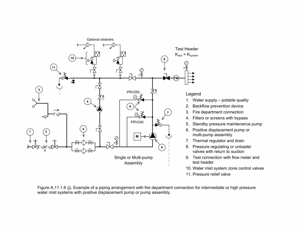
Legend 1. Water supply – potable quality 2. Backflow prevention device 3. Fire department connection 4. Filters or screens with bypass 5. Standby pressure maintenance pump 6. Positive displacement pump or
multi-pump assembly 7. Thermal regulator and drain 8. Pressure regulating or unloader
valves with return to suction 9. Test connection with flow meter and
test header 10. Water mist system zone control valves 11. Pressure relief valve
PRV250
M
PRV240
Test Header Ktest = Ksystem
FM
1
8
7
9
5
6
2
10
4
Figure A.11.1.6 (j). Example of a piping arrangement with fire department connection for intermediate or high pressure water mist systems with positive displacement pump or pump assembly.
Single or Multi-pump Assembly
Optional strainers
3
11
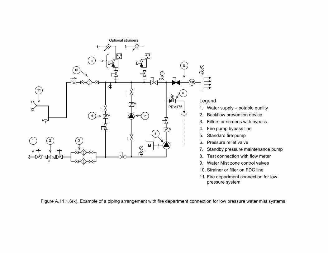
Legend 1. Water supply – potable quality 2. Backflow prevention device 3. Filters or screens with bypass 4. Fire pump bypass line 5. Standard fire pump 6. Pressure relief valve 7. Standby pressure maintenance pump 8. Test connection with flow meter 9. Water Mist zone control valves 10. Strainer or filter on FDC line 11. Fire department connection for low
pressure system
M
PRV175
1
8
7
5
2 3
Figure A.11.1.6(k). Example of a piping arrangement with fire department connection for low pressure water mist systems.
FM
10
6
4
11
Optional strainers
9
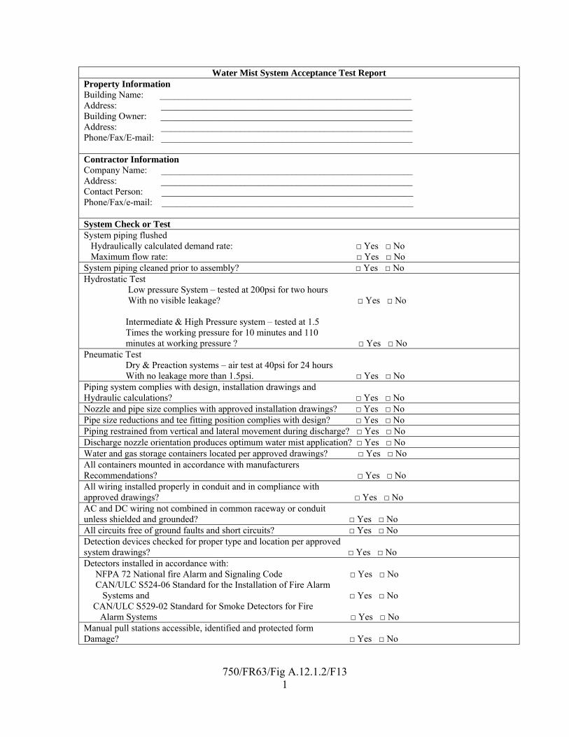
750/FR63/Fig A.12.1.2/F13
1
Water Mist System Acceptance Test Report Property Information Building Name: ______________________________________________________ Address: ______________________________________________________ Building Owner: ______________________________________________________ Address: ______________________________________________________ Phone/Fax/E-mail: ______________________________________________________ Contractor Information Company Name: ______________________________________________________ Address: ______________________________________________________ Contact Person: ______________________________________________________ Phone/Fax/e-mail: ______________________________________________________ System Check or Test System piping flushed Hydraulically calculated demand rate: □ Yes □ No Maximum flow rate: □ Yes □ No System piping cleaned prior to assembly? □ Yes □ No Hydrostatic Test Low pressure System – tested at 200psi for two hours With no visible leakage? □ Yes □ No Intermediate & High Pressure system – tested at 1.5 Times the working pressure for 10 minutes and 110 minutes at working pressure ? □ Yes □ No Pneumatic Test Dry & Preaction systems – air test at 40psi for 24 hours With no leakage more than 1.5psi. □ Yes □ No Piping system complies with design, installation drawings and Hydraulic calculations? □ Yes □ No Nozzle and pipe size complies with approved installation drawings? □ Yes □ No Pipe size reductions and tee fitting position complies with design? □ Yes □ No Piping restrained from vertical and lateral movement during discharge? □ Yes □ No Discharge nozzle orientation produces optimum water mist application? □ Yes □ No Water and gas storage containers located per approved drawings? □ Yes □ No All containers mounted in accordance with manufacturers Recommendations? □ Yes □ No All wiring installed properly in conduit and in compliance with approved drawings? □ Yes □ No AC and DC wiring not combined in common raceway or conduit unless shielded and grounded? □ Yes □ No All circuits free of ground faults and short circuits? □ Yes □ No Detection devices checked for proper type and location per approved system drawings? □ Yes □ No Detectors installed in accordance with: NFPA 72 National fire Alarm and Signaling Code □ Yes □ No CAN/ULC S524-06 Standard for the Installation of Fire Alarm Systems and □ Yes □ No CAN/ULC S529-02 Standard for Smoke Detectors for Fire Alarm Systems □ Yes □ No Manual pull stations accessible, identified and protected form Damage? □ Yes □ No
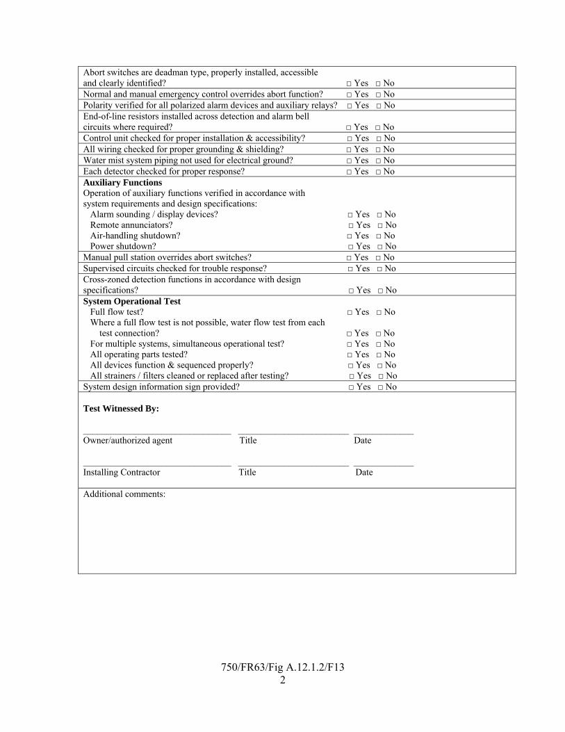
750/FR63/Fig A.12.1.2/F13
2
Abort switches are deadman type, properly installed, accessible and clearly identified? □ Yes □ No Normal and manual emergency control overrides abort function? □ Yes □ No Polarity verified for all polarized alarm devices and auxiliary relays? □ Yes □ No End-of-line resistors installed across detection and alarm bell circuits where required? □ Yes □ No Control unit checked for proper installation & accessibility? □ Yes □ No All wiring checked for proper grounding & shielding? □ Yes □ No Water mist system piping not used for electrical ground? □ Yes □ No Each detector checked for proper response? □ Yes □ No Auxiliary Functions Operation of auxiliary functions verified in accordance with system requirements and design specifications: Alarm sounding / display devices? □ Yes □ No Remote annunciators? □ Yes □ No Air-handling shutdown? □ Yes □ No Power shutdown? □ Yes □ No Manual pull station overrides abort switches? □ Yes □ No Supervised circuits checked for trouble response? □ Yes □ No Cross-zoned detection functions in accordance with design specifications? □ Yes □ No System Operational Test Full flow test? □ Yes □ No Where a full flow test is not possible, water flow test from each test connection? □ Yes □ No For multiple systems, simultaneous operational test? □ Yes □ No All operating parts tested? □ Yes □ No All devices function & sequenced properly? □ Yes □ No All strainers / filters cleaned or replaced after testing? □ Yes □ No System design information sign provided? □ Yes □ No Test Witnessed By: ________________________________ ________________________ _____________ Owner/authorized agent Title Date ________________________________ ________________________ _____________ Installing Contractor Title Date Additional comments:
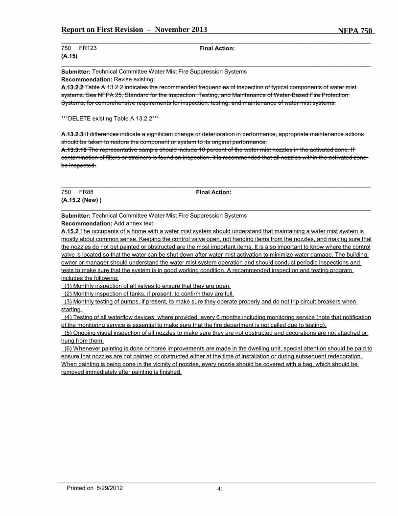
Report on First Revision – November 2013 NFPA 750_______________________________________________________________________________________________750 FR123 Final Action:(A.15)_______________________________________________________________________________________________Submitter: Technical Committee Water Mist Fire Suppression SystemsRecommendation: Revise existing:A.13.2.2 Table A.13.2.2 indicates the recommended frequencies of inspection of typical components of water mistsystems. See NFPA 25, Standard for the Inspection, Testing, and Maintenance of Water-Based Fire ProtectionSystems, for comprehensive requirements for inspection, testing, and maintenance of water mist systems.
***DELETE existing Table A.13.2.2***
A.13.2.3 If differences indicate a significant change or deterioration in performance, appropriate maintenance actionsshould be taken to restore the component or system to its original performance.A.13.3.10 The representative sample should include 10 percent of the water mist nozzles in the activated zone. Ifcontamination of filters or strainers is found on inspection, it is recommended that all nozzles within the activated zonebe inspected.
_______________________________________________________________________________________________750 FR88 Final Action:(A.15.2 (New) )_______________________________________________________________________________________________Submitter: Technical Committee Water Mist Fire Suppression SystemsRecommendation: Add annex text:A.15.2 The occupants of a home with a water mist system should understand that maintaining a water mist system ismostly about common sense. Keeping the control valve open, not hanging items from the nozzles, and making sure thatthe nozzles do not get painted or obstructed are the most important items. It is also important to know where the controlvalve is located so that the water can be shut down after water mist activation to minimize water damage. The buildingowner or manager should understand the water mist system operation and should conduct periodic inspections andtests to make sure that the system is in good working condition. A recommended inspection and testing programincludes the following:
(1) Monthly inspection of all valves to ensure that they are open.(2) Monthly inspection of tanks, if present, to confirm they are full.(3) Monthly testing of pumps, if present, to make sure they operate properly and do not trip circuit breakers when
starting.(4) Testing of all waterflow devices, where provided, every 6 months including monitoring service (note that notification
of the monitoring service is essential to make sure that the fire department is not called due to testing).(5) Ongoing visual inspection of all nozzles to make sure they are not obstructed and decorations are not attached or
hung from them.(6) Whenever painting is done or home improvements are made in the dwelling unit, special attention should be paid to
ensure that nozzles are not painted or obstructed either at the time of installation or during subsequent redecoration.When painting is being done in the vicinity of nozzles, every nozzle should be covered with a bag, which should beremoved immediately after painting is finished.
41Printed on 8/29/2012
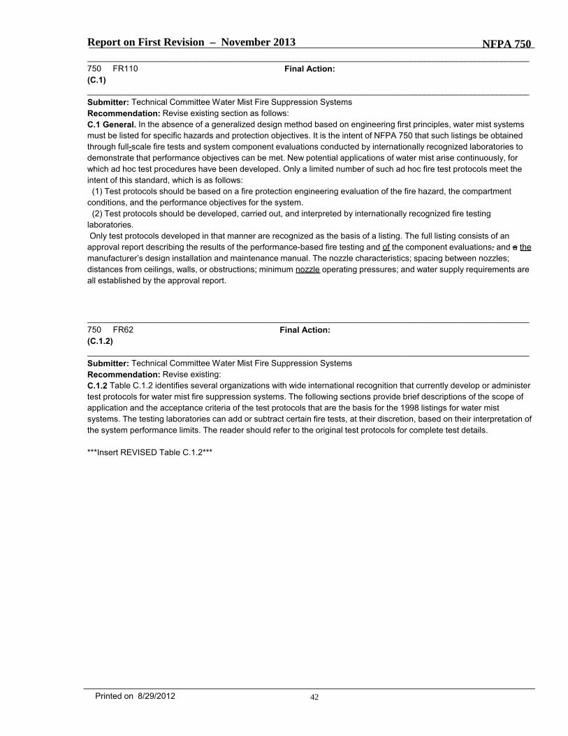
Report on First Revision – November 2013 NFPA 750_______________________________________________________________________________________________750 FR110 Final Action:(C.1)_______________________________________________________________________________________________Submitter: Technical Committee Water Mist Fire Suppression SystemsRecommendation: Revise existing section as follows:C.1 General. In the absence of a generalized design method based on engineering first principles, water mist systemsmust be listed for specific hazards and protection objectives. It is the intent of NFPA 750 that such listings be obtainedthrough full-scale fire tests and system component evaluations conducted by internationally recognized laboratories todemonstrate that performance objectives can be met. New potential applications of water mist arise continuously, forwhich ad hoc test procedures have been developed. Only a limited number of such ad hoc fire test protocols meet theintent of this standard, which is as follows:
(1) Test protocols should be based on a fire protection engineering evaluation of the fire hazard, the compartmentconditions, and the performance objectives for the system.
(2) Test protocols should be developed, carried out, and interpreted by internationally recognized fire testinglaboratories.Only test protocols developed in that manner are recognized as the basis of a listing. The full listing consists of an
approval report describing the results of the performance-based fire testing and of the component evaluations, and a themanufacturer’s design installation and maintenance manual. The nozzle characteristics; spacing between nozzles;distances from ceilings, walls, or obstructions; minimum nozzle operating pressures; and water supply requirements areall established by the approval report.
_______________________________________________________________________________________________750 FR62 Final Action:(C.1.2)_______________________________________________________________________________________________Submitter: Technical Committee Water Mist Fire Suppression SystemsRecommendation: Revise existing:C.1.2 Table C.1.2 identifies several organizations with wide international recognition that currently develop or administertest protocols for water mist fire suppression systems. The following sections provide brief descriptions of the scope ofapplication and the acceptance criteria of the test protocols that are the basis for the 1998 listings for water mistsystems. The testing laboratories can add or subtract certain fire tests, at their discretion, based on their interpretation ofthe system performance limits. The reader should refer to the original test protocols for complete test details.
***Insert REVISED Table C.1.2***
42Printed on 8/29/2012
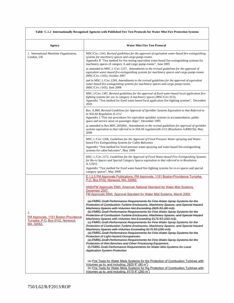
750/L62/R/F2013/ROP
Table C.1.2 Internationally Recognized Agencies with Published Fire Test Protocols for Water Mist Fire Protection Systems
Agency Water Mist Fire Test Protocol
1. International Maritime Organization, London, UK
MSC/Circ.1165, Revised guidelines for the approval of equivalent water-based fire-extinguishing systems for machinery spaces and cargo pump-rooms. Appendix B “Test method for fire testing equivalent water-based fire-extinguishing systems for machinery spaces of category A and cargo pump-rooms”, June 2005
as amended in MSC.1./Circ.1237, Amendments to the revised guidelines for the approval of equivalent water-based fire-extinguishing systems for machinery spaces and cargo pump-rooms (MSC/Circ.1165), October 2007
and in MSC.1./Circ.1269, Amendments to the revised guidelines for the approval of equivalent water-based fire-extinguishing systems for machinery spaces and cargo pump-rooms (MSC/Circ.1165), June 2008
MSC.1/Circ.1387, Revised guidelines for the approval of fixed water-based local application fire-fighting systems for use in category A machinery spaces (MSC/Circ.913), Appendix “Test method for fixed water-based local application fire-fighting systems”, December 2010
Res. A.800, Revised Guidelines for Approval of Sprinkler Systems Equivalent to that Referred to in SOLAS Regulation II-2/12 Appendix 2 “Fire test procedures for equivalent sprinkler systems in accommodation, public space and service areas on passenger ships”, December 1995
as amended in Res.MSC.265(84) , Amendments to the revised guidelines for approval of sprinkler systems equivalent to that referred to in SOLAS regulationIIi-2/12 (Resolution A.800(19)), May 2008
MSC.1./Circ.1268, Guidelines for the Approval of Fixed Pressure Water-spraying and Water-based Fire Extinguishing Systems for Cabin Balconies
Appendix “Test method for fixed pressure water-spraying and water-based fire-extinguishing systems for cabin balconies”, May 2008
MSC.1./Circ.1272, Guidelines for the Approval of Fixed Water-based Fire Extinguishing Systems for Ro-ro Spaces and Special Category Spaces equivalent to that referred to in Resolution A.123(V)
Appendix “Test method for fixed water-based fire-fighting systems for ro-ro spaces and special category spaces”, May 2008
2.
FM Approvals, 1151 Boston-Providence Turnpike, P.O. Box 9102, Norwood, MA, 02062.
E.1.2.5 FM Approvals Publications. FM Approvals, 1151 Boston-Providence Turnpike, P.O. Box 9102, Norwood, MA, 02062. ANSI/FM Approvals 5560, American National Standard for Water Mist Systems, December 2007. FM Approvals 5560, Approval Standard for Water Mist Systems, March 2009. (a) FMRC Draft Performance Requirements for Fine Water Spray Systems for the Protection of Combustion Turbine Enclosures, Machinery Spaces, and Special Hazard Machinery Spaces with Volumes Not Exceeding 2825 ft3 (80 m3). (b) FMRC Draft Performance Requirements for Fine Water Spray Systems for the Protection of Combustion Turbine Enclosures, Machinery Spaces, and Special Hazard Machinery Spaces with Volumes Not Exceeding 9175 ft3 (260 m3). (c) FMRC Draft Performance Requirements for Fine Water Spray Systems for the Protection of Combustion Turbine Enclosures, Machinery Spaces, and Special Hazard Machinery Spaces with Volumes Exceeding 9175 ft3 (260 m3). (d) FMRC Draft Performance Requirements for Fine Water Spray Systems for the Protection of Light Hazard Occupancies. (e) FMRC Draft Performance Requirements for Fine Water Spray Systems for the Protection of Wet Benches and Other Processing Equipment. (f) FMRC Draft Performance Requirements for Water Mist Systems for Local Application System Protection (a) Fire Tests for Water Mists Systems for the Protection of Combustion Turbines with Volumes up to, and including, 2825 ft3 (80 m3) (b) Fire Tests for Water Mists Systems for the Protection of Combustion Turbines with Volumes up to, and including, 9175 ft3 (260 m3)
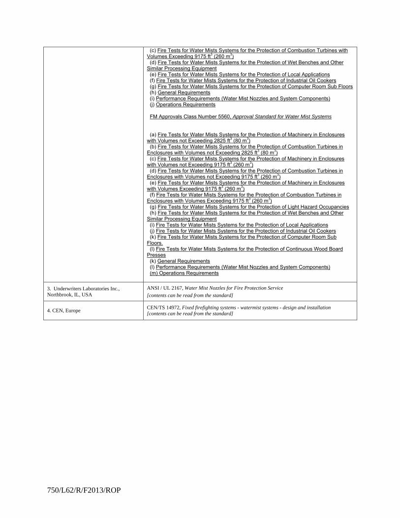
750/L62/R/F2013/ROP
(c) Fire Tests for Water Mists Systems for the Protection of Combustion Turbines with Volumes Exceeding 9175 ft3 (260 m3) (d) Fire Tests for Water Mists Systems for the Protection of Wet Benches and Other Similar Processing Equipment (e) Fire Tests for Water Mists Systems for the Protection of Local Applications (f) Fire Tests for Water Mists Systems for the Protection of Industrial Oil Cookers (g) Fire Tests for Water Mists Systems for the Protection of Computer Room Sub Floors (h) General Requirements (i) Performance Requirements (Water Mist Nozzles and System Components) (j) Operations Requirements FM Approvals Class Number 5560, Approval Standard for Water Mist Systems (a) Fire Tests for Water Mists Systems for the Protection of Machinery in Enclosures with Volumes not Exceeding 2825 ft3 (80 m3) (b) Fire Tests for Water Mists Systems for the Protection of Combustion Turbines in Enclosures with Volumes not Exceeding 2825 ft3 (80 m3) (c) Fire Tests for Water Mists Systems for the Protection of Machinery in Enclosures with Volumes not Exceeding 9175 ft3 (260 m3) (d) Fire Tests for Water Mists Systems for the Protection of Combustion Turbines in Enclosures with Volumes not Exceeding 9175 ft3 (260 m3) (e) Fire Tests for Water Mists Systems for the Protection of Machinery in Enclosures with Volumes Exceeding 9175 ft3 (260 m3) (f) Fire Tests for Water Mists Systems for the Protection of Combustion Turbines in Enclosures with Volumes Exceeding 9175 ft3 (260 m3) (g) Fire Tests for Water Mists Systems for the Protection of Light Hazard Occupancies (h) Fire Tests for Water Mists Systems for the Protection of Wet Benches and Other Similar Processing Equipment (i) Fire Tests for Water Mists Systems for the Protection of Local Applications (j) Fire Tests for Water Mists Systems for the Protection of Industrial Oil Cookers (k) Fire Tests for Water Mists Systems for the Protection of Computer Room Sub Floors. (l) Fire Tests for Water Mists Systems for the Protection of Continuous Wood Board Presses (k) General Requirements (l) Performance Requirements (Water Mist Nozzles and System Components) (m) Operations Requirements
3. Underwriters Laboratories Inc., Northbrook, IL, USA
ANSI / UL 2167, Water Mist Nozzles for Fire Protection Service
[contents can be read from the standard]
4. CEN, Europe CEN/TS 14972, Fixed firefighting systems - watermist systems - design and installation [contents can be read from the standard]
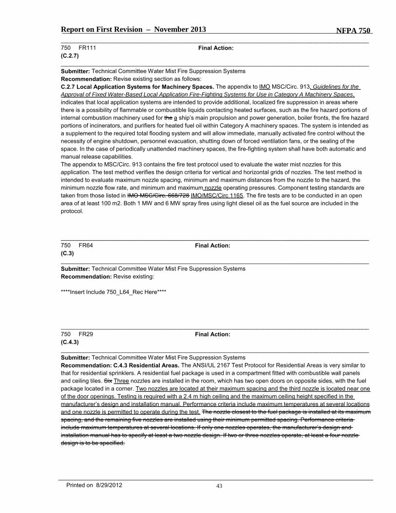
Report on First Revision – November 2013 NFPA 750_______________________________________________________________________________________________750 FR111 Final Action:(C.2.7)_______________________________________________________________________________________________Submitter: Technical Committee Water Mist Fire Suppression SystemsRecommendation: Revise existing section as follows:C.2.7 Local Application Systems for Machinery Spaces. The appendix to IMO MSC/Circ. 913, Guidelines for theApproval of Fixed Water-Based Local Application Fire-Fighting Systems for Use in Category A Machinery Spaces,indicates that local application systems are intended to provide additional, localized fire suppression in areas wherethere is a possibility of flammable or combustible liquids contacting heated surfaces, such as the fire hazard portions ofinternal combustion machinery used for the a ship’s main propulsion and power generation, boiler fronts, the fire hazardportions of incinerators, and purifiers for heated fuel oil within Category A machinery spaces. The system is intended asa supplement to the required total flooding system and will allow immediate, manually activated fire control without thenecessity of engine shutdown, personnel evacuation, shutting down of forced ventilation fans, or the sealing of thespace. In the case of periodically unattended machinery spaces, the fire-fighting system shall have both automatic andmanual release capabilities.The appendix to MSC/Circ. 913 contains the fire test protocol used to evaluate the water mist nozzles for thisapplication. The test method verifies the design criteria for vertical and horizontal grids of nozzles. The test method isintended to evaluate maximum nozzle spacing, minimum and maximum distances from the nozzle to the hazard, theminimum nozzle flow rate, and minimum and maximum nozzle operating pressures. Component testing standards aretaken from those listed in IMO MSC/Circ. 668/728 IMO/MSC/Circ 1165. The fire tests are to be conducted in an openarea of at least 100 m2. Both 1 MW and 6 MW spray fires using light diesel oil as the fuel source are included in theprotocol.
_______________________________________________________________________________________________750 FR64 Final Action:(C.3)_______________________________________________________________________________________________Submitter: Technical Committee Water Mist Fire Suppression SystemsRecommendation: Revise existing:
****Insert Include 750_L64_Rec Here****
_______________________________________________________________________________________________750 FR29 Final Action:(C.4.3)_______________________________________________________________________________________________Submitter: Technical Committee Water Mist Fire Suppression SystemsRecommendation: C.4.3 Residential Areas. The ANSI/UL 2167 Test Protocol for Residential Areas is very similar tothat for residential sprinklers. A residential fuel package is used in a compartment fitted with combustible wall panelsand ceiling tiles. Six Three nozzles are installed in the room, which has two open doors on opposite sides, with the fuelpackage located in a corner. Two nozzles are located at their maximum spacing and the third nozzle is located near oneof the door openings. Testing is required with a 2.4 m high ceiling and the maximum ceiling height specified in themanufacturer’s design and installation manual. Performance criteria include maximum temperatures at several locationsand one nozzle is permitted to operate during the test. The nozzle closest to the fuel package is installed at its maximumspacing, and the remaining five nozzles are installed using their minimum permitted spacing. Performance criteriainclude maximum temperatures at several locations. If only one nozzles operates, the manufacturer’s design andinstallation manual has to specify at least a two nozzle design. If two or three nozzles operate, at least a four nozzledesign is to be specified.
43Printed on 8/29/2012
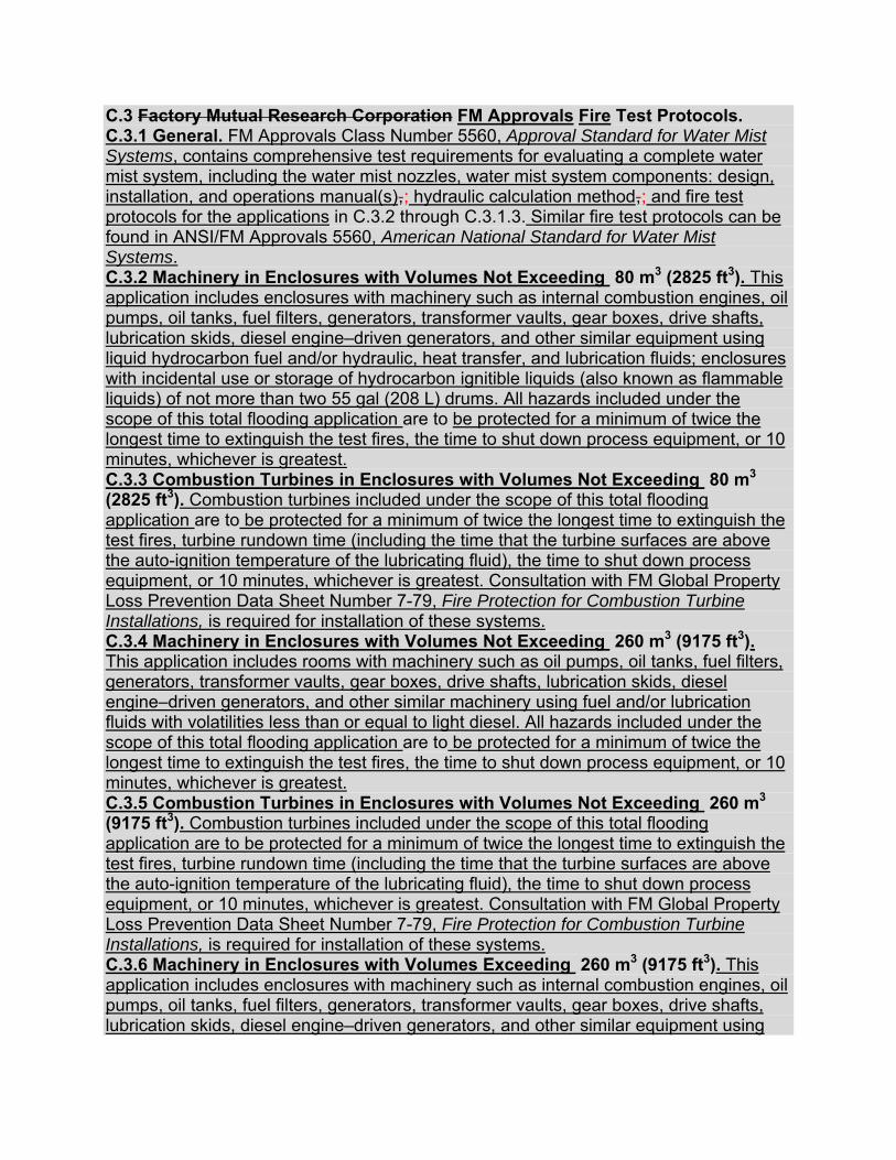
C.3 Factory Mutual Research Corporation FM Approvals Fire Test Protocols. C.3.1 General. FM Approvals Class Number 5560, Approval Standard for Water Mist Systems, contains comprehensive test requirements for evaluating a complete water mist system, including the water mist nozzles, water mist system components: design, installation, and operations manual(s),-; hydraulic calculation method,-; and fire test protocols for the applications in C.3.2 through C.3.1.3. Similar fire test protocols can be found in ANSI/FM Approvals 5560, American National Standard for Water Mist Systems. C.3.2 Machinery in Enclosures with Volumes Not Exceeding 80 m3 (2825 ft3). This application includes enclosures with machinery such as internal combustion engines, oil pumps, oil tanks, fuel filters, generators, transformer vaults, gear boxes, drive shafts, lubrication skids, diesel engine–driven generators, and other similar equipment using liquid hydrocarbon fuel and/or hydraulic, heat transfer, and lubrication fluids; enclosures with incidental use or storage of hydrocarbon ignitible liquids (also known as flammable liquids) of not more than two 55 gal (208 L) drums. All hazards included under the scope of this total flooding application are to be protected for a minimum of twice the longest time to extinguish the test fires, the time to shut down process equipment, or 10 minutes, whichever is greatest. C.3.3 Combustion Turbines in Enclosures with Volumes Not Exceeding 80 m3 (2825 ft3). Combustion turbines included under the scope of this total flooding application are to be protected for a minimum of twice the longest time to extinguish the test fires, turbine rundown time (including the time that the turbine surfaces are above the auto-ignition temperature of the lubricating fluid), the time to shut down process equipment, or 10 minutes, whichever is greatest. Consultation with FM Global Property Loss Prevention Data Sheet Number 7-79, Fire Protection for Combustion Turbine Installations, is required for installation of these systems. C.3.4 Machinery in Enclosures with Volumes Not Exceeding 260 m3 (9175 ft3). This application includes rooms with machinery such as oil pumps, oil tanks, fuel filters, generators, transformer vaults, gear boxes, drive shafts, lubrication skids, diesel engine–driven generators, and other similar machinery using fuel and/or lubrication fluids with volatilities less than or equal to light diesel. All hazards included under the scope of this total flooding application are to be protected for a minimum of twice the longest time to extinguish the test fires, the time to shut down process equipment, or 10 minutes, whichever is greatest. C.3.5 Combustion Turbines in Enclosures with Volumes Not Exceeding 260 m3 (9175 ft3). Combustion turbines included under the scope of this total flooding application are to be protected for a minimum of twice the longest time to extinguish the test fires, turbine rundown time (including the time that the turbine surfaces are above the auto-ignition temperature of the lubricating fluid), the time to shut down process equipment, or 10 minutes, whichever is greatest. Consultation with FM Global Property Loss Prevention Data Sheet Number 7-79, Fire Protection for Combustion Turbine Installations, is required for installation of these systems. C.3.6 Machinery in Enclosures with Volumes Exceeding 260 m3 (9175 ft3). This application includes enclosures with machinery such as internal combustion engines, oil pumps, oil tanks, fuel filters, generators, transformer vaults, gear boxes, drive shafts, lubrication skids, diesel engine–driven generators, and other similar equipment using
liquid hydrocarbon fuel and/or hydraulic, heat transfer, and lubrication fluids; enclosures with incidental use or storage of hydrocarbon ignitible liquids (also known as flammable liquids) of not more than two 208 L (55 gal) drums. All hazards included under the scope of this total flooding application are to be protected for a minimum of twice the longest time to extinguish the test fires, the time to shut down process equipment, or 10 minutes, whichever is greatest. For primary protection consideration, see Section 1.9 of FM 5560, Definitions, “Primary Protection,” and consult the FM Global Property Loss Prevention Data Sheet for the recommended protection of the specific hazard in the applicable occupancy. C.3.7 Combustion Turbines in Enclosures with Volumes Exceeding 260 m3 (9175 ft3). Combustion turbines included under the scope of this total flooding application are to be protected for a minimum of twice the longest time to extinguish the test fires, the turbine rundown time (including the time that the turbine surfaces are above the auto-ignition temperature of the lubricating fluid), the time to shut down process equipment, or 10 minutes, whichever is greatest. Consultation with FM Global Property Loss Prevention Data Sheet Number 7-79, Fire Protection for Combustion Turbine Installations, is required for installation of these systems. For primary protection consideration, see Section 1.9 of FM 5560, Definitions, “Primary Protection.” C.3.8 Light Hazard Occupancies. Typical light hazard occupancies within the scope of this application are defined in FM Global Property Loss Prevention Data Sheet Number 3-26, Fire Protection Water Demand for Nonstorage Sprinklered Properties. The occupancies are defined as Hazard Category 1 (HC-1). Water mist systems are not to be used to protect HC-2, HC-3, or HC-4 occupancies. The applications are limited to ceiling heights of 2.4 m (8 ft) for restricted areas and 5 m (16 ft 5 in.) for unrestricted areas (refer to Section 1.9 of FM 5560, Definitions, “Light Hazard Occupancy,” for specific descriptions of restricted and unrestricted areas). The water supply must be capable of supplying 60 minutes of water to the hydraulically most remote nine automatic nozzles or all automatic nozzles within a 1,500 ft2 (140 m2) demand area, whichever is greater, for systems approved for the protection of unrestricted areas. For installations with less than 1,500 ft2 (140 m2) in area, the water supply are to be capable of supplying 60 minutes of water to all nozzles in the protected area. For systems approved for the protection of restricted areas, the water supply is to be capable of supplying 60 minutes of water to all automatic nozzles within the compartment. Consultation with FM Global Property Loss Prevention Data Sheet Number 4-2, Water Mist Systems, and FM Global Property Loss Prevention Data Sheet Number 3-26, Fire Protection Water Demand for Nonstorage Sprinklered Properties, is required for installation of these systems. C.3.9 Wet Benches and Other Similar Processing Equipment. This application includes tools that consist of ventilated and unventilated compartments, spin rinse dryers, alcohol vapor dryers, chemical and mechanical polishing tools, and step and repeat exposure systems. All hazards included under the scope of this local application are to be protected for a minimum of 10 minutes or twice the longest time to extinguish the worst-case fire scenario, whichever is greater. Consultation with FM Global Property Loss Prevention Data Sheet Numbers 4-2, Water Mist Systems, and 7-7, Semiconductor Fabrication Facilities, is required for installation of these systems.
C.3.10 Local Application Occupancies. Typical local application occupancies within the scope of this section are defined in the FM Global Property Loss Prevention Data Sheet Number 7 Series (Hazards). Consultation with these data sheets is required for installation of these systems. Water mist systems that successfully pass the local application fire scenarios are limited to protection of the following applications:
A. Ignitible liquid (also known as flammable liquid) pool fires where the liquid release can be confined to a diked area. The entire surface of the diked area is to be protected by the water mist system.
B. Ignitible liquid (also known as flammable liquid) channel fires in channels not exceeding the water mist system manufacturer’s maximum specified width and with no limit to channel length.
C. Partially obstructed ignitible liquid (also known as flammable liquid) pool fires where the percentage of obstructed surface is limited to that tested.
D. Spray fires up to 6 MW fueled by ignitible liquids (also known as flammable liquids).
E. Spray and pool fire combinations where the release can be confined to a diked area.
F. Ignitible liquid (also known as flammable liquid) residues (ink and paper dust) on printing presses.
Applicants who want to protect special hazard equipment with ignitible liquids (also known as flammable liquids) with volatilities less than or equal to that of heptane will need to conduct the local application fire scenarios substituting heptane for diesel as the test fuel where appropriate. All hazards are to be protected for a minimum of twice the longest time to extinguish the test fires, time to shut down process equipment, or 10 minutes, whichever is greatest. Consultation with FM Global Property Loss Prevention Data Sheet Number 4-2, Water Mist Systems, is required for installation of these systems. C.3.11 Industrial Oil Cookers. Application of the water mist system is limited to the protection of industrial oil cookers only and does not include the protection of other equipment, such as exhaust ducts, heaters, heat exchangers, and food processing areas, unless tested for these applications. Consideration of the application and use of nozzle protection caps to prevent or reduce the amount of nozzle contamination should be given, and the use of such caps should be included in the fire test and nozzle performance test requirement programs. This local application does not include the protection of other equipment such as exhaust air ducts, heaters, heat exchangers, and food processing or food preparation areas. Consultation with FM Global Property Loss Prevention Data Sheet Numbers 4-2, Water Mist Systems, and 7-20, Oil Cookers, is required for installation of these systems. Industrial oil cookers typically are noninsulated conveyorized fryers or occasional batch kettles, used in food processing plants for chicken, fish, potato products (e.g., fries, chips), doughnuts, and many other food products. These cookers are extremely different in size, configuration, and construction from standard kitchen or restaurant oil cookers or fryers and require a different type of extinguishment system. Industrial oil cookers come in many sizes. They can contain up to approximately,900 L (5000 gallons) of cooking oil. Industrial oil cookers (except for some batch kettles) typically have movable covers or hoods that can be hydraulically operated.
The hood is generally in a closed position during a normal operation periodbut can be opened occasionally for routine maintenance. There are also exhaust stacks connected on top of the hood. The most severe fire incident involving industrial oil cookers is a fire caused by overheating the cooking oil until it reaches its auto-ignition temperature (AIT). Installation of an interlocking system to prevent the oil from reaching its AIT is a normal practice in the industry. However, an AIT fire can still occur due to a system malfunction or simple human error. Thus, all the performance tests proposed in this document require extinguishment of an AIT fire. The AIT fire is particularly challenging because of the rapid spread of flame over the oil surface and the difficulty in extinguishing the fire because flame extinction is required over the entire surface with simultaneous rapid cooling to prevent re-ignition. Exhaust air fans should be interlocked to automatically shut down upon fire detection or operation of the water mist system. Exhaust duct protection, as outlined in FM Global Property Loss Prevention Data Sheet Number 7-78, Industrial Exhaust Systems, is required and should be specified in the manufacturer’s design, installation, operation, and maintenance manual. (Note: Water spray protection for the ducts is required if operation of the duct system during water mist system discharge is necessary. Automatic sprinkler protection is recognized as an effective alternative to water spray.) Commonly used cooking oils, their flash points, and their AITs are listed in Table C.3.11 as a reference only. Canola oil is considered a representative vegetable oil and can be used as the testing medium in industrial oil cooker fire tests. Canola oil has a nominal density equal to 0.93 kg/L (7.8 lb/gal) and nominal specific heat equal to 2.5 kJ/kg · ºC (0.59 Btu/lb · ºF). Alternative cooking oils can be used based on the manufacturer’s intended applications for protection, and approval is limited to cooking oils with flash points and AITs less than or equal to the tested oil.
Table C.3.11. Nominal Flash Points and Auto-Ignition Temperatures (AITs) of Commonly Used Cooking Oils
Cooking Oil Flash Point Auto Ignition Temperature (AIT)
°C °F °C °F Canola 338 641 363 686 Corn 342 647 362 684 Cotton seed 334 633 366 690 Peanut 348 659 370 698 Soybean (soya) 333 631 377 710 Sunflower 340 644 359 678 Palm 328 623 377 710
The agent supply is to be capable of supplying agent to all open nozzles at the maximum rated operating pressure for a minimum of twice the total time needed to extinguish the worst-case fire scenario and subsequently cool the oil to a temperature below its flash point, as established by the testing or 10 minutes, whichever is greater. C.3.12 Computer Room Subfloors. Typical occupancies within the scope of this application are defined in FM Global Property Loss Prevention Data Sheet Numbers 4-2, Water Mist Systems, and 5-32, Electronic Data Processing Systems. System installations are limited to computer room subfloor areas and heights not exceeding those tested. Additionally, the equivalent opening area of the subfloor cannot exceed those tested. The agent supply should be capable of supplying agent to all nozzles at the maximum rated operating pressure for a minimum of twice the longest time to extinguish the test fires or 10 minutes, whichever is greater. This protocol evaluates only the fire extinguishment capabilities of the water mist system. An evaluation of the smoke-cleansing capabilities is not made. Consultation with FM Global Property Loss Prevention Data Sheet Numbers 4-2, Water Mist Systems, and 5-32, Electronic Data Processing Systems, is required for installation of these systems. C.3.13 Continuous Wood Board Presses. This application is further defined in FM Global Property Loss Prevention Data Sheet Number 7-10, Wood Processing and Woodworking Facilities. Application of the water mist system is limited to the protection of the continuous wood board press only and does not include the protection of other equipment unless tested for other applications. All hazards included under the scope of this application are to be protected for a minimum of twice the longest time to extinguish the test fires or 30 minutes, whichever is greater. Consultation with FM Global Property Loss Prevention Data Sheet Numbers 4-2, Water Mist Systems, and 7-10, Wood Processing and Woodworking Facilities, is required for installation of these systems. Factory Mutual Research Corporation (FMRC) has developed the following test protocols, which are the basis for current listings of water mist systems and components [denoted by FMRC as Fine Water Spray (FWS) systems]: (1) FMRC Draft Performance Requirements for Fine Water Spray Systems for the Protection of Combustion Turbine Enclosures, Machinery Spaces, and Special Hazard Machinery Spaces with Volumes Not Exceeding 2825 ft3 (80 m3)
(2) FMRC Draft Performance Requirements for Fine Water Spray Systems for the Protection of Combustion Turbine Enclosures, Machinery Spaces, and Special Hazard Machinery Spaces with Volumes Not Exceeding 9175 ft3 (260 m3) (3) FMRC Draft Performance Requirements for Fine Water Spray Systems for the Protection of Combustion Turbine Enclosures, Machinery Spaces, and Special Hazard Machinery Spaces with Volumes Exceeding 9175 ft3 (260 m3) (4) FMRC Draft Performance Requirements for Fine Water Spray Systems for the Protection of Light Hazard Occupancies (5) FMRC Draft Performance Requirements for Fine Water Spray Systems for the Protection of Wet Benches and Other Processing Equipment (6) FMRC Draft Performance Requirements for Water Mist Systems for Local Application System Protection C.3.1.1 Note that the term machinery space refers to flammable liquid hazards no greater than those of diesel fuel, and the term special hazard machinery space refers to flammable liquid hazards no greater than those of n-heptane. These terms should not be confused with the term machinery space used in the International Maritime Organization (IMO) documents relating to fine water spray. They are not intended to be interchangeable. C.3.1.2 The standards describe fire test performance criteria and methods. Because each fine water spray system is unique in its design and use of components, the component testing of each fine water spray system is evaluated on a case-by-case basis. The components are tested for functionality, performance, integrity, and reliability. The manufacturers’ design, installation, and maintenance manual(s) are reviewed for technical content and clarity. The supplied hydraulic calculations are also reviewed. C.3.2 FMRC Draft Performance Requirements for Fine Water Spray Systems for the Protection of Combustion Turbine Enclosures, Machinery Spaces, and Special Hazard Machinery Spaces with Volumes Not Exceeding 2825 ft3 (80 m3). C.3.2.1 The objective of this standard is to ensure that the fine water spray system extinguishes spray and pool fires that can occur, for example, due to breaks in lubrication, hydraulic, or fuel lines. Typically, these fires are highly shielded. While spray fires can occur only as the result of a supply line break, pool fires can occur as a result of a breakage or as a result of a small leak over a large period of time. This standard is limited to volumes not exceeding 80 m3 (2825 ft3). The FMRC standard assumes automatic interlocks for the following: (1) All fuel supply lines (for combustion turbines, bearing lubrication can be left on to allow the turbine to coast down) (2) Door closures (3) Ventilation shutdown (4) Electrical systems C.3.2.2 The water supply required is dependent on the application. For combustion turbines, the water supply has to be sufficient to protect the turbine for the duration of its coast downtime. For machinery spaces and special hazard machinery spaces, the protection time is 10 minutes. C.3.2.3 The detection is by means of heat detectors. The detection is so designed as to detect the fire and activate the fine water spray system within 60 seconds of the ignition.
C.3.2.4 The fine water spray system has to extinguish all spray and pool fires within 5 minutes from the time of ignition. Tests are conducted in closed enclosures as well as enclosures with natural ventilation. For optional protection of insulated combustion turbines, the insulation mat can be suppressed rather than extinguished. C.3.2.5 In addition to the fire performance criteria, fine water spray systems used for the protection of combustion turbines cannot cause damage to the turbine by means of thermal shock or cracking of the turbine casing or induce blade rubbing. The rate of cooling of the steel test plate (1m×2m×5cmthick) must not exceed limits set by FMRC. It can be more difficult to successfully pass the cooling test than to pass the fire tests, and the results of the cooling test often indicate the number, type, and placement of the fine water spray nozzles. C.3.3 FMRC Draft Performance Requirements for Fine Water Spray Systems for the Protection of Combustion Turbine Enclosures, Machinery Spaces, and Special Hazard Machinery Spaces with Volumes Not Exceeding 9175 ft3 (260 m3). C.3.3.1 The objective of this standard is to ensure that the fine water spray system extinguishes spray and pool fires that can occur, for example, due to breaks in lubrication, hydraulic, or fuel lines. Typically, these fires are highly shielded. While spray fires can occur only as the result of a supply line break, pool fires can occur as a result of a breakage or as a result of a small leak over a large period of time. This standard is limited to volumes not exceeding 260 m3 (9175 ft3). The FMRC standard assumes automatic interlocks for the following: (1) All fuel supply lines (for combustion turbine, bearing lubrication can be left on to allow the turbine to coast down) (2) Door closures (3) Ventilation shutdown (4) Electrical systems C.3.3.2 The water supply required is dependent on the application. For combustion turbines, the water supply has to be sufficient to protect the turbine for the duration of its coast downtime. For machinery spaces and special hazard machinery spaces, the protection time is 10 minutes. C.3.3.3 The detection is by means of heat detectors. The detection is so designed as to detect the fire and activate the fine water spray system within 60 seconds of the ignition. C.3.3.4 The fine water spray system has to extinguish all spray and pool fires within 5 minutes from the time of ignition. Tests are conducted in closed enclosures as well as enclosures with natural ventilation. For optional protection of insulated combustion turbines, the insulation can be suppressed rather than extinguished. In addition to demonstrating performance in volumes not exceeding 260 m3 (9175 ft3), systems also have to demonstrate the capability to perform in small [130 m3 (4590 ft3)] enclosures. C.3.3.5 In addition to the fire performance criteria, fine water spray systems used for the protection of combustion turbines cannot cause damage to the turbine by means of thermal shock, cause cracking of the turbine casing, or induce blade rubbing. The rate of cooling of the steel test plate (1m×2m×5cm thick) cannot exceed limits set by FMRC. It can be more difficult to successfully pass the cooling test than to pass the fire tests,
and the results of the cooling test often indicate the number, type, and placement of the fine water spray nozzles. C.3.4 FMRC Draft Performance Requirements for Fine Water Spray Systems for the Protection of Combustion Turbine Enclosures, Machinery Spaces, and Special Hazard Machinery Spaces with Volumes Exceeding 9175 ft3 (260 m3). C.3.4.1 The objective of this standard is to ensure that the fine water spray system extinguishes spray and pool fires that can occur, for example, due to breaks in lubrication, hydraulic, or fuel lines. Typically, these fires are highly shielded. Although spray fires can occur only as the result of a supply line break, pool fires can occur as a result of a breakage or as a result of a small leak over a large period of time. The FMRC standard assumes automatic interlocks for the following: (1) All fuel supply lines (for combustion turbines, bearing lubrication can be left on to allow the turbine to coast down) (2) Door closures (3) Ventilation shutdown (4) Electrical systems C.3.4.2 This standard is based on the IMO Standard for Shipboard Machinery Spaces, although the hazards discussed in both documents are different. Due to differences in system design and performance, extrapolation of results to larger room sizes is not permitted by FMRC at this time. C.3.4.3 The water supply required is dependent on the application. For combustion turbines, the water supply has to be sufficient to protect the turbine for the duration of its coast downtime. For machinery spaces and special hazard machinery spaces, the protection time is 60 minutes. Typically, the volumes tested exceed 800 m3 (28,230 ft3). C.3.4.4 The detection is by means of heat detectors. The detection is so designed as to detect the fire and activate the fine water spray system within 60 seconds of the ignition. C.3.4.5 The fine water spray system has to extinguish all spray, pool, and crib fires within 30 minutes from the time of ignition. The exception is a small shielded diesel pool fire that has to be suppressed. Tests are conducted in enclosures with natural ventilation. For optional protection of insulated combustion turbines, the insulation mat can be suppressed rather than extinguished. C.3.4.6 In addition to the fire performance criteria, fine water spray systems used for the protection of combustion turbines cannot cause damage to the turbine by means of thermal shock or cracking of the turbine casing or induce blade rubbing. The rate of cooling of the steel test plate (1 m × 2 m × 5 cm thick) cannot exceed limits set by FMRC. It can be more difficult to successfully pass the cooling test than to pass the fire tests, and the results of the cooling test often indicate the number, type, and placement of the fine water spray nozzles. C.3.5 FMRC Draft Performance Requirements for Fine Water Spray Systems for the Protection of Light Hazard Occupancies. C.3.5.1 The objective of this standard is to ensure that the fine water spray system controls fires typically found in light hazard occupancies and prevents the spread of the fire beyond the room or area of origin. These fires typically involve furnishings and wall coverings. This standard limits the heights of enclosed spaces to 2.4 m (8 ft) and the heights of unrestricted spaces to 5 m (16 ft 5 in.).
C.3.5.2 This standard is based on the IMO Standard for Shipboard Corridors, Cabins, and Public Spaces, although the hazards discussed in both documents are different. C.3.5.3 The water supply required is 60 minutes for the most remote nine nozzles at the rated operating pressure. C.3.5.4 The detection is by means of individual heat responsive elements on the nozzles. The nozzles should meet FMRC requirements for quick response sprinklers and are limited to a maximum nominal temperature rating of 107°C (225°F). Nozzle spacing is to be uniform with uniform spacing, preferably one-half of the standard nozzle spacing, from the wall. C.3.5.5 The fire performance tests consist of three test areas: small compartment, large compartment, and open space. C.3.5.5.1 The small compartment [3 m × 4 m × 2.4 m (10 ft × 13 ft × 8 ft) high] has a door 0.8 m × 2.2 m (2 ft 6 in. × 7 ft 2 in.) high and represents a small ship cabin. The fuel package for this room consists of two bunk beds identical to the IMO specification. The purpose of this test is to delineate mist nozzles from sprinklers. The fire is ignited on the lower mattress, and the test methodology is identical to that specified in the IMO test series. Pass/fail criteria are based on damage of the lower bunk (maximum of 40 percent), ceiling surface temperature over ignition [maximum of 260°C (500°F)], and a maximum gas temperature 76 mm (3 in.) below the ceiling of 315°C (600°F). C.3.5.5.2 The large compartment [having equal sides not exceeding 6 m (20 ft) and a height of 2.4 m (8 ft)] has two doors [each 0.8 m × 2.2 m (2 ft 6 in. × 7 ft 2 in.) high] located in diagonally opposite corners. A nozzle is placed in the doorway opposite the fuel package. The fuel package and test method are identical to the IMO specification. The heptane under the wood crib is ignited first, then followed 40 seconds later by the ignition of the excelsior. The doorway nozzles do not operate (indicating that the fire would not have spread to an adjacent area). Additional pass/fail criteria include ceiling surface temperature over ignition [maximum of 265°C (510°F)] and a maximum gas temperature 76 mm (3 in.) below the ceiling of 315°C (600°F). C.3.5.5.3 The open space test is conducted under a ceiling with a minimum area of 80m2 (860 ft2) to simulate an uninterrupted area and a ceiling height of 5 m (16 ft 5 in.). At least 16 nozzles are installed in the ceiling and the fuel package (sofas, as outlined in the IMO specification) are to be arranged per the IMO specification. The test is conducted three times: once each with the ignition under one nozzle, between two nozzles, and between four nozzles. Pass/fail criteria are based on fewer than five nozzles operating, at least one unoperated nozzle beyond those that operate, damage of the sofa cushions (maximum of 50 percent), ceiling surface temperature over ignition [maximum of 260°C (500°F)], and a maximum gas temperature 76mm(3 in.) below the ceiling of 315°C (600°F). C.3.6 FMRC Draft Performance Requirements for Fine Water Spray Systems for the Protection of Wet Benches and Other Processing Equipment. C.3.6.1 The objective is to ensure that the fine water spray system extinguishes pool fires typically found in wet benches and other similar clean room processing equipment. C.3.6.2 The detection system has to be approved specifically for use in wet bench applications. Fine water spray systems used for this application are typically of the zoned, deluge type. Operating elements currently used in automatic sprinklers have not been shown to be sufficiently fast enough to prevent significant nonthermal damage.
C.3.6.3 The simulated clean room is 5.5m× 3.7m× 3.7m(18 ft × 12 ft × 12 ft) high with porous ceiling and floor plates. An airflow (downward) with a velocity of 0.31 m/sec (60 ft/min) is maintained throughout the test. The minimum airflow by the open face of the wet bench is 4.5 m3/min/linear m (150 ft3/ min/linear ft). The wet bench measures approximately 2.3 m × 1.4m×2m(7.5 ft × 4.5 ft × 6.5 ft) high and is divided into two areas: the ventilated subsurface (or plenum) area and the working surface area. The subsurface dimensions are 0.8 m × 2.3 m × 0.6 m (2.6 ft × 7.5 ft × 2 ft) high. The working surface area is 0.8 m × 2.3 m (2.6 ft × 7.5 ft). C.3.6.4 All fires have to be extinguished in less than 60 seconds. C.3.6.5 Various fire scenarios are conducted to test the fine water spray system for the ventilated subsurface area. These include five pool fires (various sizes) utilizing polypropylene beads and solid coupons for fuel and at least one pool fire for each of the following flammable liquids: acetone, isopropyl alcohol (IPA), and n-heptane. The pan sizes and fire locations for the flammable liquid pool fire are at the discretion of FMRC based on observations of the fine water spray system. Obstructions are placed within the subsurface area such that approximately 50 percent of the nozzle discharge is blocked. C.3.6.6 Two tests are conducted to determine the effectiveness of a single nozzle in an unventilated space utilizing the subsurface area as a test chamber. The first test utilizes a polypropylene pool fire, and the second test uses a flammable liquid pool fire. Pan size and flammable liquid are at the discretion of FMRC based on the outcome of the ventilated subsurface tests. Suitable barriers are placed in the test area to prevent direct impingement on the fire and to provide 50 percent blockage of the discharge. C.3.6.7 Several fire scenarios are conducted to test the fine water spray system for the working surface area. These include five pool fires (various sizes) utilizing polypropylene beads and solid coupons for fuel and at least one pool fire for each of the following flammable liquids: acetone, isopropyl alcohol (IPA), and n-heptane. The pan sizes and fire locations for the flammable liquid pool fire are at the discretion of FMRC based on observations made of the fine water spray system. The flammable liquid fires are also tested at the minimum and maximum nozzle heights, as specified by the manufacturer. A splashing test is conducted in which a single nozzle, located at the minimum vertical height above a pan of liquid containing dye, is discharged at the maximum pressure. None of the contents of the liquid pool are splashed outside a 0.4 m (16 in.) diameter circle centered on the pool. C.3.7 FMRC Draft Fire Test Protocol for Water Mist Systems for Local Application Protection. C.3.7.1 The objective of this standard is to ensure that the water mist system will extinguish combustible liquid spray and pool fires. These fires can occur on printing press stands, dip tanks, quench tanks, or lube oil–conditioning systems. The standard assumes the following: (1) Room ventilation is normal. (2) Obstructions over the protected area do not exceed that tested.
(3) Fluid is contained within the diked area. C.3.7.2 The time required to extinguish the fire scenarios will be reported. The water supply required depends on the occupancy and the authority having jurisdiction. C.3.7.3 The system is to be automatically activated by a listed heat or flame detection system. C.3.7.4 The water mist system must extinguish the following fires at the maximum and minimum nozzle elevations and spacing. Maximum and minimum heights apply as follows: (1) For square pool fires, maximum height only for 1 m × 1 m and2m×2mpools; maximum and minimum heights for the 3 m × 3 m pool (2) For channel fires, maximum height only for Y and 2Y lengths; maximum and minimum heights for 3Y length (3) For heptane spray fires, maximum and minimum heights (4) For combined pool and spray fires, maximum height only (5) For offset pool fire, obstructed pool fire, and spray fire with
external ignition source, maximum and minimum heights C.3.7.4.1 Pool Fires. Pool fires are to be in square shapes from 1m2, 4 m2, and9m2 (10.8 ft2, 43.6 ft2, and 96 ft2) in area. C.3.7.4.2 Obstructed Pool Fires. The obstruction must be at least equivalent to a 0.6 m (2 ft) diameter drum located 0.5 m (1.6 ft) over the center of the pool. C.3.7.4.3 Channel Fires. Channel fires are to be at the width of the channel and at lengths of one, two, and three times the width. C.3.7.4.4 Spray Fires. Six MW heptane spray fires are conducted with the spray fire axis in the horizontal and vertical directions. C.3.7.4.5 Spray and Pool Fires. Horizontal spray fire tests are conducted with a 6 MW diesel spray fire at two different elevations and two different locations above the surface ofa2m×2m diesel pool fire. A 45 degree spray fire is conducted with a 6 MW diesel spray fire at two locations at one elevation above a 2 m × 2 m diesel pool fire. C.3.7.4.6 Diesel Soaked Paper Dust Fire. A fire involving a quantity of diesel fuel soaked into paper dust. C.3.7.5 The tests are conducted in enclosures large enough so that oxygen concentrations do not decrease below 20 percent.
Report on First Revision – November 2013 NFPA 750_______________________________________________________________________________________________750 FR39 Final Action:(C.4.5)_______________________________________________________________________________________________Submitter: Technical Committee Water Mist Fire Suppression SystemsRecommendation: C.4.5 Ordinary Hazard Group 1. The ANSI/UL 2167 Test Protocol for Ordinary Hazard Group 1Hazard Areas requires that fire tests be conducted both under an open ceiling and in a corner arrangement. The firstseries of fire tests is conducted under a smooth flat ceiling having provisions for venting gases around the perimeter setat the maximum height specified in the manufacturer’s design and installation manual. The fire source consists of a 4.7m wide × 5.9 m long × 2.1 2.4 m high array of Class II commodity (double tri-wall corrugated paper cartons with afive-sided steel liner on a 107 cm × 107 cm × 12.7 cm high hardwood pallet). During the 45-minute test, ceiling steeltemperatures cannot exceed 282 540°C (540 1000°F) for more than 5 minutes, the number of operating nozzles cannot
exceed a design area of 93 m2, and damage to the commodity cannot exceed 50 percent. The corner fire tests aresimilar to the IMO public space corner tests except that empty cardboard cartons are used in lieu of the sofas.
_______________________________________________________________________________________________750 FR66 Final Action:(E.1.1)_______________________________________________________________________________________________Submitter: Technical Committee Water Mist Fire Suppression SystemsRecommendation: Revise text to read as follows:E.1.1 NFPA Publications. National Fire Protection Association, 1 Batterymarch Park, Quincy, MA 02169-7471NFPA 3, Recommended Practice for Commissioning and Integrated Testing of Fire Protection and Life Safety Systems,2012 edition.NFPA 13, Standard for the Installation of Sprinkler Systems, 2010 edition.NFPA 15, Standard for Water Spray Fixed Systems for Fire Protection, 2007 edition.NFPA 20, Standard for the Installation of Stationary Pumps for Fire Protection, 2010 edition.NFPA 25, Standard for the Inspection, Testing, and Maintenance of Water-Based Fire Protection Systems, 2008 edition.NFPA 70®, National Electrical Code®, 2008 edition.NFPA 72®, National Fire Alarm and Signaling Code, 2010 edition.NFPA 502, Standard for Road Tunnels, Bridges, and Other Limited Access Highways, 2011 edition.Cote, A. E., and J. L. Linville, eds. “Water Mist Suppression Systems,” in Fire Protection Handbook, 18th edition.
_______________________________________________________________________________________________750 FR76 Final Action:(E.1.2.5 (New) )_______________________________________________________________________________________________Submitter: Technical Committee Water Mist Fire Suppression SystemsRecommendation: Add new text to read as follows:E.1.2.5 FM Approvals Publications. FM Approvals, 1151 Boston-Providence Turnpike, P.O. Box 9102, Norwood, MA,02062.ANSI/FM Approvals 5560, American National Standard for Water Mist Systems, December 2007.FM Approvals 5560, Approval Standard for Water Mist Systems, March 2009.
44Printed on 8/29/2012
Report on First Revision – November 2013 NFPA 750_______________________________________________________________________________________________750 FR65 Final Action:(E.1.2.10)_______________________________________________________________________________________________Submitter: Technical Committee Water Mist Fire Suppression SystemsRecommendation: Revise text to read as follows:
E.1.2.910 UL Publications. Underwriters Laboratories Inc., 333 Pfingsten Road, North brook, IL 60062-2096.ANSI/UL 2167, Standard for Water Mist Nozzles for Fire Protection Service, 2011 2002 with revisions through January
2009
45Printed on 8/29/2012

![First Revision Print - NFPA · 2012-07-26 · 731/FR 2/F2013/FD First Revision No. 2:NFPA 731-2011 [FR 2: FileMaker] Chapter 4 Fundamentals 4.1 Application. 4.1.1 The provisions of](https://img.pdfslide.us/doc/110x75/5e936275082ddd5c1d420098/first-revision-print-nfpa-2012-07-26-731fr-2f2013fd-first-revision-no-2nfpa.jpg)