Embed Size (px)
DESCRIPTION
Aerodynamic analysis of vehicle bodies
Citation preview
LLNL-TR-628153
Aerodynamic drag reduction of class 8heavy vehicles: a full-scale wind tunnelstudy
J. Ortega, K. Salari, A. Brown, R. Schoon
March 19, 2013
Disclaimer
This document was prepared as an account of work sponsored by an agency of the United States government. Neither the United States government nor Lawrence Livermore National Security, LLC, nor any of their employees makes any warranty, expressed or implied, or assumes any legal liability or responsibility for the accuracy, completeness, or usefulness of any information, apparatus, product, or process disclosed, or represents that its use would not infringe privately owned rights. Reference herein to any specific commercial product, process, or service by trade name, trademark, manufacturer, or otherwise does not necessarily constitute or imply its endorsement, recommendation, or favoring by the United States government or Lawrence Livermore National Security, LLC. The views and opinions of authors expressed herein do not necessarily state or reflect those of the United States government or Lawrence Livermore National Security, LLC, and shall not be used for advertising or product endorsement purposes.
This work performed under the auspices of the U.S. Department of Energy by Lawrence Livermore National Laboratory under Contract DE-AC52-07NA27344.
Aerodynamic drag reduction of class 8 heavy
vehicles: a full-scale wind tunnel study
J. Ortega∗, K. Salari†, A. Brown‡, R. Schoon§
11/28/2012
Corresponding author: Kambiz Salari, Lawrence Livermore National Laboratory, P.O. Box
808, L-090, Livermore, CA 94551; e-mail: [email protected]; phone: 925-424-4635
∗Staff Scientist, Engineering, Lawrence Livermore National Laboratory, Livermore, CA†Staff Scientist, Computation, Lawrence Livermore National Laboratory, Livermore, CA‡Former Aerodynamics Experimental Engineer, Navistar, Inc., Fort Wayne, IN§Former Chief Engineer, Aerodynamics, Navistar, Inc., Fort Wayne, IN
1
Aerodynamic drag reduction of class 8 heavy vehicles, Ortega, et al., 11/28/2012 2
Abstract
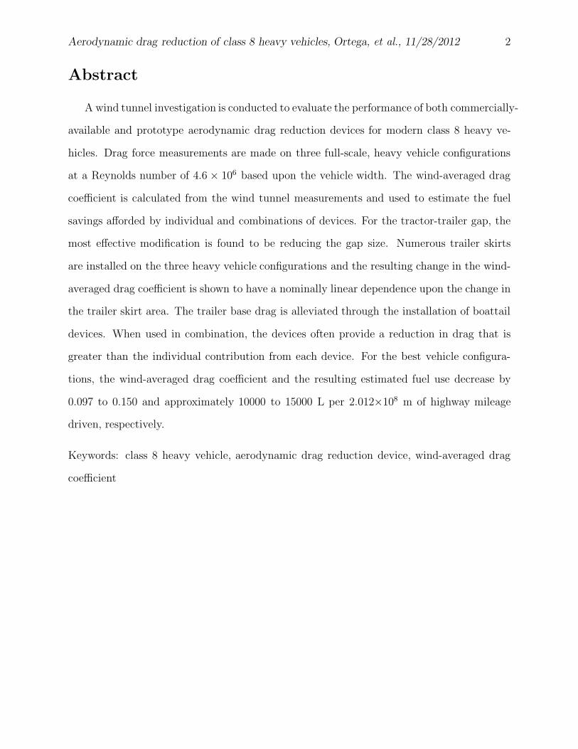
A wind tunnel investigation is conducted to evaluate the performance of both commercially-
available and prototype aerodynamic drag reduction devices for modern class 8 heavy ve-
hicles. Drag force measurements are made on three full-scale, heavy vehicle configurations
at a Reynolds number of 4.6 × 10⁶ based upon the vehicle width. The wind-averaged drag
coefficient is calculated from the wind tunnel measurements and used to estimate the fuel
savings afforded by individual and combinations of devices. For the tractor-trailer gap, the
most effective modification is found to be reducing the gap size. Numerous trailer skirts
are installed on the three heavy vehicle configurations and the resulting change in the wind-
averaged drag coefficient is shown to have a nominally linear dependence upon the change in
the trailer skirt area. The trailer base drag is alleviated through the installation of boattail
devices. When used in combination, the devices often provide a reduction in drag that is
greater than the individual contribution from each device. For the best vehicle configura-
tions, the wind-averaged drag coefficient and the resulting estimated fuel use decrease by
0.097 to 0.150 and approximately 10000 to 15000 L per 2.012×10⁸ m of highway mileage
driven, respectively.
Keywords: class 8 heavy vehicle, aerodynamic drag reduction device, wind-averaged drag
coefficient
Aerodynamic drag reduction of class 8 heavy vehicles, Ortega, et al., 11/28/2012 3
1 Introduction
Combination heavy vehicles in the United States consume approximately 30 billion
gallons of fuel each year [17]. By 2035, this number is expected to increase to approximately
40 billion gallons per year as a result of the continued growth of the highway transportation
sector [1]. The majority of the shaft power derived from this fuel is used to overcome
aerodynamic drag at highway speeds, while the remaining portion is dissipated through tire
rolling resistance and drive train friction [5, 46].
These aerodynamic losses were first given considerable attention following the 1970’s oil
crisis. Prior to that time, heavy vehicles were primarily designed for functionality and ease
of manufacturing and, therefore, little thought was given to aerodynamics, which resulted
in box-shaped tractors and trailers. To improve the fuel economy of these vehicles, several
conference workshops and numerous research programs and studies were conducted on heavy
vehicle aerodynamics [5, 6, 8, 9, 10, 11, 12, 16, 21, 28, 29, 33, 36, 37, 38, 39, 47, 48, 50,
53, 56, 57, 58, 64]. Although the entire vehicle was investigated for various avenues of
reducing drag, the primary focus of these efforts was the aerodynamics of the tractor and
the front of the trailer. From wind tunnel, track, and road test data, it was shown that
considerable reductions in aerodynamic drag could be achieved through tractor roof fairings,
skirts, aerodynamic visors, rounding of the tractor and trailer front edges, and through the
installation of trailer nose cones. Since these modifications did not significantly hamper the
operational performance of the heavy vehicles, the trucking industry generally accepted them,
which led to a definitive transition to the modern aerodynamic tractor and the rounded,
front-corner trailer. These aerodynamic changes, along with improvements in tire, engine,
and component designs, resulted in an increase in the fuel economy of heavy vehicles from
99000 L/2.012×108 m driven (4.8 mpg) in 1970 to 88000 L/2.012×108 m driven (5.4 mpg)
in 2008, where 2.012×10⁸ m (125000 mi) is a nominal distance traveled by a heavy vehicle
each year [17]. For more thorough reviews of the early aerodynamic developments of heavy
Aerodynamic drag reduction of class 8 heavy vehicles, Ortega, et al., 11/28/2012 4
vehicles, the reader is directed to [13, 14, 38, 48, 49].
With the present day rise of fuel costs and the uncertainty of foreign oil supplies, there
is a continued demand in the United States for increased fuel economy of heavy vehicles.
Therefore, a number of the drag reduction devices and concepts that were not originally
implemented in the design of modern day heavy vehicles have become potential candidates
for further fuel economy improvements. Some of these second generation devices include
boattails and trailer skirts, as well as tractor-trailer gap devices [2, 3, 7, 9, 12, 13, 14, 15, 22,
23, 31, 32, 35, 38, 42, 44, 45, 54, 55, 59, 60, 61, 62]. A number of studies, a sampling of which
are shown in Tables 1-4, have either measured or estimated that these devices can produce
fuel economy improvements when they are used both individually and in combination with
one another. (It should be noted that the fuel savings data summarized in each of these
tables are for various tractor-trailer geometries, Reynolds numbers, and drag reduction device
designs.) From these studies, the average fuel savings of the gap, skirt, and boattail devices
are about 3000, 5000, and 4000 L/2.012×108 m driven of highway mileage, respectively,
while that of their combinations is on average approximately 12000 L/2.012×108 m driven
of highway mileage. Other research concepts that have been recently investigated include
tractor and trailer base blowing systems [18, 19, 43], fluidic actuators [26, 41, 51, 52, 63] and
trailer wheel and bogie fairings [15, 42, 55].
Despite the fuel economy benefits of these second generation devices, they have not been
widely accepted by the trucking industry due to both operational issues and the nature of
heavy vehicle manufacturing in the United States. Unlike the first generation devices, a
number of the second generation devices are more susceptible to damage, restrict access to
portions of the vehicle, or must be continually deployed and stowed during routine operations.
For example, the trailer skirts reduce the ground clearance of the vehicle, causing them to
scrape against the ground at railroad crossings and sunken loading docks. In addition,
the skirts can limit access to the trailer underbody for tire and brake inspections. The
Aerodynamic drag reduction of class 8 heavy vehicles, Ortega, et al., 11/28/2012 5
gap devices, especially those constructed from aluminum sheet metal, are prone to damage
during maneuvers that require the vehicle to articulate to extreme angles. Boattails are
the least accepted of these devices since the trailer base upon which they are installed
receives the most interaction during fleet operations. As a result, the boattail must be
stowed before backing the trailer into the loading dock, thus requiring the driver or dock
worker to manually perform this additional task. Some manufacturers attempt to circumvent
this step by designing the boattail to self-retract when the vehicle comes to a stop. However,
freezing and snowy conditions can potentially hamper this self-actuation motion. As a result
of these many shortcomings, the majority of fleet operators have purposely decided not to
adopt these devices in their current forms [30].
Clearly, there is a need to improve the design of second generation devices so that the
trucking industry will welcome them and thereby benefit from the fuel economy gains that
can be had through their implementation. This can only be accomplished through a coordi-
nated effort of the trucking industry, aerodynamic researchers, and government regulations
[13]. Therefore, we have formed a multi-disciplinary team comprised of trucking industry
manufacturers (tractor, trailer, tire, and drag reduction devices), a commercial fleet, and
a national laboratory. The ultimate goal of this team is to develop a trailer with factory-
installed devices that are not only effective in reducing aerodynamic drag, but are also robust
and operationally-minded.
The purpose of the present study is to take the first step towards accomplishing this
goal by evaluating the performance of a number of drag reduction devices, the majority of
which are currently on the market. A full-scale wind tunnel investigation is employed to
measure the changes in the drag coefficient that arise from the installation of these devices
and to obtain a better understanding of how different devices affect the performance of other
devices installed simultaneously. The utility of this experimental approach is that it provides
a controlled environment for investigating the devices under varying wind speeds and vehicle
Aerodynamic drag reduction of class 8 heavy vehicles, Ortega, et al., 11/28/2012 6
yaw angles, as well as eliminating any Reynolds number effects. In addition, the full-scale
model obviously has all of the details of a modern heavy vehicle along with those specific to
the various drag reduction devices. Similar full-scale wind tunnel studies of heavy vehicles
and devices have been conducted in the past, though these were restricted to either a limited
number of devices or to a shortened trailer with a high tunnel blockage due to size restrictions
of the wind tunnel test section [15, 31, 32]. Before discussing the wind tunnel setup, we first
describe in the following section the theory of the wind-averaged drag coefficient, which is
employed as a metric for comparing the performance of the various devices.
2 Wind-Averaged Drag Coefficient
When a vehicle is in motion, the body-axis drag coefficient is given by the expression,
CA = DA/(1
2ρV 2
r A), where DA is the drag force in the direction along the axis of the vehicle,
Vr is the wind speed relative the vehicle, ρ is the air density, and A is the vehicle cross-
sectional area. While the information obtained from CA at multiple yaw angles, ψ, is useful,
it is somewhat cumbersome since this quantity does not summarize the performance of a drag
reduction device into a single quantity that can be easily compared to that of other devices.
In addition, the mean value of CA over a range of yaw angles is insufficient since it does not
account for the fact that crosswind velocities cause a vehicle traveling at a particular speed
to experience certain yaw angles more than others. A quantity that resolves both of these
issues is the wind-averaged drag coefficient, CAwavg, which is derived as follows [5, 8, 27].
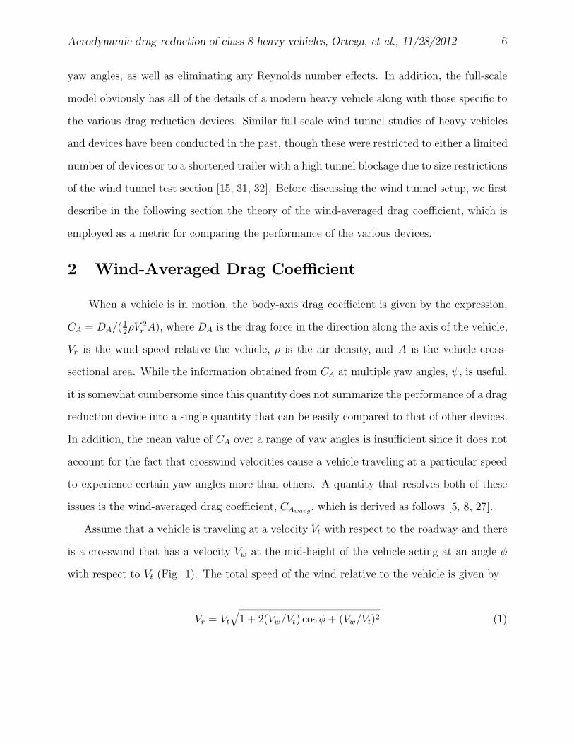
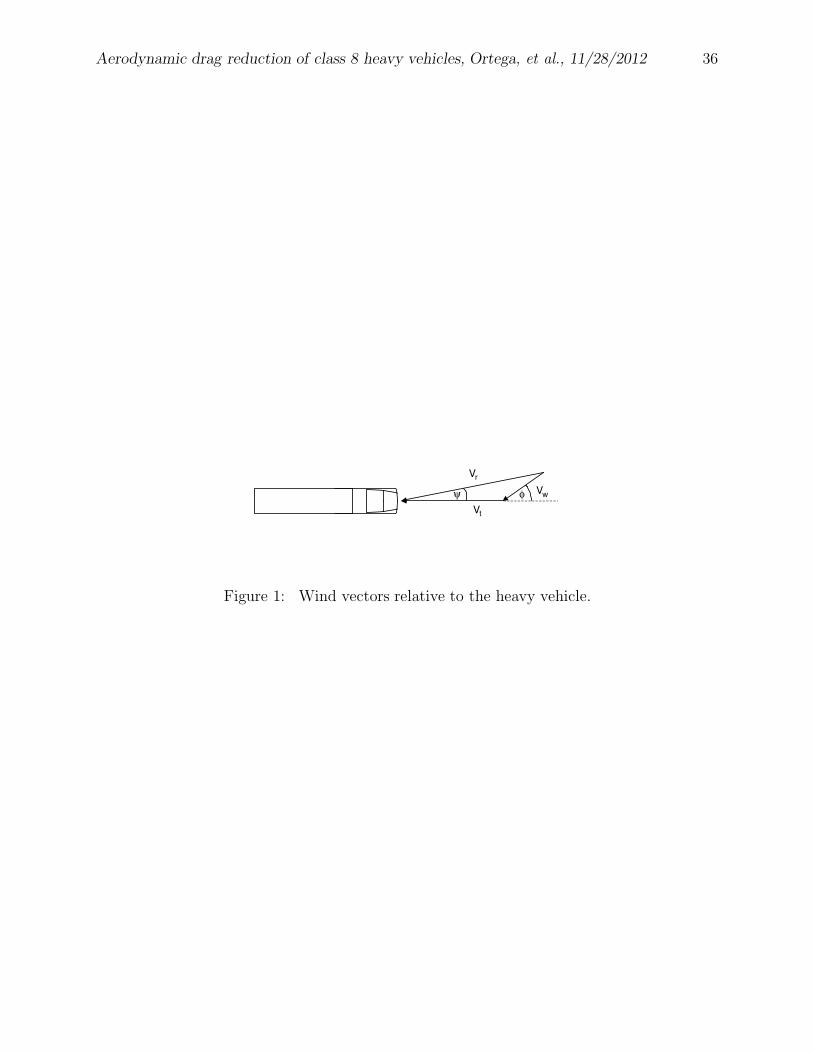
Assume that a vehicle is traveling at a velocity Vt with respect to the roadway and there
is a crosswind that has a velocity Vw at the mid-height of the vehicle acting at an angle φ
with respect to Vt (Fig. 1). The total speed of the wind relative to the vehicle is given by
Vr = Vt
√
1 + 2(Vw/Vt) cos φ+ (Vw/Vt)2 (1)
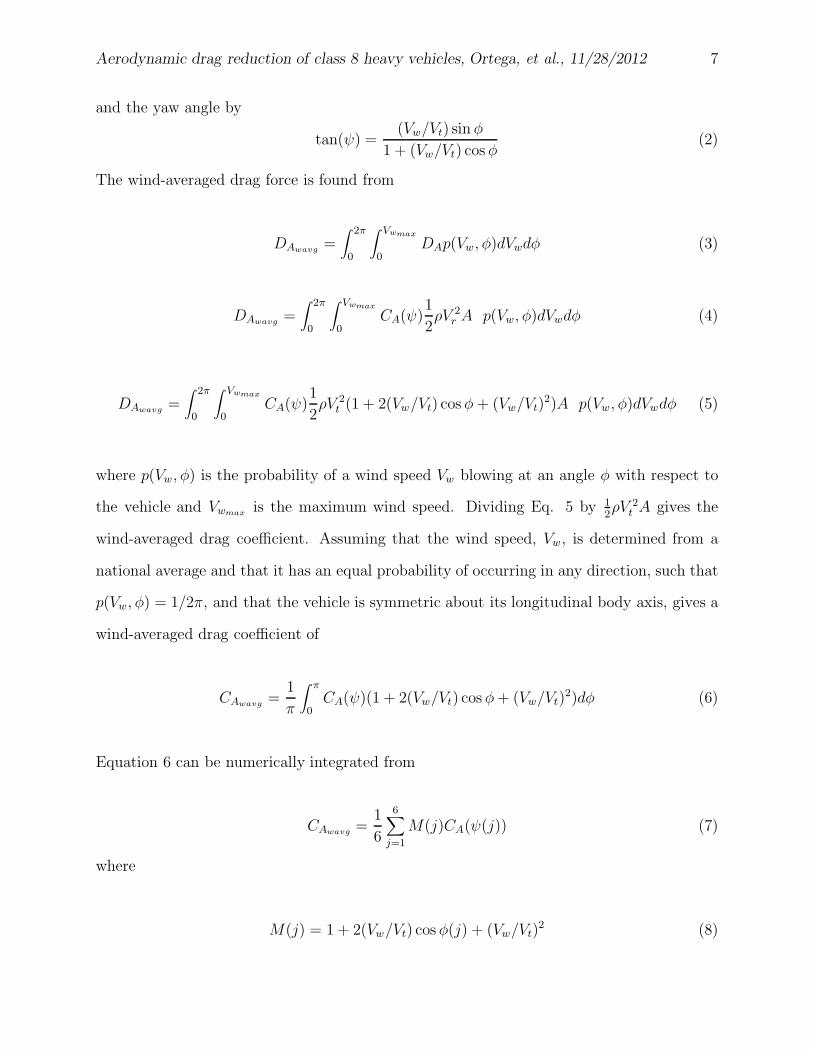
Aerodynamic drag reduction of class 8 heavy vehicles, Ortega, et al., 11/28/2012 7
and the yaw angle by
tan(ψ) =(Vw/Vt) sin φ
1 + (Vw/Vt) cos φ(2)
The wind-averaged drag force is found from
DAwavg=
∫
2π
0
∫ Vwmax
0
DAp(Vw, φ)dVwdφ (3)
DAwavg=
∫
2π
0
∫ Vwmax
0
CA(ψ)1
2ρV 2
r A p(Vw, φ)dVwdφ (4)
DAwavg=
∫
2π
0
∫ Vwmax
0
CA(ψ)1
2ρV 2
t (1 + 2(Vw/Vt) cos φ+ (Vw/Vt)2)A p(Vw, φ)dVwdφ (5)
where p(Vw, φ) is the probability of a wind speed Vw blowing at an angle φ with respect to
the vehicle and Vwmaxis the maximum wind speed. Dividing Eq. 5 by 1
2ρV 2
t A gives the
wind-averaged drag coefficient. Assuming that the wind speed, Vw, is determined from a
national average and that it has an equal probability of occurring in any direction, such that
p(Vw, φ) = 1/2π, and that the vehicle is symmetric about its longitudinal body axis, gives a
wind-averaged drag coefficient of
CAwavg=
1
π
∫ π
0
CA(ψ)(1 + 2(Vw/Vt) cos φ+ (Vw/Vt)2)dφ (6)
Equation 6 can be numerically integrated from
CAwavg=
1
6
6∑
j=1
M(j)CA(ψ(j)) (7)
where
M(j) = 1 + 2(Vw/Vt) cos φ(j) + (Vw/Vt)2 (8)
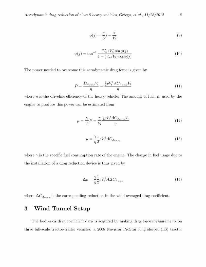
Aerodynamic drag reduction of class 8 heavy vehicles, Ortega, et al., 11/28/2012 8
φ(j) =π
6j −
π
12(9)
ψ(j) = tan−1(Vw/Vt) sinφ(j)
1 + (Vw/Vt) cosφ(j)(10)
The power needed to overcome this aerodynamic drag force is given by
P =DAwavg
Vt
η=
1
2ρV 2
t ACAwavgVt
η(11)
where η is the driveline efficiency of the heavy vehicle. The amount of fuel, µ, used by the
engine to produce this power can be estimated from
µ =γ
Vt
P =γ
Vt
1
2ρV 2
t ACAwavgVt
η(12)
µ =γ
η
1
2ρV 2
t ACAwavg(13)
where γ is the specific fuel consumption rate of the engine. The change in fuel usage due to
the installation of a drag reduction device is thus given by
∆µ =γ
η
1
2ρV 2
t A∆CAwavg(14)
where ∆CAwavgis the corresponding reduction in the wind-averaged drag coefficient.
3 Wind Tunnel Setup
The body-axis drag coefficient data is acquired by making drag force measurements on
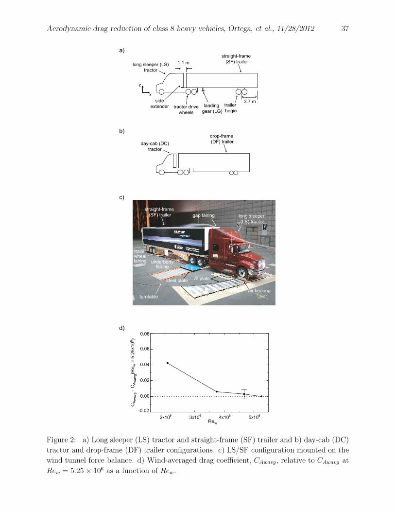
three full-scale tractor-trailer vehicles: a 2008 Navistar ProStar long sleeper (LS) tractor
Aerodynamic drag reduction of class 8 heavy vehicles, Ortega, et al., 11/28/2012 9
with a Wabash 16.2 m straight-frame (SF), dry freight trailer; a 2008 Navistar ProStar day-
cab (DC) tractor with the SF trailer; and the DC tractor with a Kentucky Trailer 16.2 m
drop-frame (DF), dry freight trailer (Fig. 2a-c). These vehicles have overall lengths ranging
from 20 to 22 m and cross-sectional areas of 10.5 m2, 10.5 m2, and 10.6 m2, respectively. The
gap between the tractor and trailer is set to 1.1 m for each baseline vehicle configuration and
the trailer bogie on the SF trailer is positioned such that the midpoint between the trailer
wheels is 3.7 m from the trailer base. The measurements are made within the NASA Ames
80×120 wind tunnel, which has a contraction ratio of 5:1 and a test section cross-section
of 24.4 m × 36.6 m. Aside from a few select runs at speeds as low as 8.9 m/s (20 mph)
and as high as 35.8 m/s (80 mph), the nominal tunnel speed is set to U◦ = 25.9 m/s (58
mph, dynamic pressure of 420 Pa) with a free-stream turbulence intensity of ≈ 1% [67].
The resulting Reynolds number, Rew = Uow/ν, based upon the trailer width, w = 2.6 m, is
4.6 × 10⁶, where ν is the kinematic viscosity of air. Although this tunnel speed is slightly
less than the typical highway speed in the United States (29.1 m/s or 65 mph), a series
of runs at various tunnel speeds shows that the wind-averaged drag coefficient is relatively
independent of Reynolds number by Rew = 4.6× 10⁶ (Fig. 2d). The front of each tractor is
positioned approximately one vehicle length downstream of the test section inlet. From the
measurements of Zell [67], the boundary layer displacement thickness is on the order of 10−1
m approximately 1 m and 3.0 m upstream of the LS and DC tractors, respectively, within
the empty tunnel. When the vehicles are yawed about the z-axis to the maximum extent
of 15◦ relative to the free-stream velocity, the blockage within the test section is only ≈ 3%
and, therefore, no blockage corrections are applied to the drag measurements.
The heavy vehicle is supported by a system similar to that of Cooper & Leuschen [15]
and Leuschen & Cooper [32], which permits the vehicle to partially rest upon the tunnel
and turntable floor, while still transmitting the drag force to the balance (Fig. 2c). This
is accomplished by placing aluminum plates beneath the tractor steering wheels and trailer
Aerodynamic drag reduction of class 8 heavy vehicles, Ortega, et al., 11/28/2012 10
wheels and resting these wheels upon air bearings, which receive a continuous air supply from
the wind tunnel facility. When the air bearings are inflated, the bottom of the tires is about
0.15 m above the tunnel floor, placing them at the approximate height of the boundary layer
displacement thickness at the front of the vehicle. The tractor drive wheels are chocked and
strapped to a steel plate that is fixed to the balance. The low friction coefficient provided
by the air bearings thus makes it possible to transmit not only the drag force, but also the
side force and the yawing moment to the balance through the tractor drive wheels. Since
the steering wheels of the LS tractor extend beyond the edge of the turntable onto the
tunnel floor, the aluminum plate beneath these wheels must be large enough to allow the
air bearings to remain on the plate as the vehicle is yawed. For the shorter DC tractor,
the steering wheels remain on turntable and, as a result, much smaller aluminum plates
are employed beneath these wheels. The same approach is used for the trailer wheels that
are located on the turntable. Although the tractor and trailer remain rigid relative to one
another through the use of turnbuckles and chains, flexure of the entire vehicle does occur
relative to the steel plate supporting the tractor wheels as a result of the compliant the
tractor tires. Depending on the location of the center of pressure on the vehicle, rotation
about the steel plate can alter the vehicle yaw angle by as much as 1◦. To account for this
non-negligible amount of rotation, a photo-electric proximity sensor (SICK DT 10-P10B5
accurate to ±0.006 m) and optical target are placed on the aluminum trailer wheel plate and
trailer wheel air bearing, respectively. Using the proximity sensor and turntable yaw angle
data, the actual yaw angle of the vehicle is then calculated.
The external balance system used to measure the drag force has a range of ±2.224× 10⁵
N with an accuracy of ±53 N over this entire range. However, only a small fraction (≈2%) of
this range is utilized for the vehicle drag. To determine the balance accuracy over this much
smaller range, check loads are applied to the installed vehicle by hanging known weights on a
pulley system with a load cell (Dillon ED Xtreme, 11120 N capacity) accurate to within ±2.2
Aerodynamic drag reduction of class 8 heavy vehicles, Ortega, et al., 11/28/2012 11
N. The resulting drag force measurement accuracy is found to be ±44N, which is the same
as that of a previous heavy vehicle study using this same balance [31]. Thus for the present
study, we take the drag force accuracy of the balance to be ±44 N. Due to the fact that the
vehicles span both the metric and non-metric portions of the balance system through the
air bearings, it is also necessary to assess the drag force measurement error incurred by this
aspect of the setup. This is accomplished by recording the drag force on the vehicle when
it is rotated through a yaw sweep during a wind-off condition. For a perfectly rigid vehicle,
balance system, air bearings, and tunnel floor and for completely frictionless air bearings,
the resulting drag force should equal zero for all yaw angles. However, the results of this
exercise demonstrate drag force errors of ±58 N, ±19 N, and ±23 N for the LS/SF, DC/SF,
and DC/DF configurations, respectively. Note that the LS/SF configuration has the largest
error as a result of the steering wheel air bearings having to sweep across the surface of the
aluminum plate, while those of the DC/SF and DC/DF configurations remain stationary
relative to the smaller aluminum plates beneath the steering wheels.
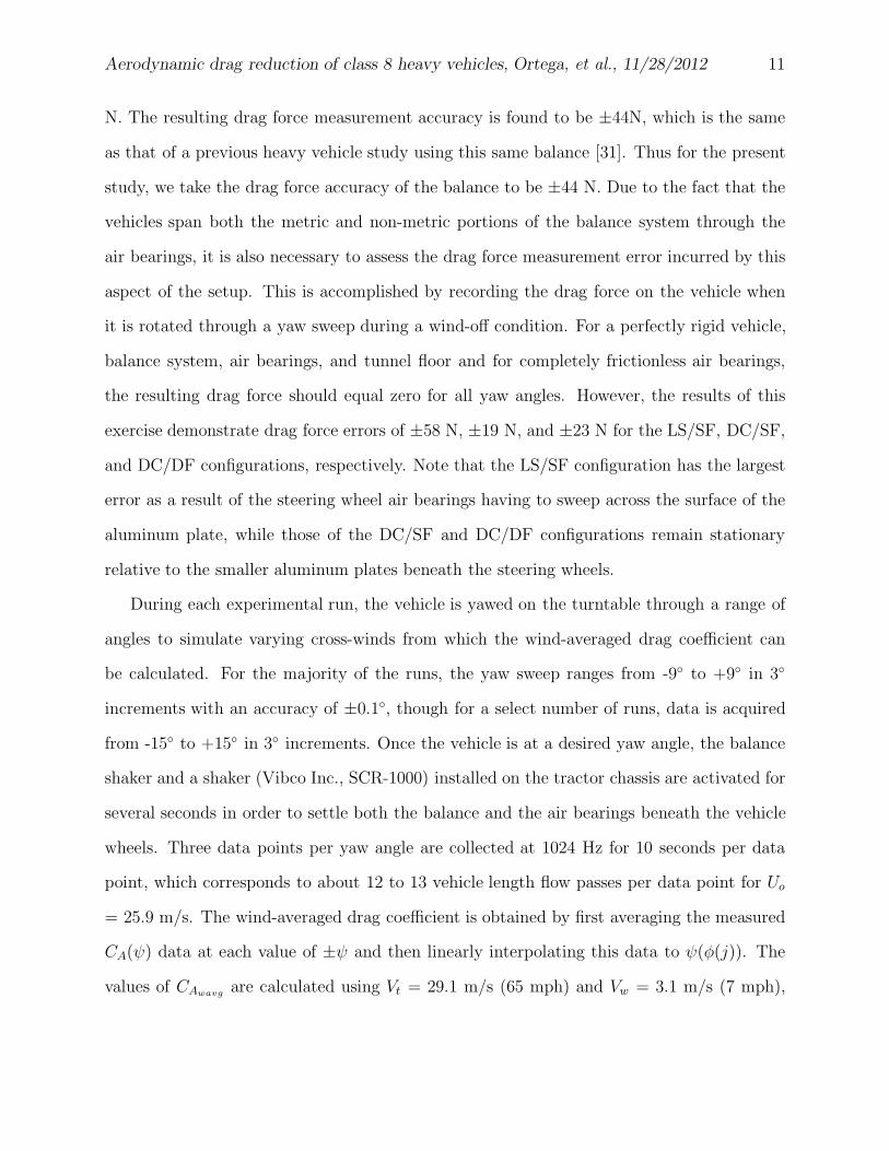
During each experimental run, the vehicle is yawed on the turntable through a range of
angles to simulate varying cross-winds from which the wind-averaged drag coefficient can
be calculated. For the majority of the runs, the yaw sweep ranges from -9◦ to +9◦ in 3◦
increments with an accuracy of ±0.1◦, though for a select number of runs, data is acquired
from -15◦ to +15◦ in 3◦ increments. Once the vehicle is at a desired yaw angle, the balance
shaker and a shaker (Vibco Inc., SCR-1000) installed on the tractor chassis are activated for
several seconds in order to settle both the balance and the air bearings beneath the vehicle
wheels. Three data points per yaw angle are collected at 1024 Hz for 10 seconds per data
point, which corresponds to about 12 to 13 vehicle length flow passes per data point for Uo
= 25.9 m/s. The wind-averaged drag coefficient is obtained by first averaging the measured
CA(ψ) data at each value of ±ψ and then linearly interpolating this data to ψ(φ(j)). The
values of CAwavgare calculated using Vt = 29.1 m/s (65 mph) and Vw = 3.1 m/s (7 mph),
Aerodynamic drag reduction of class 8 heavy vehicles, Ortega, et al., 11/28/2012 12
where 3.1 m/s is the national-average wind speed in the United States at 2.1 m above the
ground [5], and the resulting savings in the estimated fuel usage (Eq. 14) using ρ = 1.23
kg/m3, η = 0.85, and γ = 7.639 × 10⁻⁸ L/W·s [5, 8, 9, 32]. Performing an uncertainty
analysis [20] that takes into account the accuracy of the measurement systems, the drag
force errors due to the air bearing setup, and the repeatability of the force measurements
shows that the resulting errors in CAwavgare ±0.006, ±0.005, and ±0.004 for the LS/SF,
DC/SF, and DC/DF configurations, respectively. The 10 second sample time is shown to
be adequate since increasing it to 20 seconds produces a change in the computed wind-
averaged drag coefficient that is smaller than the measurement error. In addition, the effects
of flow hysteresis are shown to be negligible on CAwavgwhen the direction of the yaw sweep
is reversed. Since the steel plate and supporting hardware immediately beneath the tractor
drive wheels protrude approximately 0.1 m into the boundary layer flow above the tunnel
floor, they contribute an additional drag force to the balance system during a wind-on
condition, resulting in a larger value of CAwavg. Measurements made without a vehicle
installed on the balance reveal that this force is on the order of 160 N. Due to the non-linear
interactions of the boundary layer flow between the vehicle underside and the steel plate and
supporting hardware, this force is not necessarily the same when the vehicle is installed on
the balance and therefore it cannot simply be subtracted from the measured drag force. It is
assumed that this force does not change significantly as drag reduction devices are installed
since the devices typically reside rather far from the steel plate and supporting hardware.
Therefore, no attempt is made to correct for this additional force in the present study.
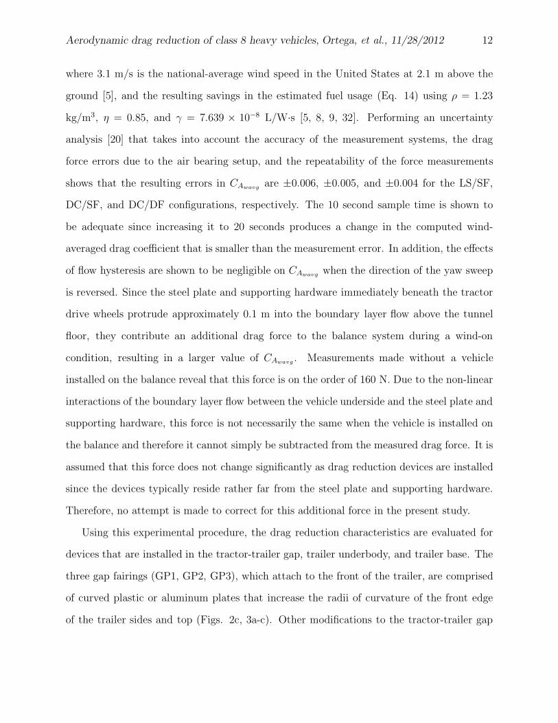
Using this experimental procedure, the drag reduction characteristics are evaluated for
devices that are installed in the tractor-trailer gap, trailer underbody, and trailer base. The
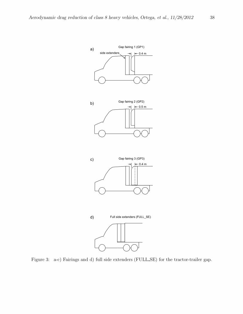
three gap fairings (GP1, GP2, GP3), which attach to the front of the trailer, are comprised
of curved plastic or aluminum plates that increase the radii of curvature of the front edge
of the trailer sides and top (Figs. 2c, 3a-c). Other modifications to the tractor-trailer gap
Aerodynamic drag reduction of class 8 heavy vehicles, Ortega, et al., 11/28/2012 13
include reducing the distance between the back of the tractor to the front of the trailer from
1.1 m to 0.61 m (0.61m gap), installing revised side extenders (REV SE) that flare slightly
outboard in order to accommodate the smaller tractor-trailer gap on the LS tractor, and
filling the gap between the DC side extenders and the trailer front with aluminum sheets
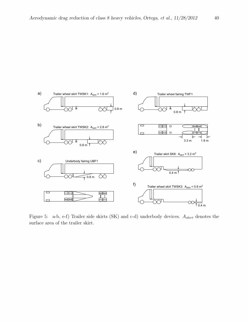
(FULL SE)(Fig. 3d). The devices installed on the trailer underbody are various trailer
skirts (SK#), a prototype fairing (UBF1), and trailer wheel fairings (TWF1), the last of
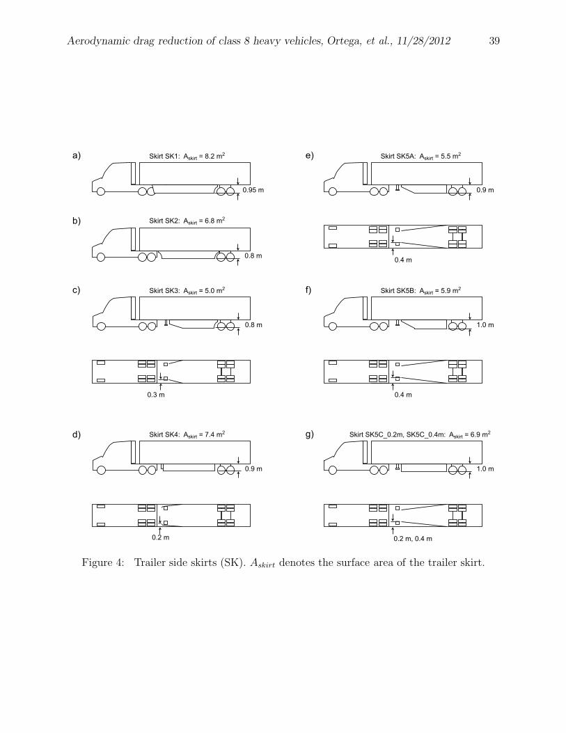
which are qualitatively similar to those in [5] (Figs. 4-5). For one trailer skirt design (SK5),
adjustments are made to both the trailer skirt area and the angle of the skirt relative to the
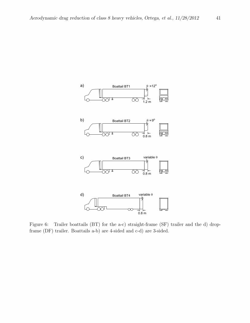
trailer side (Fig. 4e-g). Lastly, four boattails are installed on the trailer bases of various
vehicle configurations (Fig. 6). While the boattails BT1 and BT2 have fixed angles, θ,
relative to the trailer, boattails BT3 and BT4 are designed to have variable deflection angles
on the top and side boattail plates in order to determine an optimum angle setting. Since
the plates used in the construction of these boattails are not perfectly flat, the measurement
of the deflection angle is accurate to within only ±2◦.
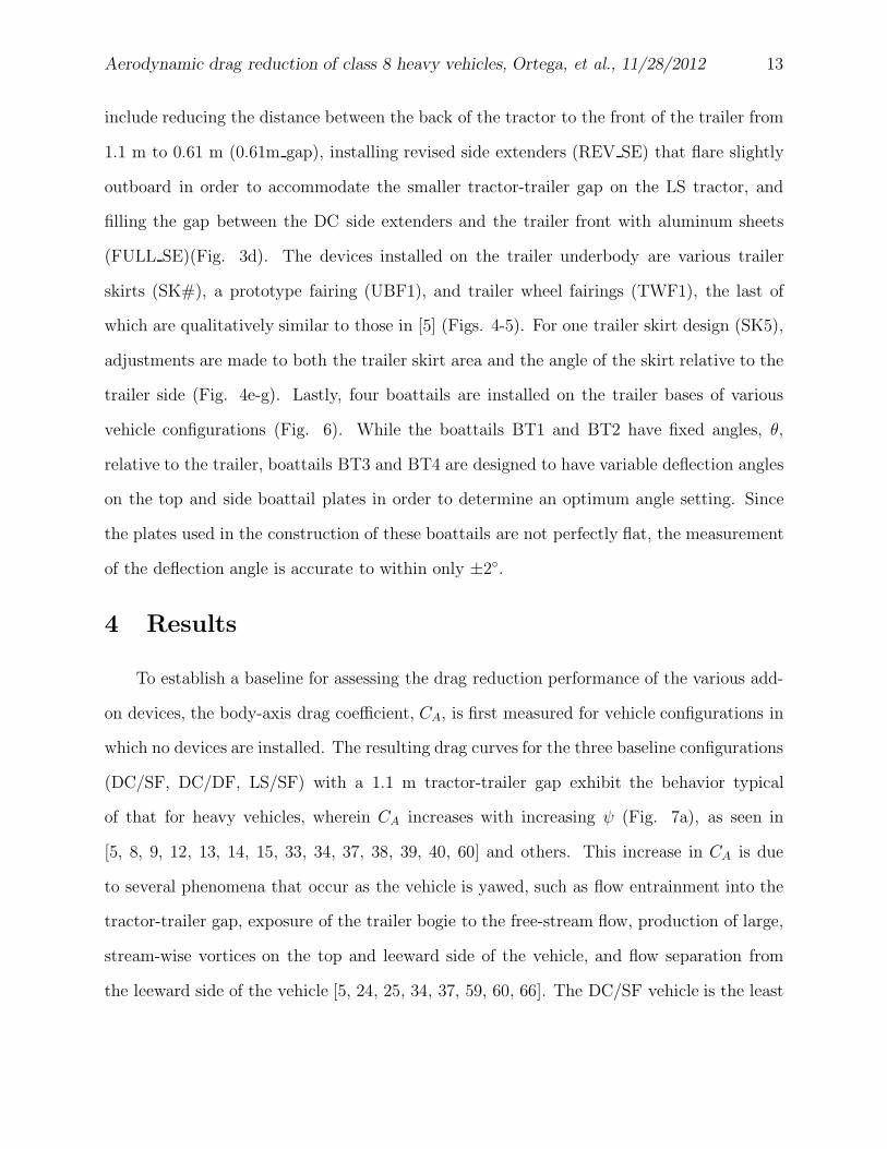
4 Results
To establish a baseline for assessing the drag reduction performance of the various add-
on devices, the body-axis drag coefficient, CA, is first measured for vehicle configurations in
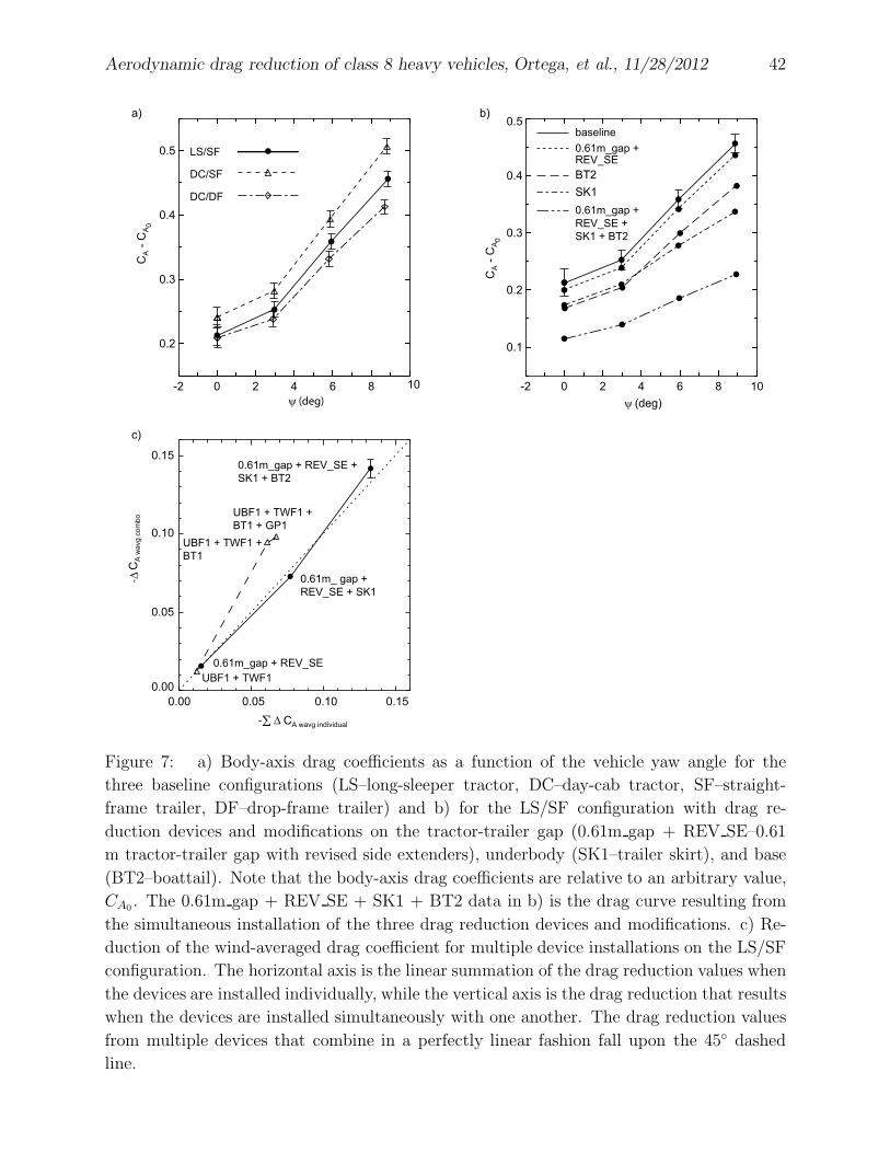
which no devices are installed. The resulting drag curves for the three baseline configurations
(DC/SF, DC/DF, LS/SF) with a 1.1 m tractor-trailer gap exhibit the behavior typical
of that for heavy vehicles, wherein CA increases with increasing ψ (Fig. 7a), as seen in
[5, 8, 9, 12, 13, 14, 15, 33, 34, 37, 38, 39, 40, 60] and others. This increase in CA is due
to several phenomena that occur as the vehicle is yawed, such as flow entrainment into the
tractor-trailer gap, exposure of the trailer bogie to the free-stream flow, production of large,
stream-wise vortices on the top and leeward side of the vehicle, and flow separation from
the leeward side of the vehicle [5, 24, 25, 34, 37, 59, 60, 66]. The DC/SF vehicle is the least
Aerodynamic drag reduction of class 8 heavy vehicles, Ortega, et al., 11/28/2012 14
aerodynamic of these configurations due to a combination of the steeper angle of the roof
aero-shield and the exposed trailer bogie on the straight-frame trailer. However, pairing the
DC tractor with the DF trailer significantly reduces the trailer underbody flow, producing a
vehicle that has the least aerodynamic drag of the three baseline configurations.
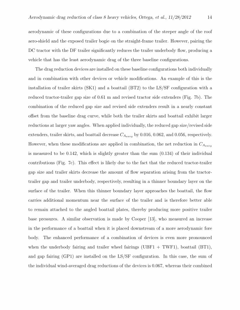
The drag reduction devices are installed on these baseline configurations both individually
and in combination with other devices or vehicle modifications. An example of this is the
installation of trailer skirts (SK1) and a boattail (BT2) to the LS/SF configuration with a
reduced tractor-trailer gap size of 0.61 m and revised tractor side extenders (Fig. 7b). The
combination of the reduced gap size and revised side extenders result in a nearly constant
offset from the baseline drag curve, while both the trailer skirts and boattail exhibit larger
reductions at larger yaw angles. When applied individually, the reduced gap size/revised side
extenders, trailer skirts, and boattail decrease CAwavgby 0.016, 0.062, and 0.056, respectively.
However, when these modifications are applied in combination, the net reduction in CAwavg
is measured to be 0.142, which is slightly greater than the sum (0.134) of their individual
contributions (Fig. 7c). This effect is likely due to the fact that the reduced tractor-trailer
gap size and trailer skirts decrease the amount of flow separation arising from the tractor-
trailer gap and trailer underbody, respectively, resulting in a thinner boundary layer on the
surface of the trailer. When this thinner boundary layer approaches the boattail, the flow
carries additional momentum near the surface of the trailer and is therefore better able
to remain attached to the angled boattail plates, thereby producing more positive trailer
base pressures. A similar observation is made by Cooper [13], who measured an increase
in the performance of a boattail when it is placed downstream of a more aerodynamic fore
body. The enhanced performance of a combination of devices is even more pronounced
when the underbody fairing and trailer wheel fairings (UBF1 + TWF1), boattail (BT1),
and gap fairing (GP1) are installed on the LS/SF configuration. In this case, the sum of
the individual wind-averaged drag reductions of the devices is 0.067, whereas their combined
Aerodynamic drag reduction of class 8 heavy vehicles, Ortega, et al., 11/28/2012 15
reduction is 0.098. The majority of this non-linear behavior is due to a favorable interaction
between the boattail and the trailer underbody fairing and trailer wheel fairings (Fig. 7c).
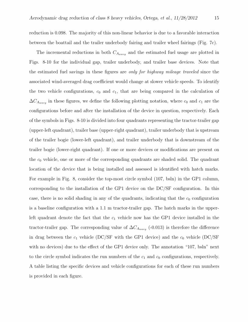
The incremental reductions in both CAwavgand the estimated fuel usage are plotted in
Figs. 8-10 for the individual gap, trailer underbody, and trailer base devices. Note that
the estimated fuel savings in these figures are only for highway mileage traveled since the
associated wind-averaged drag coefficient would change at slower vehicle speeds. To identify
the two vehicle configurations, c0 and c1, that are being compared in the calculation of
∆CAwavgin these figures, we define the following plotting notation, where c0 and c1 are the
configurations before and after the installation of the device in question, respectively. Each
of the symbols in Figs. 8-10 is divided into four quadrants representing the tractor-trailer gap
(upper-left quadrant), trailer base (upper-right quadrant), trailer underbody that is upstream
of the trailer bogie (lower-left quadrant), and trailer underbody that is downstream of the
trailer bogie (lower-right quadrant). If one or more devices or modifications are present on
the c0 vehicle, one or more of the corresponding quadrants are shaded solid. The quadrant
location of the device that is being installed and assessed is identified with hatch marks.
For example in Fig. 8, consider the top-most circle symbol (107, bsln) in the GP1 column,
corresponding to the installation of the GP1 device on the DC/SF configuration. In this
case, there is no solid shading in any of the quadrants, indicating that the c0 configuration
is a baseline configuration with a 1.1 m tractor-trailer gap. The hatch marks in the upper-
left quadrant denote the fact that the c1 vehicle now has the GP1 device installed in the
tractor-trailer gap. The corresponding value of ∆CAwavg(-0.013) is therefore the difference
in drag between the c1 vehicle (DC/SF with the GP1 device) and the c0 vehicle (DC/SF
with no devices) due to the effect of the GP1 device only. The annotation “107, bsln” next
to the circle symbol indicates the run numbers of the c1 and c0 configurations, respectively.
A table listing the specific devices and vehicle configurations for each of these run numbers
is provided in each figure.
Aerodynamic drag reduction of class 8 heavy vehicles, Ortega, et al., 11/28/2012 16
4.1 Tractor-Trailer Gap Devices
The reductions in CAwavgand the estimated fuel usage for the gap devices and modi-
fications are plotted in Fig. 8. The best performing gap device/modification occurs when
the tractor-trailer gap of the baseline DC/SF configuration is decreased from 1.1 m to 0.61
m. This leads to a reduction in CAwavgof 0.021 and an estimated fuel savings of about 2100
L/2.012×108 m hwy, which is comparable to the scaled wind tunnel results of Cooper [11]
for a reduced tractor-trailer gap size (see Table 1). Performing the same modification to
the LS/SF configuration (93, bsln) along with the installation of the revised side extenders
yields a smaller (0.016) reduction in CAwavg, which is likely due to the fact that the more
streamlined LS/SF has less cross-stream flow in the tractor-trailer gap to begin with than
that of the DC/SF.
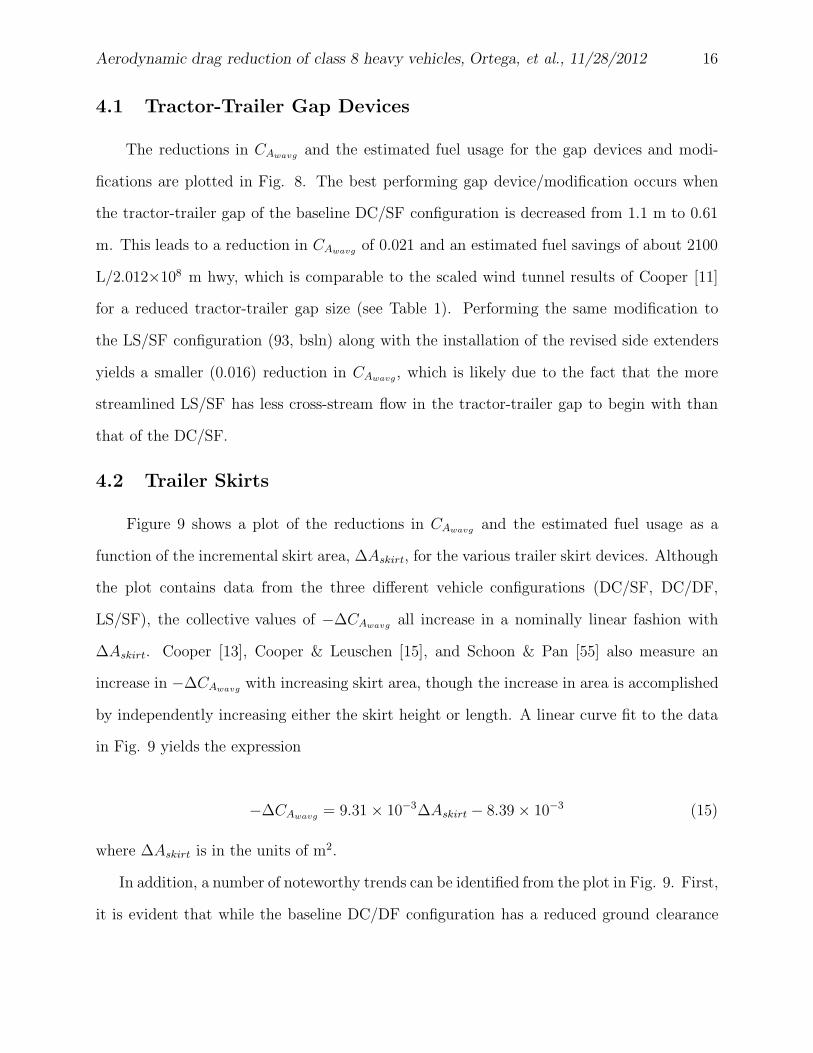
4.2 Trailer Skirts
Figure 9 shows a plot of the reductions in CAwavgand the estimated fuel usage as a
function of the incremental skirt area, ∆Askirt, for the various trailer skirt devices. Although
the plot contains data from the three different vehicle configurations (DC/SF, DC/DF,
LS/SF), the collective values of −∆CAwavgall increase in a nominally linear fashion with
∆Askirt. Cooper [13], Cooper & Leuschen [15], and Schoon & Pan [55] also measure an
increase in −∆CAwavgwith increasing skirt area, though the increase in area is accomplished
by independently increasing either the skirt height or length. A linear curve fit to the data
in Fig. 9 yields the expression
−∆CAwavg= 9.31 × 10⁻³∆Askirt − 8.39 × 10⁻³ (15)
where ∆Askirt is in the units of m2.
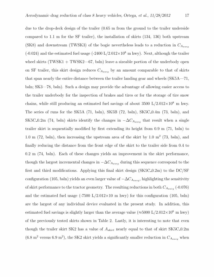
In addition, a number of noteworthy trends can be identified from the plot in Fig. 9. First,
it is evident that while the baseline DC/DF configuration has a reduced ground clearance
Aerodynamic drag reduction of class 8 heavy vehicles, Ortega, et al., 11/28/2012 17
due to the drop-deck design of the trailer (0.65 m from the ground to the trailer underside
compared to 1.1 m for the SF trailer), the installation of skirts (134, 136) both upstream
(SK8) and downstream (TWSK3) of the bogie nevertheless leads to a reduction in CAwavg
(-0.024) and the estimated fuel usage (-2400 L/2.012×108 m hwy). Next, although the trailer
wheel skirts (TWSK1 + TWSK2—67, bsln) leave a sizeable portion of the underbody open
on SF trailer, this skirt design reduces CAwavgby an amount comparable to that of skirts
that span nearly the entire distance between the trailer landing gear and wheels (SK5A—71,
bsln; SK3—78, bsln). Such a design may provide the advantage of allowing easier access to
the trailer underbody for the inspection of brakes and tires or for the storage of tire snow
chains, while still producing an estimated fuel savings of about 3500 L/2.012×108 m hwy.
The series of runs for the SK5A (71, bsln), SK5B (72, bsln), SK5C 0.4m (73, bsln), and
SK5C 0.2m (74, bsln) skirts identify the changes in −∆CAwavgthat result when a single
trailer skirt is sequentially modified by first extending its height from 0.9 m (71, bsln) to
1.0 m (72, bsln), then increasing the upstream area of the skirt by 1.0 m2 (73, bsln), and
finally reducing the distance from the front edge of the skirt to the trailer side from 0.4 to
0.2 m (74, bsln). Each of these changes yields an improvement in the skirt performance,
though the largest incremental changes in −∆CAwavgduring this sequence correspond to the
first and third modifications. Applying this final skirt design (SK5C 0.2m) to the DC/SF
configuration (105, bsln) yields an even larger value of −∆CAwavg, highlighting the sensitivity
of skirt performance to the tractor geometry. The resulting reductions in both CAwavg(-0.076)
and the estimated fuel usage (-7500 L/2.012×10 m hwy) for this configuration (105, bsln)
are the largest of any individual device evaluated in the present study. In addition, this
estimated fuel savings is slightly larger than the average value (≈5000 L/2.012×108 m hwy)
of the previously tested skirts shown in Table 2. Lastly, it is interesting to note that even
though the trailer skirt SK2 has a value of Askirt nearly equal to that of skirt SK5C 0.2m
(6.8 m2 versus 6.9 m2), the SK2 skirt yields a significantly smaller reduction in CAwavgwhen
Aerodynamic drag reduction of class 8 heavy vehicles, Ortega, et al., 11/28/2012 18
a performance comparison is made on the DC/SF configuration (105, bsln versus 119, bsln).
The primary differences between these two skirts is that the SK5C 0.2m skirt is angled
relative to the trailer side and has a height of 1.0 m, while the SK2 skirt is parallel to the
trailer side and has a height of 0.8 m. This once again demonstrates that slight variations
in design can yield substantial changes to the skirt performance, which in this case lead to a
difference in the estimated fuel savings of approximately 3000 L/2.012×108 m hwy between
the two skirts.
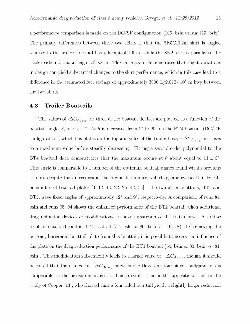
4.3 Trailer Boattails
The values of -∆CAwavgfor three of the boattail devices are plotted as a function of the
boattail angle, θ, in Fig. 10. As θ is increased from 0◦ to 20◦ on the BT4 boattail (DC/DF
configuration), which has plates on the top and sides of the trailer base, −∆CAwavgincreases
to a maximum value before steadily decreasing. Fitting a second-order polynomial to the
BT4 boattail data demonstrates that the maximum occurs at θ about equal to 11 ± 2◦.
This angle is comparable to a number of the optimum boattail angles found within previous
studies, despite the differences in the Reynolds number, vehicle geometry, boattail length,
or number of boattail plates [3, 12, 13, 22, 26, 42, 55]. The two other boattails, BT1 and
BT2, have fixed angles of approximately 12◦ and 9◦, respectively. A comparison of runs 84,
bsln and runs 95, 94 shows the enhanced performance of the BT2 boattail when additional
drag reduction devices or modifications are made upstream of the trailer base. A similar
result is observed for the BT1 boattail (54, bsln or 80, bsln vs. 79, 78). By removing the
bottom, horizontal boattail plate from this boattail, it is possible to assess the influence of
the plate on the drag reduction performance of the BT1 boattail (54, bsln or 80, bsln vs. 81,
bsln). This modification subsequently leads to a larger value of −∆CAwavg, though it should
be noted that the change in −∆CAwavgbetween the three and four-sided configurations is
comparable to the measurement error. This possible trend is the opposite to that in the
study of Cooper [13], who showed that a four-sided boattail yields a slightly larger reduction
Aerodynamic drag reduction of class 8 heavy vehicles, Ortega, et al., 11/28/2012 19
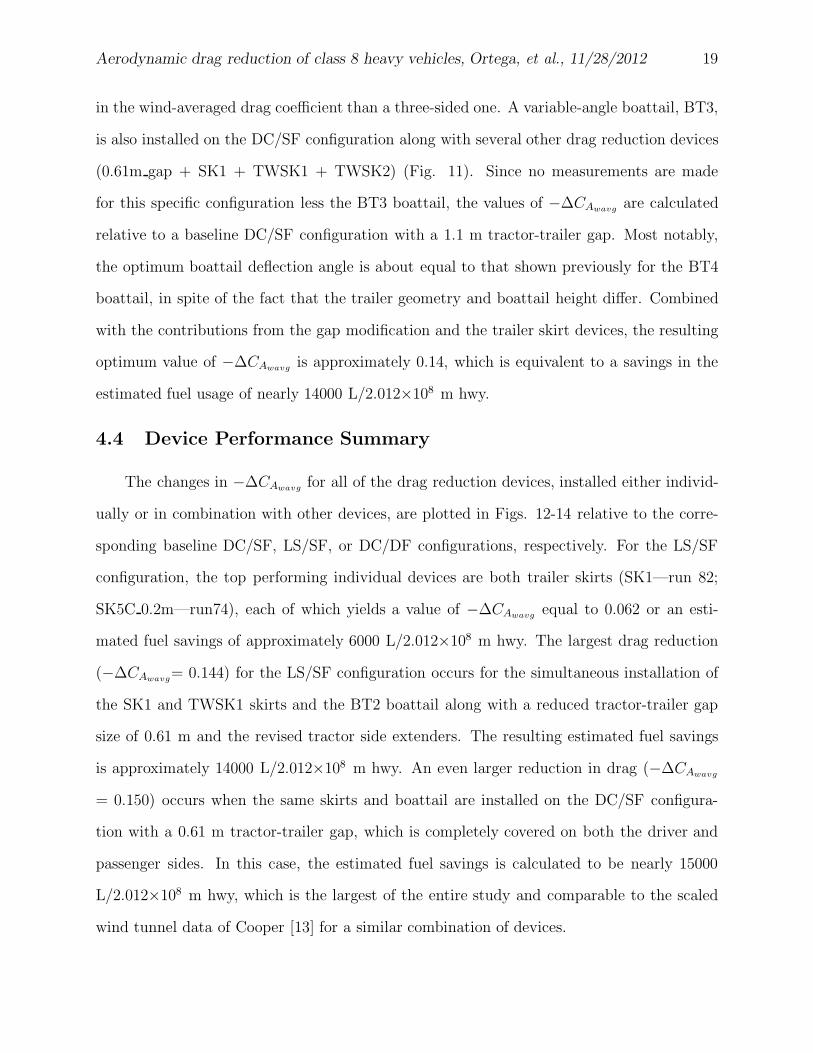
in the wind-averaged drag coefficient than a three-sided one. A variable-angle boattail, BT3,
is also installed on the DC/SF configuration along with several other drag reduction devices
(0.61m gap + SK1 + TWSK1 + TWSK2) (Fig. 11). Since no measurements are made
for this specific configuration less the BT3 boattail, the values of −∆CAwavgare calculated
relative to a baseline DC/SF configuration with a 1.1 m tractor-trailer gap. Most notably,
the optimum boattail deflection angle is about equal to that shown previously for the BT4
boattail, in spite of the fact that the trailer geometry and boattail height differ. Combined
with the contributions from the gap modification and the trailer skirt devices, the resulting
optimum value of −∆CAwavgis approximately 0.14, which is equivalent to a savings in the
estimated fuel usage of nearly 14000 L/2.012×108 m hwy.
4.4 Device Performance Summary
The changes in −∆CAwavgfor all of the drag reduction devices, installed either individ-
ually or in combination with other devices, are plotted in Figs. 12-14 relative to the corre-
sponding baseline DC/SF, LS/SF, or DC/DF configurations, respectively. For the LS/SF
configuration, the top performing individual devices are both trailer skirts (SK1—run 82;
SK5C 0.2m—run74), each of which yields a value of −∆CAwavgequal to 0.062 or an esti-
mated fuel savings of approximately 6000 L/2.012×108 m hwy. The largest drag reduction
(−∆CAwavg= 0.144) for the LS/SF configuration occurs for the simultaneous installation of
the SK1 and TWSK1 skirts and the BT2 boattail along with a reduced tractor-trailer gap
size of 0.61 m and the revised tractor side extenders. The resulting estimated fuel savings
is approximately 14000 L/2.012×108 m hwy. An even larger reduction in drag (−∆CAwavg
= 0.150) occurs when the same skirts and boattail are installed on the DC/SF configura-
tion with a 0.61 m tractor-trailer gap, which is completely covered on both the driver and
passenger sides. In this case, the estimated fuel savings is calculated to be nearly 15000
L/2.012×108 m hwy, which is the largest of the entire study and comparable to the scaled
wind tunnel data of Cooper [13] for a similar combination of devices.
Aerodynamic drag reduction of class 8 heavy vehicles, Ortega, et al., 11/28/2012 20
5 Discussion
While it is apparent that there is a great potential for fuel savings through the use of
aerodynamic drag reduction devices, the commercial fleet operators responsible for purchas-
ing them take into account a number of additional factors before they consider these devices
to be a truly viable means for cost savings. Therefore, in addition to the wind tunnel inves-
tigation, we conducted a survey from August to September 2010 of 256 small and large fleet
companies and owner/operater companies that operate class 8 heavy vehicles in the United
States (we define a small fleet as one in which there are at most 25 tractor-trailers and a
large fleet as one in which there are more than 26 tractor-trailers). A number of questions
are asked of these fleets to better understand their past experiences with drag reduction
devices, to determine the criteria and requirements the devices would have to meet in order
to have them installed throughout the majority of their fleets, and to further improve the
design of the devices. The feedback from this survey along with device performance data will
be essential as we move towards our goal of designing a trailer with factory-installed devices
that are both effective in reducing aerodynamic drag and acceptable by the fleet operators
who purchase them.
From the results of the survey, only 5% of the companies are currently using tractor-
trailer gap devices and trailer base devices, while 4% are using trailer skirts. However,
2-7% of the companies are planning to use these various devices in their operations and
another 27-30% would consider using them within the next 12 months to increase their fleet
fuel economy and reduce fuel costs. Most notably, the majority of the companies currently
using drag reduction devices observe an increase in vehicle fuel economy comparable to that
which was expected when the devices were purchased. Additional benefits that result from
the installation of these devices are reported to be improved vehicle handling under windy
conditions and a reduction in the amount of debris and water spray ejected by the vehicle,
the latter of which is similar to the findings of Weir et al. [66].
Aerodynamic drag reduction of class 8 heavy vehicles, Ortega, et al., 11/28/2012 21
In spite of these benefits, a number of shortcomings and challenges are identified with the
current drag reduction devices on the market. The purchase price is found to be the primary
barrier that prevents the adoption of these devices. About half of the companies are willing to
spend only $1000 or less on aerodynamic devices for each tractor-trailer combination, while
29% will spend only $500 or less. At the time of this survey, the former cost requirement
prevents all of the commercially available trailer skirts and base devices evaluated in the
80×120 wind tunnel from being viable options for nearly half of the companies surveyed.
In addition, the payback time for the devices is required to be 1 to 2 years for about half
of the companies and 3 years for another third of the companies. Second, the durability of
the devices is another shortcoming that must be met given that two-thirds of the companies
expect to spend only 5 hours or less per trailer each year for aerodynamic device maintenance.
And it is a lack of device durability, increased maintenance costs, vehicle downtime, and a lack
of device service stations for long-haul fleets that have often caused a number of companies to
discontinue the use of certain devices. Third, since a number of fleets operate their vehicles
up to a maximum load capacity, the weight of the devices can also prohibit the fleets from
employing them. In fact, about one-half of the surveyed companies are willing to add only 68
kg (149 lb) or less to their vehicles. Except for the gap devices, this requirement eliminates
nearly all of the commercially available trailer skirt and base devices evaluated in this study.
Lastly, the design of the device and its manner of deployment presents a challenge to the
fleets from both operational and cost standpoints. More than two-thirds of the companies
prefer that the aerodynamic devices deploy in a fully automatic fashion in order to eliminate
driver errors and to decrease the possibility of accidents or injuries. However, the convenience
of automatic deployment comes with additional device complexity, which reduces reliability
and increases the purchase price and maintenance time of the device. For about one-quarter
of the companies, this disadvantage is too costly and they would rather have their drivers
manually deploy devices that are simpler in construction and much easier to repair.
Aerodynamic drag reduction of class 8 heavy vehicles, Ortega, et al., 11/28/2012 22
These concerns and issues must first be addressed before aerodynamic drag reduction
devices can be accepted on a widespread basis throughout the United States. Both mass
production of devices and government tax breaks for fleets utilizing them can reduce the
purchase price barrier, making the devices affordable for a greater number of companies. To
provide device maintenance for long-haul trailers that are traveling cross-country, nation-
wide service centers that presently repair tires or tractors can be trained and equipped to
also repair aerodynamic devices. Furthermore, improved designs can minimize the weight
penalty of the devices and increase their durability. An example of the latter can be seen in
the evolution of trailer skirts, which originally had designs that were often constructed from
aluminum sheet metal. While aluminum is corrosion resistant and lightweight, it is unfor-
giving when flexed beyond a certain point. To remedy this shortcoming, a number of trailer
skirt manufacturers have started to use deformable, plastic panels that are attached to the
trailer underside in a manner that allows the skirt to flex without permanent deformation
when it contacts the ground.
The question of whether or not the devices should be manually or automatically deployed
remains to be answered. Perhaps, one solution is to integrate the device completely into the
trailer design, such that deployment is not even necessary. An example of this is seen in
the work of Schoon [54], wherein a prototype trailer is designed with an integrated boattail
shape along the last 0.61 m of the trailer. With the boattail constructed in a structural
manner similar to that of a standard trailer, it is robust enough to withstand operational
mishaps, such as accidental backing into a loading dock. The aerodynamic drag due to the
tractor-trailer gap can also be reduced with an automated fifth-wheel that is integrated into
the tractor. At highway speeds, where vehicle maneuvering is minimal, the fifth-wheel would
automatically decrease the distance between the tractor and trailer, while, below a certain
speed, the fifth wheel would increase this distance to allow for pivotal motion between the
tractor and trailer. Such a system would require no driver intervention, though it would
Aerodynamic drag reduction of class 8 heavy vehicles, Ortega, et al., 11/28/2012 23
need to be designed for both safe and reliable operation without significantly increasing the
cost of the tractor.
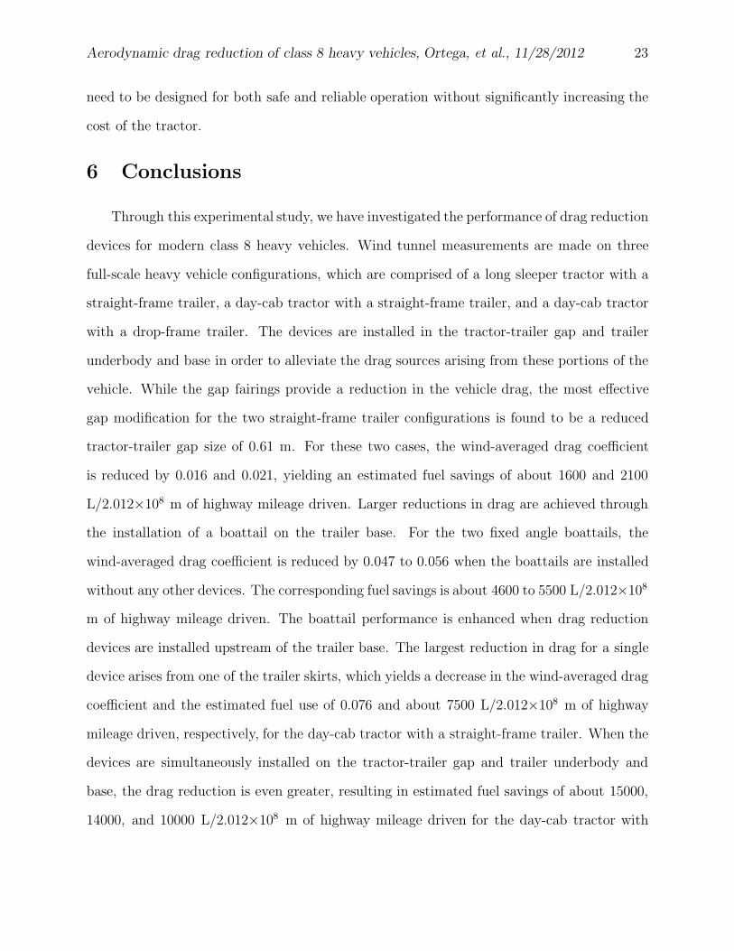
6 Conclusions
Through this experimental study, we have investigated the performance of drag reduction
devices for modern class 8 heavy vehicles. Wind tunnel measurements are made on three
full-scale heavy vehicle configurations, which are comprised of a long sleeper tractor with a
straight-frame trailer, a day-cab tractor with a straight-frame trailer, and a day-cab tractor
with a drop-frame trailer. The devices are installed in the tractor-trailer gap and trailer
underbody and base in order to alleviate the drag sources arising from these portions of the
vehicle. While the gap fairings provide a reduction in the vehicle drag, the most effective
gap modification for the two straight-frame trailer configurations is found to be a reduced
tractor-trailer gap size of 0.61 m. For these two cases, the wind-averaged drag coefficient
is reduced by 0.016 and 0.021, yielding an estimated fuel savings of about 1600 and 2100
L/2.012×108 m of highway mileage driven. Larger reductions in drag are achieved through
the installation of a boattail on the trailer base. For the two fixed angle boattails, the
wind-averaged drag coefficient is reduced by 0.047 to 0.056 when the boattails are installed
without any other devices. The corresponding fuel savings is about 4600 to 5500 L/2.012×108
m of highway mileage driven. The boattail performance is enhanced when drag reduction
devices are installed upstream of the trailer base. The largest reduction in drag for a single
device arises from one of the trailer skirts, which yields a decrease in the wind-averaged drag
coefficient and the estimated fuel use of 0.076 and about 7500 L/2.012×108 m of highway
mileage driven, respectively, for the day-cab tractor with a straight-frame trailer. When the
devices are simultaneously installed on the tractor-trailer gap and trailer underbody and
base, the drag reduction is even greater, resulting in estimated fuel savings of about 15000,
14000, and 10000 L/2.012×108 m of highway mileage driven for the day-cab tractor with
Aerodynamic drag reduction of class 8 heavy vehicles, Ortega, et al., 11/28/2012 24
the straight-frame trailer, the long sleeper tractor with the straight-frame trailer, and the
day-cab tractor with the drop-frame trailer, respectively.
While this study has successfully highlighted the aerodynamic performance of a wide
range of drag reduction devices, there are two important matters that remain to be deter-
mined at the present time. The first is the actual fuel savings provided by these devices
during normal operations. Since the data from this study has been acquired in a very con-
trolled environment, it may not be entirely representative of the flow fields that heavy vehicles
encounter when travelling on the road. For example, the wind tunnel does not produce the
freestream unsteadiness and turbulent length scales that arise from an environmental flow
and its interactions with roadside objects and nearby vehicles. In addition, the non-moving
ground plane beneath the vehicle produces a boundary layer that may underestimate the
performance of the trailer underbody devices. As has been observed in previous studies,
these types of effects can lead to differences between the estimated fuel savings from wind
tunnel data and that actually observed on the road [4, 5, 6, 16, 29, 50, 65]. To remedy this
potential shortcoming, future studies will include fuel economy data from both track testing
and subsequent fleet evaluations of select devices. The second matter that remains to be
determined is properly addressing the concerns raised by fleets regarding the drag reduc-
tion devices. From the results of the fleet survey, it is clearly evident that a number of the
devices evaluated within this study are simply unacceptable to the fleets due to numerous
economic, weight, and durability issues. As we move forward on this project, we will work
closely with our fleet and third-party device manufacturer team members to develop robust,
operationally-minded, and cost-effective solutions to these concerns. This process will pro-
vide a definitive path to implementing the drag reduction devices into future trailers, thereby
providing viable options for fleets seeking to improve the fuel economy of their heavy vehicle
operations.
Aerodynamic drag reduction of class 8 heavy vehicles, Ortega, et al., 11/28/2012 25
Acknowledgments
The authors would like to thank M. Betzina, C. Hartley, S. Lee, J. Sacco, and the
entire National Full-Scale Aerodynamics Complex team for their support during the wind
tunnel testing, J. Martinez and R. Flach of Texas A&M University for their wind tunnel
testing guidance and expertise, S. Baker, B. Hirschy, A. Spieth, and V. Swager of Navistar for
their mechanic support, E. Buckholtz, J. King, and S. LaMunyon of LLNL for their support
in device fabrication, the device manufacturers for loaning their gap fairings, trailer skirts,
and boattails, and F. Browand of the University of Southern California and P. Urbanczyk of
LLNL for their helpful feedback in the manuscript preparation. Lastly, the authors would
like to thank Lee Slezak of the Department of Energy Vehicle Technologies Program for his
programmatic support of this research effort. This work was performed under the auspices
of the US DOE by LLNL under contract DE-AC52-07NA27344.
References
[1] Annual Energy Outlook 2010 with Projections to 2035. 2010. DOE/EIA-0383(2010).
[2] Bachman, L.J., Erb, A., Bynum, C.L., 2005. Effect of single wide tires and trailer aero-
dynamics on fuel economy and NOx emissions of class 8 line-haul tractor-trailers. SAE
Paper 05CV-45.
[3] Browand, F., Radovich, C., Boivin, M., 2005. Fuel savings by means of flaps attached to
the base of a trailer: field test results. SAE Paper 2005-01-1016.
[4] Buckley, F.T., Jr., Marks, C.H., Walston, W.H., Jr., 1976. Analysis of coast down data
to assess aerodynamic drag reduction on full-scale tractor-trailer trucks in windy environ-
ments. SAE Trans. 85, 2756-2769.
[5] Buckley, F.T., Jr., Marks, C.H., Walston, W.H., Jr., 1978. A study of aerodynamic
methods for improving truck fuel economy. Final Report on National Science Foundation,
Aerodynamic drag reduction of class 8 heavy vehicles, Ortega, et al., 11/28/2012 26
Grant No. SIA-74-14843. Mechanical Engineering Department, University of Maryland,
College Park, MD.
[6] Buckley, F.T., Jr., Walston, W.H., Jr., Marks, C.H., 1978. Fuel savings from truck
aerodynamic drag reducers and correlation with wind-tunnel data. J. Energy 2(6), 321-329.
[7] Coon, J.D., Visser, K.D., 2004. Drag reduction of a tractor-trailer using planar boat tail
plates, in: McCallen, R., Browand, F., Ross, J., (Eds.), The Aerodynamics of Heavy Vehi-
cles: Trucks, Buses, and Trains, Lecture Notes in Applied and Computational Mechanics
19. Springer, Heidelberg, pp. 249-265.
[8] Cooper, K.R., 1976. A wind tunnel investigation into the fuel savings available from
the aerodynamic drag reduction of trucks. National Research Council Canada, Reprint of
article from DME/NAE Quarterly Bulletin, No. 1976(3).
[9] Cooper, K.R., 1978. Truck fuel savings through the use of trailer skirts and trailer rear-
corner rounding. National Research Council Canada, LTR-LA-224.
[10] Cooper, K.R., Mason, W.T., Jr., Bettes, W.H., 1982. Correlation experience with the
SAE wind tunnel test procedure for trucks and buses. SAE Paper 820375.
[11] Cooper, K.R., 1982. The wind tunnel testing of heavy trucks to reduce fuel consumption.
SAE Paper 82185.
[12] Cooper, K.R., 1985. The effect of front-edge rounding and rear-edge shaping on the
aerodynamic drag of bluff vehicles in ground proximity. SAE Paper 850288.
[13] Cooper, K.R., 2003. Truck aerodynamics reborn–lessons from the past. SAE Paper
2003-01-3376.
[14] Cooper, K.R., 2004. Commercial vehicle aerodynamic drag reduction: historical per-
spective as a guide, in: McCallen, R., Browand, F., Ross, J., (Eds.), The Aerodynamics of
Aerodynamic drag reduction of class 8 heavy vehicles, Ortega, et al., 11/28/2012 27
Heavy Vehicles: Trucks, Buses, and Trains, Lecture Notes in Applied and Computational
Mechanics 19. Springer, Heidelberg, pp. 9-28.
[15] Cooper, K.R., Leuschen, J., 2005. Model and full-scale wind tunnel tests of second-
generation aerodynamic fuel saving devices for tractor-trailers. SAE Paper 2005-01-3512.
[16] Davis, W.R., Eryou, N.D., Patry, J.C., 1977. Operational road tests of truck aerody-
namic drag reduction devices. SAE Paper 770690.
[17] Davis, S.C., Diegel, S.W., Boundy, R.G., 2010. Transportation Energy Data Book,
Edition 29. ORNL-6985.
[18] Englar, R.J., 2004. Pneumatic heavy vehicle aerodynamic drag reduction, safety en-
hancement, and performance improvement, in: McCallen, R., Browand, F., Ross, J.,
(Eds.), The Aerodynamics of Heavy Vehicles: Trucks, Buses, and Trains, Lecture Notes
in Applied and Computational Mechanics 19. Springer, Heidelberg, pp. 277-302.
[19] Englar, R.J., Improved pneumatic aerodynamics for drag reduction, fuel economy,
safety and stability increase for heavy vehicles. SAE Paper 2005-01-3627, 2005.
[20] Figliola, R.S., Beasley, D.E., 1995. Theory and Design for Mechanical Measurements,
2nd Edition. John Wiley & Sons, Inc., New York.
[21] Flynn, H., Kyropoulos, P., 1962. Truck aerodynamics. SAE Paper 620531.
[22] Grover, K., Visser, K.D., 2006. Over-the-road tests of sealed aft cavities on tractor
trailers. SAE Paper 2006-01-3529.
[23] Gutierrez, W.T., Hassan, B., Croll, R.H., Rutledge, W.H., 1996. Aerodynamics overview
of the ground transportation systems (GTS) project for heavy vehicle drag reduction. SAE
Paper 960906.
Aerodynamic drag reduction of class 8 heavy vehicles, Ortega, et al., 11/28/2012 28
[24] Hammache, M., Browand, F., 2004. On the aerodynamics of tractor-trailers, in: Mc-
Callen, R., Browand, F., Ross, J., (Eds.), The Aerodynamics of Heavy Vehicles: Trucks,
Buses, and Trains, Lecture Notes in Applied and Computational Mechanics 19. Springer,
Heidelberg, pp. 185-205.
[25] Heineck, J.T., Walker, S.M., Satran, D., 2004. The measurement of wake and gap
flows of the generic conventional truck model (GCM) using three-component PIV, in:
McCallen, R., Browand, F., Ross, J., (Eds.), The Aerodynamics of Heavy Vehicles: Trucks,
Buses, and Trains, Lecture Notes in Applied and Computational Mechanics 19. Springer,
Heidelberg, pp. 173-184.
[26] Hsu, T.-Y., Hammache, M., Browand, F., 2004. Base flaps and oscillatory perturbations
to decrease base drag, The Aerodynamics of Heavy Vehicles: Trucks, Buses, and Trains, in:
McCallen, R., Browand, F., Ross, J., (Eds.), Lecture Notes in Applied and Computational
Mechanics 19. Springer, Heidelberg, pp. 303-316.
[27] Ingram, K.C., 1978. The wind-averaged drag coefficient applied to heavy goods vehicles.
Transportation and Road Research Laboratory, TRRL Supplementary Report 392.
[28] Kelton-Fogg, G., 1979. Aerodynamic drag reduction devices in the trucking industry: a
market study. SRI Project 7171, Contract NAS 2-9846.
[29] Kettinger, J.N., 1982. Tractor-trailer fuel savings with an aerodynamic device–a com-
parison of wind tunnel and on-road tests. SAE Paper 820376.
[30] Laflamme, R., 2009. A fleet operator’s perspective on commercial vehicle drag reduction,
in: McCallen, R.C., Browand, F., Ross, J., (Eds.), The Aerodynamics of Heavy Vehicles
II: Trucks, Buses, and Trains, Lecture Notes in Applied and Computational Mechanics
41. Springer, Heidelberg, pp. 463.
Aerodynamic drag reduction of class 8 heavy vehicles, Ortega, et al., 11/28/2012 29
[31] Lanser, W.R., Ross, J.C., Kaufman, A.E., 1991. Aerodynamic performance of a drag
reduction device on a full-scale tractor/trailer. SAE Paper 912125.
[32] Leuschen, J. and Cooper, K.R., 2006. Full-scale wind tunnel tests of production and
prototype, second-generation aerodynamic drag-reducing devices for tractor-trailers. SAE
Paper 06CV-222.
[33] Lissaman, P.B.S. (Ed.), 1974. Reduction of the Aerodynamic Drag of Trucks. Confer-
ence/Workshop Proceedings, California Institute of Technology, Pasadena, CA, October
10-11.
[34] Mason, W.T., Beebe, P.S., 1978. The drag related flow field characteristics of trucks and
buses, in: Sovran, G., Morel, T., Mason, W.T., Jr. (Eds.), Aerodynamic Drag Mechanisms
of Bluff Bodies and Road Vehicles. Plenum Press, pp. 45-90.
[35] McCallen, R.C., et al., 2000. Aerodynamic drag of heavy vehicles (class 7–8): simulation
and benchmarking. SAE Paper 2000-01-2209.
[36] Montoya, L.C., Steers, L.L., 1974. Aerodynamic drag reduction tests on a full-scale
tractor-trailer combination with several add-on devices. NASA TM X-56028.
[37] Muirhead, V.U., 1978. An investigation of drag reduction for tractor trailer vehicles.
NASA Contractor Report 144877.
[38] Muirhead, V.U., Saltzman, E.J., 1979. Reduction of aerodynamic drag and fuel con-
sumption for tractor-trailer Vehicles. J. Energy, 3(5), 279-284.
[39] Muirhead, V.U., 1981. An investigation of drag reduction for tractor trailer vehicles
with air deflector and boattail. NASA Contractor Report 163104.
[40] Nakaguchi, H., 1978. Recent Japanese research on three-dimensional bluff-body flows
relevant to road-vehicle aerodynamics, in: Sovran, G., Morel, T., Mason, W.T., Jr. (Eds.),
Aerodynamic drag reduction of class 8 heavy vehicles, Ortega, et al., 11/28/2012 30
Aerodynamic Drag Mechanisms of Bluff Bodies and Road Vehicles. Plenum Press, pp. 227-
246.
[41] Nayeri, C.N., et al., 2009. Drag reduction on a generic tractor-trailer using active flow
control in combination with solid flaps, in: McCallen, R.C., Browand, F., Ross, J., (Eds.),
The Aerodynamics of Heavy Vehicles II: Trucks, Buses, and Trains, Lecture Notes in
Applied and Computational Mechanics 41. Springer, Heidelberg, pp. 179-191.
[42] Ortega, J.M., Salari, K., 2004. An experimental study of drag reduction devices for a
trailer underbody and base. Paper AIAA-2004-2252.
[43] Ortega, J., Salari, K,. Storms, B., 2009. Investigation of tractor base bleeding for heavy
vehicle aerodynamic drag reduction, in: McCallen, R.C., Browand, F., Ross, J. (Eds.),
The Aerodynamics of Heavy Vehicles II: Trucks, Buses, and Trains, Lecture Notes in
Applied and Computational Mechanics 41. Springer, Heidelberg, pp. 161-178.
[44] Peterson, R.L., 1981. Drag reduction obtained by the addition of a boattail to a box
shaped vehicle. NASA Contractor Report 163113.
[45] Radovich, C.A., 2005. Wind tunnel test of cab extender incidence on heavy truck aero-
dynamics. SAE Paper 2005-01-3527.
[46] Ritchie, D., 1973. Beat the built-in headwind. Commercial Car Journal, September.
[47] Saltzman, E.J., Meyer, R.R., Jr., 1974. Drag reduction obtained by rounding vertical
corners on a box-shaped vehicle. NASA TM X-56023.
[48] Saltzman, E.J., 1982. A summary of NASA Dryden’s truck aerodynamic research. SAE
Paper 821284.
[49] Saltzman, E.J., Meyer, R.R., Jr., 1999. A Reassessment of heavy-duty truck aerody-
namic design features and priorities. NASA/TP-1999-206574.
Aerodynamic drag reduction of class 8 heavy vehicles, Ortega, et al., 11/28/2012 31
[50] Saunders, J.W., Watkins, S., Hoffmann, P.H., Buckley, F.T., Jr., 1985. Comparison of
on-road and wind-tunnel tests for tractor-trailer aerodynamic devices, and fuel savings
predictions. SAE Paper 850286,
[51] Seifert, A., et al., 2009. Large trucks drag reduction using active flow control, in: Mc-
Callen, R.C., Browand, F., Ross, J., (Eds.), The Aerodynamics of Heavy Vehicles II:
Trucks, Buses, and Trains, Lecture Notes in Applied and Computational Mechanics 41.
Springer, Heidelberg, pp. 115-133.
[52] Seifert, A., Horrell, C., Grossmann, J., Smith, A., 2010. Heavy trucks fuel savings using
the SaOB actuator (abstract). The Aerodynamics of Heavy Vehicles: Trucks, Buses, and
Trains III. Potsdam, Germany, September 12-17.
[53] Servais, R.A., Bauer, P.T., 1975. Aerodynamic devices can significantly reduce the fuel
consumption of trucks: experience with CECA designs. SAE Paper 750707.
[54] Schoon, R.E., 2007. On-road evaluation of devices to reduce heavy truck aerodynamic
drag. SAE Paper 2007-01-4294.
[55] Schoon, R., Pan, F.P., 2007. Practical devices for heavy truck aerodynamic drag reduc-
tion. SAE Paper 2007-01-1781.
[56] Sovran, G., Morel, T., Mason, W.T., Jr., 1978. Aerodynamic Drag Mechanisms of Bluff
Bodies and Road Vehicles. Plenum Press, New York-London.
[57] Steers, L.L., Montoya, L.C., Saltzman, E.J., 1975.. Aerodynamic drag reduction tests
on a full-scale tractor-trailer combination and a representative box-shaped ground vehicle.
SAE Paper 750703.
[58] Steers, L.L., Saltzman, E.J., 1977. Reduced truck fuel consumption through aerody-
namic design. J. Energy 1(5), 312-318.
Aerodynamic drag reduction of class 8 heavy vehicles, Ortega, et al., 11/28/2012 32
[59] Storms, B.L., Ross, J.C., Heineck, J.T., Walker, S.M., Driver, D.M., Zilliac, G.G., 2001.
An experimental study of the ground transportation system (GTS) model in the NASA
Ames 7- by 10-ft wind tunnel. NASA/TM-2001-209621.
[60] Storms, B.L., Satran, D.R., Heineck, J.T., Walker, S.M., 2004. A study of Reynolds
number effects and drag-reduction concepts on a generic tractor-trailer. Paper AIAA-
2004-2251.
[61] Storms, B.L., Satran, D.R., Heineck, J.T., Walker, S.M., 2005. Detailed experimental
results of drag-reduction concepts on a generic tractor-trailer. SAE Paper 2005-01-3525.
[62] Surcel, M.-D., Michaelsen, J., Provencher, Y., 2008. Track-test evaluation of aerody-
namic drag reducing measures for class 8 tractor-trailers. SAE Paper 2008-01-2600.
[63] Taubert, L., Wygnanski, I., 2009. Preliminary experiments applying active flow control
to a 1/24th scale model of a semi-trailer truck, in: McCallen, R.C., Browand, F., Ross, J.,
(Eds.), The Aerodynamics of Heavy Vehicles II: Trucks, Buses, and Trains, Lecture Notes
in Applied and Computational Mechanics 41. Springer, Heidelberg, pp. 105-113,
[64] Walston, W.H., Jr., Buckley, F.T., Jr., Marks, C.H., 1976. Test procedures for the
evaluation of aerodynamic drag on full-scale vehicles in windy environments. SAE Paper
760106.
[65] Watkins, S., Cooper, K.R., 2007. The unsteady wind environment of road vehicles, part
two: effects on vehicle development and simulation of turbulence. SAE Paper 2007-01-
1237,
[66] Weir, D.H., Strange, J.F., Heffley, R.K., 1978. Reduction of adverse aerodynamic effects
of large trucks. Federal Highway Administration Report FHWA-RD-79-84.
[67] Zell, P.T., 1993. Performance and test section flow characteristics of the National Full-
Scale Aerodynamics Complex 80- by 120-foot wind tunnel. NASA TM 103920.
Aerodynamic drag reduction of class 8 heavy vehicles, Ortega, et al., 11/28/2012 33
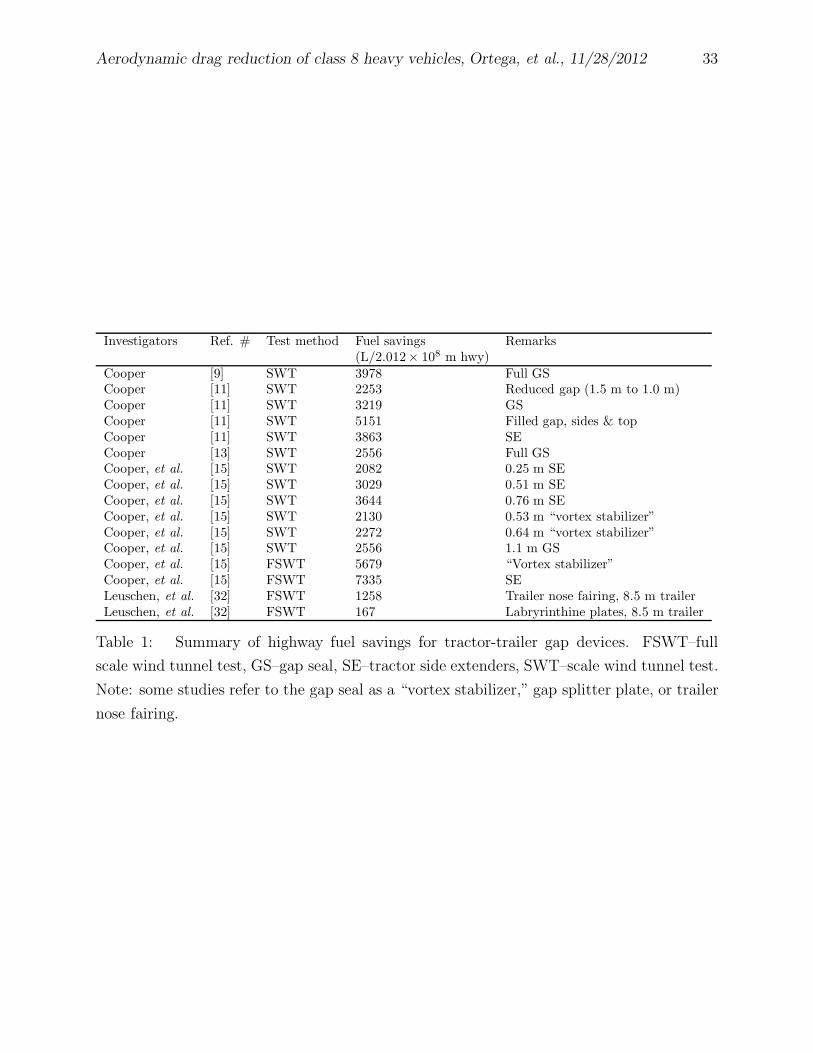
Investigators Ref. # Test method Fuel savings Remarks(L/2.012× 108 m hwy)
Cooper [9] SWT 3978 Full GSCooper [11] SWT 2253 Reduced gap (1.5 m to 1.0 m)Cooper [11] SWT 3219 GSCooper [11] SWT 5151 Filled gap, sides & topCooper [11] SWT 3863 SECooper [13] SWT 2556 Full GSCooper, et al. [15] SWT 2082 0.25 m SECooper, et al. [15] SWT 3029 0.51 m SECooper, et al. [15] SWT 3644 0.76 m SECooper, et al. [15] SWT 2130 0.53 m “vortex stabilizer”Cooper, et al. [15] SWT 2272 0.64 m “vortex stabilizer”Cooper, et al. [15] SWT 2556 1.1 m GSCooper, et al. [15] FSWT 5679 “Vortex stabilizer”Cooper, et al. [15] FSWT 7335 SELeuschen, et al. [32] FSWT 1258 Trailer nose fairing, 8.5 m trailerLeuschen, et al. [32] FSWT 167 Labryrinthine plates, 8.5 m trailer
Table 1: Summary of highway fuel savings for tractor-trailer gap devices. FSWT–full
scale wind tunnel test, GS–gap seal, SE–tractor side extenders, SWT–scale wind tunnel test.
Note: some studies refer to the gap seal as a “vortex stabilizer,” gap splitter plate, or trailer
nose fairing.
Aerodynamic drag reduction of class 8 heavy vehicles, Ortega, et al., 11/28/2012 34
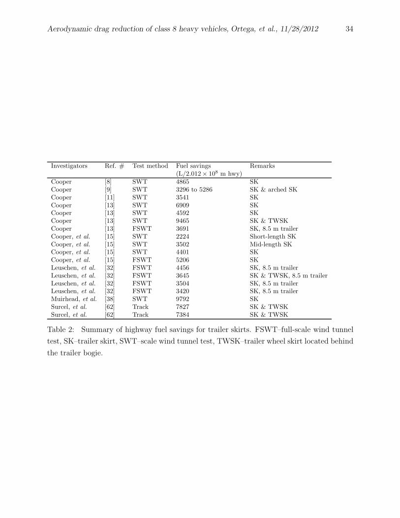
Investigators Ref. # Test method Fuel savings Remarks(L/2.012× 108 m hwy)
Cooper [8] SWT 4865 SKCooper [9] SWT 3296 to 5286 SK & arched SKCooper [11] SWT 3541 SKCooper [13] SWT 6909 SKCooper [13] SWT 4592 SKCooper [13] SWT 9465 SK & TWSKCooper [13] FSWT 3691 SK, 8.5 m trailerCooper, et al. [15] SWT 2224 Short-length SKCooper, et al. [15] SWT 3502 Mid-length SKCooper, et al. [15] SWT 4401 SKCooper, et al. [15] FSWT 5206 SKLeuschen, et al. [32] FSWT 4456 SK, 8.5 m trailerLeuschen, et al. [32] FSWT 3645 SK & TWSK, 8.5 m trailerLeuschen, et al. [32] FSWT 3504 SK, 8.5 m trailerLeuschen, et al. [32] FSWT 3420 SK, 8.5 m trailerMuirhead, et al. [38] SWT 9792 SKSurcel, et al. [62] Track 7827 SK & TWSKSurcel, et al. [62] Track 7384 SK & TWSK
Table 2: Summary of highway fuel savings for trailer skirts. FSWT–full-scale wind tunnel
test, SK–trailer skirt, SWT–scale wind tunnel test, TWSK–trailer wheel skirt located behind
the trailer bogie.
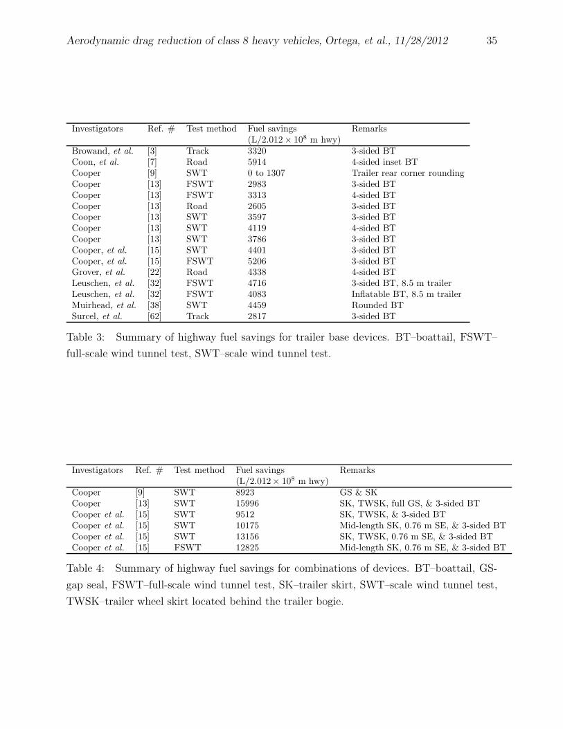
Aerodynamic drag reduction of class 8 heavy vehicles, Ortega, et al., 11/28/2012 35
Investigators Ref. # Test method Fuel savings Remarks(L/2.012× 108 m hwy)
Browand, et al. [3] Track 3320 3-sided BTCoon, et al. [7] Road 5914 4-sided inset BTCooper [9] SWT 0 to 1307 Trailer rear corner roundingCooper [13] FSWT 2983 3-sided BTCooper [13] FSWT 3313 4-sided BTCooper [13] Road 2605 3-sided BTCooper [13] SWT 3597 3-sided BTCooper [13] SWT 4119 4-sided BTCooper [13] SWT 3786 3-sided BTCooper, et al. [15] SWT 4401 3-sided BTCooper, et al. [15] FSWT 5206 3-sided BTGrover, et al. [22] Road 4338 4-sided BTLeuschen, et al. [32] FSWT 4716 3-sided BT, 8.5 m trailerLeuschen, et al. [32] FSWT 4083 Inflatable BT, 8.5 m trailerMuirhead, et al. [38] SWT 4459 Rounded BTSurcel, et al. [62] Track 2817 3-sided BT
Table 3: Summary of highway fuel savings for trailer base devices. BT–boattail, FSWT–
full-scale wind tunnel test, SWT–scale wind tunnel test.
Investigators Ref. # Test method Fuel savings Remarks(L/2.012× 108 m hwy)
Cooper [9] SWT 8923 GS & SKCooper [13] SWT 15996 SK, TWSK, full GS, & 3-sided BTCooper et al. [15] SWT 9512 SK, TWSK, & 3-sided BTCooper et al. [15] SWT 10175 Mid-length SK, 0.76 m SE, & 3-sided BTCooper et al. [15] SWT 13156 SK, TWSK, 0.76 m SE, & 3-sided BTCooper et al. [15] FSWT 12825 Mid-length SK, 0.76 m SE, & 3-sided BT
Table 4: Summary of highway fuel savings for combinations of devices. BT–boattail, GS-
gap seal, FSWT–full-scale wind tunnel test, SK–trailer skirt, SWT–scale wind tunnel test,
TWSK–trailer wheel skirt located behind the trailer bogie.
Aerodynamic drag reduction of class 8 heavy vehicles, Ortega, et al., 11/28/2012 36
Vt
Vwφψ
Vr
Figure 1: Wind vectors relative to the heavy vehicle.
Aerodynamic drag reduction of class 8 heavy vehicles, Ortega, et al., 11/28/2012 37
long sleeper
(LS) tractor
straight-frame
(SF) trailer
trailer
bogielanding
gear (LG)tractor drive
wheels
b)
a)
drop-frame
(DF) trailerday-cab (DC)
tractor
3.7 m
1.1 m
side
extender
x
z
c)
straight-frame
(SF) trailer gap fairing
air bearing
Al platesteel plate
trailerwheelfairing underbody
fairing
2x10⁶
3x10⁶
4x10⁶
5x10⁶
Rew
-0.02
0.00
0.02
0.04
0.06
0.08
d)
CA
wa
vg -
CA
wa
vg(R
ew =
5.2
5x1
06)
turntable
long sleeper (LS)
tractor
Figure 2: a) Long sleeper (LS) tractor and straight-frame (SF) trailer and b) day-cab (DC)
tractor and drop-frame (DF) trailer configurations. c) LS/SF configuration mounted on the
wind tunnel force balance. d) Wind-averaged drag coefficient, CAwavg , relative to CAwavg at
Rew = 5.25 × 10⁶ as a function of Rew.
Aerodynamic drag reduction of class 8 heavy vehicles, Ortega, et al., 11/28/2012 38
Gap fairing 1 (GP1)a)
Gap fairing 2 (GP2)
Gap fairing 3 (GP3)
b)
c)
d) Full side extenders (FULL_SE)
0.4 m
0.5 m
0.4 m
side extenders
Figure 3: a-c) Fairings and d) full side extenders (FULL SE) for the tractor-trailer gap.
Aerodynamic drag reduction of class 8 heavy vehicles, Ortega, et al., 11/28/2012 39
Skirt SK1: Askirt = 8.2 m2
0.95 m
Skirt SK5C_0.2m, SK5C_0.4m: Askirt = 6.9 m2
1.0 m
0.2 m, 0.4 m
Skirt SK2: Askirt = 6.8 m2
0.8 m
Skirt SK5A: Askirt = 5.5 m2
0.9 m
0.4 m
Skirt SK5B: Askirt = 5.9 m2
1.0 m
0.4 m
Skirt SK3: Askirt = 5.0 m2
0.8 m
0.3 m
Skirt SK4: Askirt = 7.4 m2
0.9 m
0.2 m
a)
b)
c)
d)
e)
f)
g)
Figure 4: Trailer side skirts (SK). Askirt denotes the surface area of the trailer skirt.
Aerodynamic drag reduction of class 8 heavy vehicles, Ortega, et al., 11/28/2012 40
Trailer wheel skirt TWSK2: Askirt = 2.8 m2
0.8 m
Trailer wheel skirt TWSK1: Askirt = 1.6 m2
0.8 m
a)
b)
Trailer skirt SK8: Askirt = 3.2 m2e)
0.4 m
Trailer wheel skirt TWSK3: Askirt = 0.9 m2f)
0.4 m
c) Underbody fairing UBF1
0.8 m
Trailer wheel fairing TWF1d)
0.8 m
3.3 m 1.9 m
Figure 5: a-b, e-f) Trailer side skirts (SK) and c-d) underbody devices. Askirt denotes the
surface area of the trailer skirt.
Aerodynamic drag reduction of class 8 heavy vehicles, Ortega, et al., 11/28/2012 41
Boattail BT1
1.2 m
a) θ 12o
Boattail BT2
0.8 m
b) θ 9o
Boattail BT3
0.8 m
c) variable θ
Boattail BT4d) variable θ
0.8 m
~~
~~
Figure 6: Trailer boattails (BT) for the a-c) straight-frame (SF) trailer and the d) drop-
frame (DF) trailer. Boattails a-b) are 4-sided and c-d) are 3-sided.
Aerodynamic drag reduction of class 8 heavy vehicles, Ortega, et al., 11/28/2012 42
-2 0 2 4 6 8 10
0.1
0.2
0.3
0.4
0.5
-2 0 2 4 6 8 10
ψ (deg)
0.2
0.3
0.4
0.5
ψ (deg)
LS/SF
DC/SF
DC/DF
baseline
0.61m_gap + REV_SE
BT2
SK1
0.61m_gap +
REV_SE +
SK1 + BT2
CA -
CA
0
CA -
CA
0
0.00 0.05 0.10 0.15
-Σ ∆
0.00
0.05
0.10
0.15
-∆
UBF1 + TWF1
UBF1 + TWF1 +
BT1
UBF1 + TWF1 +
BT1 + GP1
0.61m_gap + REV_SE
0.61m_ gap +
REV_SE + SK1
0.61m_gap + REV_SE +
SK1 + BT2
CA wavg individual
CA
wa
vg
co
mb
o
a) b)
c)
Figure 7: a) Body-axis drag coefficients as a function of the vehicle yaw angle for the
three baseline configurations (LS–long-sleeper tractor, DC–day-cab tractor, SF–straight-
frame trailer, DF–drop-frame trailer) and b) for the LS/SF configuration with drag re-
duction devices and modifications on the tractor-trailer gap (0.61m gap + REV SE–0.61
m tractor-trailer gap with revised side extenders), underbody (SK1–trailer skirt), and base
(BT2–boattail). Note that the body-axis drag coefficients are relative to an arbitrary value,
CA0. The 0.61m gap + REV SE + SK1 + BT2 data in b) is the drag curve resulting from
the simultaneous installation of the three drag reduction devices and modifications. c) Re-
duction of the wind-averaged drag coefficient for multiple device installations on the LS/SF
configuration. The horizontal axis is the linear summation of the drag reduction values when
the devices are installed individually, while the vertical axis is the drag reduction that results
when the devices are installed simultaneously with one another. The drag reduction values
from multiple devices that combine in a perfectly linear fashion fall upon the 45◦ dashed
line.
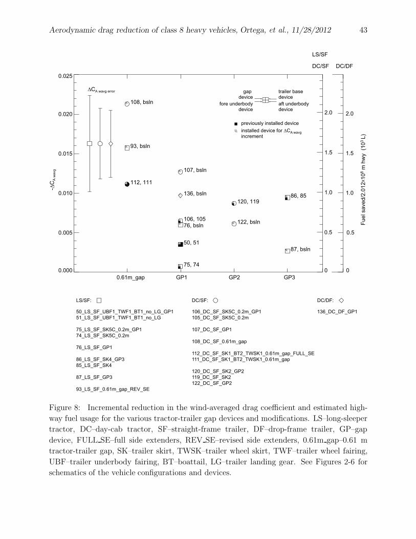
Aerodynamic drag reduction of class 8 heavy vehicles, Ortega, et al., 11/28/2012 43
GP10.61m_gap GP2 GP3
0.000
0.005
0.010
0.015
0.020
0.025
-∆C
A w
avg
106, 105
107, bsln
108, bsln
112, 111
120, 119
122, bsln
50, 51
75, 74
76, bsln
93, bsln
86, 85
87, bsln
136, bsln
LS/SF: DC/SF: DC/DF:
50_LS_SF_UBF1_TWF1_BT1_no_LG_GP1
51_LS_SF_UBF1_TWF1_BT1_no_LG
75_LS_SF_SK5C_0.2m_GP1
74_LS_SF_SK5C_0.2m
76_LS_SF_GP1
86_LS_SF_SK4_GP3
85_LS_SF_SK4
87_LS_SF_GP3
93_LS_SF_0.61m_gap_REV_SE
106_DC_SF_SK5C_0.2m_GP1
105_DC_SF_SK5C_0.2m
107_DC_SF_GP1
108_DC_SF_0.61m_gap
112_DC_SF_SK1_BT2_TWSK1_0.61m_gap_FULL_SE
111_DC_SF_SK1_BT2_TWSK1_0.61m_gap
120_DC_SF_SK2_GP2
119_DC_SF_SK2
122_DC_SF_GP2
136_DC_DF_GP1
DC/SF
LS/SF
DC/DF
Fu
el sa
ve
d/2
.01
2X1
08 m
hw
y (1
03
L)
0
0.5
1.0
1.5
2.0
0
0.5
1.0
1.5
2.0
∆CA wavg error trailer base device
aft underbody device
gap device
fore underbodydevice
previously installed device
installed device for ∆CA wavg
increment
Figure 8: Incremental reduction in the wind-averaged drag coefficient and estimated high-
way fuel usage for the various tractor-trailer gap devices and modifications. LS–long-sleeper
tractor, DC–day-cab tractor, SF–straight-frame trailer, DF–drop-frame trailer, GP–gap
device, FULL SE–full side extenders, REV SE–revised side extenders, 0.61m gap–0.61 m
tractor-trailer gap, SK–trailer skirt, TWSK–trailer wheel skirt, TWF–trailer wheel fairing,
UBF–trailer underbody fairing, BT–boattail, LG–trailer landing gear. See Figures 2-6 for
schematics of the vehicle configurations and devices.
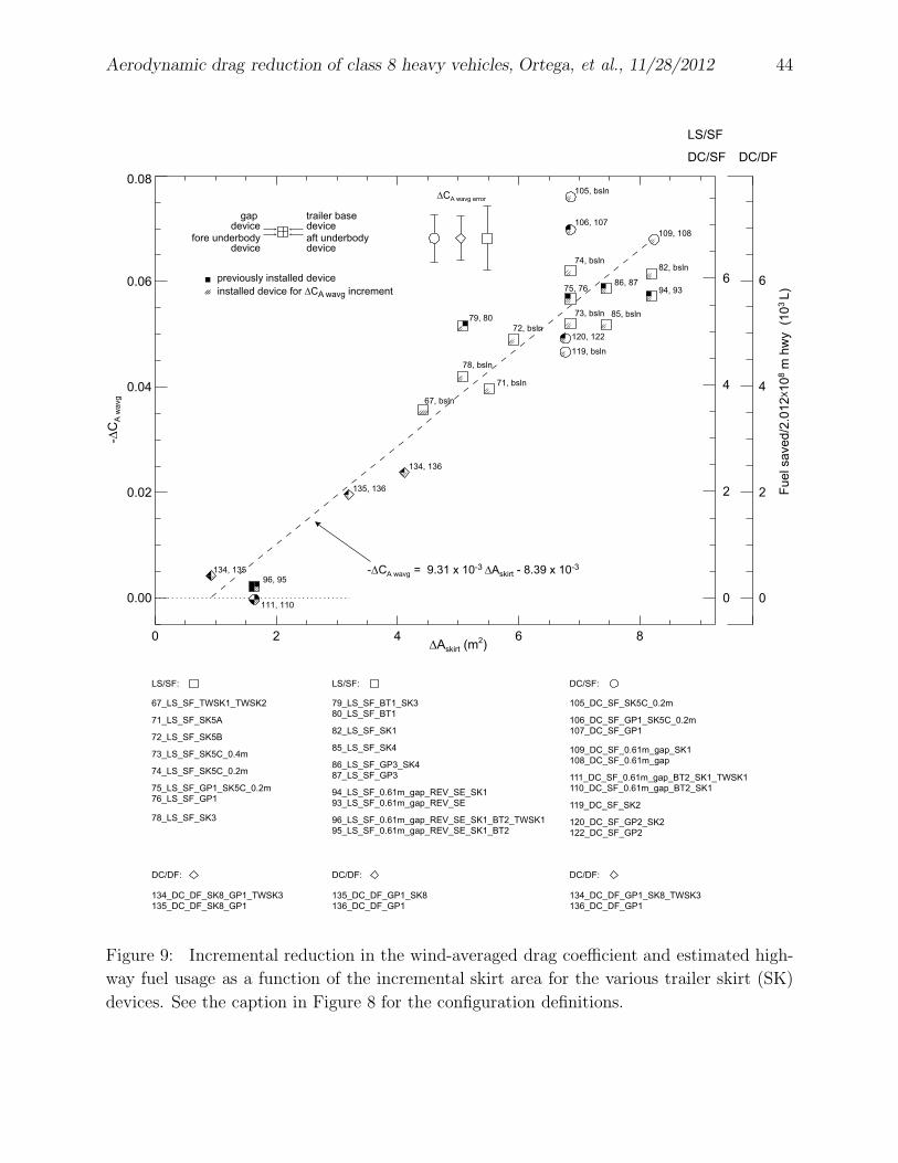
Aerodynamic drag reduction of class 8 heavy vehicles, Ortega, et al., 11/28/2012 44
0 2 4 6 8∆Askirt (m
2)
0.00
0.02
0.04
0.06
0.08
-∆C
A w
avg
105, bsln
106, 107
119, bsln
120, 122
109, 108
111, 110
67, bsln
71, bsln
72, bsln
73, bsln
74, bsln
75, 76
78, bsln
79, 80
82, bsln
85, bsln
86, 8794, 93
96, 95134, 135
135, 136
134, 136
105_DC_SF_SK5C_0.2m
106_DC_SF_GP1_SK5C_0.2m
107_DC_SF_GP1
109_DC_SF_0.61m_gap_SK1
108_DC_SF_0.61m_gap
111_DC_SF_0.61m_gap_BT2_SK1_TWSK1
110_DC_SF_0.61m_gap_BT2_SK1
119_DC_SF_SK2
120_DC_SF_GP2_SK2
122_DC_SF_GP2
134_DC_DF_SK8_GP1_TWSK3
135_DC_DF_SK8_GP1
67_LS_SF_TWSK1_TWSK2
71_LS_SF_SK5A
72_LS_SF_SK5B
73_LS_SF_SK5C_0.4m
74_LS_SF_SK5C_0.2m
75_LS_SF_GP1_SK5C_0.2m
76_LS_SF_GP1
78_LS_SF_SK3
-∆CA wavg = 9.31 x 10⁻³ ∆Askirt - 8.39 x 10⁻³
DC/SF DC/DF
LS/SF
Fu
el sa
ve
d/2
.01
2X1
08 m
hw
y (1
03
L)
0
2
4
6
0
2
4
6
∆CA wavg error
trailer base device
aft underbody device
gap device
fore underbodydevice
previously installed device
installed device for ∆CA wavg increment
LS/SF:
DC/DF:
DC/SF:
79_LS_SF_BT1_SK3
80_LS_SF_BT1
82_LS_SF_SK1
85_LS_SF_SK4
86_LS_SF_GP3_SK4
87_LS_SF_GP3
94_LS_SF_0.61m_gap_REV_SE_SK1
93_LS_SF_0.61m_gap_REV_SE
96_LS_SF_0.61m_gap_REV_SE_SK1_BT2_TWSK1
95_LS_SF_0.61m_gap_REV_SE_SK1_BT2
LS/SF:
135_DC_DF_GP1_SK8
136_DC_DF_GP1
134_DC_DF_GP1_SK8_TWSK3
136_DC_DF_GP1
DC/DF: DC/DF:
Figure 9: Incremental reduction in the wind-averaged drag coefficient and estimated high-
way fuel usage as a function of the incremental skirt area for the various trailer skirt (SK)
devices. See the caption in Figure 8 for the configuration definitions.
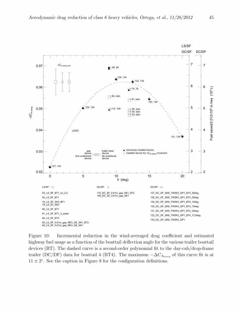
Aerodynamic drag reduction of class 8 heavy vehicles, Ortega, et al., 11/28/2012 45
0 5 10 15 20θ (deg)
0.02
0.03
0.04
0.05
0.06
0.07
-∆C
A w
avg
127, 134
128, 134
129, 134
130, 134
131, 134
132, 134
110, 109
53, bsln
54, bsln
79, 78
80, bsln
81, bsln
84, bsln
95, 94
127_DC_DF_SK8_TWSK3_GP1_BT4_00deg
128_DC_DF_SK8_TWSK3_GP1_BT4_05deg
129_DC_DF_SK8_TWSK3_GP1_BT4_10deg
130_DC_DF_SK8_TWSK3_GP1_BT4_15deg
131_DC_DF_SK8_TWSK3_GP1_BT4_20deg
132_DC_DF_SK8_TWSK3_GP1_BT4_12.5deg
134_DC_DF_SK8_TWSK3_GP1
53_LS_SF_BT1_no_LG
54_LS_SF_BT1
79_LS_SF_SK3_BT1
78_LS_SF_SK3
80_LS_SF_BT1
81_LS_SF_BT1_3_sided
84_LS_SF_BT2
95_LS_SF_0.61m_gap_REV_SE_SK1_BT2
94_LS_SF_0.61m_gap_REV_SE_SK1
110_DC_SF_0.61m_gap_SK1_BT2
109_DC_SF_0.61m_gap_SK1
DC/SF DC/DF
LS/SF
Fu
el sa
ve
d/2
.01
2X1
08 m
hw
y (1
03
L)
2
3
4
5
6
7
2
3
4
5
6
7
LS/SF: DC/SF: DC/DF:
trailer base device
aft underbody device
gap device
fore underbodydevice
previously installed device
installed device for ∆CA wavg increment
∆CA wavg error
LS/SF:
Figure 10: Incremental reduction in the wind-averaged drag coefficient and estimated
highway fuel usage as a function of the boattail deflection angle for the various trailer boattail
devices (BT). The dashed curve is a second-order polynomial fit to the day-cab/drop-frame
trailer (DC/DF) data for boattail 4 (BT4). The maximum −∆CAwavgof this curve fit is at
11 ± 2◦. See the caption in Figure 8 for the configuration definitions.
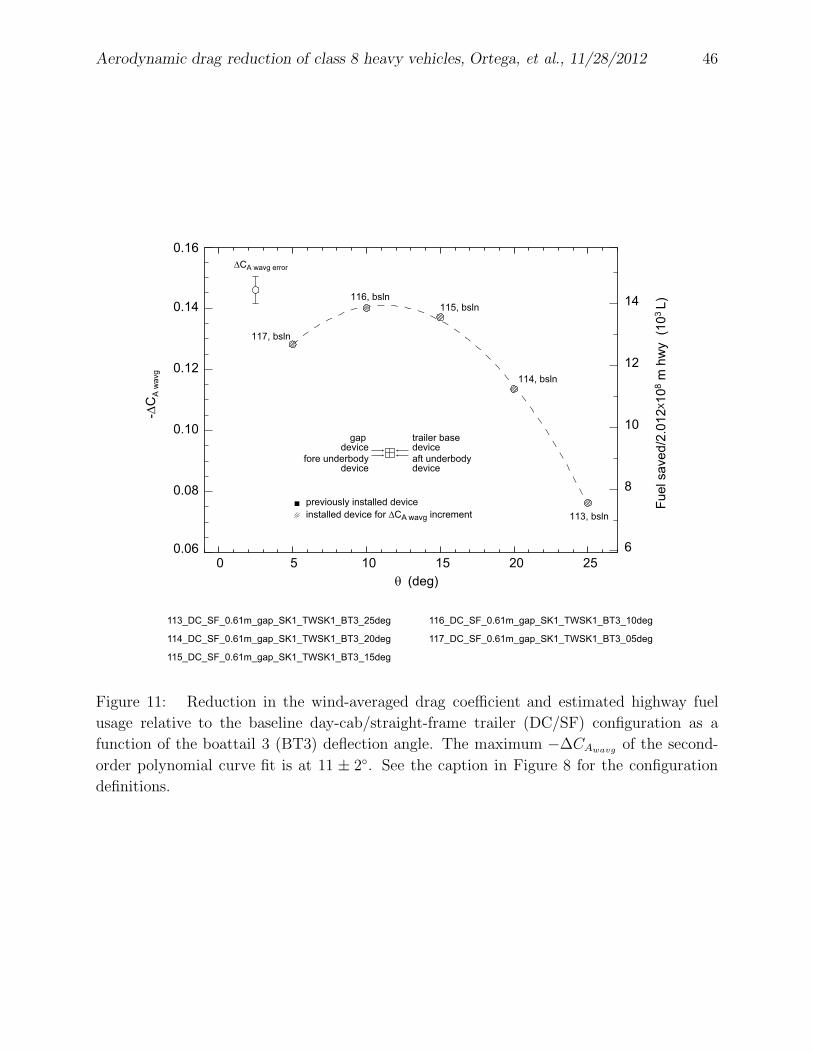
Aerodynamic drag reduction of class 8 heavy vehicles, Ortega, et al., 11/28/2012 46
0 5 10 15 20 25
θ (deg)
0.06
0.08
0.10
0.12
0.14
0.16
113, bsln
114, bsln
115, bsln116, bsln
117, bsln
6
8
10
12
14
113_DC_SF_0.61m_gap_SK1_TWSK1_BT3_25deg
114_DC_SF_0.61m_gap_SK1_TWSK1_BT3_20deg
115_DC_SF_0.61m_gap_SK1_TWSK1_BT3_15degF
ue
l sa
ve
d/2
.01
2X1
08 m
hw
y (1
03
L)
-∆C
A w
avg
trailer base device
aft underbody device
gap device
fore underbodydevice
previously installed device
installed device for ∆CA wavg increment
∆CA wavg error
116_DC_SF_0.61m_gap_SK1_TWSK1_BT3_10deg
117_DC_SF_0.61m_gap_SK1_TWSK1_BT3_05deg
Figure 11: Reduction in the wind-averaged drag coefficient and estimated highway fuel
usage relative to the baseline day-cab/straight-frame trailer (DC/SF) configuration as a
function of the boattail 3 (BT3) deflection angle. The maximum −∆CAwavgof the second-
order polynomial curve fit is at 11 ± 2◦. See the caption in Figure 8 for the configuration
definitions.
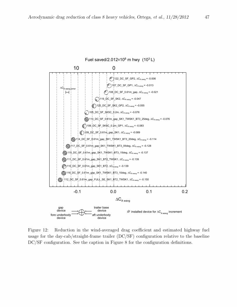
Aerodynamic drag reduction of class 8 heavy vehicles, Ortega, et al., 11/28/2012 47
-0.1 0.0 0.1 0.2
112_DC_SF_0.61m_gap_FULL_SE_SK1_BT2_TWSK1, ∆CA wavg = -0.150
116_DC_SF_0.61m_gap_SK1_TWSK1_BT3_10deg, ∆CA wavg = -0.140
110_DC_SF_0.61m_gap_SK1_BT2, ∆CA wavg = -0.139
111_DC_SF_0.61m_gap_SK1_BT2_TWSK1, ∆CA wavg = -0.139
115_DC_SF_0.61m_gap_SK1_TWSK1_BT3_15deg, ∆CA wavg = -0.137
117_DC_SF_0.61m_gap_SK1_TWSK1_BT3_05deg, ∆CA wavg = -0.128
114_DC_SF_0.61m_gap_SK1_TWSK1_BT3_20deg, ∆CA wavg = -0.114
109_DC_SF_0.61m_gap_SK1, ∆CA wavg = -0.089
106_DC_SF_SK5C_0.2m_GP1, ∆CA wavg = -0.083
113_DC_SF_0.61m_gap_SK1_TWSK1_BT3_25deg, ∆CA wavg = -0.076
105_DC_SF_SK5C_0.2m, ∆CA wavg = -0.076
120_DC_SF_SK2_GP2, ∆CA wavg = -0.055
119_DC_SF_SK2, ∆CA wavg = -0.047
108_DC_SF_0.61m_gap, ∆CA wavg = -0.021
107_DC_SF_GP1, ∆CA wavg = -0.013
122_DC_SF_GP2, ∆CA wavg = -0.006
∆CA wavg
trailer base device
aft underbody device
gap device
fore underbody device
installed device for ∆CA wavg increment
∆CA wavg error
Fuel saved/2.012X108 m hwy (103 L)
10 0
Figure 12: Reduction in the wind-averaged drag coefficient and estimated highway fuel
usage for the day-cab/straight-frame trailer (DC/SF) configuration relative to the baseline
DC/SF configuration. See the caption in Figure 8 for the configuration definitions.
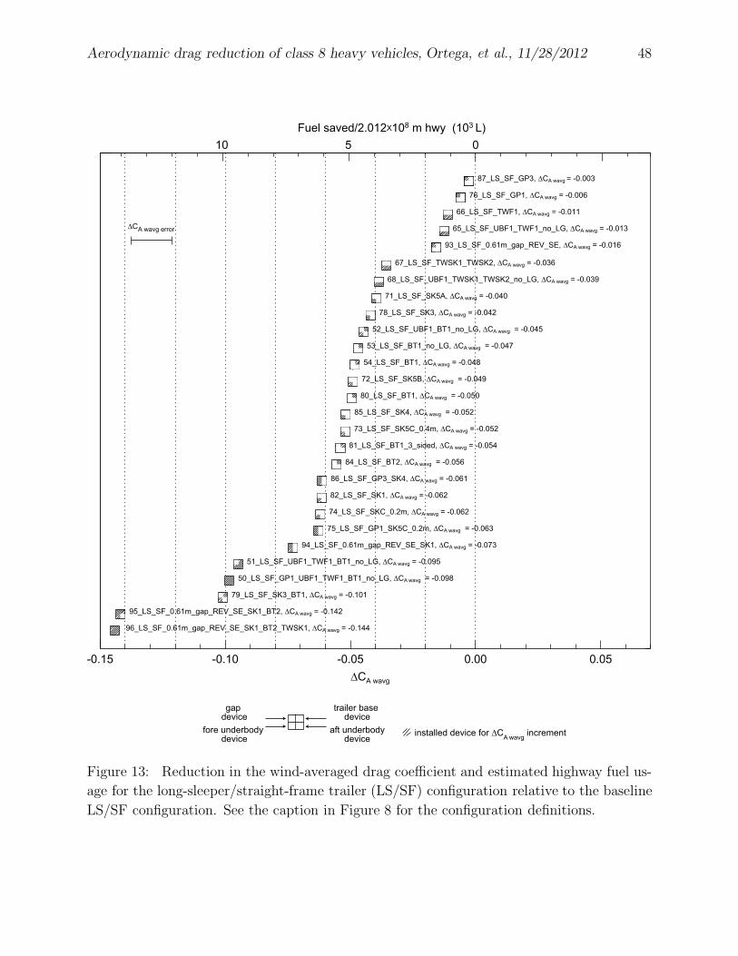
Aerodynamic drag reduction of class 8 heavy vehicles, Ortega, et al., 11/28/2012 48
-0.15 -0.10 -0.05 0.00 0.05
96_LS_SF_0.61m_gap_REV_SE_SK1_BT2_TWSK1, ∆CA wavg = -0.144
95_LS_SF_0.61m_gap_REV_SE_SK1_BT2, ∆CA wavg = -0.142
79_LS_SF_SK3_BT1, ∆CA wavg = -0.101
50_LS_SF_GP1_UBF1_TWF1_BT1_no_LG, ∆CA wavg = -0.098
51_LS_SF_UBF1_TWF1_BT1_no_LG, ∆CA wavg = -0.095
94_LS_SF_0.61m_gap_REV_SE_SK1, ∆CA wavg = -0.073
75_LS_SF_GP1_SK5C_0.2m, ∆CA wavg = -0.063
74_LS_SF_SKC_0.2m, ∆CA wavg = -0.062
82_LS_SF_SK1, ∆CA wavg = -0.062
86_LS_SF_GP3_SK4, ∆CA wavg = -0.061
84_LS_SF_BT2, ∆CA wavg = -0.056
81_LS_SF_BT1_3_sided, ∆CA wavg = -0.054
73_LS_SF_SK5C_0.4m, ∆CA wavg = -0.052
85_LS_SF_SK4, ∆CA wavg = -0.052
80_LS_SF_BT1, ∆CA wavg = -0.050
72_LS_SF_SK5B, ∆CA wavg = -0.049
54_LS_SF_BT1, ∆CA wavg = -0.048
53_LS_SF_BT1_no_LG, ∆CA wavg = -0.047
52_LS_SF_UBF1_BT1_no_LG, ∆CA wavg = -0.045
78_LS_SF_SK3, ∆CA wavg = -0.042
71_LS_SF_SK5A, ∆CA wavg = -0.040
68_LS_SF_UBF1_TWSK1_TWSK2_no_LG, ∆CA wavg = -0.039
67_LS_SF_TWSK1_TWSK2, ∆CA wavg = -0.036
93_LS_SF_0.61m_gap_REV_SE, ∆CA wavg = -0.016
65_LS_SF_UBF1_TWF1_no_LG, ∆CA wavg = -0.013
66_LS_SF_TWF1, ∆CA wavg = -0.011
76_LS_SF_GP1, ∆CA wavg = -0.006
87_LS_SF_GP3, ∆CA wavg = -0.003
∆CA wavg
trailer base device
aft underbodydevice
gap device
fore underbody device
installed device for ∆CA wavg increment
∆CA wavg error
Fuel saved/2.012X108 m hwy (103 L)
10 5 0
Figure 13: Reduction in the wind-averaged drag coefficient and estimated highway fuel us-
age for the long-sleeper/straight-frame trailer (LS/SF) configuration relative to the baseline
LS/SF configuration. See the caption in Figure 8 for the configuration definitions.
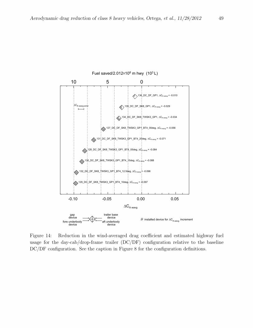
Aerodynamic drag reduction of class 8 heavy vehicles, Ortega, et al., 11/28/2012 49
-0.10 -0.05 0.00 0.05
129_DC_DF_SK8_TWSK3_GP1_BT4_10deg, ∆CA wavg = -0.097
132_DC_DF_SK8_TWSK3_GP1_BT4_12.5deg, ∆CA wavg = -0.096
130_DC_DF_SK8_TWSK3_GP1_BT4_15deg, ∆CA wavg = -0.088
128_DC_DF_SK8_TWSK3_GP1_BT4_05deg, ∆CA wavg = -0.084
131_DC_DF_SK8_TWSK3_GP1_BT4_20deg, ∆CA wavg = -0.071
127_DC_DF_SK8_TWSK3_GP1_BT4_00deg, ∆CA wavg = -0.056
134_DC_DF_SK8_TWSK3_GP1, ∆CA wavg = -0.034
135_DC_DF_SK8_GP1, ∆CA wavg = -0.029
136_DC_DF_GP1, ∆CA wavg = -0.010
∆CA wavg
trailer base device
aft underbody device
gap device
fore underbody device
installed device for ∆CA wavg
increment
Fuel saved/2.012X108 m hwy (103 L)
∆CA wavg error
10 5 0
Figure 14: Reduction in the wind-averaged drag coefficient and estimated highway fuel
usage for the day-cab/drop-frame trailer (DC/DF) configuration relative to the baseline
DC/DF configuration. See the caption in Figure 8 for the configuration definitions.


