Embed Size (px)
Citation preview
Model 7XL
Power Amplifier
Installation/Use and Software Manual
For manual, software and DSP preset updates visit:http://www.nearspeakers.com/xl-amplifier-dsp-files.html
© 2018 Bogen Communications, Inc.All rights reserved.
740-00007C 1802

Every effort was made to ensure that the information in thismanual was complete and accurate at the time of printing,however, all information is subject to change.
WARNING: To Reduce the Risk of Fire or Electric Shock,Do Not Expose this Apparatus to Rain or Moisture.
Always comply with the following basic safety precau-tions when installing and using the unit:
1. Read these instructions.
2. Keep these instructions.
3. Heed all warnings.
4. Follow all instructions.
5. DO NOT use this apparatus near water.
6. Clean only with dry cloth.
7. DO NOT block any ventilation openings. Install in accordance with the manufacturer’s instructions.
8. DO NOT install near any heat sources such as radia-tors, heat registers, stoves, or other apparatus (includ-ing other amplifiers) that produce heat.
9. DO NOT defeat the safety purpose of the polarized orgrounding-type plug. A polarized plug has two bladeswith one wider than the other. A grounding-type plughas two blades and a third grounding prong. The wideblade, or the third prong, are provided for your safety.If the provided plug does not fit into your outlet, consultan electrician for replacement of the obsolete outlet.
10. Protect the power cord from being walked on and/orpinched, particularly at plugs, convenience recepta-cles, and the point where they exit from the apparatus.
11. Only use attachments/accessories which are specifiedby the manufacturer.
12. Unplug this apparatus during lightning storms or whenunused for long periods of time.
13. Refer all servicing to qualified service personnel.Servicing is required when the apparatus has beendamaged in any way, such as power-supply cord orplug is damaged, liquid has been spilled or objectshave fallen into the apparatus, the apparatus has beenexposed to rain or moisture, does not operate normally,or has been dropped.
NOTICE
IMPORTANT SAFETY INSTRUCTIONS
NOTICE FOR DIGITAL EQUIPMENTIn order to obtain full performance of NEAR digitaldevices, always download and install the latest drivers,firmware and/or software versions available online at:http://www.nearspeakers.com
WARNING:The apparatus shall be connected to a mains socketoutlet with a protective earthing connection.
To reduce the risk of fire or electric shock, do not exposethis apparatus to rain or moisture.
The apparatus shall not be exposed to dripping orsplashing and that no objects filled with liquids, such asvases, shall be placed on the apparatus.
Where the mains plug or an appliance coupler is used asthe disconnect device, the disconnect device shallremain readily operable.

Contents
INTRODUCTION ........................................................................................................1
PANEL DESCRIPTIONS ........................................................................................2
7XL Front & Rear Panel Callouts
INSTALLATION ..........................................................................................................3
Ventilation & Mounting Options
CONNECTIONS ........................................................................................................4
Speakers, Inputs, Outputs & Ethernet
OPERATION ................................................................................................................5
Front Controls & Indicators
QUICK-START: USING DSP PRESETS ..........................................................6
QUICK-START: WIRING ..........................................................................................7
SOFTWARE CONTROL......................................................................................8-16
TROUBLESHOOTING ..........................................................................................17
SPECIFICATIONS ..................................................................................................18
LIMITED WARRANTY; EXCLUSION OF CERTAIN DAMAGES ..........19

iii
This Page Left Intentionally Blank

1
Introduction
The NEAR® 7XL Power Amplifier is a highly flexible and intelligent digital audio,2-channel, Class-D power amplifier, delivering up to 700W per channel @4/8/16Ω and 70V/100V Constant Voltage Lines, in Direct Drive, without usinginternal output transformers. A Line Output with independent DSP parametersfor driving additional line-level devices is included.
To guarantee maximum reliability, the two powered output channels include highlyefficient Class-D amplifiers, with independent Switch Mode Power Supplies,including Power Factor Correction, powering each amplifier channel in BridgeTied Load (BTL) mode. The two amplifier output stages are very low noise andlow distortion with efficiency up to 90%, and are also equipped with a full set ofcircuit protections.
Designed to meet the most demanding residential sound system applications,NEAR 7XL’s set of sophisticated controls and parameters for loudspeakers areimplemented using a powerful Digital Signal Processor (DSP) running at48kHz/24bit, and include high-performance 24bit AD/DA Converters. Usercontrolled parameters such as matrix routing, Noise Gate, up to 48dB/Oct IIRHP/LP filters for crossover, parametric EQs (Bell, Notch, Variable Q HI/LOShelving, and HI/LO Pass filters), RMS Compressor, Peak Limiter, polarity, andalignment delay are available. All in all, everything needed to optimize loud-speaker performance is provided by the NEAR 7XL. Moreover, each input/outputchannel provides internal limiting process monitoring to prevent OverflowClipping from occurring in the signal path. Efficient heat dissipation mechanismsand over-temperature protection are implemented, which ensure reliabilitywithout compromise. A useful Pink/White noise generator is included to facilitatesystem setup. All setup parameters for input/output DSP are easily accessibleby using the remote GUI application.

0I OFF
7
2
Panel Descriptions
1. “Stand By” Button - Puts the amplifier into low-power consumption, or “Stand By” mode.The button will appear as back-lit Red when in “Stand By” mode.
2. Signal Clip Indicators - Summed LED read out of corresponding Input and Output.
Green - Signal is present. Red - Clipping condition (detected at various points from input to DSP to amplifier out.
3. LCD Display - Read-out for amplifier state and preset selection.
4. Encoder/Push Button - Used to navigate the LCD screen and presets.
5. Fan Air Intake - Air intake for stepped-speed cooling fan. Fan speed responds as needed to keepthe amplifier cool, while reducing dust build-up. Fan grilles are backed by dust filters. The unitmay be vacuumed for cleaning via front panel.
1. High-Impedance Balanced Inputs - XLR female connectors allow for easy installation andprovide convenient connections to high-impedance balanced inputs. One per input channel.
2. High-Impedance Unbalanced Inputs - RCA type connectors allow for easy installation andprovide convenient connections to high-impedance unbalanced inputs. One per input channel.
3. Line Output - Line-level output. Third DSP output is available as Line Level only, eitherBalanced XLR male, or Unbalanced RCA type.
4. Fan Exhaust - Air outlet for stepped-speed cooling fan.
5. Power Switch - ON/OFF Unit Power.
6. Amplifier Output Speaker Terminals - Pluggable screw terminals connect to speaker loads foreach amplifier channel. Accepts up to #12 AWG wire.
7. Ethernet Connection - Ethernet RJ45 Connector for connection to MS-Windows® equipped comput-er to access additional DSP features via a GUI-based application.
8. IEC Power Input - AC mains connection and fuse.
RearPanel
76 8
1 2 3 4
1 2 3 4 5FrontPanel
5

The 7XL Power Amplifier was designed to either be placed on a table or rack-mounted. For rack-mounted applications, the amplifier(s) can be stacked directly one on top of the other formaximum use of the rack space available without any extra, empty rack spaces between them.An open air space of at least 4" must be provided at the front air intakes and the exhaust toensure adequate cooling. This applies whether rack- or table-mounted. Care should also betaken to ensure that the front intake air is not considerably warmer than the ambient airtemperature. Mount the amplifier low in the rack so that heat dissipation from other equipmentdoes not warm the amplifier's intake air.
1. Rack Mounting: Rack ears are integral with the 7XL amplifier to allow mounting in 19" racks.Load the amplifier into the rack and secure it to the rack (1 & 1A) using 10-32 or M5*16 (orlarger), Truss or Pan head type screws (not included).
2. Table Mounting: Rubber feet, included with the unit, must be secured to the bottom of theamplifier with the screws provided (2 & 2A) to allow it to be situated on a tabletop/shelf.
1
2A1A
2
3
Installation
Ventilation
Amplifier Mounting

4
Connections
For 70/100V and 4/8/16-ohm Speakers
The 7XL was designed to drive 70/100V constant voltage and 4/8/16-ohmtype low-impedance speaker loads. The use of lower impedance speakersmay cause the amplifier to engage its protection circuits and shut downor limit amplifier function.
The Speaker Terminals can accept up to a #12 AWG wire and are plug-gable which make wiring easier. The polarity of each set of speaker out-puts (A & B) is indicated with a “+” and “-” sign. Use these indicators toensure that the polarity of the speakers is correct. Do not ground any ofthe output terminals. Doing so will cause the amplifier to go into protectmode, shutting down operation of the affected channel.
Speakers
Balanced input connections are used when the source device provides abalanced output signal (signal “+”, signal “-”, and ground “G”). This type ofconnection is desirable when operating in electrically noisy environments,where long input cable runs are needed, or to ensure the lowest noiseoperation. If compatible with the source device, this type of connection isrecommended. This input must be selected via the GUI application.
Balanced Input Connections
Unbalanced input connections are used when the source device providesan unbalanced output signal (signal “+” and ground “G”). Since unbal-anced connections do not provide the same amount of noise immunity thata balanced connection does, the connection distances should be made asshort as possible. Unbalanced Input is active by factory default.
Unbalanced Input Connections
Line level output. Third DSP output is available as Line Level only, eitherBalanced XLR male, or Unbalanced RCA type. Both outputs are avail-able at all times.
NOTE: In order for the Line Output Balanced XLR male to be active, besure that the mating connector (XLR female) has a jumper between Pin1and the shell ground tab.
Line Outputs
Ethernet RJ45 Connector for connection to MS-Windows® to accessadditional DSP features via a GUI-based application.
Ethernet

5
Operation
The Power Switch is located on the right rear of the 7XL unit. Press the“I” side of the switch to turn the unit ON. The amplifier will begin itspower-up process once turned on.
Power Switch
The front of the 7XL contains 3 LED indicators, one per output channel:
CLIP – Illuminates Red, it indicates a condition in which the signal isclipping an output stage and automatically reducing signal level toprevent the over load condition.
SIGNAL – Illuminates Green, it indicates that the output is passingsignal normally.
NOTE: By factory default, A and B also monitor Signal/Clip of InA and InB input stages.
Front LED Indicators
This is used to navigate and select through the presets. Push once toaccess security level. Rotate to password “val = 10”. Push again toaccess IP address and preset selection. Rotate again to select desirablepreset. Once desired preset is shown, push again to select preset.Amplifier will now operate with selected preset.
NOTE: A Factory Restore can be accomplished by pushing and holding-inthe Encoder/Push Button while simultaneously pressing the Power SwitchON. This will clear all user settings/presets and restore the unit to itsfactory defaults.
Encoder/Push Button
Puts the amplifier into low-power consumption, or “Stand By”, mode. Thebutton will appear as back-lit Red when in the “Stand By” mode. Pressfor >2 Sec to enter and exit Stand-By Mode.
Stand By Button
0I OFF
Readout for amplifier state and preset selection.
LCD Display NEAR 7XLB - IGS12 IG70V

6
Quick-Start : Using DSP Presets
The NEAR 7XL DSP Amplifier can store up to 16 preset DSP configurations for equalization,crossovers, limiting and other parameters. There are up to 16 configuration presets stored in the7XL’s database that correspond to popular NEAR speaker combinations. NEAR changes thepresets loaded on amplifiers from time-to-time to account for new speaker models. Look for asupplemental presets chart in the product carton to see which presets are loaded on yourspecific unit. If there is no chart go to www.nearspeakers.com/xl-preset-charts.html and useyour unit’s serial number to find the presets stored on your amplifier. You can also find the listof pre-loaded presets by accessing the STORE function in the NEAR DSP graphical userinterface (GUI); see Software Control on page 9 for instructions.
If the speaker combination you are installing does not appear in the provided 7XL presets table,go to: http://www.nearspeakers.com/xl-amplifier-dsp-files/ to see if a preset file exists forthat system. If it does, you can download the file and store it in one of the preset slots by usingthe LOAD function in the GUI (see page 11). New configurations and updates to existing config-urations will be added to the NEAR webpage periodically.
If you create a custom DSP configuration it can be saved in any preset slot, 1 through 16, byover-writing an unneeded factory-loaded configuration. See page 11 for more information.
NEAR 7XL Front Panel
BA
1.) If Stand By Button (A) appears back-lit RED, push and hold for 2-sec to exit.
2.) The Program Button (B) is used to navigate and select through the presets. Pushonce to access security level. Rotate to password “val = 10”. Push again to access IPaddress and preset selection. Rotate again to select the appropriate preset. Once thedesired preset is shown, push again to select that preset. Amplifier will now operate withthe selected preset.

7
Quick-Start : Wiring
Choose your system type, either STEREO 2-CHANNEL or SUMMED MONO
(Channel A: Subwoofers; Channel B: Satellites).Wire the speakers according to your selected system plan.

A MS-Windows® (PC) graphical user interface (GUI) application is available for setting-up the parameters of all the available processes of the NEAR 7XL. This application canbe downloaded from the NEAR website at: www.nearspeakers.com/7xl-amplifier.Look for the link under Resources on the right side of the webpage. This will take youto the XL Series Amplifier GUI and DSP Preset Files page where you can downloadthe USER INTERFACE SOFTWARE.
Once downloaded, find the set-up (.exe) file in your download folder and double click.Follow the prompts to install the NEAR GUI app to your Windows PC.
8
Software Control
Graphical User Interface Control
The GUI operates through an Ethernet connection with the fixed IP address for theamplifier: 192.168.000.100. Take the following steps to set up the Ethernet connectionbetween the amplifier and your PC:
1. Connect your PC to the amplifier's Ethernet port with CAT-5 cable.
2. Make sure the amplifier is "ON". Open the Control Center from your Windows Start menu.
3. Select "Networking and Sharing Center" In the dialog box click on "Change Adaptor Settings".
4. Double click the active Ethernet connection.
5. If your Ethernet port has been previously configured to connect to an office network, click "Details" and copy the network settings to a word processing document so you can reset back to your normal configuration later. If it has not been configured go right to step 6.
6. Scroll down the list until you see "Internet Protocol Version 4 (TCP/IPv4)," double click it or select "Properties".
7. Select "Use the following IP address:" and enter these values:IP address: 192.168.0.5 (If the GUI fails to connect to the amplifier (see page 9), return to this step and change the last digit of the IP address from 5 to some other number, up to the value 10, to correct the IP conflict.)Subnet mask: 255.255.255.0
Default gateway: 192.168.0.1
8. Click "OK"
For an illustrated version of the Ethernet connection procedure go to:www.nearspeakers.com/xl-getting-started.html.For video tutorials go to:: http://www.nearspeakers.com/xl-video-tutorials.html
Connecting the PC to the Amplifier
9
Software Control
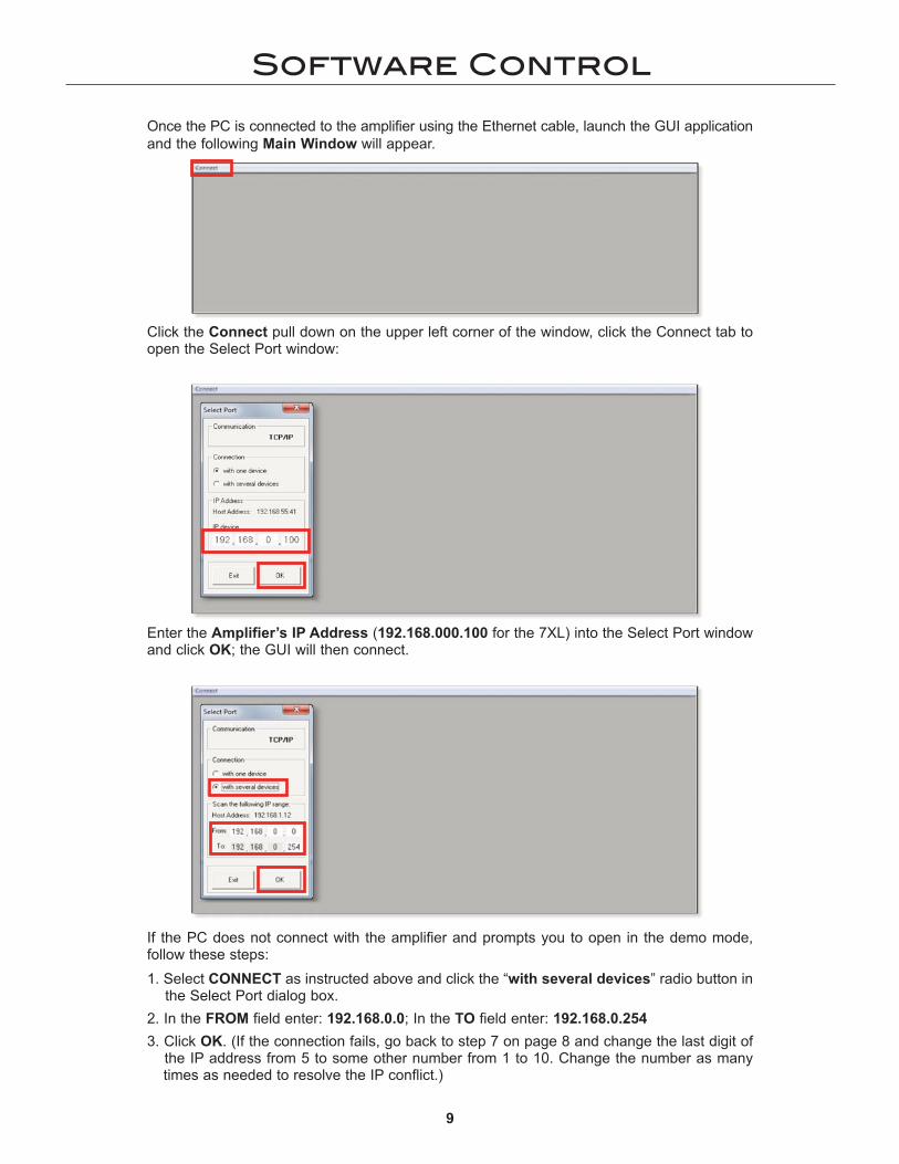
Once the PC is connected to the amplifier using the Ethernet cable, launch the GUI applicationand the following Main Window will appear.
Click the Connect pull down on the upper left corner of the window, click the Connect tab toopen the Select Port window:
Enter the Amplifier’s IP Address (192.168.000.100 for the 7XL) into the Select Port windowand click OK; the GUI will then connect.
If the PC does not connect with the amplifier and prompts you to open in the demo mode,follow these steps:
1. Select CONNECT as instructed above and click the “with several devices” radio button in the Select Port dialog box.
2. In the FROM field enter: 192.168.0.0; In the TO field enter: 192.168.0.254
3. Click OK. (If the connection fails, go back to step 7 on page 8 and change the last digit of the IP address from 5 to some other number from 1 to 10. Change the number as many times as needed to resolve the IP conflict.)

10
Software Control
After the connection takes place, you will see the IP List window appear. Double-click onthe IP Address/Device shown in the IP List.
To Exit Standby Mode, press the red On/Off Button
located in the upper right corner of the window. Thiswill bring you directly to the Home/Level window.
If in Standby Mode, the amplifier will show the following screen:

11
Software Control
Home/Level window.
1. Load: Allows you to load into the GUI a DSP preset file or custom DSP scheme that had been previously stored on your PC.
2. Save: Allows you to store the current DSP scheme or preset to your PC.Note: You can select a folder for saving and assign a name to the preset.
3. Store: Allows you to upload the current preset or custom DSP scheme to the amplifier’s data-base of DSP presets. The preset can be stored in any one of 16 positions and a preset name can be assigned. Once a preset is stored within one of the 16 available locations, it will be accessible via the amplifier front panel and its name will be displayed on the LCD screen.
4. Recall: Opens a window that displays the 16 presets stored in the amplifier. Select any onefrom the list to load it as the current active preset.
5. Copy (IN): Allows you to copy all the parameters of one input channel to the other one.
6. Copy (OUT): Allows you to copy all the parameters of one output channel to another one.
7. Input Link: Gives the user the option to LINK together the 2 input channels. When the2 channels are linked, actions performed on one channel will be reflected on the other.
8. Output Link: Gives the user the option to LINK together any of the output channels. When the channels are linked, actions performed on one channel will be reflected on the other(s).
9. L/D/A/B/1/2/3 Buttons: Clicking on these buttons will allow the opening of the specified DSP processing windows, allowing further feature adjustments.
10. Version: Provides revision level for Software, Firmware, and DSP.
11. Stand By Mode: Puts the amplifier into low-power energy consumption mode. This button mimics the same function as the Front Panel “Stand-By” button.
From the Home/Level window the following Tool Bar actions can be taken:
1 2 3 4 5 6 7 8 9 10 11
12
Software Control
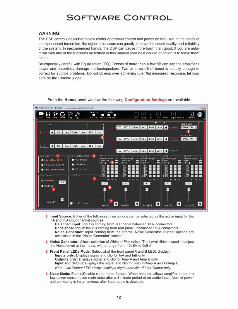
From the Home/Level window the following Configuration Settings are available:
1. Input Source: Either of the following three options can be selected as the active input for theInA and InB input channel sources:
Balanced Input: Input is coming from rear panel balanced XLR connectors.Unbalanced Input: Input is coming from rear panel unbalanced RCA connectors.Noise Generator: Input coming from the internal Noise Generator. Further options areaccessible in the “Noise Generator” section.
2. Noise Generator: Allows selection of White or Pink noise. The Level slider is used to adjust the Noise Level at the inputs, with a range from -40dBV to 0dBV.
3. Front Panel LEDs Mode: Select what the front panel A and B LEDs display:Inputs only: Displays signal and clip for InA and InB only. Outputs only: Displays signal and clip for Amp A and Amp B only.Input and Output: Displays the signal and clip for both In/Amp A and In/Amp B.Note: Line Output LED always displays signal and clip of Line Output only.
4. Sleep Mode: Enable/Disable sleep mode feature. When enabled, allows amplifier to enter a low-power consumption mute state after a 3-minute period of no audio input. Normal power and un-muting is instantaneous after input audio is detected.
1
2
3
4
5
6
7
8
9
WARNING:
The DSP controls described below confer enormous control and power on the user. In the hands ofan experienced technician, the signal processors can greatly improve the sound quality and reliabilityof the system. In inexperienced hands, the DSP can cause more harm than good. If you are unfa-miliar with any of the functions described in this manual your best course of action is to leave themalone.
Be especially careful with Equalization (EQ). Boosts of more than a few dB can sap the amplifier’spower and potentially damage the loudspeakers. Two or three dB of boost is usually enough tocorrect for audible problems. Do not obsess over achieving ruler flat measured response, let yourears be the ultimate judge.

13
Software Control
DELAY Editing Page window.
1. Delay: The delay can be expressed in Time or Distance: Milliseconds [ms] or Meters [m].
2. Delay[ms/m]: Desired Delay to the Input and Output paths can be entered manually, or the delay can be adjusted via arrow buttons (Max Delay per channel is 961ms or 326m):
Adj: the delay can be adjusted by minimum steps of 1 ms or 0.34 metersFine: the delay can be adjusted by minimum steps of 22us or 6.8mm
3. Polarity: this allows the polarity of each input/output to be inverted by 180˚.
1
2 3
2 3
5. VU Meters: VU Meters indicate the Input/Output Levels from -15dBV up to +9dBV at different tap points along the signal stage. Specifically for the Inputs, BG (Before Gain), AG (After Gain), and AC (After Compressor), and for the Outputs, AG (After Gain), BL (Before Limiter), AL (After Limiter).
6. Input/Output Level Sliders: Allows adjustment to the Input/Output Levels, ranging from -60dBV up to +12dBV.
7. Mute Button: Allows Muting of the related Input/Output channels.
8. Speaker Drive Selectors: on the Amplifier Output channels it is possible, independently, todefine the load type the channel has to drive.
16 Ohm/100V – with this selection, the amplifier can drive 16 Ohm Loads or Direct Drive 100V Constant Voltage line.4-8 Ohm/70V - with this selection, the amplifier can drive 4-8 Ohm Loads or Direct Drive70V Constant Voltage line.
9. Block Diagram: Shows the sequence of the Input and Output processes. Clicking on the desired Input/Output process block, will link directly to the page containing the selected process. Clicking on the “loudspeakers icons” on the block diagram Mutes the Input/Output channel.
WARNING:
If you feel the need to reverse polarity to correct for a reversed polarity wiring error, or to check for thebest subwoofer to satellite blending, we strongly recommend reversing polarity on the output stage only,and to avoid reversing polarity on the input stage.

14
Software Control
InA/InB Editing window.
1. Noise Gate: Allows Noise Gate, when necessary, to improve the noise floor of an input source.1A. Thr – Sets threshold where Noise Gate starts to mute input signal; range from -60 to -20 dBV.
Release – Sets the time used by the Noise Gate to unmute the signal once the Threshold is exceeded; rangeis from 10ms up to 1sec.Attack – Sets time used by the Noise Gate to mute the input signal once under the Threshold; its range is from 1ms up to 1sec.
1B. Bypass – Check box used to bypass/disable the Noise Gate feature.
2. EQ Filters: 5 bands of selectable parametric EQ. The following filter types are available:2A. Bell – Peak type filters, with adjustable Center Frequency (20 to 20k Hz), Bandwidth (0.4 to 128 Q), and Gain
(-15 to +15 dBV).Hi/Lo Shelving – Variable Shelving filters with adjustable Center Frequency (20 to 20k Hz), Bandwidth (0.1 to5.1 Q), and Gain (-15 to +15 dBV).Hi/Lo Pass – Variable Hi and Lo Pass filters with adjustable Center Frequency (20 to 20k Hz), and Bandwidth(0.1 to 5.1 Q).Notch – Variable Notch Filters with adjustable Center Frequency (20 to 20k Hz), and Bandwidth (4 to 104 Q).
2B. Byp – Bypass for each particular Filter.2C. Cursor – Pressing Cursor button turns on the drag and drop EQ points on the graphical view.2D. View All - View All opens EQ graphical showing the combined EQ of all Inputs/Outputs.2E. EQ Flat – Pressing the EQ Flat button resets all filter Gains (only) to zero.2F. Bypass - Check box used to bypass all 5 bands EQ Filters.
3. RMS Compressor: An RMS compressor is available on the Inputs. It can be used to reduce the dynamic range of input sources. The following parameters are available:3A. Thr – Threshold where compression starts, ranging from -18dBV up to +12dBV
Ratio – Amount of applied compression, ranging from a 2:1 to 32:1 ratio.Knee – Gain reduction shape around Threshold, ranging from 0 to 100 % (HARD to SOFT).Release – Time to stop compression, once below threshold, ranging from 100ms up to 3 Sec.Attack - Time to start compression, once above threshold, ranging from 5ms up to 200ms.Makeup – Post gain added to compressed signal, ranging from 0 to +12dBV.
3B. Auto Mode – Check box used to activate Auto Mode, which allows RMS compressor to automatically and dyn-amically set the Attack/Release times based on the dynamic characteristics of the musical program.
3C. Auto Knee – Check box activating Auto Knee allowing to set the “Knee” parameter to automatically anddynamically adjust based on the dynamic characteristics of the musical program.
3D. Gain Reduction Meter - Displays the gain reduction due to RMS Compressor.3E. Bypass - Check box used to bypass the RMS Compressor feature.
2A
2D
2E
2F
2B
3B
2C
3A
3C
3E
3D1A
1B

15
Software Control
View All window.
The View All window can be opened pressing the “View All' button. This allows the user to viewall Input and Output response graphics. In addition, the Output response can be shown with andwithout the effects of Routed Input response.
Cursor: The InA/InB Editing window also displays a graphic of the active EQ filters. By turn-ing ON the “Cursor” feature, the Center Frequency and Gain can be adjusted by “dragging”the EQ cursor point with the mouse pointer.
InA/InB Editing window: Cursor (detail).

16
Software Control
Amp A/Amp B/Line Out Editing Page window.
1
4C
4B4A
1. Routing: Matrix Input source selection for specific Output channel. Can be InA, InB, or InA+InB.
2. High and Low Pass Filter: Selection of High Pass and Low Pass crossover Filters on each Output channel.2A. Frequency: The center frequency for all filter types range from 20 – 20kHz.2B. Slope/Type: Available filter Types and Slopes are as follows:
Butterworth - 6, 12, 18, 24, 36, 48 dB/OctLinkwitz Riley - 12, 24, 36, 48 dB/OctBessel - 12, 24 dB/OctBy-Pass - Allows bypass of HP/LP filters.
3. EQ Filters: 7 bands of selectable parametric EQ. The following filter types are available:3A. Bell – Peak type filters, with adjustable Center Frequency (20 to 20kHz), Bandwidth (0.4 to 128 Q),
and Gain (-15 to +15 dBV).Hi/Lo Shelving – Variable Shelving filters with adjustable Center Frequency (20 to 20kHz), Bandwidth (0.1 to 5.1 Q), and Gain (-15 to +15 dBV).Hi/Lo Pass – Variable Hi and Lo Pass filters with adjustable Center Frequency (20 to 20kHz), andBandwidth (0.1 to 5.1 Q).Notch – Variable Notch Filters with adjustable Center Frequency (20 to 20kHz), and Bandwidth(4 to 104 Q).
3B. Byp – Bypass for each particular Filter.3C. Cursor – Pressing the Cursor button turns on the drag and drop EQ points on the graphical view.3D. View All - View All opens the EQ graphical showing the combined EQ of all Inputs/Outputs.3E. EQ Flat – Pressing the EQ Flat button resets all filter Gains (only) to zero.3F. Bypass - Check box allowing to bypass all 7 bands EQ Filters.
4. Peak Limiter: a Peak Limiter is available on the Outputs. It can be used to limit the maximum outputvoltage. The following parameters are available: 4A. Thr – Peak Limiter Threshold, ranging from 6 to 90.4 Vrms for Amp A/B and -18 to 12 dBV for Line Output.
Release – Time to stop limiting, once below threshold, ranging from 100ms up to 5Sec.
Attack – Time to start limiting, once above threshold, ranging from 1ms up to 900ms.4B. Gain Reduction – Displays the gain reduction due to Peak Limiter.4C. Bypass – Check box allowing to bypass the Peak Limiter feature.
2A
2B
2A
2B
3A
3D
3E
3F
3B
3C

Troubleshooting
17
• Power Switch is OFF• REPLACE: AC Mains Fuse opened• Amplifier not plugged in• AC Outlet dead
PROBLEM CONDITION CAUSE
No Front Status LEDor LCD Screen
UNIT OR LCDSCREEN
APPEARS DEAD
• Poor/broken speaker wiring• Defective speakers• DSP routing not set correctly
• Poor electrical connections at Input• Input cable routed near AC cables, power transformer, or other EMI radiating devices• Electrically noisy devices operating on the same AC circuit• Poor equipment grounding
- Ensure that all AC Safety Grounds are connected- Make sure that all components in audio chain are
tied to the same Ground
NO SOUND
NOISE/HUM
DISTORTEDSOUND
INTERMITTENTOPERATION
Signal LED's Off.LCD displays current preset.
• Correct input not selected (XLR or RCA) • No signal from Source • Input not set or wired properly
Signal LED is GREEN. Clip LED is Off.
LCD displays current preset.
Signal LED is GREEN. Limit LED is Off.
• Input signal level too high• Poor speaker connections• Poor signal connections
Signal LED is GREEN. Limit LED is RED (On or
flashing).
• Speaker transformers saturating at low-frequencies, High PassFilter OFF, need additional High-Pass Filtering
• Below Minimum Load Rating on Output• Exceeding Maximum Power Output Rating
Clip LED is RED.
• DC Level at Signal Input• Load impedance too low• Amplifier speaker output is short-circuited• Amplifier too hot (Check for proper ventilation clearances)
Signal LED is GREEN.

Specifications
18
Number of Channels…………………………………......................................….. 2
Dynamic Power (6dB Crest Factor)……………................................... 2 x 700W
Input Sensitivity……………..............................................................................1V
Output Circuitry…………......................................................................... Class D
Output Types…………..................................................... 4/8/16-ohm, 70V, 100V
THD @ Rated power 4 ohms (1kHz)…..................... 0.02% (1W), 0.05% (60W), 0.08% (100W)
S/N Ratio (20K BW) …………...................................... 104dB ref. 70V, full power
Frequency Response…………………….......................... 20Hz – 20kHz , -1.5dB (1W, 4 ohm to 8 ohm load)
Damping Factor………………........................... >120 (4 ohms/1kHz input signal)
Power Supply....……................ 2 x independent Switched-Mode power supplies with PFC (Power Factor Correction)
Operating Range………………….............…......100-240 VAC (50Hz/60Hz), 1.7A
Consumption @ 120VAC…....................................... Idle: 26W/0.33A/87 BTU/hr Standby: 16.6W/0.23A/55 BTU/hr
Full Power: 1637W/14A/809 BTU/hr
Protections………………...…................ Clip, Over-Current, Over/Under Voltage, Output DC and Over-Temperature
Analog Input…................ 2 x XLR electronically balanced, 2 x RCA Unbalanced
Analog Output…........................................ 2 x pluggable terminal amplifier BTL,1 x XLR electronically balanced, 1 x RCA unbalanced
GUI Application…................................. Windows XP® or later, 512MB RAM min.
GENERAL
Dimensions………………………………...................... 19” W x 3.5” H x 15-1/2” D (483mm x 89mm x 394mm) - 2RU
Weight, Net/Shipping………………..........19.7 lbs. (8.65 Kg) / 24.25 lbs. (11 Kg)
ACCESSORIES
AC Power Line Cord………...................................... UK version (P/N: ACLCUK)BS 546 to IEC-320-C13 plug connectors; 1.5m length
………...................................... EU version (P/N: ACLCEU)CEE 7/7 to IEC-320-C13 plug connectors; 1.5m length
(based on full power per channel 700W@8ohms)

Warranty
19
The NEAR® 7XL Power Amplifier is warranted to be free from defects in material and workmanshipfor 3 (three) years from the date of sale to the original purchaser. Any part of any NEAR productcovered by this warranty that, with normal installation and use, becomes defective (as confirmed byBogen upon inspection) during the applicable warranty period, will be repaired or replaced by Bogen,at Bogen’s option, provided the product is shipped insured and prepaid to: Bogen Factory ServiceDepartment, 4570 Shelby Air Drive, Suite 11, Memphis, TN 38118 USA. Repaired or replacementproduct will be returned to you freight prepaid. This warranty does not extend to any of our productsthat have been subjected to abuse, misuse, improper storage, neglect, accident, improper installationor have been modified or repaired or altered in any manner whatsoever, or where the serial number ordate code has been removed or defaced.
THE FOREGOING LIMITED WARRANTY IS BOGEN’S SOLE AND EXCLUSIVE WARRANTY ANDTHE PURCHASER’S SOLE AND EXCLUSIVE REMEDY FOR NEAR PRODUCTS. BOGEN MAKESNO OTHER WARRANTIES OF ANY KIND, EITHER EXPRESS OR IMPLIED, AND ALL IMPLIEDWARRANTIES OF MERCHANTABILITY OR FITNESS FOR A PARTICULAR PURPOSE ARE HERE-BY DISCLAIMED AND EXCLUDED TO THE MAXIMUM EXTENT ALLOWABLE BY LAW. Bogen'sliability arising out of the manufacture, sale or supplying of NEAR products or their use or disposition,whether based upon warranty, contract, tort or otherwise, shall be limited to the price of the product.IN NO EVENT SHALL BOGEN BE LIABLE FOR SPECIAL, INCIDENTAL OR CONSEQUENTIALDAMAGES (INCLUDING, BUT NOT LIMITED TO, LOSS OF PROFITS, LOSS OF DATA OR LOSS OFUSE DAMAGES) ARISING OUT OF THE MANUFACTURE, SALE OR SUPPLYING OF NEAR PROD-UCTS, EVEN IF BOGEN HAS BEEN ADVISED OF THE POSSIBILITY OF SUCH DAMAGES ORLOSSES. Some States do not allow the exclusion or limitation of incidental or consequential damages,so the above limitation or exclusion may not apply to you. This warranty gives you specific legal rights,and you may also have other rights which vary from State to State.
NEAR products that are out of warranty will also be repaired by the Bogen Factory Service Department-- same address as above or call 201-934-8500. The parts and labor involved in these repairs arewarranted for 90 days when repaired by the Bogen Factory Service Department. All shipping chargesin addition to parts and labor charges will be at the owner's expense. All returns require a ReturnAuthorization number. For most efficient warranty or repair service, please include a description ofthe failure.
NEAR Products manufactured and labeled by other companies may be covered by warranties offeredby such companies. Please call Bogen Customer Service or refer to product packaging for manufac-turer’s warranty for non-NEAR branded products.
11/2014
Limited Warranty; Exclusion of Certain Damages
NEAR is a Division of Bogen Communications, Inc.

NEAR is a Division of Bogen Communications, Inc.
Tel.: (855) 350-6327 • E-mail: [email protected]
www.nearspeakers.com


![DMG 2063 Operation Management [Assignment-Gardenia Report]](https://img.pdfslide.us/doc/110x75/544b3383b1af9f88588b4ad6/dmg-2063-operation-management-assignment-gardenia-report.jpg)